EP4052626A1 - Entriegelungsmechanismus - Google Patents
Entriegelungsmechanismus Download PDFInfo
- Publication number
- EP4052626A1 EP4052626A1 EP22163552.7A EP22163552A EP4052626A1 EP 4052626 A1 EP4052626 A1 EP 4052626A1 EP 22163552 A EP22163552 A EP 22163552A EP 4052626 A1 EP4052626 A1 EP 4052626A1
- Authority
- EP
- European Patent Office
- Prior art keywords
- vacuum cleaner
- unlocking
- housing
- holder
- unlocking mechanism
- Prior art date
- Legal status (The legal status is an assumption and is not a legal conclusion. Google has not performed a legal analysis and makes no representation as to the accuracy of the status listed.)
- Granted
Links
Images




Classifications
-
- A—HUMAN NECESSITIES
- A47—FURNITURE; DOMESTIC ARTICLES OR APPLIANCES; COFFEE MILLS; SPICE MILLS; SUCTION CLEANERS IN GENERAL
- A47L—DOMESTIC WASHING OR CLEANING; SUCTION CLEANERS IN GENERAL
- A47L5/00—Structural features of suction cleaners
- A47L5/12—Structural features of suction cleaners with power-driven air-pumps or air-compressors, e.g. driven by motor vehicle engine vacuum
- A47L5/22—Structural features of suction cleaners with power-driven air-pumps or air-compressors, e.g. driven by motor vehicle engine vacuum with rotary fans
-
- A—HUMAN NECESSITIES
- A47—FURNITURE; DOMESTIC ARTICLES OR APPLIANCES; COFFEE MILLS; SPICE MILLS; SUCTION CLEANERS IN GENERAL
- A47L—DOMESTIC WASHING OR CLEANING; SUCTION CLEANERS IN GENERAL
- A47L5/00—Structural features of suction cleaners
- A47L5/12—Structural features of suction cleaners with power-driven air-pumps or air-compressors, e.g. driven by motor vehicle engine vacuum
- A47L5/22—Structural features of suction cleaners with power-driven air-pumps or air-compressors, e.g. driven by motor vehicle engine vacuum with rotary fans
- A47L5/24—Hand-supported suction cleaners
-
- A—HUMAN NECESSITIES
- A47—FURNITURE; DOMESTIC ARTICLES OR APPLIANCES; COFFEE MILLS; SPICE MILLS; SUCTION CLEANERS IN GENERAL
- A47L—DOMESTIC WASHING OR CLEANING; SUCTION CLEANERS IN GENERAL
- A47L5/00—Structural features of suction cleaners
- A47L5/12—Structural features of suction cleaners with power-driven air-pumps or air-compressors, e.g. driven by motor vehicle engine vacuum
- A47L5/22—Structural features of suction cleaners with power-driven air-pumps or air-compressors, e.g. driven by motor vehicle engine vacuum with rotary fans
- A47L5/225—Convertible suction cleaners, i.e. convertible between different types thereof, e.g. from upright suction cleaners to sledge-type suction cleaners
-
- A—HUMAN NECESSITIES
- A47—FURNITURE; DOMESTIC ARTICLES OR APPLIANCES; COFFEE MILLS; SPICE MILLS; SUCTION CLEANERS IN GENERAL
- A47L—DOMESTIC WASHING OR CLEANING; SUCTION CLEANERS IN GENERAL
- A47L9/00—Details or accessories of suction cleaners, e.g. mechanical means for controlling the suction or for effecting pulsating action; Storing devices specially adapted to suction cleaners or parts thereof; Carrying-vehicles specially adapted for suction cleaners
-
- A—HUMAN NECESSITIES
- A47—FURNITURE; DOMESTIC ARTICLES OR APPLIANCES; COFFEE MILLS; SPICE MILLS; SUCTION CLEANERS IN GENERAL
- A47L—DOMESTIC WASHING OR CLEANING; SUCTION CLEANERS IN GENERAL
- A47L9/00—Details or accessories of suction cleaners, e.g. mechanical means for controlling the suction or for effecting pulsating action; Storing devices specially adapted to suction cleaners or parts thereof; Carrying-vehicles specially adapted for suction cleaners
- A47L9/02—Nozzles
- A47L9/06—Nozzles with fixed, e.g. adjustably fixed brushes or the like
-
- A—HUMAN NECESSITIES
- A47—FURNITURE; DOMESTIC ARTICLES OR APPLIANCES; COFFEE MILLS; SPICE MILLS; SUCTION CLEANERS IN GENERAL
- A47L—DOMESTIC WASHING OR CLEANING; SUCTION CLEANERS IN GENERAL
- A47L9/00—Details or accessories of suction cleaners, e.g. mechanical means for controlling the suction or for effecting pulsating action; Storing devices specially adapted to suction cleaners or parts thereof; Carrying-vehicles specially adapted for suction cleaners
- A47L9/24—Hoses or pipes; Hose or pipe couplings
- A47L9/242—Hose or pipe couplings
-
- A—HUMAN NECESSITIES
- A47—FURNITURE; DOMESTIC ARTICLES OR APPLIANCES; COFFEE MILLS; SPICE MILLS; SUCTION CLEANERS IN GENERAL
- A47L—DOMESTIC WASHING OR CLEANING; SUCTION CLEANERS IN GENERAL
- A47L9/00—Details or accessories of suction cleaners, e.g. mechanical means for controlling the suction or for effecting pulsating action; Storing devices specially adapted to suction cleaners or parts thereof; Carrying-vehicles specially adapted for suction cleaners
- A47L9/28—Installation of the electric equipment, e.g. adaptation or attachment to the suction cleaner; Controlling suction cleaners by electric means
- A47L9/2868—Arrangements for power supply of vacuum cleaners or the accessories thereof
- A47L9/2873—Docking units or charging stations
-
- A—HUMAN NECESSITIES
- A47—FURNITURE; DOMESTIC ARTICLES OR APPLIANCES; COFFEE MILLS; SPICE MILLS; SUCTION CLEANERS IN GENERAL
- A47L—DOMESTIC WASHING OR CLEANING; SUCTION CLEANERS IN GENERAL
- A47L9/00—Details or accessories of suction cleaners, e.g. mechanical means for controlling the suction or for effecting pulsating action; Storing devices specially adapted to suction cleaners or parts thereof; Carrying-vehicles specially adapted for suction cleaners
- A47L9/32—Handles
Definitions
- the invention relates to an unlocking mechanism for locking and unlocking the plug connection of a vacuum cleaner, the unlocking mechanism having an unlocking element for unlocking the plug connection between the housing and the suction pipe and/or between the housing and the suction nozzle.
- a suction nozzle designed as a floor nozzle of the vacuum cleaner is continuously pushed back and forth on a floor surface to pick up dust.
- the housing of the vacuum cleaner is connected to a suction tube and a suction nozzle designed as a floor nozzle via plug-in connections. It is possible that the vacuum cleaner housing, suction tube and nozzle can be plugged together in various configurations, e.g. the vacuum cleaner housing directly below the nozzle. However, the vacuum cleaner can also be used in a built-on configuration without a floor nozzle, for example to remove cobwebs. A further construction configuration can provide for using the vacuum cleaner as a hand-held vacuum cleaner, so that the suction tube and floor nozzle are separate from the housing.
- the suction tube and/or the suction nozzle In order to use the structure as a hand-held vacuum cleaner or without a floor nozzle, the suction tube and/or the suction nozzle must be manually disconnected from the housing and turned off.
- the unlocking of the connection between the housing and the suction tube and/or between the housing and the suction nozzle is usually effected via a separately actuated unlocking element of an unlocking mechanism.
- the vacuum cleaner In order to be able to use the vacuum cleaner in a different assembly configuration, the vacuum cleaner must first be removed from the holder and then laboriously converted into the desired assembly configuration and unused components must be stowed away.
- the invention therefore faces the problem of specifying an improved cleaning system and an improved unlocking mechanism.
- the removal of the vacuum cleaner from the holder and the conversion of the vacuum cleaner should be simplified.
- an unlocking mechanism According to the invention, this problem is solved by an unlocking mechanism according to claim 1. Because the holding element holds the vacuum cleaner on the unlocking element in a holding position, the housing being movable from the holding position in at least two removal directions in order to remove the vacuum cleaner from the holder, the unlocking mechanism being designed for this purpose in a first removal direction from the holding element of the holder being unlocked and being locked in a second removal direction, the removal of the vacuum cleaner from the holder and the conversion of the vacuum cleaner into a possible assembly configuration can be simplified.
- the plug-in connection between the housing and the suction tube and/or between the housing and the suction nozzle is unlocked without additional manual actuation of a separate lever or mechanism simply by removing the vacuum cleaner from the holder in two different removal directions. In this way, the vacuum cleaner can be easily removed from the holder either in the overall structure or, for example, as a hand-held vacuum cleaner without an additional handling step.
- the floor surface can be covered by a textile floor covering such as a rug or carpeting or by a hard floor such as e.g. B. a wooden parquet, laminate or PVC flooring can be formed.
- the vacuum cleaner has a blower for generating a negative pressure, through which the floor nozzle guided over a floor surface to be cleaned picks up dust and dirt from the floor surface.
- the suction nozzle designed as a floor nozzle is moved back and forth by the user in the working direction by means of pushing and pulling movements. As a result, the floor nozzle slides over the floor surface to be cleaned.
- the underside of the floor nozzle slides over the carpet, while in the case of smooth floors the underside floats over these floor surfaces at a distance, possibly using spacer bristles.
- the user can, for example, manipulate a vacuum cleaner handle connected to the floor nozzle via a suction pipe.
- the suction mouth of the floor nozzle is elongate and runs essentially transversely to the working direction.
- Elongated in this context means that the preferably substantially rectangular suction mouth has a greater length transverse to the processing direction than width in the processing direction.
- the suction mouth is preferably between 20 and 30 cm long transversely to the processing direction.
- a vacuum cleaner housing of the vacuum cleaner can have a dust collection chamber in which the dust collected via the floor nozzle can be collected in a dust bag, for example.
- the vacuum cleaner with the housing can be removed from the holder in the first removal direction, with the unlocked suction pipe and/or the unlocked suction nozzle remaining in the holder, with the vacuum cleaner with housing and the connected suction tube and/or the connected suction nozzle can be removed together from the holder.
- the vacuum cleaner can thus be very easily removed from the holder either in the second removal direction in the overall structure or as a hand-held vacuum cleaner in the first removal direction without an additional handling step. With the first removal direction, the suction pipe and suction nozzle simply remain in the holder when the housing is removed from the holder.
- An advantageous embodiment of the invention is that the unlocking element unlocks the unlocking mechanism in an unlocking position and locks the unlocking mechanism in a locking position, with the movement of the vacuum cleaner with the housing in the first removal direction moving the unlocking element from the holding element out of the locking position into the unlocking position .
- the plug connection can be unlocked very easily by the retaining element. In this way, the unlocked suction tube or the unlocked suction nozzle remains held in the holder by the holding element, while the vacuum cleaner housing separated with the removal can be used directly as a hand-held vacuum cleaner.
- a preferred embodiment of the invention provides that the unlocking element unlocks the unlocking mechanism in an unlocking position and locks the unlocking mechanism in a locking position, the holding element being designed to move the unlocking element into the unlocking position when the vacuum cleaner is received in the holder, with the Movement of the vacuum cleaner with the housing in the second removal direction, the unlocking element is moved by the holding element from the unlocked position into the locked position or is already in the locked position. With the movement of the vacuum cleaner housing in the second removal direction, the plug connection can be locked or retained by the holding element very easily.
- the locked suction tube or the locked suction nozzle can be used together be removed from the holder with the vacuum cleaner housing, while the vacuum cleaner housing can be removed separately from the unlocked suction pipe and/or from the unlocked suction nozzle in another, in particular the first, removal direction.
- the further development of the invention is particularly advantageous in that the housing of the vacuum cleaner can be moved upwards in the first removal direction for removal from the holding position and the housing of the vacuum cleaner can be moved horizontally in the second removal direction for removal from the holding position.
- the vacuum cleaner body With a simple and intuitive movement of the vacuum cleaner body upwards, the vacuum cleaner can be used as a handheld vacuum cleaner, while the suction tube and suction nozzle remain in the holder. With a horizontal movement forwards, backwards or to the side, the vacuum cleaner with the suction tube and the suction nozzle can be easily removed from the holder as a whole.
- the housing of the vacuum cleaner in the first removal direction can be rotated relative to removal from the holding position and in the second removal direction the housing of the vacuum cleaner can be moved translationally to the holder for removal from the holding position.
- the vacuum cleaner can be used as a handheld vacuum cleaner, while the suction tube and suction nozzle remain in the holder.
- the vacuum cleaner with the suction pipe and the suction nozzle can be easily removed from the holder as a whole.
- An advantageous embodiment of the invention provides that the holder has power contacts which, in the holding position, make contact with resilient charging contacts of the vacuum cleaner for charging a rechargeable battery, the charging contacts being arranged on the unlocking element.
- a rechargeable battery in the vacuum cleaner housing can be easily charged via charging contacts arranged in this way without the removal of the vacuum cleaner being a hindrance due to the electrical contacting between the power contacts of the holder and the charging contacts of the vacuum cleaner.
- the mount is designed as a stand or wall mount.
- the cleaning system can simply be placed on the floor.
- the wall bracket allows the cleaning system to be easily attached to a wall.
- the invention relates to an unlocking mechanism for locking and unlocking a plug connection of a vacuum cleaner between a housing of the vacuum cleaner and a suction tube and/or between the housing and a suction nozzle and/or between the suction tube and the suction nozzle, the unlocking mechanism having an unlocking element for unlocking the plug connection, the unlocking element between an unlocking position in which it unlocks the unlocking mechanism and a locking position in which it locked the unlocking mechanism, is movable, wherein the unlocking mechanism has at least one clamping wedge, which dips into a recess of the unlocking element in the unlocked position, wherein the clamping wedge is supported in the locking position against the unlocking element and locks the connector.
- a cleaning system according to the invention is shown purely schematically in the figures with the reference number 1 .
- the representation according to figure 1 shows a total of three cleaning systems 1, the vacuum cleaner 2 of the cleaning system and the holder 9 of the cleaning system 1 being assembled here in three different variants.
- Variant A is shown on the left, while variant B is in the middle and variant "C" can be seen on the right.
- the vacuum cleaner 2 is held in a holder 9 designed as a wall mount.
- FIG 2 the cleaning system 1 is shown with a vacuum cleaner 2 in a holder 9 designed as a base.
- the cleaning systems 1 for cleaning and maintaining floor surfaces have a vacuum cleaner 2 and a holder 9 for receiving and removing the vacuum cleaner 2 .
- the suction nozzle 5 designed as a floor nozzle is connected here via its connecting piece 15 to a preferably/optionally telescopic suction pipe 4 .
- the telescoping suction pipe 4 is connected to the vacuum cleaner housing 3 via a plug connection 6 .
- This has a handle 16 with which the user can guide the vacuum cleaner 2.
- the vacuum cleaner 2 has a housing 3 and a fan arranged in the housing 3 for generating a negative pressure.
- this negative pressure dirt and grime is picked up from the floor surface to be cleaned by an air flow via the suction mouth of a floor nozzle 5 and transported away via the suction tube 4 into the housing 3 of the vacuum cleaner 2 .
- a separating system which can be designed as a dust bag. The air flow generated by the negative pressure is freed from dirt and grime in the separating system and guided out of the vacuum cleaner 2 via the exhaust air grille. This is connected to the vacuum cleaner housing 3 via the plug-in connection 6 between the housing 3 and the suction pipe 4 .
- the connector 6 includes an unlocking mechanism 7 ( 9 , 10 ) for locking and unlocking the connector 6, the unlocking mechanism 7 ( 9 , 10 ) has an unlocking element 8 for unlocking the plug connection between the housing 3 and the intake manifold 4 .
- a plug connection 6 can also be used to directly connect the suction nozzle 5 to the vacuum cleaner housing 3 .
- On the bracket 9 is a holding element 10 ( figure 5 ) Provided on which the vacuum cleaner 2 when included in the holder 9 in one in the Figures 1 to 3 shown holding position is held. According to the invention, the vacuum cleaner 2 is held on the unlocking element 8 for unlocking the plug connection 6 between the housing 3 and the suction pipe 4 or between the housing 3 and the suction nozzle 5 .
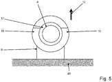
- the vacuum cleaner 2 can be removed in at least two directions 11 ( 4 ), 12 ( figure 5 ) can be removed from the holder 9.
- the unlocking mechanism 7 ( 9 , 10 ) is advantageously designed to move in a first removal direction 11 ( 4 ) of the vacuum cleaner housing 3 to be unlocked from the holder 9 by the holding element 10 of the holder 9 and in a second removal direction 12 ( figure 5 ) of the vacuum cleaner housing 3 to be locked out of the bracket 9.
- the vacuum cleaner 2 can quickly be set up in different configurations be easily removed from the holder 9, as will be explained in more detail below.
- the figure 3 shows a vacuum cleaner 2 of a cleaning system 1 according to the invention in the holding position held by the holder 9 .
- the holding element 10 of the holder 9 surrounds the unlocking element 8 in a geometry 17 provided for this purpose, so that the intake manifold 4 is fixed in the axial direction of the intake manifold, but as shown in FIG figure 5 seen, forward, from the wall 40 ( figure 5 ) gone, can be pulled out.
- This allows the vacuum cleaner housing 3 to be removed in the first removal direction 11 ( 4 ) upwards and the removal of the entire device with vacuum cleaner housing 3 and suction tube 4 and suction nozzle 5 in the second removal direction 12 to the front.
- the vacuum cleaner 2 goes according to figure 3 emerges, wherein the vacuum cleaner housing 3 was removed in the first removal direction 11 from the holding position.
- the unlocked suction tube 4 but also the unlocked suction nozzle 5 remains in the holder 9 in the holding position.
- the unlocking element 8 unlocks the unlocking mechanism 7 ( 9 , 10 ) and locks the unlocking mechanism 7 ( 9 , 10 ).
- the movement of the vacuum cleaner 2 with the housing 3 in the first removal direction 11 has moved the unlocking element 8 from the holding element 10 from the locked position into the unlocked position, so that the vacuum cleaner housing 3 is released.
- the vacuum cleaner housing 3 can be used independently, for example as a hand-held vacuum cleaner.
- the holding element 10 can also hold the unlocking element 8 in the holding position in the unlocking position 8 and only when the vacuum cleaner moves in the second removal direction 12 ( figure 5 ) the unlocking element 8 is moved from the unlocked position to the locked position so that the vacuum cleaner 2 can be safely removed in the overall structure with the suction pipe 4 and the suction nozzle 5 connected.
- figure 4 1 shows that the housing 3 of the vacuum cleaner 2 has been moved upwards in the first removal direction 11 for removal from the holding position.
- the figure 5 shows a plan view from the first removal direction of the holder 9 according to FIG Figures 1 to 4 , In this case the suction pipe 4 has remained in the holding element 10 .
- the holding element 10 is preferably formed in the shape of a fork. This results in a second removal direction 12 via which the vacuum cleaner 2 with the housing 3 and the connected suction pipe 4 and/or the connected suction nozzle 5 can be removed from the holder 9 together.
- the housing 3 of the vacuum cleaner 2 only has to be moved horizontally from the holding position in the second removal direction 12 in order to be released from the fork-shaped holding element 10 of the holder 9 . This can also a slight tilting movement can be performed.
- the housing 3 of the vacuum cleaner 2 can also be removed by rotating the housing 3 relative to the holder in a first removal direction 11 .
- the vacuum cleaner housing 3 can be removed here with the suction pipe 4 together and with the suction nozzle 5 from the holder 9 in a translatory manner.
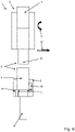
- a plug-in connection 6 with which such a removal of the vacuum cleaner 2 from the holder 9 is possible is shown in figure 6 shown.
- Snap hooks 18 or a bayonet catch, which forms the unlocking mechanism 7, are indicated here.
- the unlocking mechanism 7 can also be formed by a thread.
- a foot release 19 is shown, which in the case of figure 7 forms a tread surface as an additive element on the cap of the connecting piece 15.
- the foot release is shown as a tread with a recess at the back or side of the cap of the connecting piece 15 .
- the figure 9 shows the unlocking mechanism 7 according to the invention in a locked state.
- the unlocking mechanism 7 serves to lock and unlock a plug connection 6 on the vacuum cleaner 2.
- a plug connection 6 between the vacuum cleaner housing 3 and the suction tube 4 is preferably locked.
- the unlocking mechanism 7 has a manually displaceable unlocking element 8.
- This unlocking element 8 can be used to unlock the plug connection 6 in a simple manner.
- the unlocking element 8 can simply be placed between an in figure 9 locking position shown, in which it locks the unlocking mechanism 7, and an in figure 10 unlocking position shown, in which it unlocks the unlocking mechanism 7, are moved.
- the unlocking element 8 can preferably be moved between the locked position and the unlocked position between 3 and 15 mm.
- the clamping wedges of the unlocking mechanism 7 in the unlocked position dip into recesses 14 of the unlocking element 8, while in the locking position the clamping wedges 13 are supported against the unlocking element 8 and as shown in FIG figure 9 to see, lock the connector 6.
- the unlocking element 8 is designed as a cap or collar, which can be simply gripped when the vacuum cleaner components 3, 4, 5 connected to one another via the plug-in connection 6 are pulled apart and then unlocked in the direction of movement.
- the connection 6 between the suction pipe 4 and the suction nozzle 5 could also be achieved while standing by holding the cap 8 or cuff with a foot on a designated area foot release 19 ( figure 7 or 8th ) to be solved.
- clamping wedges 13 which can be brought into two different positions by moving the outer cap 8 on a female connector 20 of the connector 6 and pulling on a male connector 21 of the connector 6, offers a simple possibility To lock connector 6 on a vacuum cleaner 2 or to release.
- the clamping wedges 13 are supported on the female socket 20 of the plug connection 6 and the unlocking element 8 designed as an outer cap and thus prevent the male socket 21 of the plug connection 6 from being pulled out by engaging in the associated recesses.
- the unlocking element 8 designed as an outer cap and thus prevent the male socket 21 of the plug connection 6 from being pulled out by engaging in the associated recesses.
- the clamping wedges 13 can no longer be supported on the outer unlocking element 8.
- the clamping wedges 13 rotate into the recesses 14 provided for this purpose in the unlocking element 8, while the male connector 21 of the plug connection 6 can simply be pulled out, since the clamping wedges 13 no longer dip into the recesses on the male connector 21 of the connector 6 .
- the unlocking mechanism 7 unlocks the connector 6 only when the user grips the unlocking element 8 of the female connector 20 of the connector 6 and moves the two connectors 20, 21 away from each other.
- the plug-in connection 6 advantageously absorbs all the forces that arise.
- the figure 11 is a detailed view of the unlocking mechanism 7 according to FIG figures 9 and 10 .
- the immersion depth should be between 0.5mm and 1.5mm, should be between 5 and 15 degrees.
Landscapes
- Engineering & Computer Science (AREA)
- Mechanical Engineering (AREA)
- Robotics (AREA)
- Nozzles For Electric Vacuum Cleaners (AREA)
- Electric Suction Cleaners (AREA)
Abstract
Description
- Die Erfindung betrifft ein Entriegelungsmechanismus zur Ver- und Entriegelung der Steckverbindung eines Staubsaugers wobei der Entriegelungsmechanismus ein Entriegelungselement zur Entriegelung der Steckverbindung zwischen dem Gehäuse und dem Saugrohr und/oder zwischen dem Gehäuse und der Saugdüse aufweist.
- Im privaten Haushalt sowie im Gewerbe kommen Reinigungssysteme mit Staubsaugern zur Reinigung von Flächen wie textilen Bodenbelägen und glatten Böden zum Einsatz. Dabei wird zur Staubaufnahme eine als Bodendüse ausgebildete Saugdüse des Staubsaugers auf einer Bodenfläche kontinuierlich vor- und zurückgeschoben.
- Aus dem Stand der Technik bekannt sind insbesondere Reinigungssysteme mit Akku-Sticksaugern, die in der Regel in verschiedenen Aufbaukonfigurationen verwendet werden können. Bei einem Gesamtaufbau ist das Gehäuse des Staubsaugers mit einem Saugrohr und einer als Bodendüse ausgebildeten Saugdüse über Steckverbindungen verbunden. Dabei ist es möglich, dass Staubsaugergehäuse, Saugrohr und Düse in verschiedenen Konfigurationen zusammensteckbar sind, z.B. das Staubsaugergehäuse direkt unten an der Düse. Der Staubsauger kann aber in einer Aufbaukonfiguration auch ohne Bodendüse beispielsweise zur Entfernung von Spinnenweben genutzt werden. Eine weitere Aufbaukonfiguration kann vorsehen, den Staubsauger als Handstaubsauger zu verwenden, sodass Saugrohr und Bodendüse von dem Gehäuse getrennt sind. Um den Aufbau als Handstaubsauger oder ohne Bodendüse zu nutzen, müssen das Saugrohr und/oder die Saugdüse vom Gehäuse manuell getrennt und abgestellt werden. Die Entriegelung der Verbindung zwischen dem Gehäuse und dem Saugrohr und/oder zwischen dem Gehäuse und der Saugdüse erfolgt in der Regel über ein separat zu betätigendes Entriegelungselement eines Entriegelungsmechanismus. Weiterhin ist bekannt den Staubsauger eines solchen Reinigungssystems in einer Halterung aufzunehmen, um den Staubsauger bei Nichtbenutzung in einer der Aufbaukonfigurationen zu parken. Um den Staubsauger im Anschluss in einer anderen Aufbaukonfiguration nutzen zu können, muss der Staubsauger zunächst aus der Halterung entnommen werden und im Anschluss mühsam in die gewünschte Aufbaukonfiguration umgebaut werden und nicht genutzte Komponenten müssen verstaut werden.
- Der Erfindung stellt sich somit das Problem, ein verbessertes Reinigungssystem und einen verbesserten Entriegelungsmechanismus anzugeben. Insbesondere soll ein die Entnahme des Staubsaugers aus der Halterung und der Umbau des Staubsaugers vereinfacht werden.
- Erfindungsgemäß wird dieses Problem durch einen Entriegelungsmechanismus nach Anspruch 1 gelöst. Dadurch, dass das Halteelement den Staubsauger an dem Entriegelungselement in einer Halteposition hält, wobei zur Entnahme des Staubsaugers aus der Halterung das Gehäuse aus der Halteposition in mindestens zwei Entnahmerichtungen bewegbar ist, wobei der Entriegelungsmechanismus dazu ausgebildet ist in einer ersten Entnahmerichtung von dem Halteelement der Halterung entriegelt zu sein und in einer zweiten Entnahmerichtung verriegelt zu sein, kann die Entnahme des Staubsaugers aus der Halterung und der Umbau des Staubsaugers in eine mögliche Aufbaukonfiguration vereinfacht werden. Die Entriegelung der Steckverbindung zwischen dem Gehäuse und dem Saugrohr und/oder zwischen dem Gehäuse und der Saugdüse erfolgt ohne zusätzliche manuelle Betätigung eines separaten Hebels oder Mechanismus einfach durch Entnahme des Staubsaugers aus der Halterung in zwei unterschiedlichen Entnahmerichtungen. So kann der Staubsauger einfach aus der Halterung entweder im Gesamtaufbau oder beispielsweise als Handstaubsauger ohne einen zusätzlichen Handhabungsschritt entnommen werden.
- Die Bodenfläche kann durch einen textilen Bodenbelag wie einen Teppich oder Teppichboden oder durch einen Hartboden wie z. B. ein Holzparkett, Laminat oder einen PVC-Bodenbelag gebildet werden.
- Der Staubsauger weist ein Gebläse zur Erzeugung eines Unterdruckes auf, durch den die über eine zu reinigende Bodenfläche geführte Bodendüse Staub und Schmutz von der Bodenfläche aufnimmt. Hierzu wird die als Bodendüse ausgebildete Saugdüse durch den Benutzer mittels Schub- und Zugbewegungen in Bearbeitungsrichtung vor und zurück bewegt. Hierdurch gleitet die Bodendüse über die zu reinigende Bodenfläche. Insbesondere bei langflorigen Teppichen gleitet die Unterseite der Bodendüse über den Teppich, während die Unterseite bei Glattböden beabstandet, gegebenenfalls durch Abstandsborsten, über diese Bodenflächen hinweg schwebt. Der Benutzer kann dazu beispielsweise einen über ein Saugrohr mit der Bodendüse verbundenen Griff des Staubsaugers handhaben. Damit die Reinigung und Pflege des Bodenbelags möglichst effektiv ausgeführt werden kann, ist der Saugmund der Bodendüse länglich ausgebildet und verläuft im Wesentlichen quer zur Bearbeitungsrichtung. Länglich ausgebildet bedeutet in diesem Zusammenhang, dass der vorzugsweise im Wesentlichen rechteckige Saugmund eine größere Länge quer zur Bearbeitungsrichtung aufweist, als Breite in Bearbeitungsrichtung. Der Saugmund ist vorzugsweise zwischen 20 und 30 cm quer zur Bearbeitungsrichtung lang. Ein Staubsaugergehäuse des Staubsaugers kann eine Staubaufnahmekammer aufweisen, in welcher der über die Bodendüse aufgenommene Staub beispielsweise in einem Staubbeutel gesammelt werden kann.
- Vorteilhafte Ausgestaltungen und Weiterbildungen der Erfindung ergeben sich aus den abhängigen Ansprüchen. Es ist darauf hinzuweisen, dass die in den Ansprüchen einzeln aufgeführten Merkmale auch in beliebiger und technologisch sinnvoller Weise miteinander kombiniert werden können und somit weitere Ausgestaltungen der Erfindung aufzeigen.
- Gemäß einer vorteilhaften Ausgestaltung der Erfindung ist vorgesehen, dass in der ersten Entnahmerichtung der Staubsauger mit dem Gehäuse aus der Halterung entnehmbar ist, wobei das entriegelte Saugrohr und/oder die entriegelte Saugdüse in der Halterung verbleiben, wobei in der zweiten Entnahmerichtung der Staubsauger mit Gehäuse und dem verbundenen Saugrohr und/oder der verbundenen Saugdüse aus der Halterung zusammen entnehmbar ist. Der Staubsauger kann so aus der Halterung sehr einfach entweder in der zweiten Entnahmerichtung im Gesamtaufbau oder als Handstaubsauger in der ersten Entnahmerichtung ohne einen zusätzlichen Handhabungsschritt entnommen werden. Bei der ersten Entnahmerichtung verbleiben Saugrohr und Saugdüse bei Entnahme des Gehäuses aus der Halterung einfach in der Halterung zurück.
- Eine vorteilhafte Ausführung der Erfindung ist, dass das Entriegelungselement in einer Entriegelungsstellung den Entriegelungsmechanismus entriegelt und in einer Verriegelungsstellung den Entriegelungsmechanismus verriegelt, wobei durch die Bewegung des Staubsaugers mit dem Gehäuse in der ersten Entnahmerichtung das Entriegelungselement von dem Halteelement aus der Verriegelungsstellung in die Entriegelungsstellung bewegt wird. Mit der Bewegung des Staubsaugergehäuses in der ersten Entnahmerichtung kann so sehr einfach eine Entriegelung der Steckverbindung durch das Halteelement erfolgen. Auf diese Weise verbleibt das entriegelte Saugrohr oder die entriegelte Saugdüse in der Halterung von dem Halteelement gehalten, während das mit der Entnahme abgetrennte Staubsaugergehäuse als Handstaubsauger unmittelbar verwendet werden kann.
- Eine bevorzugte Ausführung der Erfindung sieht vor, dass das Entriegelungselement in einer Entriegelungsstellung den Entriegelungsmechanismus entriegelt und in einer Verriegelungsstellung den Entriegelungsmechanismus verriegelt, wobei das Halteelement dazu ausgebildet ist, das Entriegelungselement bei Aufnahme des Staubsaugers in der Halterung in die Entriegelungsstellung zu bewegen, wobei durch die Bewegung des Staubsaugers mit dem Gehäuse in der zweiten Entnahmerichtung das Entriegelungselement von dem Halteelement aus der Entriegelungsstellung in die Verriegelungsstellung bewegt wird oder sich bereits in der Verriegelungsstellung befindet. Mit der Bewegung des Staubsaugergehäuses in der zweiten Entnahmerichtung kann so sehr einfach eine Verriegelung der Steckverbindung durch das Halteelement erfolgen bzw. erhalten bleiben. Auf diese Weise kann das verriegelte Saugrohr oder die verriegelte Saugdüse gemeinsam mit dem Staubsaugergehäuse aus der Halterung genommen werden, während das Staubsaugehäuse in einer anderen, insbesondere der ersten, Entnahmerichtung separat von dem entriegelten Saugrohr und/oder von der entriegelten Saugdüse entnommen werden kann.
- Besonders vorteilhaft ist die Weiterbildung der Erfindung, dass in der ersten Entnahmerichtung das Gehäuse des Staubsaugers zur Entnahme aus der Halteposition nach oben bewegbar ist und in der zweiten Entnahmerichtung das Gehäuse des Staubsaugers zur Entnahme aus der Halteposition horizontal bewegbar ist. Mit einer einfachen und intuitiven Bewegung des Staubsaugergehäuses nach oben kann so der Staubsauger als Handstaubsauger verwendet werden, während das Saugrohr und die Saugdüse in der Halterung verbleiben. Bei einer horizontalen Bewegung nach vorne, hinten oder zur Seite kann der Staubsauger mit dem Saugrohr und der Saugdüse einfach im Gesamtaufbau aus der Halterung entnommen werden.
- Weiter vorteilhaft ist die Ausgestaltung der Erfindung, dass in der ersten Entnahmerichtung das Gehäuse des Staubsaugers zur Entnahme aus der Halteposition relativ drehbar ist und in der zweiten Entnahmerichtung das Gehäuse des Staubsaugers zur Entnahme aus der Halteposition translatorisch zur Halterung bewegbar ist. Mit einer einfachen und intuitiven Drehbewegung des Staubsaugergehäuses kann so der Staubsauger als Handstaubsauger verwendet werden, während das Saugrohr und die Saugdüse in der Halterung verbleiben. Bei einer translatorischen Bewegung nach oben, unten, vorne, hinten oder zur Seite kann der Staubsauger mit dem Saugrohr und der Saugdüse einfach im Gesamtaufbau aus der Halterung entnommen werden.
- Eine vorteilhafte Ausführungsform der Erfindung sieht vor, dass die Halterung über Stromkontakte verfügt, die in der Halteposition federnde Ladekontakte des Staubsaugers zur Aufladung eines Akkumulators kontaktieren, wobei die Ladekontakte am Entriegelungselement angeordnet sind. Über so angeordnete Ladekontakte kann ein Akkumulator im Staubsaugergehäuse einfach aufgeladen werden, ohne dass die Entnahme des Staubsaugers durch die elektrische Kontaktierung zwischen den Stromkontakten der Halterung und den Ladekontakten des Staubsaugers hinderlich ist.
- Gemäß einer vorteilhaften Ausgestaltung der Erfindung ist vorgesehen, dass die Halterung als Standfuß oder Wandhalterung ausgebildet ist. Mit einer Halterung als Standfuß kann das Reinigungssystem einfach auf dem Boden abgestellt werden. Die Wandhalterung ermöglicht eine einfache Befestigung des Reinigungssystems an einer Wand.
- Gegenstand der Erfindung ist ein Entriegelungsmechanismus zur Ver- und Entriegelung einer Steckverbindung eines Staubsaugers zwischen einem Gehäuse des Staubsaugers und einem Saugrohr und/oder zwischen dem Gehäuse und einer Saugdüse und/oder zwischen dem Saugrohr und der Saugdüse, wobei der Entriegelungsmechanismus ein Entriegelungselement zur Entriegelung der Steckverbindung aufweist, wobei das Entriegelungselement zwischen einer Entriegelungsstellung in der es den Entriegelungsmechanismus entriegelt und einer Verriegelungsstellung in der es den Entriegelungsmechanismus verriegelt, bewegbar ist, wobei der Entriegelungsmechanismus mindestens einen Klemmkeil aufweist, der in der Entriegelungsstellung in eine Aussparung des Entriegelungselements eintaucht, wobei sich der Klemmkeil in der Verriegelungsstellung gegen das Entriegelungselement abstützt und die Steckverbindung verriegelt. Mit einem solchen Entriegelungsmechanismus ist eine einfache Ver- und Entriegelung einer Steckverbindung eines Staubsaugers möglich, da mit dem Entriegelungselement eine intuitive Bewegung zur Entriegelung genutzt werden kann. Hierdurch lässt sich die Steckverbindung durch einen einfachen Griff und eine Zugbewegung entriegeln und die über die Steckverbindung verbundenen Teile sich lösen.
- Weitere Merkmale, Einzelheiten und Vorteile der Erfindung ergeben sich aufgrund der nachfolgenden Beschreibung sowie anhand der Zeichnungen. Ausführungsbeispiele der Erfindung sind in den folgenden Zeichnungen rein schematisch dargestellt und werden nachfolgend näher beschrieben. Einander entsprechende Gegenstände oder Elemente sind in allen Figuren mit den gleichen Bezugszeichen versehen. Es zeigt
- Figur 1
- Reinigungssystem,
- Figur 2
- Reinigungssystem mit Standfuß,
- Figur 3
- Detailansicht mit Staubsauger in Halteposition,
- Figur 4
- Detailansicht mit entnommenem Staubsaugergehäuse,
- Figur 5
- Draufsicht auf Halterung mit Saugrohr,
- Figur 6
- Detailansicht mit entnommenem Staubsaugergehäuse,
- Figur 7 u. 8
- Fußentriegelung,
- Figur 9
- Entriegelungsmechanismus verriegelt,
- Figur 10
- Entriegelungsmechanismus entriegelt und
- Figur 11
- Detailansicht zu Entriegelungsmechanismus.
- In den Figuren mit dem Bezugszeichen 1 bezeichnet ist ein erfindungsgemäßes Reinigungssystem rein schematisch dargestellt. Die Darstellung gemäß
Figur 1 zeigt insgesamt drei Reinigungssysteme 1, wobei hier der Staubsauger 2 des Reinigungssystems und die Halterung 9 des Reinigungssystems 1 in drei unterschiedlichen Varianten zusammengesetzt sind. Links ist die Variante A zu sehen, während in der Mitte die Variante B und rechts die Variante "C zu sehen sind. In allen drei Varianten ist der Staubsauger 2 in einer als Wandhalterung ausgebildeten Halterung 9 gehalten. - In
Figur 2 ist das Reinigungssystem 1 mit einem Staubsauger 2 in einer als Standfuß ausgebildeten Halterung 9 gezeigt. - Alle diese Varianten gemäß
Figur 1 und2 haben gemeinsam, dass die Reinigungssysteme 1 zur Reinigung und Pflege von Bodenflächen einen Staubsauger 2 und eine Halterung 9 zur Auf- und Entnahme des Staubsaugers 2 aufweisen. Die als Bodendüse ausgebildete Saugdüse 5 ist hier über ihren Anschlussstutzen 15 mit einem vorzugsweise/optional teleskopierbar ausgestalteten Saugrohr 4 verbunden. Das teleskopierbare Saugrohr 4 ist über eine Steckverbindung 6 mit dem Staubsaugergehäuse 3 verbunden. Dieses hat einen Handgriff 16, mit dem der Benutzer den Staubsauger 2 führen kann. Der Staubsauger 2 verfügt über ein Gehäuse 3 und ein in dem Gehäuse 3 angeordnetes Gebläse zur Erzeugung eines Unterdruckes. Mittels dieses Unterdruckes wird Schmutz und Dreck von der zu reinigenden Bodenfläche durch einen Luftstrom über den Saugmund einer Bodendüse 5 aufgenommen und über das Saugrohr 4 in das Gehäuse 3 des Staubsaugers 2 abtransportiert. In diesem Gehäuse 3 vorgesehen ist ein Abscheidesystem, welches als Staubbeutel ausgebildet sein kann. Der durch den Unterdruck erzeugte Luftstrom wird in dem Abscheidesystem von Schmutz und Dreck befreit und über Abluftgitter aus dem Staubsauger 2 herausgeleitet. Über die Steckverbindung 6 zwischen dem Gehäuse 3 und dem Saugrohr 4 ist dieses mit dem Staubsaugergehäuse 3 verbunden. Die Steckverbindung 6 umfasst einen Entriegelungsmechanismus 7 (Fig. 9 ,10 ) zur Ver- und Entriegelung der Steckverbindung 6, wobei der Entriegelungsmechanismus 7 (Fig. 9 ,10 ) ein Entriegelungselement 8 zur Entriegelung der Steckverbindung zwischen dem Gehäuse 3 und dem Saugrohr 4 aufweist. Eine solche Steckverbindung 6 kann auch zur direkten Verbindung der Saugdüse 5 mit dem Staubsaugergehäuse 3 genutzt werden. An der Halterung 9 ist ein Halteelement 10 (Fig. 5 ) vorgesehen, am dem der Staubsauger 2 bei Aufnahme in der Halterung 9 in einer in denFiguren 1 bis 3 gezeigten Halteposition gehalten wird. Hierbei ist der Staubsauger 2 erfindungsgemäß an dem Entriegelungselement 8 zur Entriegelung der Steckverbindung 6 zwischen dem Gehäuse 3 und dem Saugrohr 4 oder zwischen dem Gehäuse 3 und der Saugdüse 5 gehalten. Aus der hierdurch festgelegten Haltposition kann der Staubsauger 2 in mindestens zwei Entnahmerichtungen 11 (Fig. 4 ), 12 (Fig. 5 ) aus der Halterung 9 entnommen werden. Der Entriegelungsmechanismus 7 (Fig. 9 ,10 ) ist vorteilhaferweise dazu ausgebildet ist in einer ersten Entnahmerichtung 11 (Fig. 4 ) des Staubsaugergehäuses 3 aus der Halterung 9 von dem Halteelement 10 der Halterung 9 entriegelt zu sein und in einer zweiten Entnahmerichtung 12 (Fig. 5 ) des Staubsaugergehäuses 3 aus der Halterung 9 verriegelt zu sein. Hierdurch kann der Staubsauger 2 schnell in unterschiedlichen Aufbaukonfigurationen einfach aus der Halterung 9 entnommen werden, wie im Folgenden noch genauer erläutert wird. - Die
Figur 3 zeigt einen Staubsauger 2 eines erfindungsgemäßen Reinigungssystems 1 in Halteposition von der Halterung 9 aufgenommen. Das Halteelement 10 der Halterung 9 umgreift das Entriegelungselement 8 in einer dafür vorgesehenen Geometrie 17, sodass das Saugrohr 4 in axialer Saugrohrrichtung fixiert ist, jedoch wie ausFigur 5 ersichtlich, nach vorne, von der Wand 40 (Fig. 5 ) weg, herausgezogen werden kann. Dies ermöglicht die Entnahme des Staubsaugergehäuses 3 in der ersten Entnahmerichtung 11 (Fig. 4 ) nach oben und die Entnahme des Gesamtgeräts mit Staubsaugergehäuse 3 und Saugrohr 4 sowie Saugdüse 5 in der zweiten Entnahmerichtung 12 nach vorne. - Aus
Figur 4 geht der Staubsauger 2 gemäßFigur 3 hervor, wobei das Staubsaugergehäuse 3 in der ersten Entnahmerichtung 11 aus der Halteposition entnommen wurde. Hierbei verbleibt das entriegelte Saugrohr 4 aber auch die entriegelte Saugdüse 5 in der Halterung 9 in Halteposition. Hierzu entriegelt das Entriegelungselement 8 in einer Entriegelungsstellung den Entriegelungsmechanismus 7 (Fig. 9 ,10 ) und verriegelt in einer Verriegelungsstellung den Entriegelungsmechanismus 7 (Fig. 9 ,10 ). Durch die Bewegung des Staubsaugers 2 mit dem Gehäuse 3 in der ersten Entnahmerichtung 11 wurde das Entriegelungselement 8 von dem Halteelement 10 aus der Verriegelungsstellung in die Entriegelungsstellung bewegt, sodass das Staubsaugergehäuse 3 freigegeben wird. Das Staubsaugergehäuse 3 kann hierdurch unabhängig beispielsweise als Handstaubsauger eingesetzt werden. Alternativ hierzu kann das Halteelement 10 das Entriegelungselement 8 auch in der Halteposition in Entriegelungsstellung 8 halten und erst bei einer Bewegung des Staubsaugers in der zweiten Entnahmerichtung 12 (Fig. 5 ) wird das Entriegelungselement 8 von der Entriegelungsstellung in die Verriegelungsstellung bewegt, damit der Staubsauger 2 sicher im Gesamtaufbau mit verbundenem Saugrohr 4 und der Saugdüse 5 entnommen werden kann. InFigur 4 ist gezeigt, dass das Gehäuse 3 des Staubsaugers 2 zur Entnahme aus der Halteposition in der ersten Entnahmerichtung 11 nach oben bewegt wurde. - Die
Figur 5 zeigt eine Draufsicht aus der ersten Entnahmerichtung auf die Halterung 9 gemäß derFiguren 1 bis 4 , wobei hier das Saugrohr 4 in dem Halteelement 10 verblieben ist. Aus dieser Darstellung ist ersichtlich, dass das Halteelement 10 bevorzugt gabelförmig ausgebildet ist. Hierdurch ist eine zweite Entnahmerichtung 12 gegeben, über die der Staubsauger 2 mit Gehäuse 3 und dem verbundenen Saugrohr 4 und/oder der verbundenen Saugdüse 5 aus der Halterung 9 zusammen entnehmbar ist. Das Gehäuse 3 des Staubsaugers 2 muss zur Entnahme dieser Aufbaukonfiguration nur in der zweiten Entnahmerichtung 12 aus der Halteposition horizontal bewegt werden, um von dem gabelförmigen Halteelement 10 der Halterung 9 freigegeben zu werden. Hierbei kann auch eine leicht kippende Bewegung vollzogen werden. Alternativ zu dieser Bewegung kann das Gehäuse 3 des Staubsaugers 2 auch durch eine relative Drehung des Gehäuses 3 zur Halterung in einer ersten Entnahmerichtung 11 entnommen werden. In mindestens der zweiten Entnahmerichtung 12 kann das Staubsaugergehäuse 3 hier mit dem Saugrohr 4 zusammen und mit der Saugdüse 5 aus der Halterung 9 translatorisch entnommen werden. Eine Steckverbindung 6 mit der eine solche Entnahme des Staubaugers 2 aus der Halterung 9 möglich ist, wird inFigur 6 gezeigt. Hier sind Rasthaken 18 bzw. ein Bajonettverschluss angedeutet, der den Entriegelungsmechanismus 7 bildet. Alternativ hierzu kann der Entriegelungsmechanismus 7 auch durch ein Gewinde gebildet werden. - In den
Figuren 7 und8 ist eine Fußentriegelung 19 gezeigt, welche im Falle derFigur 7 eine Trittfläche als additives Element an der Kappe des Anschlussstutzens 15 bildet. InFigur 8 hingegen ist die Fußentriegelung als Trittfläche mit einer Aussparung hinten oder seitlich an der Kappe des Anschlussstutzens 15 gezeigt. - Die
Figur 9 zeigt den erfindungsgemäßen Entriegelungsmechanismus 7 in einen verriegelten Zustand. Der Entriegelungsmechanismus 7 dient zur Ver- und Entriegelung einer Steckverbindung 6 am Staubsauger 2. Bevorzugt wird eine Steckverbindung 6 zwischen dem Staubsaugergehäuse 3 und dem Saugrohr 4 verriegelt. Es kann aber auch eine Verbindung zwischen dem Gehäuse 3 des Staubsaugers 2 und der Saugdüse 5 sein. Der Entriegelungsmechanismus 7 verfügt über ein manuell verschiebbares Entriegelungselement 8. Mit diesem Entriegelungselement 8 kann die Entriegelung der Steckverbindung 6 einfach vollzogen werden. Hierzu kann das Entriegelungselement 8 einfach zwischen einer inFigur 9 gezeigten Verriegelungsstellung, in der es den Entriegelungsmechanismus 7 verriegelt, und einer inFigur 10 gezeigten Entriegelungsstellung, in der es den Entriegelungsmechanismus 7 entriegelt, bewegt werden. Das Entriegelungselement 8 lässt sich bevorzugt zwischen 3 und 15 mm zwischen der Verriegelungsstellung und der Entriegelungsstellung verschieben. - Wie in
Figur 10 weiter zu erkennen ist, tauchen die Klemmkeile des Entriegelungsmechanismus 7 in der Entriegelungsstellung in Aussparungen 14 des Entriegelungselements 8 ein, während sich die Klemmkeile 13 in der Verriegelungsstellung gegen das Entriegelungselement 8 abstützen und so, wie inFigur 9 zu sehen, die Steckverbindung 6 verriegeln. Wie in denFiguren 9 und10 zu sehen, ist das Entriegelungselement 8 als Kappe bzw. Manschette ausgebildet, welche beim Auseinanderziehen der über die Steckverbindung 6 miteinander verbundenen Staubsaugerkomponenten 3, 4, 5 einfach gegriffen werden kann, um dann in Bewegungsrichtung eine Entriegelung vorzunehmen. Insbesondere die Verbindung 6 zwischen Saugrohr 4 und Saugdüse 5 könnte dadurch auch im Stehen durch das Gegenhalten an der Kappe 8 oder Manschette mit einem Fuß an einer dafür vorgesehenen Fußentriegelung 19 (Figur 7 oder8 ) gelöst werden. Der Einsatz von einem oder mehreren Klemmkeilen 13, welche durch das Verschieben der äußeren Kappe 8 an einem Female-Stecker 20 der Steckverbindung 6 und Ziehen an einem Male-Stecker 21 der Steckverbindung 6 in zwei verschiedene Positionen gebracht werden können, bietet eine einfache Möglichkeit eine Steckverbindung 6 an einem Staubsauger 2 zu verriegeln oder zu lösen. In der verriegelten Position gemäßFigur 9 stützen sich die Klemmkeile 13 am Female-Stutzen 20 der Steckverbindung 6 und dem als äußere Kappe ausgebildeten Entriegelungselement 8 ab und verhindern damit das Herausziehen des Male-Stutzens 21 der Steckverbindung 6 durch den Eingriff in dazugehörige Aussparungen. Hierdurch ist eine einfache und sichere Verriegelung der Steckverbindung 6 möglich. Werden das Entriegelungselement 8 und der innere Female-Stutzen 20 der Steckverbindung 6 zueinander verschoben, beispielsweise durch das Auseinanderziehen von Saugrohr 5 und Staubsaugergehäuse 3 können sich die Klemmkeile 13 nicht mehr an dem äußeren Entriegelungselement 8 abstützen. Die Klemmkeile 13 drehen sich hierdurch in die dafür vorgesehenen Aussparungen 14 in dem Entriegelungselement 8 ein, während der Male-Stutzen 21 der Steckverbindung 6 einfach herausgezogen werden kann, da die Klemmkeile 13 nicht mehr in die Aussparungen am Male-Stutzen 21 der Steckverbindung 6 eintauchen. Der Entriegelungsmechanismus 7 entriegelt die Steckverbindung 6 nur, wenn der Nutzer die das Entriegelungselement 8 des Female-Stutzens 20 der Steckverbindung 6 greift und die zwei Stutzen 20, 21 voneinander weg bewegt. Beim Staubsaugen nimmt die Steckverbindung 6 vorteilhafterweise alle entstehenden Kräfte auf. Wird an dem Entriegelungselement 8, wie in denFiguren 7 und8 gezeigt, eine Möglichkeit geschaffen mit dem Fuß gegenzuhalten, ist es beispielsweise möglich die Verbindung zwischen einem Saugrohr 4 und einer Saugdüse 5 über den erfindungsgemäßen Entriegelungsmechanismus 7 im Stand zu trennen, ohne das der Nutzer sich herunterbücken muss. - Die
Figur 11 ist eine Detailansicht zu dem Entriegelungsmechanismus 7 gemäß derFiguren 9 und10 . Hier ist zu sehen, wie der Klemmkeil 13 in die Aussparung des Male-Steckers 21 der Steckverbindung 6 eintaucht. Die Eintauchtiefe sollte zwischen 0,5 mm und 1,5 mm be, sollte zwischen 5 und 15 Grad betragen. - Natürlich ist die Erfindung nicht auf die dargestellten Ausführungsbeispiele beschränkt. Weitere Ausgestaltungen sind möglich, ohne den Grundgedanken zu verlassen.
-
- 1
- Reinigungssystem
- 2
- Staubsauger
- 3
- Gehäuse
- 4
- Saugrohr
- 5
- Saugdüse
- 6
- Steckverbindung
- 7
- Entriegelungsmechanismus
- 8
- Entriegelungselement
- 9
- Halterung
- 10
- Halteelement
- 11
- Erste Entnahmerichtung
- 12
- Zweite Entnahmerichtung
- 13
- Klemmkeile
- 14
- Aussparungen
- 15
- Anschlussstutzen
- 16
- Handgriff
- 17
- Haltegeometrie
- 18
- Rasthaken
- 19
- Fußentriegelung
- 20
- Female-Stecker
- 21
- Male-Stecker
- 40
- Wand
Claims (4)
- Entriegelungsmechanismus (7) zur Ver- und Entriegelung einer Steckverbindung (6) eines Staubsaugers (2) zwischen einem Gehäuse (3) des Staubsaugers (2) und einem Saugrohr (4) und/oder zwischen dem Gehäuse (3) und einer Saugdüse (5) und/oder zwischen dem Saugrohr (4) und der Saugdüse (5), wobei der Entriegelungsmechanismus (7) ein Entriegelungselement (8) zur Entriegelung der Steckverbindung (6) aufweist, wobei das Entriegelungselement (8) zwischen einer Entriegelungsstellung in der es den Entriegelungsmechanismus (7) entriegelt und einer Verriegelungsstellung in der es den Entriegelungsmechanismus (7) verriegelt, bewegbar ist, wobei der Entriegelungsmechanismus (7) mindestens einen Klemmkeil (13) aufweist, der in der Entriegelungsstellung in eine Aussparung (14) des Entriegelungselements (8) eintaucht, wobei sich der Klemmkeil (13) in der Verriegelungsstellung gegen das Entriegelungselement (8) abstützt und die Steckverbindung (6) verriegelt,
dadurch gekennzeichnet,
dass das Entriegelungselement zwischen einer Entriegelungsstellung und einer Verriegelungsstellung verschiebbar ist. - Entriegelungsmechanismus (7) nach Anspruch 1,
dadurch gekennzeichnet,
dass das Entriegelungselement (8) als Kappe oder Manschette ausgeführt ist. - Entriegelungsmechanismus nach einem der Ansprüche 1 oder 2,
dadurch gekennzeichnet,
dass das Entriegelungselement zwischen einer Entriegelungsstellung und einer Verriegelungsstellung um 3 bis 25 Millimeter verschiebbar ist. - Staubsauger (2) mit einen Entriegelungsmechanismus (7) nach Anspruch 1.
Applications Claiming Priority (2)
| Application Number | Priority Date | Filing Date | Title |
|---|---|---|---|
| DE102020101318.3A DE102020101318A1 (de) | 2020-01-21 | 2020-01-21 | Reinigungssystem und Entriegelungsmechanismus |
| EP20214803.7A EP3854281B1 (de) | 2020-01-21 | 2020-12-17 | Reinigungssystem und entriegelungsmechanismus |
Related Parent Applications (2)
| Application Number | Title | Priority Date | Filing Date |
|---|---|---|---|
| EP20214803.7A Division-Into EP3854281B1 (de) | 2020-01-21 | 2020-12-17 | Reinigungssystem und entriegelungsmechanismus |
| EP20214803.7A Division EP3854281B1 (de) | 2020-01-21 | 2020-12-17 | Reinigungssystem und entriegelungsmechanismus |
Publications (3)
| Publication Number | Publication Date |
|---|---|
| EP4052626A1 true EP4052626A1 (de) | 2022-09-07 |
| EP4052626B1 EP4052626B1 (de) | 2024-02-14 |
| EP4052626C0 EP4052626C0 (de) | 2024-02-14 |
Family
ID=73855215
Family Applications (2)
| Application Number | Title | Priority Date | Filing Date |
|---|---|---|---|
| EP22163552.7A Active EP4052626B1 (de) | 2020-01-21 | 2020-12-17 | Entriegelungsmechanismus |
| EP20214803.7A Active EP3854281B1 (de) | 2020-01-21 | 2020-12-17 | Reinigungssystem und entriegelungsmechanismus |
Family Applications After (1)
| Application Number | Title | Priority Date | Filing Date |
|---|---|---|---|
| EP20214803.7A Active EP3854281B1 (de) | 2020-01-21 | 2020-12-17 | Reinigungssystem und entriegelungsmechanismus |
Country Status (3)
| Country | Link |
|---|---|
| EP (2) | EP4052626B1 (de) |
| CN (1) | CN113208493A (de) |
| DE (1) | DE102020101318A1 (de) |
Families Citing this family (1)
| Publication number | Priority date | Publication date | Assignee | Title |
|---|---|---|---|---|
| BE1032856B1 (de) | 2024-08-14 | 2026-03-16 | Miele & Cie | Steckverbindung für einen Staubsauger und Staubsauger |
Citations (3)
| Publication number | Priority date | Publication date | Assignee | Title |
|---|---|---|---|---|
| JP2003116754A (ja) * | 2001-10-17 | 2003-04-22 | Sharp Corp | 電気掃除機の接続管の接続構造 |
| EP1356756A1 (de) * | 2002-04-26 | 2003-10-29 | Truplast Kunststofftechnik Gmbh | Kupplungsmuffe für die Verbindung eines Saugschlauchs mit einem Gehäuse |
| US20150297045A1 (en) * | 2014-04-16 | 2015-10-22 | Dyson Technology Limited | Cleaning implement for a vacuum cleaner and cleaning apparatus |
Family Cites Families (5)
| Publication number | Priority date | Publication date | Assignee | Title |
|---|---|---|---|---|
| GB2478599B (en) * | 2010-03-12 | 2014-07-16 | Dyson Technology Ltd | A vacuum cleaning arrangement |
| GB2545834B (en) * | 2014-04-16 | 2018-08-29 | Dyson Technology Ltd | Cleaning apparatus |
| JP6648648B2 (ja) * | 2016-07-29 | 2020-02-14 | 三菱電機株式会社 | 掃除機システム |
| DE102017209152A1 (de) * | 2017-05-31 | 2018-12-06 | BSH Hausgeräte GmbH | Bequem wiederaufladbarer in der Hand gehaltener akkubetriebener Staubsauger |
| CN208837795U (zh) * | 2019-03-19 | 2019-05-10 | 苏州诚河清洁设备有限公司 | 手持式吸尘器系统 |
-
2020
- 2020-01-21 DE DE102020101318.3A patent/DE102020101318A1/de active Pending
- 2020-12-17 EP EP22163552.7A patent/EP4052626B1/de active Active
- 2020-12-17 EP EP20214803.7A patent/EP3854281B1/de active Active
-
2021
- 2021-01-19 CN CN202110072157.5A patent/CN113208493A/zh active Pending
Patent Citations (3)
| Publication number | Priority date | Publication date | Assignee | Title |
|---|---|---|---|---|
| JP2003116754A (ja) * | 2001-10-17 | 2003-04-22 | Sharp Corp | 電気掃除機の接続管の接続構造 |
| EP1356756A1 (de) * | 2002-04-26 | 2003-10-29 | Truplast Kunststofftechnik Gmbh | Kupplungsmuffe für die Verbindung eines Saugschlauchs mit einem Gehäuse |
| US20150297045A1 (en) * | 2014-04-16 | 2015-10-22 | Dyson Technology Limited | Cleaning implement for a vacuum cleaner and cleaning apparatus |
Also Published As
| Publication number | Publication date |
|---|---|
| EP3854281A3 (de) | 2021-11-17 |
| EP3854281A2 (de) | 2021-07-28 |
| EP3854281B1 (de) | 2023-10-04 |
| EP3854281C0 (de) | 2023-10-04 |
| DE102020101318A1 (de) | 2021-07-22 |
| EP4052626B1 (de) | 2024-02-14 |
| EP4052626C0 (de) | 2024-02-14 |
| CN113208493A (zh) | 2021-08-06 |
Similar Documents
| Publication | Publication Date | Title |
|---|---|---|
| DE202020006184U1 (de) | Staubsaugerwerkzeuge | |
| EP3412185B1 (de) | Bequem wiederaufladbarer in der hand gehaltener akkubetriebener staubsauger | |
| DE102016105475B4 (de) | Staubsauger | |
| EP3854281B1 (de) | Reinigungssystem und entriegelungsmechanismus | |
| DE102017222735A1 (de) | Staubsauger mit Akku | |
| DE102019121499A1 (de) | Wandhalterung für Staubsauger | |
| EP3772305B1 (de) | Wandhalterung für staubsauger | |
| DE102019131614A1 (de) | Staubsauger, Staubbeutel und Reinigungssystem | |
| DE202017002073U1 (de) | Staubsauger | |
| EP3772306A1 (de) | Wandhalterung für staubsauger, staubsauger und bodenpflegesystem | |
| DE102017216330B4 (de) | Stielstaubsauger mit schwenkbarer Lagerung für Zubehörteile | |
| DE102020133640A1 (de) | Reinigungssystem | |
| DE102017209150B4 (de) | Staubsauger mit kombinierter elektrischer und mechanischer Arretierungsvorrichtung | |
| DE102018124847A1 (de) | Staubsauger | |
| EP1925248A1 (de) | Gerätestiel | |
| BE1032856B1 (de) | Steckverbindung für einen Staubsauger und Staubsauger | |
| DE102023120881A1 (de) | Saugvorrichtung zur Reinigung einer Bodenfläche sowie Verfahren | |
| EP3479751B1 (de) | Ladevorrichtung für haushaltsgerät und haushaltsgerät | |
| DE102014115458B4 (de) | Handstaubsauger | |
| DE102018131547A1 (de) | Saugdüse für Staubsauger und Staubsauger sowie Verfahren zur Herstellung einer Saugdüse | |
| EP4133984B1 (de) | Staubbeutelentnahmemodul und staubsauger | |
| DE102018124829A1 (de) | Staubsauger | |
| DE102024123152A1 (de) | Steckverbindung für einen Staubsauger und Staubsauger | |
| DE102020120368A1 (de) | Staubsauger | |
| EP3446610B1 (de) | Staubsauger und verfahren zum betrieb eines staubsaugers |
Legal Events
| Date | Code | Title | Description |
|---|---|---|---|
| PUAI | Public reference made under article 153(3) epc to a published international application that has entered the european phase |
Free format text: ORIGINAL CODE: 0009012 |
|
| STAA | Information on the status of an ep patent application or granted ep patent |
Free format text: STATUS: THE APPLICATION HAS BEEN PUBLISHED |
|
| AC | Divisional application: reference to earlier application |
Ref document number: 3854281 Country of ref document: EP Kind code of ref document: P |
|
| AK | Designated contracting states |
Kind code of ref document: A1 Designated state(s): AL AT BE BG CH CY CZ DE DK EE ES FI FR GB GR HR HU IE IS IT LI LT LU LV MC MK MT NL NO PL PT RO RS SE SI SK SM TR |
|
| STAA | Information on the status of an ep patent application or granted ep patent |
Free format text: STATUS: REQUEST FOR EXAMINATION WAS MADE |
|
| 17P | Request for examination filed |
Effective date: 20220930 |
|
| RBV | Designated contracting states (corrected) |
Designated state(s): AL AT BE BG CH CY CZ DE DK EE ES FI FR GB GR HR HU IE IS IT LI LT LU LV MC MK MT NL NO PL PT RO RS SE SI SK SM TR |
|
| GRAP | Despatch of communication of intention to grant a patent |
Free format text: ORIGINAL CODE: EPIDOSNIGR1 |
|
| STAA | Information on the status of an ep patent application or granted ep patent |
Free format text: STATUS: GRANT OF PATENT IS INTENDED |
|
| INTG | Intention to grant announced |
Effective date: 20231123 |
|
| GRAS | Grant fee paid |
Free format text: ORIGINAL CODE: EPIDOSNIGR3 |
|
| GRAA | (expected) grant |
Free format text: ORIGINAL CODE: 0009210 |
|
| STAA | Information on the status of an ep patent application or granted ep patent |
Free format text: STATUS: THE PATENT HAS BEEN GRANTED |
|
| AC | Divisional application: reference to earlier application |
Ref document number: 3854281 Country of ref document: EP Kind code of ref document: P |
|
| AK | Designated contracting states |
Kind code of ref document: B1 Designated state(s): AL AT BE BG CH CY CZ DE DK EE ES FI FR GB GR HR HU IE IS IT LI LT LU LV MC MK MT NL NO PL PT RO RS SE SI SK SM TR |
|
| REG | Reference to a national code |
Ref country code: GB Ref legal event code: FG4D Free format text: NOT ENGLISH |
|
| REG | Reference to a national code |
Ref country code: CH Ref legal event code: EP |
|
| REG | Reference to a national code |
Ref country code: IE Ref legal event code: FG4D Free format text: LANGUAGE OF EP DOCUMENT: GERMAN |
|
| REG | Reference to a national code |
Ref country code: DE Ref legal event code: R096 Ref document number: 502020007043 Country of ref document: DE |
|
| U01 | Request for unitary effect filed |
Effective date: 20240214 |
|
| U07 | Unitary effect registered |
Designated state(s): AT BE BG DE DK EE FI FR IT LT LU LV MT NL PT SE SI Effective date: 20240223 |
|
| PG25 | Lapsed in a contracting state [announced via postgrant information from national office to epo] |
Ref country code: IS Free format text: LAPSE BECAUSE OF FAILURE TO SUBMIT A TRANSLATION OF THE DESCRIPTION OR TO PAY THE FEE WITHIN THE PRESCRIBED TIME-LIMIT Effective date: 20240614 |
|
| PG25 | Lapsed in a contracting state [announced via postgrant information from national office to epo] |
Ref country code: GR Free format text: LAPSE BECAUSE OF FAILURE TO SUBMIT A TRANSLATION OF THE DESCRIPTION OR TO PAY THE FEE WITHIN THE PRESCRIBED TIME-LIMIT Effective date: 20240515 |
|
| PG25 | Lapsed in a contracting state [announced via postgrant information from national office to epo] |
Ref country code: HR Free format text: LAPSE BECAUSE OF FAILURE TO SUBMIT A TRANSLATION OF THE DESCRIPTION OR TO PAY THE FEE WITHIN THE PRESCRIBED TIME-LIMIT Effective date: 20240214 Ref country code: RS Free format text: LAPSE BECAUSE OF FAILURE TO SUBMIT A TRANSLATION OF THE DESCRIPTION OR TO PAY THE FEE WITHIN THE PRESCRIBED TIME-LIMIT Effective date: 20240514 |
|
| PG25 | Lapsed in a contracting state [announced via postgrant information from national office to epo] |
Ref country code: ES Free format text: LAPSE BECAUSE OF FAILURE TO SUBMIT A TRANSLATION OF THE DESCRIPTION OR TO PAY THE FEE WITHIN THE PRESCRIBED TIME-LIMIT Effective date: 20240214 |
|
| PG25 | Lapsed in a contracting state [announced via postgrant information from national office to epo] |
Ref country code: RS Free format text: LAPSE BECAUSE OF FAILURE TO SUBMIT A TRANSLATION OF THE DESCRIPTION OR TO PAY THE FEE WITHIN THE PRESCRIBED TIME-LIMIT Effective date: 20240514 Ref country code: NO Free format text: LAPSE BECAUSE OF FAILURE TO SUBMIT A TRANSLATION OF THE DESCRIPTION OR TO PAY THE FEE WITHIN THE PRESCRIBED TIME-LIMIT Effective date: 20240514 Ref country code: IS Free format text: LAPSE BECAUSE OF FAILURE TO SUBMIT A TRANSLATION OF THE DESCRIPTION OR TO PAY THE FEE WITHIN THE PRESCRIBED TIME-LIMIT Effective date: 20240614 Ref country code: HR Free format text: LAPSE BECAUSE OF FAILURE TO SUBMIT A TRANSLATION OF THE DESCRIPTION OR TO PAY THE FEE WITHIN THE PRESCRIBED TIME-LIMIT Effective date: 20240214 Ref country code: GR Free format text: LAPSE BECAUSE OF FAILURE TO SUBMIT A TRANSLATION OF THE DESCRIPTION OR TO PAY THE FEE WITHIN THE PRESCRIBED TIME-LIMIT Effective date: 20240515 Ref country code: ES Free format text: LAPSE BECAUSE OF FAILURE TO SUBMIT A TRANSLATION OF THE DESCRIPTION OR TO PAY THE FEE WITHIN THE PRESCRIBED TIME-LIMIT Effective date: 20240214 |
|
| PG25 | Lapsed in a contracting state [announced via postgrant information from national office to epo] |
Ref country code: PL Free format text: LAPSE BECAUSE OF FAILURE TO SUBMIT A TRANSLATION OF THE DESCRIPTION OR TO PAY THE FEE WITHIN THE PRESCRIBED TIME-LIMIT Effective date: 20240214 |
|
| PG25 | Lapsed in a contracting state [announced via postgrant information from national office to epo] |
Ref country code: PL Free format text: LAPSE BECAUSE OF FAILURE TO SUBMIT A TRANSLATION OF THE DESCRIPTION OR TO PAY THE FEE WITHIN THE PRESCRIBED TIME-LIMIT Effective date: 20240214 |
|
| PG25 | Lapsed in a contracting state [announced via postgrant information from national office to epo] |
Ref country code: SM Free format text: LAPSE BECAUSE OF FAILURE TO SUBMIT A TRANSLATION OF THE DESCRIPTION OR TO PAY THE FEE WITHIN THE PRESCRIBED TIME-LIMIT Effective date: 20240214 |
|
| PG25 | Lapsed in a contracting state [announced via postgrant information from national office to epo] |
Ref country code: CZ Free format text: LAPSE BECAUSE OF FAILURE TO SUBMIT A TRANSLATION OF THE DESCRIPTION OR TO PAY THE FEE WITHIN THE PRESCRIBED TIME-LIMIT Effective date: 20240214 |
|
| PG25 | Lapsed in a contracting state [announced via postgrant information from national office to epo] |
Ref country code: SK Free format text: LAPSE BECAUSE OF FAILURE TO SUBMIT A TRANSLATION OF THE DESCRIPTION OR TO PAY THE FEE WITHIN THE PRESCRIBED TIME-LIMIT Effective date: 20240214 |
|
| PG25 | Lapsed in a contracting state [announced via postgrant information from national office to epo] |
Ref country code: SM Free format text: LAPSE BECAUSE OF FAILURE TO SUBMIT A TRANSLATION OF THE DESCRIPTION OR TO PAY THE FEE WITHIN THE PRESCRIBED TIME-LIMIT Effective date: 20240214 Ref country code: SK Free format text: LAPSE BECAUSE OF FAILURE TO SUBMIT A TRANSLATION OF THE DESCRIPTION OR TO PAY THE FEE WITHIN THE PRESCRIBED TIME-LIMIT Effective date: 20240214 Ref country code: RO Free format text: LAPSE BECAUSE OF FAILURE TO SUBMIT A TRANSLATION OF THE DESCRIPTION OR TO PAY THE FEE WITHIN THE PRESCRIBED TIME-LIMIT Effective date: 20240214 Ref country code: CZ Free format text: LAPSE BECAUSE OF FAILURE TO SUBMIT A TRANSLATION OF THE DESCRIPTION OR TO PAY THE FEE WITHIN THE PRESCRIBED TIME-LIMIT Effective date: 20240214 |
|
| REG | Reference to a national code |
Ref country code: DE Ref legal event code: R097 Ref document number: 502020007043 Country of ref document: DE |
|
| PLBE | No opposition filed within time limit |
Free format text: ORIGINAL CODE: 0009261 |
|
| STAA | Information on the status of an ep patent application or granted ep patent |
Free format text: STATUS: NO OPPOSITION FILED WITHIN TIME LIMIT |
|
| 26N | No opposition filed |
Effective date: 20241115 |
|
| U20 | Renewal fee for the european patent with unitary effect paid |
Year of fee payment: 5 Effective date: 20250102 |
|
| PG25 | Lapsed in a contracting state [announced via postgrant information from national office to epo] |
Ref country code: MC Free format text: LAPSE BECAUSE OF FAILURE TO SUBMIT A TRANSLATION OF THE DESCRIPTION OR TO PAY THE FEE WITHIN THE PRESCRIBED TIME-LIMIT Effective date: 20240214 |
|
| REG | Reference to a national code |
Ref country code: CH Ref legal event code: PL |
|
| PG25 | Lapsed in a contracting state [announced via postgrant information from national office to epo] |
Ref country code: CH Free format text: LAPSE BECAUSE OF NON-PAYMENT OF DUE FEES Effective date: 20241231 |
|
| PG25 | Lapsed in a contracting state [announced via postgrant information from national office to epo] |
Ref country code: IE Free format text: LAPSE BECAUSE OF NON-PAYMENT OF DUE FEES Effective date: 20241217 |
|
| PGFP | Annual fee paid to national office [announced via postgrant information from national office to epo] |
Ref country code: GB Payment date: 20251223 Year of fee payment: 6 |
|
| PGFP | Annual fee paid to national office [announced via postgrant information from national office to epo] |
Ref country code: TR Payment date: 20251204 Year of fee payment: 6 |
|
| U20 | Renewal fee for the european patent with unitary effect paid |
Year of fee payment: 6 Effective date: 20260102 |
|
| PG25 | Lapsed in a contracting state [announced via postgrant information from national office to epo] |
Ref country code: CY Free format text: LAPSE BECAUSE OF FAILURE TO SUBMIT A TRANSLATION OF THE DESCRIPTION OR TO PAY THE FEE WITHIN THE PRESCRIBED TIME-LIMIT Effective date: 20240214 |
|
| PG25 | Lapsed in a contracting state [announced via postgrant information from national office to epo] |
Ref country code: HU Free format text: LAPSE BECAUSE OF FAILURE TO SUBMIT A TRANSLATION OF THE DESCRIPTION OR TO PAY THE FEE WITHIN THE PRESCRIBED TIME-LIMIT; INVALID AB INITIO Effective date: 20201217 |