EP4050703A2 - Batteriezelle mit klemmkontakt, batteriesystem und kraftfahrzeug - Google Patents
Batteriezelle mit klemmkontakt, batteriesystem und kraftfahrzeug Download PDFInfo
- Publication number
- EP4050703A2 EP4050703A2 EP22155940.4A EP22155940A EP4050703A2 EP 4050703 A2 EP4050703 A2 EP 4050703A2 EP 22155940 A EP22155940 A EP 22155940A EP 4050703 A2 EP4050703 A2 EP 4050703A2
- Authority
- EP
- European Patent Office
- Prior art keywords
- cell
- electrode
- pressure
- battery
- conductor
- Prior art date
- Legal status (The legal status is an assumption and is not a legal conclusion. Google has not performed a legal analysis and makes no representation as to the accuracy of the status listed.)
- Granted
Links
Images
Classifications
-
- H—ELECTRICITY
- H01—ELECTRIC ELEMENTS
- H01M—PROCESSES OR MEANS, e.g. BATTERIES, FOR THE DIRECT CONVERSION OF CHEMICAL ENERGY INTO ELECTRICAL ENERGY
- H01M50/00—Constructional details or processes of manufacture of the non-active parts of electrochemical cells other than fuel cells, e.g. hybrid cells
- H01M50/50—Current conducting connections for cells or batteries
- H01M50/572—Means for preventing undesired use or discharge
- H01M50/574—Devices or arrangements for the interruption of current
- H01M50/578—Devices or arrangements for the interruption of current in response to pressure
-
- H—ELECTRICITY
- H01—ELECTRIC ELEMENTS
- H01M—PROCESSES OR MEANS, e.g. BATTERIES, FOR THE DIRECT CONVERSION OF CHEMICAL ENERGY INTO ELECTRICAL ENERGY
- H01M10/00—Secondary cells; Manufacture thereof
- H01M10/05—Accumulators with non-aqueous electrolyte
- H01M10/052—Li-accumulators
- H01M10/0525—Rocking-chair batteries, i.e. batteries with lithium insertion or intercalation in both electrodes; Lithium-ion batteries
-
- H—ELECTRICITY
- H01—ELECTRIC ELEMENTS
- H01M—PROCESSES OR MEANS, e.g. BATTERIES, FOR THE DIRECT CONVERSION OF CHEMICAL ENERGY INTO ELECTRICAL ENERGY
- H01M10/00—Secondary cells; Manufacture thereof
- H01M10/42—Methods or arrangements for servicing or maintenance of secondary cells or secondary half-cells
- H01M10/4235—Safety or regulating additives or arrangements in electrodes, separators or electrolyte
-
- H—ELECTRICITY
- H01—ELECTRIC ELEMENTS
- H01M—PROCESSES OR MEANS, e.g. BATTERIES, FOR THE DIRECT CONVERSION OF CHEMICAL ENERGY INTO ELECTRICAL ENERGY
- H01M50/00—Constructional details or processes of manufacture of the non-active parts of electrochemical cells other than fuel cells, e.g. hybrid cells
- H01M50/10—Primary casings; Jackets or wrappings
- H01M50/102—Primary casings; Jackets or wrappings characterised by their shape or physical structure
- H01M50/105—Pouches or flexible bags
-
- H—ELECTRICITY
- H01—ELECTRIC ELEMENTS
- H01M—PROCESSES OR MEANS, e.g. BATTERIES, FOR THE DIRECT CONVERSION OF CHEMICAL ENERGY INTO ELECTRICAL ENERGY
- H01M50/00—Constructional details or processes of manufacture of the non-active parts of electrochemical cells other than fuel cells, e.g. hybrid cells
- H01M50/20—Mountings; Secondary casings or frames; Racks, modules or packs; Suspension devices; Shock absorbers; Transport or carrying devices; Holders
- H01M50/204—Racks, modules or packs for multiple batteries or multiple cells
- H01M50/207—Racks, modules or packs for multiple batteries or multiple cells characterised by their shape
- H01M50/211—Racks, modules or packs for multiple batteries or multiple cells characterised by their shape adapted for pouch cells
-
- H—ELECTRICITY
- H01—ELECTRIC ELEMENTS
- H01M—PROCESSES OR MEANS, e.g. BATTERIES, FOR THE DIRECT CONVERSION OF CHEMICAL ENERGY INTO ELECTRICAL ENERGY
- H01M50/00—Constructional details or processes of manufacture of the non-active parts of electrochemical cells other than fuel cells, e.g. hybrid cells
- H01M50/20—Mountings; Secondary casings or frames; Racks, modules or packs; Suspension devices; Shock absorbers; Transport or carrying devices; Holders
- H01M50/244—Secondary casings; Racks; Suspension devices; Carrying devices; Holders characterised by their mounting method
-
- H—ELECTRICITY
- H01—ELECTRIC ELEMENTS
- H01M—PROCESSES OR MEANS, e.g. BATTERIES, FOR THE DIRECT CONVERSION OF CHEMICAL ENERGY INTO ELECTRICAL ENERGY
- H01M50/00—Constructional details or processes of manufacture of the non-active parts of electrochemical cells other than fuel cells, e.g. hybrid cells
- H01M50/20—Mountings; Secondary casings or frames; Racks, modules or packs; Suspension devices; Shock absorbers; Transport or carrying devices; Holders
- H01M50/249—Mountings; Secondary casings or frames; Racks, modules or packs; Suspension devices; Shock absorbers; Transport or carrying devices; Holders specially adapted for aircraft or vehicles, e.g. cars or trains
-
- H—ELECTRICITY
- H01—ELECTRIC ELEMENTS
- H01M—PROCESSES OR MEANS, e.g. BATTERIES, FOR THE DIRECT CONVERSION OF CHEMICAL ENERGY INTO ELECTRICAL ENERGY
- H01M2200/00—Safety devices for primary or secondary batteries
- H01M2200/20—Pressure-sensitive devices
-
- H—ELECTRICITY
- H01—ELECTRIC ELEMENTS
- H01M—PROCESSES OR MEANS, e.g. BATTERIES, FOR THE DIRECT CONVERSION OF CHEMICAL ENERGY INTO ELECTRICAL ENERGY
- H01M2220/00—Batteries for particular applications
- H01M2220/20—Batteries in motive systems, e.g. vehicle, ship, plane
-
- Y—GENERAL TAGGING OF NEW TECHNOLOGICAL DEVELOPMENTS; GENERAL TAGGING OF CROSS-SECTIONAL TECHNOLOGIES SPANNING OVER SEVERAL SECTIONS OF THE IPC; TECHNICAL SUBJECTS COVERED BY FORMER USPC CROSS-REFERENCE ART COLLECTIONS [XRACs] AND DIGESTS
- Y02—TECHNOLOGIES OR APPLICATIONS FOR MITIGATION OR ADAPTATION AGAINST CLIMATE CHANGE
- Y02E—REDUCTION OF GREENHOUSE GAS [GHG] EMISSIONS, RELATED TO ENERGY GENERATION, TRANSMISSION OR DISTRIBUTION
- Y02E60/00—Enabling technologies; Technologies with a potential or indirect contribution to GHG emissions mitigation
- Y02E60/10—Energy storage using batteries
Definitions
- the present invention relates to a battery cell for a battery system for a motor vehicle. Furthermore, the invention relates to a battery system for a motor vehicle with a generic battery cell and a motor vehicle with a generic battery system.
- Cylindrical and prismatic battery cells which have a safety device, such as a current interrupt device (CID) or an overcharging safety device (OSD), to protect the battery cell, in particular against thermal runaway.
- a safety device such as a current interrupt device (CID) or an overcharging safety device (OSD)
- CID current interrupt device
- OSD overcharging safety device
- Such safety devices usually have a safety circuit which, in the event of a critical internal pressure, a critical internal temperature or a critical gas concentration within the cell, interrupts an electrical coupling between the active material of the battery cell, which is combined to form a cell coil, for example, and an electrical pole led out of the battery cell .
- Such safety devices can currently only be implemented with great effort for battery cells designed as pouch cells.
- a battery cell designed as a pouch cell with a protective device in which an electrical coupling of a first inner conductor of the battery cell to a second inner conductor of the battery cell can be separated depending on an expansion of the battery cell.
- the second inner conductor is held on a lower cell wall, for example via an adhesive layer, and is electrically coupled to a first section of the first inner conductor via a flexible section.
- the first section is held on an upper cell wall of the battery cell, for example via an adhesive layer, and is electrically coupled to a second section of the first inner conductor via a predetermined breaking point.
- the second section is coupled to the second inner conductor via an electrically insulating adhesive layer.
- the upper cell wall is removed from the lower cell wall in such a way that the bending section is at least partially plastically deformed and the predetermined breaking point is broken open.
- the electrical coupling between the first section and the second section of the first inner conductor is thus interrupted.
- the bending area is designed to retain some of the plastic deformation when the battery cell deforms back, so that an interruption the electrical coupling between the first section and the second section of the first inner conductor continues to exist.
- Known battery cells configured as pouch cells with a protective device have the disadvantage that greater deformation of a cell wall is required to interrupt the electrical coupling. This is particularly problematic in the case of battery systems with a pressure device, by means of which the battery cells can be compressed in order to increase the performance and to increase the service life.
- the object of the present invention is to eliminate or at least partially eliminate the disadvantages described above in a battery cell.
- the object of the present invention is to create a battery cell, a battery system and a motor vehicle that ensure improved interruption of the electrical coupling of a defective battery cell to other battery cells of the battery system in a simple and cost-effective manner.
- the object is achieved by a battery cell for a battery system for a motor vehicle having the features of independent claim 1, by a battery system for a motor vehicle having the features of independent claim 9 and by a motor vehicle having the features of independent claim 10.
- the object is achieved by a battery cell for a battery system for a motor vehicle.
- the battery cell has a flexible cell wall, a cell interior formed by the cell wall, active material arranged in the cell interior for storing and releasing electrical energy, an electrode arranged in the cell interior and electrically coupled to the active material, and an electrode protruding from the cell interior and in an initial state with the electrode electric coupled arrester.
- a pressure difference between an internal cell pressure in the cell interior and an external cell pressure outside the cell interior is less than a predetermined pressure threshold value.
- the electrode and the collector are pressed against each other in the initial state to produce the electrical coupling between a first wall section and a second wall section of the cell wall, the battery cell having a detachment device for canceling the electrical coupling in an open state.
- the pressure difference corresponds to the pressure threshold value, with the detachment device being designed to follow a movement of the first wall section away from the second wall section with the arrester or the electrode from the initial state into the interrupted state in such a way that a gap is formed between the arrester and the electrode in the interrupted state is.
- the battery system is preferably designed to operate an electric motor and power electronics of the motor vehicle.
- the battery cell is preferably designed as a pouch cell.
- the cell wall is formed from a flexible material such as aluminum or the like.
- the cell wall is preferably formed like a film.
- the cell wall has at least one seam for forming a cell interior that is sealed off from the outside.
- the seam is preferably designed as a weld seam, adhesive seam or the like.
- the cell wall is flexible and forms the cell interior. Seams of the cell walls are preferably sealed by welding, gluing or the like, preferably in such a way that the cell interior is sealed gas-tight. Due to the flexible design of the cell wall, the cell interior can be expanded by increasing the cell internal pressure, for example by cell gas escaping from the active material, in particular as a result of thermal runaway of the active material. The outer dimensions of the battery cell, such as a thickness, can be increased in this way.
- the cell wall preferably has aluminum or is formed from aluminum. More preferably, the cell wall has an electrically insulating material, in particular in the form of a continuous layer, in particular on an outwardly directed wall side, particularly preferably on both sides.
- the active material is arranged in the cell interior.
- an active material is understood to mean a material or a mixture of materials which ensures the storage and release of electrical energy via arresters of the battery cell. That Active material preferably has lithium ions.
- the active material can be arranged in layer form, in particular stacked or folded, in the cell interior.
- the electrode is designed to provide the electrical coupling of the active material to the conductor.
- the arrester is used to provide the electrical coupling of the electrode to other components of the battery system, such as other battery cells, in particular as part of a series connection or series connection, or a main arrester of the battery system to deliver electrical energy to electrical consumers of the motor vehicle and to introduce electrical energy for charging of the battery cells formed.
- the arrester device has the first arrester section and the second arrester section.
- the internal cell pressure is lower than the external cell pressure.
- the internal cell pressure is preferably lower than atmospheric pressure, and the internal cell pressure is particularly preferably in the form of a vacuum, in particular a fine vacuum or high vacuum.
- the cell wall is preferably constructed and sealed to hold the vacuum.
- the external cell pressure more preferably corresponds to atmospheric pressure.
- the electrode and the conductor are pressed against one another by the pressure difference existing between the internal cell pressure and the external cell pressure between the first wall section and the second wall section of the cell wall. In this way, a reliable and vibration-resistant electrical coupling between the electrode and the conductor is ensured. Furthermore, the active material of the battery cell is thus electrically coupled to the conductor.
- the detachment device is designed to interrupt the electrical coupling between the electrode and the arrester in the interrupted state.
- the detachment device is designed to move the conductor or the electrode together with the first wall section from the initial state to the open state.
- An interrupted state is understood to mean a state in which the electrical coupling between the electrode and arrester is completely interrupted. A further distance and renewed approach of the electrode and conductor without restoring the electrical coupling can also be referred to as an interruption state within the scope of the invention.
- the internal cell pressure is preferably greater than in the initial state if the cell wall is not open. Furthermore, a distance between the first wall section and the second wall section is larger in the disconnected state than in the initial state.
- the detachment device can be designed as a component without a mechanical energy store or as a component with a mechanical energy store.
- the mechanical energy store is designed to store energy in the initial state and to release it in the interrupted state.
- the detachment device preferably has a reset lock to prevent a reset from the interrupted state to the initial state. In this way it is ensured that an independent re-electrical coupling of the battery cell after an independent electrical decoupling is avoided.
- the pressure threshold value is preferably defined as a function of mechanical and chemical or electrochemical characteristics of the battery cell and determines the pressure difference at which the electrical coupling of the battery cell should be separated from the rest of the battery system in order to avoid or at least to prevent further damage to the battery cell and the battery system to reduce.
- the pressure threshold is preferably below a critical pressure at which there is a risk of the seams of the cell wall opening. In this way, it is possible to prevent cell gas escaping through a defective seam and thus the pressure threshold value in the cell interior not being reached or being reached with a considerable delay, for example if the battery cell is already thermally running away.
- the battery cell preferably has a signaling device that is designed to emit a signal when the electrode is electrically decoupled from the conductor.
- the signaling device preferably has a stationary first electrical contact and a second electrical contact that can be moved along with the first wall section. In the initial state, the first electrical contact and the second electrical contact are preferably separated from one another. In the open state, the first electrical contact preferably makes contact with the second electrical contact in such a way that an electric circuit is closed.
- the signaling device can be arranged inside and/or outside the battery cell.
- a signaling device arranged outside of the battery cell has the advantage that no signal lines have to be routed out of the battery cell. In this way, the electrical decoupling of a specific battery cell of a battery system can be detected reliably, using simple means and at low cost.
- a battery cell according to the invention has the advantage over conventional battery cells that an interruption can be interrupted using simple means and in a cost-effective manner the electrical coupling between the electrode and the arrester can be effected automatically when the ratio between the internal cell pressure and the external cell pressure exceeds a critical limit value. Due to the operative coupling of the detachment device with the pressure difference between the internal cell pressure and the external cell pressure, a measurement of the internal cell pressure and a control device for controlling the actuator device are unnecessary. The complexity of the battery cell system is thus significantly reduced and the operational reliability of the battery cell is significantly improved compared to conventional battery cells.
- the detachment device has a pressure device, the pressure device having a bias voltage maintained by the pressure difference in the initial state and being designed to point the diverter away from the electrode or the electrode away from the diverter in the direction to press the first wall section.
- a pressure device is understood to mean a device for storing mechanical energy.
- the pressure device is designed to provide a pressure force by means of which—if there is no sufficient counterforce—the electrode and the conductor can be moved away from one another, for example by pressing against the electrode and/or the conductor.
- the pressure device is compressed by the pressure difference between the cell outside pressure and the cell inside truck in the initial state.
- the pressure device can be expanded to press the electrode and conductor apart.
- a mechanical decoupling from the first wall section is possible, so that between the initial state, for example, a joint movement of the first wall section and the conductor or the electrode is ensured up to the interrupted state.
- the pressure device has reached a relaxed state, further movement of the first wall section away from the relaxed pressure device could still be possible. This has the advantage that reliable electrical decoupling of the electrode and conductor can be implemented with simple means and in a cost-effective manner.
- the pressure device has a compression spring and/or a pressure cylinder and/or a pressure foam or that the pressure device is realized by an internal stress of the conductor or the electrode.
- a compression spring is preferably designed as a helical spring.
- a compression foam is a porous material that can be compressed by building up a compressive stress. According to the invention, the porous material can be open-pored and/or closed-pored. With a closed cell Formation is preferably an inert gas, such as nitrogen, argon or the like, in particular with an inert gas content of at least 95%, arranged in the pores.
- a pressure piston is preferably arranged and guided in a translatory manner in a pressure cylinder.
- a pressure medium in the pressure cylinder is preferably non-flammable or non-explosive, such as an inert gas.
- the respective arrester or the electrode has an elastic material.
- the conductor or the electrode for this purpose is preferably designed in the form of a torsion spring.
- the detachment device has a holding device, wherein the holding device is designed to hold the conductor or the electrode on the first wall section.
- a movement of the conductor or the electrode can be coupled to the first wall section by means of the holding device in such a way that the conductor or the electrode follows the movement of the first wall section as long as the holding device is intact.
- the holding device is preferably designed in such a way that at least the interrupted state can be reached.
- the holding device is preferably designed to ensure holding over the entire freedom of movement of the first wall section when the cell interior expands. This has the advantage that, with simple means and in a cost-effective manner, electrical decoupling of the electrode and arrester is ensured when the cell interior expands.
- the holding device has a bonding point and/or a soldering point and/or a welding point and/or a crimping point.
- the splice preferably has an adhesive that is stable in the operating temperature range of the battery cell and at temperatures during thermal runaway of the battery cell at least long enough to ensure reliable electrical decoupling of the electrode and conductor when the first wall section is moved away.
- the holding device can have a hook device for hooking in the conductor or the electrode. This has the advantage that holding on the first wall section and thus reliable electrical decoupling of the electrode and conductor is ensured with simple means and in a cost-effective manner.
- the electrode and the conductor are preferably in the initial state due to the pressure difference existing between the cell internal pressure and cell external pressure between the first Wall section and the second wall section pressed against each other.
- the pressure difference acts against any pressure device in such a way that the pressure device is compressed and thus remains prestressed.
- the cell wall has a plastically deformable support device.
- the support device is preferably stress-free or at least essentially stress-free in the initial state and in the interrupted state and can be plastically deformed by the movement of the first wall section. It is thus possible to prevent the cell wall from collapsing again in the event of a pressure equalization between the internal cell pressure and the external cell pressure. This has the advantage that reliable electrical coupling and decoupling of the electrode and conductor is ensured with simple means and in a cost-effective manner.
- the electrode or the conductor has a joint section between two base sections to improve joint movement with the first wall section.
- the joint section is designed in such a way that the adjacent base sections are pivoted relative to one another about a joint axis running through the joint section when the first wall section is moved from the initial state into the interrupted state. A movement can thus be better predefined by the articulated section.
- an articulated section has the advantage that a mechanical resistance of the electrode or conductor can be reduced with simple means and in a cost-effective manner, so that the joint movement with the first wall section is improved.
- the joint section has a kink and/or a reduction in cross section and/or increased ductility than the adjacent base areas.
- the kink preferably has an angle of more than 120°.
- the reduction in cross section is preferably between 10% and 30% of the cross section in one direction.
- the increased ductility can be brought about, for example, by using a different material or local heat treatment. This has the advantage that the joint movement with the first wall section is improved with simple means and in a cost-effective manner.
- the object is achieved by a battery system for a motor vehicle.
- the battery system has a system housing.
- several battery cells according to the invention are arranged within the system housing.
- the system housing is preferably formed from a relatively rigid material to the Battery cells provide protection against external mechanical influences, such as as a result of a collision of the motor vehicle.
- the battery cells are preferably electrically connected to one another, for example in a series connection and/or parallel connection.
- the battery cells are preferably combined into one or more battery cell stacks.
- the battery system preferably has a pressure device for pressing the battery cells of the respective battery cell stack together for one or more, preferably all, battery cell stacks.
- the battery system preferably has two or more main conductors for electrically coupling the battery system to the motor vehicle.
- the battery system is preferably designed to operate an electric motor and power electronics of the motor vehicle.
- the battery system according to the invention has the advantage over conventional battery systems that the electrical coupling between the electrode and the arrester can be automatically interrupted with simple means and in a cost-effective manner if the ratio between the internal cell pressure and the external cell pressure exceeds a critical limit value. Due to the operative coupling of the detachment device with the pressure difference between the internal cell pressure and the external cell pressure, a measurement of the internal cell pressure and a control device for controlling the actuator device are unnecessary. The complexity of the battery cell system is thus significantly reduced and the operational reliability of the battery cell system is significantly improved compared to conventional battery cell systems.
- the object is achieved by a motor vehicle.
- the motor vehicle has an electric drive system with an electric motor for driving the motor vehicle.
- the drive system for supplying the electric motor with electrical energy has a battery system according to the invention.
- the battery system is electrically coupled to the electric motor, preferably via power electronics for operating the electric motor.
- the motor vehicle can have several electric motors for driving the motor vehicle, in particular an electric motor for driving a front axle of the motor vehicle and an electric motor for driving a rear axle of the motor vehicle.
- the motor vehicle according to the invention has the advantage over conventional motor vehicles that the electrical coupling between the electrode and the arrester can be automatically interrupted with simple means and in a cost-effective manner if the ratio between the internal cell pressure and the external cell pressure exceeds a critical limit value. Due to the operative coupling of the detachment device with the pressure difference between the internal cell pressure and the external cell pressure, a measurement of the internal cell pressure and a control device for controlling the actuator device are unnecessary. The complexity of the motor vehicle is thus further reduced and the operational safety of the motor vehicle is significantly improved compared to conventional motor vehicles.
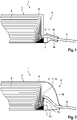
- the battery cell 1 according to a preferred first embodiment of the invention in the initial state A is shown schematically in a sectional view.
- the battery cell 1 has a cell wall 4, through which a cell interior 5 is formed and sealed airtight to the outside.
- Active material 6 is arranged in several layers in the cell interior 5 for storing and releasing electrical energy.
- the active material 6 is electrically coupled to the electrode 7 of the battery cell 1 .
- a conductor 8 of the battery cell 1 is led out of the cell interior 5 .
- the electrode 7 and the conductor 8 are compressed between a first wall section 4a of the cell wall 4 and a second wall section 4b of the cell wall 4 under the effect of a pressure difference between a cell internal pressure in the cell interior 5 and a cell external pressure outside of the cell interior 5 and are thus electrically coupled to one another.
- a detachment device 9 designed as a pressure device 11 is arranged in a tensioned state between the conductor 8 and the second wall section 4b.
- the pressure device 11 represents a counterforce to the pressure force due to the pressure difference.
- FIG 2 shows the battery cell 1 according to FIG 1 illustrated preferred first embodiment of the invention in the interrupted state U schematically in a sectional view.
- the interruption state U the pressure difference between the cell internal pressure and the cell external pressure is increased by increasing the cell internal pressure in such a way that the first cell wall section 4a is moved away from the second cell wall section 4b. Due to the lack of compressive force against the first cell wall section 4a and the second cell wall section 4b, the conductor 8 is moved away from the electrode 7 by means of the pressure device 11 having a compression spring 12. In this way, a gap 10 is formed between the electrode 7 and the conductor 8 and the electrical coupling between the electrode 7 and the conductor 8 is eliminated.
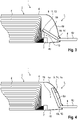
- the battery cell 1 according to a preferred second embodiment of the invention in the interrupted state U is shown schematically in a sectional view.
- the battery cell 1 according to the preferred second embodiment differs from the battery cell 1 according to the preferred first embodiment in the design of the pressure device 11 and the diverter 8 .
- the pressure device 11 has a pressure foam 13 instead of a pressure spring 12 .
- the conductor 8 has a joint section 8b designed as a kink 16.
- the battery cell 1 according to the preferred third embodiment differs from the battery cell 1 according to the preferred second embodiment in the design of the detachment device 9.
- the detachment device 9 has a holding device 14 with an adhesive point 15. The conductor 8 is held on the first wall section 4a via the adhesive point 15 and is thus moved along with it.
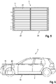
- the battery system 2 according to the preferred embodiment of the invention is shown schematically in a sectional view.
- the battery system 2 has a plurality of battery cells 1 according to the invention, which are combined to form a plurality of cell stacks 20 and are arranged within a system housing 17 of the battery system 2 .
- the cell stacks 20 are each braced by a bracing device 21 in the system housing 17 .
- Motor vehicle 3 has an electric drive system 18 with an electric motor 19 for driving motor vehicle 3, power electronics 22 for controlling electric motor 19, and a battery system 2 according to the invention for providing electrical energy for operating power electronics 22 and electric motor 19.
Landscapes
- Chemical & Material Sciences (AREA)
- Chemical Kinetics & Catalysis (AREA)
- Electrochemistry (AREA)
- General Chemical & Material Sciences (AREA)
- Engineering & Computer Science (AREA)
- Manufacturing & Machinery (AREA)
- Aviation & Aerospace Engineering (AREA)
- Materials Engineering (AREA)
- Battery Mounting, Suspending (AREA)
- Connection Of Batteries Or Terminals (AREA)
Abstract
Description
- Die vorliegende Erfindung betrifft eine Batteriezelle für ein Batteriesystem für ein Kraftfahrzeug. Ferner betrifft die Erfindung ein Batteriesystem für ein Kraftfahrzeug mit einer gattungsgemäßen Batteriezelle sowie ein Kraftfahrzeug mit einem gattungsgemäßen Batteriesystem.
- Es sind zylindrische sowie prismatische Batteriezellen bekannt, die zum Schutz der Batteriezelle, insbesondere vor einem thermischen Durchgehen, eine Sicherheitsvorrichtung, wie beispielsweise ein Current Interrupt Device (CID) oder ein Overcharging Safety Device (OSD), aufweisen. Üblicherweise weisen derartige Sicherheitsvorrichtungen eine Sicherheitsschaltung auf, welche bei einem kritischen Innendruck, einer kritischen Innentemperatur oder einer kritischen Gaskonzentration innerhalb der Zelle eine elektrische Kopplung zwischen dem Aktivmaterial der Batteriezelle, welches beispielsweise zu einem Zellwickel zusammengefasst ist, und einen aus der Batteriezelle herausgeführten elektrischen Pol unterbricht. Derartige Sicherheitsvorrichtungen sind für als Pouchzellen ausgebildete Batteriezellen derzeit nur sehr aufwendig umsetzbar.
- Aus der
DE 10 2016 110 778 A1 ist eine als Pouchzelle ausgebildete Batteriezelle mit einer Schutzvorrichtung bekannt, bei welcher eine elektrische Kopplung eines ersten Innenleiters der Batteriezelle mit einem zweiten Innenleiter der Batteriezelle in Abhängigkeit einer Ausdehnung der Batteriezelle trennbar ist. Hierfür ist der zweite Innenleiter an einer unteren Zellwandung gehalten, beispielsweise über eine Klebeschicht, und über einen Biegeabschnitt mit einem ersten Abschnitt des ersten Innenleiters elektrisch gekoppelt. Der erste Abschnitt ist an einer oberen Zellwandung der Batteriezelle gehalten, beispielsweise über eine Klebeschicht, und über eine Sollbruchstelle mit einem zweiten Abschnitt des ersten Innenleiters elektrisch gekoppelt. Der zweite Abschnitt ist über eine elektrisch isolierende Klebeschicht an dem zweiten Innenleiter gekoppelt. Bei einer kritischen Ausdehnung der Batteriezelle ist die obere Zellwandung derart von der unteren Zellwandung entfernt, dass der Biegeabschnitt zumindest teilweise plastisch verformt und die Sollbruchstelle aufgebrochen ist. Die elektrische Kopplung zwischen dem ersten Abschnitt und dem zweiten Abschnitt des ersten Innenleiters ist somit unterbrochen. Auf diese Weise ist die Batteriezelle automatisch von einem restlichen Batteriesystem abtrennbar. Der Biegebereich ist ausgebildet, bei einer Rückverformung der Batteriezelle etwas von der plastischen Verformung beizubehalten, sodass eine Unterbrechung der elektrischen Kopplung zwischen dem ersten Abschnitt und dem zweiten Abschnitt des ersten Innenleiters weiterhin bestehen bleibt. - Bekannte als Pouchzellen ausgebildete Batteriezellen mit einer Schutzvorrichtung haben den Nachteil, dass zum Unterbrechen der elektrischen Kopplung eine größere Verformung einer Zellwandung erforderlich ist. Dies ist insbesondere bei Batteriesystemen mit einer Druckvorrichtung problematisch, mittels welcher die Batteriezellen zur Steigerung der Leistungsfähigkeit sowie zur Erhöhung der Lebensdauer zusammendrückbar sind.
- Es ist daher Aufgabe der vorliegenden Erfindung, die voranstehend beschriebenen Nachteile bei eine Batteriezelle zu beheben oder zumindest teilweise zu beheben. Insbesondere ist es Aufgabe der vorliegenden Erfindung eine Batteriezelle, ein Batteriesystem und ein Kraftfahrzeug zu schaffen, die auf eine einfache und kostengünstige Art und Weise eine verbesserte Unterbrechung der elektrischen Kopplung einer defekten Batteriezelle zu weiteren Batteriezellen des Batteriesystems sicherstellen.
- Voranstehende Aufgabe wird durch die Patentansprüche gelöst. Demnach wird die Aufgabe durch eine Batteriezelle für ein Batteriesystem für ein Kraftfahrzeug mit den Merkmalen des unabhängigen Anspruchs 1, durch ein Batteriesystem für ein Kraftfahrzeug mit den Merkmalen des nebengeordneten Anspruchs 9 sowie durch ein Kraftfahrzeug mit den Merkmalen des nebengeordneten Anspruchs 10 gelöst.
- Weitere Merkmale und Details der Erfindung ergeben sich aus den Unteransprüchen, der Beschreibung und den Zeichnungen. Dabei gelten Merkmale und Details, die im Zusammenhang mit der erfindungsgemäßen Batteriezelle beschrieben sind, selbstverständlich auch im Zusammenhang mit dem erfindungsgemäßen Batteriesystem sowie dem erfindungsgemäßen Kraftfahrzeug und jeweils umgekehrt, sodass bezüglich der Offenbarung zu den einzelnen Erfindungsaspekten stets wechselseitig Bezug genommen wird beziehungsweise werden kann.
- Gemäß einem ersten Aspekt der Erfindung wird die Aufgabe durch eine Batteriezelle für ein Batteriesystem für ein Kraftfahrzeug gelöst. Die Batteriezelle weist eine flexible Zellwandung, einen von der Zellwandung gebildeten Zellinnenraum, in dem Zellinnenraum angeordnetes Aktivmaterial zum Speichern und Freigeben elektrischer Energie, eine im Zellinnenraum angeordnete, mit dem Aktivmaterial elektrisch gekoppelte Elektrode und einen aus dem Zellinnenraum herausragenden sowie in einem Ausgangszustand mit der Elektrode elektrisch gekoppelten Ableiter auf. Im Ausgangszustand ist ein Druckunterschied zwischen einem Zellinnendruck im Zellinnenraum und einem Zellaußendruck außerhalb des Zellinnenraums kleiner als ein vorgegebener Druckschwellwert. Erfindungsgemäß sind die Elektrode und der Ableiter im Ausgangszustand zur Herstellung der elektrischen Kopplung zwischen einem ersten Wandungsabschnitt und einem zweiten Wandungsabschnitt der Zellwandung gegeneinandergedrückt, wobei die Batteriezelle eine Ablösevorrichtung zum Aufheben der elektrischen Kopplung in einem Unterbrechungszustand aufweist. Der Druckunterschied entspricht im Unterbrechungszustand dem Druckschwellwert, wobei die Ablösevorrichtung ausgebildet ist, mit dem Ableiter oder der Elektrode vom Ausgangszustand in den Unterbrechungszustand einer Bewegung des ersten Wandungsabschnitts vom zweiten Wandungsabschnitt weg derart zu folgen, dass im Unterbrechungszustand zwischen dem Ableiter und der Elektrode ein Spalt ausgebildet ist.
- Das Batteriesystem ist vorzugsweise zum Betreiben eines Elektromotors und einer Leistungselektronik des Kraftfahrzeugs ausgebildet. Die Batteriezelle ist vorzugsweise als Pouchzelle ausgebildet. Die Zellwandung ist aus einem flexiblen Material gebildet, wie beispielsweise Aluminium oder dergleichen. Vorzugsweise ist die Zellwandung folienartig ausgebildet. Ferner weist die Zellwandung mindestens eine Naht zum Bilden eines nach außen abgedichteten Zellinnenraums auf. Die Naht ist vorzugsweise als Schweißnaht, Klebenaht oder dergleichen ausgebildet.
- Die Zellwandung ist flexibel ausgebildet und bildet den Zellinnenraum. Nahtstellen der Zellwandungen sind vorzugsweise durch Schweißen, Kleben oder dergleichen versiegelt, vorzugsweise derart, dass der Zellinnenraum gasdicht verschossen ist. Durch die flexible Ausbildung der Zellwandung ist der Zellinnenraum durch Erhöhung des Zellinnendrucks, beispielsweise durch aus dem Aktivmaterial austretendes Zellgas, insbesondere in Folge eines thermischen Durchgehens des Aktivmaterials, expandierbar. Die äußeren Abmessungen der Batteriezelle, wie beispielsweise eine Dicke, sind auf diese Weise vergrößerbar. Vorzugsweise weist die Zellwandung Aluminium auf oder ist aus Aluminium gebildet. Weiter bevorzugt weist die Zellwandung, insbesondere auf einer nach außen gerichteten Wandungsseite, besonders bevorzugt auf beiden Seiten, ein elektrisch isolierendes Material, insbesondere in Form einer durchgängigen Schicht, auf.
- Das Aktivmaterial ist im Zellinnenraum angeordnet. Unter einem Aktivmaterial wird im Rahmen der Erfindung ein Werkstoff bzw. ein Werkstoffgemisch verstanden, welches die Speicherung sowie Abgabe elektrischer Energie über Ableiter der Batteriezelle gewährleistet. Das Aktivmaterial weist vorzugsweise Lithiumionen auf. Das Aktivmaterial kann erfindungsgemäß in Schichtform, insbesondere gestapelt oder gefaltet, im Zellinnenraum angeordnet sein.
- Die Elektrode ist zum Bereitstellen der elektrischen Kopplung des Aktivmaterials mit dem Ableiter ausgebildet. Der Ableiter ist zum Bereitstellen der elektrischen Kopplung der Elektrode mit weiteren Komponenten des Batteriesystems, wie beispielsweise weiteren Batteriezellen, insbesondere im Rahmen einer Serienschaltung oder Reihenschaltung, oder einem Hauptableiter des Batteriesystems zum Abgeben elektrischer Energie an elektrische Verbraucher des Kraftfahrzeugs sowie zum Einleiten elektrischer Energie zum Aufladen der Batteriezellen ausgebildet. Zur Bereitstellung der elektrischen Kopplung weist die Ableitervorrichtung den ersten Ableiterabschnitt und den zweiten Ableiterabschnitt auf.
- Im Ausgangszustand ist der Zellinnendruck im Zellinnenraum geringer als der Zellaußendruck. Vorzugsweise ist der Zellinnendruck geringer als der Atmosphärendruck, besonders bevorzugt ist der Zellinnendruck als Vakuum ausgebildet, insbesondere als Feinvakuum oder Hochvakuum. Die Zellwandung ist vorzugsweise ausgebildet und abgedichtet, das Vakuum zu halten. Weiter bevorzugt entspricht der Zellaußendruck dem Atmosphärendruck. Die Elektrode und der Ableiter sind durch den zwischen dem Zellinnendruck und Zellaußendruck bestehenden Druckunterschied zwischen den ersten Wandungsabschnitt und den zweiten Wandungsabschnitt der Zellwandung gegeneinandergedrückt. Auf diese Weise ist eine zuverlässige sowie erschütterungsbeständige elektrische Kopplung zwischen der Elektrode und dem Ableiter sichergestellt. Ferner ist somit das Aktivmaterial der Batteriezelle mit dem Ableiter elektrisch gekoppelt.
- Die Ablösevorrichtung ist ausgebildet, im Unterbrechungszustand die elektrische Kopplung zwischen der Elektrode und dem Ableiter zu unterbrechen. Hierfür ist die Ablösevorrichtung ausgebildet, den Ableiter oder die Elektrode zusammen mit dem ersten Wandungsabschnitt von dem Ausgangszustand in den Unterbrechungszustand zu bewegen. Unter einem Unterbrechungszustand wird ein Zustand verstanden, bei welchem die elektrische Kopplung zwischen Elektrode und Ableiter vollständig unterbrochen ist. Eine weitere Entfernung sowie ein erneutes Annähern von Elektrode und Ableiter ohne Wiederherstellung der elektrischen Kopplung können im Rahmen der Erfindung ebenfalls als Unterbrechungszustand bezeichnet werden. Im Unterbrechungszustand ist bei einer nicht geöffneten Zellwandung der Zellinnendruck vorzugsweise größer als im Ausgangszustand. Ferner ist ein Abstand zwischen dem ersten Wandungsabschnitt und dem zweiten Wandungsabschnitt im Unterbrechungszustand größer als im Ausgangszustand. Auf diese Weise ist im Unterbrechungszustand ein Spalt zwischen der Elektrode und dem Ableiter ausgebildet. Die Ablösevorrichtung kann erfindungsgemäß als Komponente ohne mechanischen Energiespeicher oder Komponente mit mechanischem Energiespeicher ausgebildet sein. Der mechanische Energiespeicher ist ausgebildet, im Ausgangszustand Energie zu speichern und diese im Unterbrechungszustand freizugeben. Vorzugsweise weist die Ablösevorrichtung eine Rückstellsperre zum Verhindern einer Rückstellung vom Unterbrechungszustand in den Ausgangszustand auf. Auf diese Weise ist gewährleistet, dass ein selbstständiges erneutes elektrisches Koppeln der Batteriezelle nach einem selbstständigen elektrischen Entkoppeln vermieden ist.
- Der Druckschwellwert ist vorzugsweise in Abhängigkeit mechanischer sowie chemischer bzw. elektrochemischer Kennwerte der Batteriezelle festgelegt und bestimmt, bei welchem Druckunterschied eine Trennung der elektrischen Kopplung der Batteriezelle vom Rest des Batteriesystems erfolgen soll, um weitere Schäden an der Batteriezelle sowie am Batteriesystem zu vermeiden oder zumindest zu reduzieren. Der Druckschwellwert liegt vorzugsweise unter einem kritischen Druck bei welchem ein Öffnen der Nähte der Zellwandung droht. Auf diese Weise ist verhinderbar, dass Zellgas durch eine defekte Naht entweicht und somit der Druckschwellwert im Zellinnenraum nicht oder mit erheblicher Verzögerung, beispielsweise, wenn die Batteriezelle bereits thermisch durchgeht, erreicht wird.
- Die Batteriezelle weist vorzugsweise eine Signalvorrichtung auf, die zum Ausgeben eines Signals ausgebildet ist, wenn die Elektrode vom Ableiter elektrisch entkoppelt ist. Die Signalvorrichtung weist vorzugsweise einen feststehenden ersten elektrischen Kontakt sowie einen mit dem ersten Wandungsabschnitt mitbewegbaren zweiten elektrischen Kontakt auf. Im Ausgangszustand sind der erste elektrische Kontakt und der zweite elektrische Kontakt vorzugsweise voneinander getrennt. Im Unterbrechungszustand kontaktiert der erste elektrische Kontakt den zweiten elektrischen Kontakt vorzugsweise derart, dass ein Stromkreis geschlossen ist. Die Signalvorrichtung kann erfindungsgemäß innerhalb und/oder außerhalb der Batteriezelle angeordnet sein. Eine außerhalb der Batteriezelle angeordnete Signalvorrichtung hat den Vorteil, dass keine Signalleitungen aus der Batteriezelle herausgeführt werden müssen. Auf diese Weise ist das elektrische Abkoppeln einer konkreten Batteriezelle eines Batteriesystems zuverlässig sowie mit einfachen Mitteln und kostengünstig detektierbar.
- Eine erfindungsgemäße Batteriezelle hat gegenüber herkömmlichen Batteriezellen den Vorteil, dass mit einfachen Mitteln sowie auf eine kostengünstige Art und Weise eine Unterbrechung der elektrischen Kopplung zwischen der Elektrode und dem Ableiter automatisch bewirkbar ist, wenn das Verhältnis zwischen Zellinnendruck und Zellaußendruck einen kritischen Grenzwert übersteigt. Durch die Wirkkopplung der Ablösevorrichtung mit dem Druckunterschied von Zellinnendruck und Zellaußendruck sind eine Messung des Zellinnendrucks sowie eine Steuerungsvorrichtung zum Steuern der Aktuatorvorrichtung entbehrlich. Somit ist eine Komplexität des Batteriezellensystems erheblich reduziert und eine Betriebssicherheit der Batteriezelle gegenüber herkömmlichen Batteriezellen wesentlich verbessert.
- Gemäß einer bevorzugten Weiterentwicklung der Erfindung kann bei einer Batteriezelle vorgesehen sein, dass die Ablösevorrichtung eine Druckvorrichtung aufweist, wobei die Druckvorrichtung im Ausgangszustand eine durch den Druckunterschied aufrechterhaltene Vorspannung aufweist und ausgebildet ist, den Ableiter von der Elektrode wegweisend oder die Elektrode vom Ableiter wegweisend in Richtung des ersten Wandungsabschnitts zu drücken. Unter einer Druckvorrichtung wird im Rahmen der Erfindung eine Vorrichtung zur Speicherung mechanischer Energie verstanden. Die Druckvorrichtung ist ausgebildet, eine Druckkraft bereitzustellen, mittels welcher - bei Ausbleiben einer ausreichenden Gegenkraft - die Elektrode und der Ableiter voneinander weg bewegbar sind, beispielsweise durch Drücken gegen die Elektrode und/oder den Ableiter. Durch den Druckunterschied zwischen dem Zellaußendruck und dem Zellinnentruck im Ausgangszustand ist die Druckvorrichtung zusammengedrückt. Wenn der Druckunterschied derart abnimmt, dass der Druckschwellwert erreicht ist, ist die Druckvorrichtung zum Auseinanderdrücken von Elektrode und Ableiter expandierbar. Bei Verwendung einer Druckvorrichtung ist eine mechanische Entkopplung zum ersten Wandungsabschnitt möglich, sodass zwischen dem Ausgangszustand beispielsweise ein gemeinsames Bewegen vom ersten Wandungsabschnitt und dem Ableiter bzw. der Elektrode bis zum Unterbrechungszustand gewährleistet ist. Wenn die Druckvorrichtung einen entspannten Zustand erreich hat, könnte eine weitere Bewegung des ersten Wandungsabschnitt von der entspannten Druckvorrichtung weg weiterhin möglich sein. Dies hat den Vorteil, dass mit einfachen Mitteln sowie auf eine kostengünstige Art und Weise ein zuverlässiges elektrisches Entkoppeln von Elektrode und Ableiter realisierbar ist.
- Es ist erfindungsgemäß bevorzugt, dass die Druckvorrichtung eine Druckfeder und/oder einen Druckzylinder und/oder einen Druckschaum aufweist oder dass die Druckvorrichtung durch eine Eigenspannung des Ableiters oder der Elektrode realisiert ist. Eine Druckfeder ist vorzugsweise als Schraubenfeder ausgebildet. Ein Druckschaum ist ein poröses Material, welches unter Aufbau einer Druckspannung komprimierbar ist. Das poröse Material kann erfindungsgemäß offenporig und/oder geschlossenporig ausgebildet sein. Bei einer geschlossenporigen Ausbildung ist in den Poren vorzugsweise ein Inertgas, wie beispielsweise Stickstoff, Argon oder dergleichen, insbesondere mit einem Inertgasanteil von mindestens 95%, angeordnet. In einem Druckzylinder ist vorzugsweise ein Druckkolben angeordnet sowie translatorisch geführt. Ein Druckmedium im Druckzylinder ist vorzugsweise nicht brennbar bzw. nicht explosibel, wie beispielsweise ein Inertgas. Zur Bereitstellung der Eigenspannung weist der jeweilige Ableiter oder die Elektrode ein elastisches Material auf. Vorzugsweise ist der Ableiter bzw. die Elektrode hierfür gemäß einer Schenkelfeder ausgebildet. Eine derartige Druckvorrichtung ist mit einfachen Mitteln sowie auf eine kostengünstige Art und Weise herstellbar und vorspannbar. Zudem ist mittels einer derartigen Druckvorrichtung ein zuverlässiges Unterbrechen der elektrischen Kopplung zwischen der Elektrode und dem Ableiter gewährleistet.
- Weiter bevorzugt weist die Ablösevorrichtung eine Haltevorrichtung auf, wobei die Haltevorrichtung ausgebildet ist, den Ableiter oder die Elektrode am ersten Wandungsabschnitt zu halten. Mittels der Haltevorrichtung ist eine Bewegung des Ableiters bzw. der Elektrode mit dem ersten Wandungsabschnitt derart koppelbar, dass der Ableiter bzw. die Elektrode der Bewegung des ersten Wandungsabschnitts solange folgt, wie die Haltevorrichtung intakt ist. Demnach ist die Haltevorrichtung vorzugsweise derart ausgebildet, dass zumindest der Unterbrechungszustand erreichbar ist. Vorzugsweise ist die Haltevorrichtung ausgebildet, das Halten über eine gesamte Bewegungsfreiheit des ersten Wandungsabschnitts beim Ausdehnen des Zellinnenraums zu gewährleisten. Dies hat den Vorteil, dass mit einfachen Mitteln sowie auf eine kostengünstige Art und Weise ein elektrisches Entkoppeln von Elektrode und Ableiter beim Ausdehnen des Zellinnenraums gewährleistet ist.
- In einer besonders bevorzugten Ausgestaltung der Erfindung weist die Haltevorrichtung eine Klebestelle und/oder Lötstelle und/oder Schweißstelle und/oder Crimpstelle auf. Die Klebestelle weist vorzugsweise einen Klebstoff auf, der im Betriebstemperaturbereich der Batteriezelle sowie bei Temperaturen während des thermischen Durchgehens der Batteriezelle zumindest solange beständig ist, dass ein zuverlässiges elektrisches Entkoppeln von Elektrode und Ableiter beim Wegbewegen des ersten Wandungsabschnitts gewährleitstet ist. Alternativ kann die Haltevorrichtung eine Hakenvorrichtung zum Einhaken des Ableiters oder der Elektrode aufweisen. Dies hat den Vorteil, dass mit einfachen Mitteln sowie auf eine kostengünstige Art und Weise ein Halten am ersten Wandungsabschnitt und somit ein zuverlässiges elektrisches Entkoppeln von Elektrode und Ableiter gewährleistet ist.
- Vorzugsweise sind die Elektrode und der Ableiter im Ausgangszustand durch den zwischen dem Zellinnendruck und Zellaußendruck bestehenden Druckunterschied zwischen den ersten Wandungsabschnitt und den zweiten Wandungsabschnitt gegeneinandergedrückt. Hierbei wirkt der Druckunterschied gegen eine etwaige Druckvorrichtung derart, dass die Druckvorrichtung komprimiert und somit vorgespannt bleibt. Es kann erfindungsgemäß vorgesehen sein, dass die Zellwandung eine plastisch verformbare Stützvorrichtung aufweist. Die Stützvorrichtung ist vorzugsweise im Ausgangszustand sowie im Unterbrechungszustand spannungsfrei oder zumindest im Wesentlichen spannungsfrei und durch die Bewegung des ersten Wandungsabschnitts plastisch verformbar. Somit ist verhinderbar, dass die Zellwandung bei einem Druckausgleich zwischen dem Zellinnendruck und dem Zellaußendruck wieder kollabiert. Dies hat den Vorteil, dass mit einfachen Mitteln sowie auf eine kostengünstige Art und Weise eine zuverlässige elektrische Kopplung sowie Entkopplung von Elektrode und Ableiter gewährleistet ist.
- Gemäß einer bevorzugten Ausführungsform der Erfindung weist die Elektrode oder der Ableiter zwischen zwei Grundabschnitten einen Gelenkabschnitt zum Verbessern einer gemeinsamen Bewegung mit dem ersten Wandungsabschnitt auf. Der Gelenkabschnitt ist derart ausgebildet, dass die benachbarten Grundabschnitte beim Bewegen des ersten Wandungsabschnitts aus dem Ausgangszustand in den Unterbrechungszustand um eine durch den Gelenkabschnitt verlaufende Gelenkachse relativ zueinander verschwenkt werden. Durch den Gelenkabschnitt ist somit eine Bewegung besser vordefinierbar. Ferner hat ein Gelenkabschnitt den Vorteil, dass mit einfachen Mitteln sowie auf eine kostengünstige Art und Weise ein mechanischer Widerstand der Elektrode bzw. des Ableiters reduzierbar ist, sodass die gemeinsame Bewegung mit dem ersten Wandungsabschnitt verbessert ist.
- Besonders bevorzugt weist der Gelenkabschnitt einen Knick und/oder eine Querschnittsverringerung und/oder eine erhöhte Duktilität als die benachbarten Grundbereiche auf. Der Knick weist vorzugsweise einen Winkel von über 120° auf. Die Querschnittsverringerung beträgt vorzugsweise in eine Richtung zwischen 10% und 30% des Querschnitts. Die erhöhte Duktilität ist beispielsweise durch einen anderen Werkstoff oder eine lokale Wärmebehandlung bewirkbar. Dies hat den Vorteil, dass mit einfachen Mitteln sowie auf eine kostengünstige Art und Weise die gemeinsame Bewegung mit dem ersten Wandungsabschnitt verbessert ist.
- Gemäß einem zweiten Aspekt der Erfindung wird die Aufgabe durch ein Batteriesystem für ein Kraftfahrzeug gelöst. Das Batteriesystem weist ein Systemgehäuse auf. Erfindungsgemäß sind innerhalb des Systemgehäuses mehrere erfindungsgemäße Batteriezellen angeordnet. Das Systemgehäuse ist vorzugsweise aus einem verhältnismäßig steifen Material gebildet, um den Batteriezellen einen Schutz vor äußeren mechanischen Einflüssen, wie beispielsweise in Folge einer Kollision des Kraftfahrzeugs, bereitzustellen. Die Batteriezellen sind vorzugsweise miteinander elektrisch verschaltet, beispielsweise in einer Reihenschaltung und/oder Parallelschaltung. Die Batteriezellen sind vorzugsweise zu einem oder mehreren Batteriezellenstapeln zusammengefasst. Überdies weist das Batteriesystem vorzugsweise für einen oder mehrere, vorzugsweise sämtliche Batteriezellenstapel eine Druckvorrichtung zum Zusammendrücken der Batteriezellen des jeweiligen Batteriezellenstapels auf. Das Batteriesystem weist vorzugsweise zwei oder mehrere Hauptableiter zum elektrischen Koppeln des Batteriesystems mit dem Kraftfahrzeug auf. Das Batteriesystem ist vorzugsweise zum Betreiben eines Elektromotors und einer Leistungselektronik des Kraftfahrzeugs ausgebildet.
- Bei dem erfindungsgemäßen Batteriesystem ergeben sich sämtliche Vorteile, die bereits zu einer Batteriezelle gemäß dem ersten Aspekt der Erfindung beschrieben worden sind. Demnach hat das erfindungsgemäße Batteriesystem gegenüber herkömmlichen Batteriesystemen den Vorteil, dass mit einfachen Mitteln sowie auf eine kostengünstige Art und Weise eine Unterbrechung der elektrischen Kopplung zwischen der Elektrode und dem Ableiter automatisch bewirkbar ist, wenn das Verhältnis zwischen Zellinnendruck und Zellaußendruck einen kritischen Grenzwert übersteigt. Durch die Wirkkopplung der Ablösevorrichtung mit dem Druckunterschied von Zellinnendruck und Zellaußendruck sind eine Messung des Zellinnendrucks sowie eine Steuerungsvorrichtung zum Steuern der Aktuatorvorrichtung entbehrlich. Somit ist eine Komplexität des Batteriezellensystems erheblich reduziert und eine Betriebssicherheit des Batteriezellensystems gegenüber herkömmlichen Batteriezellensystemen wesentlich verbessert.
- Gemäß einem dritten Aspekt der Erfindung wird die Aufgabe durch ein Kraftfahrzeug gelöst. Das Kraftfahrzeug weist ein elektrisches Antriebssystem mit einem Elektromotor zum Antreiben des Kraftfahrzeugs auf. Erfindungsgemäß weist das Antriebssystem zum Versorgen des Elektromotors mit elektrischer Energie ein erfindungsgemäßes Batteriesystem auf. Das Batteriesystem ist mit dem Elektromotor elektrisch gekoppelt, vorzugsweise über eine Leistungselektronik zum Betreiben des Elektromotors. Erfindungsgemäß kann das Kraftfahrzeug mehrere Elektromotoren zum Antreiben des Kraftfahrzeugs aufweisen, insbesondere einen Elektromotor zum Antreiben einer Vorderachse des Kraftfahrzeugs und einen Elektromotor zum Antreiben einer Hinterachse des Kraftfahrzeugs.
- Bei dem erfindungsgemäßen Kraftfahrzeug ergeben sich sämtliche Vorteile, die bereits zu einer Batteriezelle gemäß dem ersten Aspekt der Erfindung sowie zu einem Batteriesystem gemäß dem zweiten Aspekt der Erfindung beschrieben worden sind. Demnach hat das erfindungsgemäße Kraftfahrzeug gegenüber herkömmlichen Kraftfahrzeugen den Vorteil, dass mit einfachen Mitteln sowie auf eine kostengünstige Art und Weise eine Unterbrechung der elektrischen Kopplung zwischen der Elektrode und dem Ableiter automatisch bewirkbar ist, wenn das Verhältnis zwischen Zellinnendruck und Zellaußendruck einen kritischen Grenzwert übersteigt. Durch die Wirkkopplung der Ablösevorrichtung mit dem Druckunterschied von Zellinnendruck und Zellaußendruck sind eine Messung des Zellinnendrucks sowie eine Steuerungsvorrichtung zum Steuern der Aktuatorvorrichtung entbehrlich. Somit ist eine Komplexität des Kraftfahrzeugs weiter reduziert und eine Betriebssicherheit des Kraftfahrzeugs gegenüber herkömmlichen Kraftfahrzeugen wesentlich verbessert.
- Eine erfindungsgemäße Batteriezelle, ein erfindungsgemäßes Batteriesystem sowie ein erfindungsgemäßes Kraftfahrzeug werden nachfolgend anhand von Zeichnungen näher erläutert. Es zeigen jeweils schematisch:
- Figur 1
- in einer Schnittdarstellung eine Batteriezelle gemäß einer bevorzugten ersten Ausführungsform der Erfindung in einem Ausgangszustand,
- Figur 2
- in einer Schnittdarstellung die Batteriezelle aus
Figur 1 in einem Unterbrechungszustand, - Figur 3
- in einer Schnittdarstellung eine Batteriezelle gemäß einer bevorzugten zweiten Ausführungsform der Erfindung in einem Unterbrechungszustand,
- Figur 4
- in einer Schnittdarstellung eine Batteriezelle gemäß einer bevorzugten dritten Ausführungsform der Erfindung in einem Unterbrechungszustand,
- Figur 5
- in einer Schnittdarstellung ein Batteriesystem gemäß einer bevorzugten Ausführungsform der Erfindung, und
- Figur 6
- in einer Seitenansicht eine bevorzugte Ausführungsform eines erfindungsgemäßen Kraftfahrzeugs.
- Elemente mit gleicher Funktion und Wirkungsweise sind in den
Figuren 1 bis 6 jeweils mit denselben Bezugszeichen versehen. - In
Fig. 1 ist die Batteriezelle 1 gemäß einer bevorzugten ersten Ausführungsform der Erfindung in dem Ausgangszustand A schematisch in einer Schnittdarstellung abgebildet. Die Batteriezelle 1 weist eine Zellwandung 4 auf, durch welche ein Zellinnenraum 5 gebildet und nach außen luftdicht abgedichtet ist. Im Zellinnenraum 5 ist zum Speichern und Abgeben elektrischer Energie Aktivmaterial 6 in mehreren Schichten angeordnet. Das Aktivmaterial 6 ist mit der Elektrode 7 der Batteriezelle 1 elektrisch gekoppelt. Ein Ableiter 8 der Batteriezelle 1 ist aus dem Zellinnenraum 5 herausgeführt. Die Elektrode 7 und der Ableiter 8 sind zwischen einem ersten Wandungsabschnitt 4a der Zellwandung 4 und einem zweiten Wandungsabschnitt 4b der Zellwandung 4 unter Einwirkung eines Druckunterschieds zwischen einem Zellinnendruck im Zellinnenraum 5 und einem Zellaußendruck außerhalb des Zellinnenraums 5 zusammengedrückt und somit miteinander elektrisch gekoppelt. Zwischen dem Ableiter 8 und dem zweiten Wandungsabschnitt 4b ist eine als Druckvorrichtung 11 ausgebildete Ablösevorrichtung 9 in einem gespannten Zustand angeordnet. Die Druckvorrichtung 11 stellt eine Gegenkraft zur Druckkraft aufgrund des Druckunterschieds dar. -
Fig. 2 zeigt die Batteriezelle 1 gemäß der inFig. 1 abgebildeten bevorzugten ersten Ausführungsform der Erfindung in dem Unterbrechungszustand U schematisch in einer Schnittdarstellung. In dem Unterbrechungszustand U ist der Druckunterschied zwischen dem Zellinnendruck und dem Zellaußendruck durch Erhöhung des Zellinnendrucks derart erhöht, dass der erste Zellwandungsabschnitt 4a vom zweiten Zellwandungsabschnitt 4b wegbewegt ist. Aufgrund der ausbleibenden Druckkraft gegen den ersten Zellwandungsabschnitt 4a und den zweiten Zellwandungsabschnitt 4b ist der Ableiter 8 mittels der eine Druckfeder 12 aufweisenden Druckvorrichtung 11 von der Elektrode 7 wegbewegt. Auf diese Weise ist zwischen der Elektrode 7 und dem Ableiter 8 ein Spalt 10 ausgebildet und die elektrische Kopplung zwischen der Elektrode 7 und dem Ableiter 8 aufgehoben. - In
Fig. 3 ist die Batteriezelle 1 gemäß einer bevorzugten zweiten Ausführungsform der Erfindung in dem Unterbrechungszustand U schematisch in einer Schnittdarstellung abgebildet. Die Batteriezelle 1 gemäß der bevorzugten zweiten Ausführungsform unterscheidet sich von der Batteriezelle 1 gemäß der bevorzugten ersten Ausführungsform in der Ausbildung der Druckvorrichtung 11 und des Ableiters 8. Die Druckvorrichtung 11 weist anstatt einer Druckfeder 12 einen Druckschaum 13 auf. Der Ableiter 8 weist zwischen zwei Grundabschnitten 8a einen als Knick 16 ausgebildeten Gelenkabschnitt 8b auf. -
Fig. 4 zeigt die Batteriezelle 1 gemäß der bevorzugten dritten Ausführungsform der Erfindung in dem Unterbrechungszustand U schematisch in einer Schnittdarstellung. Die Batteriezelle 1 gemäß der bevorzugten dritten Ausführungsform unterscheidet sich von der Batteriezelle 1 gemäß der bevorzugten zweiten Ausführungsform in der Ausbildung der Ablösevorrichtung 9. Die Ablösevorrichtung 9 weist eine Haltevorrichtung 14 mit einer Klebestelle 15 auf. Über die Klebestelle 15 ist der Ableiter 8 am ersten Wandungsabschnitt 4a gehalten und somit mit diesem mitbewegt. - In
Fig. 5 ist das Batteriesystem 2 gemäß der bevorzugten Ausführungsform der Erfindung schematisch in einer Schnittdarstellung abgebildet. Das Batteriesystem 2 weist eine Mehrzahl erfindungsgemäßer Batteriezellen 1 auf, die zu mehreren Zellstapeln 20 zusammengefasst und innerhalb eines Systemgehäuses 17 des Batteriesystems 2 angeordnet sind. Die Zellstapel 20 sind jeweils über eine Verspannvorrichtung 21 im Systemgehäuse 17 verspannt. -
Fig. 6 zeigt die bevorzugte Ausführungsform des erfindungsgemäßen Kraftfahrzeugs 3 schematisch in einer Seitenansicht. Das Kraftfahrzeug 3 weist ein elektrisches Antriebssystem 18 mit einem Elektromotor 19 zum Antreiben des Kraftfahrzeugs 3, einer Leistungselektronik 22 zum Steuern des Elektromotors 19 sowie einem erfindungsgemäßen Batteriesystem 2 zum Bereitstellen elektrischer Energie zum Betreiben der Leistungselektronik 22 und des Elektromotors 19 auf. -
- 1
- Batteriezelle
- 2
- Batteriesystem
- 3
- Kraftfahrzeug
- 4
- Zellwandung
- 4a
- erster Wandungsabschnitt
- 4b
- zweiter Wandungsabschnitt
- 5
- Zellinnenraum
- 6
- Aktivmaterial
- 7
- Elektrode
- 8
- Ableiter
- 8a
- Grundabschnitt
- 8b
- Gelenkabschnitt
- 9
- Ablösevorrichtung
- 10
- Spalt
- 11
- Druckvorrichtung
- 12
- Druckfeder
- 13
- Druckschaum
- 14
- Haltevorrichtung
- 15
- Klebestelle
- 16
- Knick
- 17
- Systemgehäuse
- 18
- Antriebssystem
- 19
- Elektromotor
- 20
- Zellstapel
- 21
- Verspannvorrichtung
- 22
- Leistungselektronik
- A
- Ausgangszustand
- U
- Unterbrechungszustand
Claims (10)
- Batteriezelle (1) für ein Batteriesystem (2) für ein Kraftfahrzeug (3), aufweisend eine flexible Zellwandung (4), einen von der Zellwandung (4) gebildeten Zellinnenraum (5), in dem Zellinnenraum (5) angeordnetes Aktivmaterial (6) zum Speichern und Freigeben elektrischer Energie, eine im Zellinnenraum (5) angeordnete, mit dem Aktivmaterial (6) elektrisch gekoppelte Elektrode (7) und einen aus dem Zellinnenraum (5) herausragenden sowie in einem Ausgangszustand (A) mit der Elektrode (7) elektrisch gekoppelten Ableiter (8), wobei im Ausgangszustand (A) ein Druckunterschied zwischen einem Zellinnendruck im Zellinnenraum (5) und einem Zellaußendruck außerhalb des Zellinnenraums (5) kleiner ist als ein vorgegebener Druckschwellwert,
dadurch gekennzeichnet,
dass die Elektrode (7) und der Ableiter (8) im Ausgangszustand (A) zur Herstellung der elektrischen Kopplung zwischen einen ersten Wandungsabschnitt (4a) und einen zweiten Wandungsabschnitt (4b) der Zellwandung (4) gegeneinander gedrückt sind, wobei die Batteriezelle (1) eine Ablösevorrichtung (9) zum Aufheben der elektrischen Kopplung in einem Unterbrechungszustand (U) aufweist, wobei der Druckunterschied im Unterbrechungszustand (U) dem Druckschwellwert entspricht, wobei die Ablösevorrichtung (9) ausgebildet ist, mit dem Ableiter (8) oder der Elektrode (7) vom Ausgangszustand (A) in den Unterbrechungszustand (U) einer Bewegung des ersten Wandungsabschnitts (4a) vom zweiten Wandungsabschnitt (4b) weg derart zu folgen, dass im Unterbrechungszustand (U) zwischen dem Ableiter (8) und der Elektrode (7) ein Spalt (10) ausgebildet ist. - Batteriezelle (1) nach Anspruch 1,
dadurch gekennzeichnet,
dass die Ablösevorrichtung (9) eine Druckvorrichtung (11) aufweist, wobei die Druckvorrichtung (11) im Ausgangszustand (A) eine durch den Druckunterschied aufrechterhaltene Vorspannung aufweist und ausgebildet ist, den Ableiter (8) von der Elektrode (7) wegweisend oder die Elektrode (7) vom Ableiter (8) wegweisend in Richtung des ersten Wandungsabschnitts (4a) zu drücken. - Batteriezelle (1) nach Anspruch 2,
dadurch gekennzeichnet,
dass die Druckvorrichtung (11) eine Druckfeder (12) und/oder einen Druckzylinder und/oder einen Druckschaum (13) aufweist oder dass die Druckvorrichtung (11) durch eine Eigenspannung des Ableiters (8) oder der Elektrode (7) realisiert ist. - Batteriezelle (1) nach einem der vorangegangenen Ansprüche,
dadurch gekennzeichnet,
dass die Ablösevorrichtung (9) eine Haltevorrichtung (14) aufweist, wobei die Haltevorrichtung (14) ausgebildet ist, den Ableiter (8) oder die Elektrode (7) am ersten Wandungsabschnitt (4a) zu halten. - Batteriezelle (1) nach Anspruch 4,
dadurch gekennzeichnet,
dass die Haltevorrichtung (14) eine Klebestelle (15) und/oder Lötstelle und/oder Schweißstelle und/oder Crimpstelle aufweist. - Batteriezelle (1) nach einem der vorangegangenen Ansprüche,
dadurch gekennzeichnet,
dass die Elektrode (7) und der Ableiter (8) im Ausgangszustand (A) durch den zwischen dem Zellinnendruck und Zellaußendruck bestehenden Druckunterschied zwischen den ersten Wandungsabschnitt (4a) und den zweiten Wandungsabschnitt (4b) gegeneinandergedrückt sind. - Batteriezelle (1) nach einem der vorangegangenen Ansprüche,
dadurch gekennzeichnet,
dass die Elektrode (7) oder der Ableiter (8) zwischen zwei Grundabschnitten (8a) einen Gelenkabschnitt (8b) zum Verbessern einer gemeinsamen Bewegung mit dem ersten Wandungsabschnitt (4a) aufweist. - Batteriezelle (1) nach Anspruch 7,
dadurch gekennzeichnet,
dass der Gelenkabschnitt (8b) einen Knick (16) und/oder eine Querschnittsverringerung und/oder eine erhöhte Duktilität als die benachbarten Grundabschnitte (8a) aufweist. - Batteriesystem (2) für ein Kraftfahrzeug (3), aufweisend ein Systemgehäuse (17),
dadurch gekennzeichnet,
dass im Systemgehäuse (17) mehrere Batteriezellen (1) nach einem der vorangegangenen Ansprüche angeordnet sind. - Kraftfahrzeug (3), aufweisend ein elektrisches Antriebssystem (18) mit einem Elektromotor (19) zum Antreiben des Kraftfahrzeugs (3),
dadurch gekennzeichnet,
dass das Antriebssystem (18) zum Versorgen des Elektromotors (19) mit elektrischer Energie ein Batteriesystem (2) nach Anspruch 9 aufweist.
Applications Claiming Priority (1)
| Application Number | Priority Date | Filing Date | Title |
|---|---|---|---|
| DE102021104716.1A DE102021104716A1 (de) | 2021-02-26 | 2021-02-26 | Batteriezelle mit Klemmkontakt, Batteriesystem und Kraftfahrzeug |
Publications (3)
| Publication Number | Publication Date |
|---|---|
| EP4050703A2 true EP4050703A2 (de) | 2022-08-31 |
| EP4050703A3 EP4050703A3 (de) | 2023-06-28 |
| EP4050703B1 EP4050703B1 (de) | 2025-04-09 |
Family
ID=80447429
Family Applications (1)
| Application Number | Title | Priority Date | Filing Date |
|---|---|---|---|
| EP22155940.4A Active EP4050703B1 (de) | 2021-02-26 | 2022-02-09 | Batteriezelle mit klemmkontakt, batteriesystem und kraftfahrzeug |
Country Status (3)
| Country | Link |
|---|---|
| EP (1) | EP4050703B1 (de) |
| CN (1) | CN114976523B (de) |
| DE (1) | DE102021104716A1 (de) |
Citations (1)
| Publication number | Priority date | Publication date | Assignee | Title |
|---|---|---|---|---|
| DE102016110778A1 (de) | 2015-10-16 | 2017-04-20 | Hyundai Motor Company | Batteriezelle |
Family Cites Families (10)
| Publication number | Priority date | Publication date | Assignee | Title |
|---|---|---|---|---|
| JP2004031193A (ja) * | 2002-06-27 | 2004-01-29 | Nissan Motor Co Ltd | 組電池 |
| DE102012016022A1 (de) * | 2012-08-13 | 2014-03-13 | Li-Tec Battery Gmbh | Wandlerzelle mit einem Zellgehäuse, Batterie mit wenigstens zwei dieser Wandlerzellen und Verfahren zum Herstellen einer Wandlerzelle |
| KR101991058B1 (ko) * | 2014-10-28 | 2019-06-19 | 주식회사 엘지화학 | 파우치형 이차전지 및 그의 제조방법 |
| KR101818630B1 (ko) * | 2015-04-22 | 2018-01-15 | 주식회사 엘지화학 | 안전성이 향상된 이차전지 |
| US10741822B2 (en) * | 2015-05-07 | 2020-08-11 | Lg Chem, Ltd. | Pouch-type secondary battery including electrode lead having electrical current limiting function |
| EP3159952B1 (de) * | 2015-10-19 | 2019-12-11 | Robert Bosch Gmbh | Sicherheitsvorrichtung für batteriesysteme |
| KR20180033972A (ko) | 2016-09-27 | 2018-04-04 | 현대자동차주식회사 | 배터리 셀 |
| KR102268402B1 (ko) * | 2017-08-29 | 2021-06-24 | 주식회사 엘지에너지솔루션 | 파우치 형 이차 전지 |
| KR102270866B1 (ko) * | 2017-11-24 | 2021-07-01 | 주식회사 엘지에너지솔루션 | 이차전지 |
| DE102019103614B4 (de) * | 2019-02-13 | 2021-01-07 | Bayerische Motoren Werke Aktiengesellschaft | Überstromschutzvorrichtung für eine Energiespeicherzelle, Elektrode für eine Energiespeicherzelle, Energiespeicherzelle und Verfahren zur Herstellung einer Elektrode für eine Energiespeicherzelle |
-
2021
- 2021-02-26 DE DE102021104716.1A patent/DE102021104716A1/de active Pending
-
2022
- 2022-02-09 EP EP22155940.4A patent/EP4050703B1/de active Active
- 2022-02-25 CN CN202210177116.7A patent/CN114976523B/zh active Active
Patent Citations (1)
| Publication number | Priority date | Publication date | Assignee | Title |
|---|---|---|---|---|
| DE102016110778A1 (de) | 2015-10-16 | 2017-04-20 | Hyundai Motor Company | Batteriezelle |
Also Published As
| Publication number | Publication date |
|---|---|
| CN114976523B (zh) | 2024-10-18 |
| DE102021104716A1 (de) | 2022-09-01 |
| CN114976523A (zh) | 2022-08-30 |
| EP4050703A3 (de) | 2023-06-28 |
| EP4050703B1 (de) | 2025-04-09 |
Similar Documents
| Publication | Publication Date | Title |
|---|---|---|
| DE112012006312B4 (de) | Abgedichtete Sekundärbatterie | |
| DE69829711T2 (de) | Lithium Sekundärbatterie | |
| EP2791991B1 (de) | Batteriezelle, batterie, kraftfahrzeug | |
| EP2606520B1 (de) | Elektrochemische zelle mit wenigstens einer druckentlastungsvorrichtung | |
| WO2017139826A1 (de) | Batterie | |
| WO2014016382A2 (de) | Batterie mit thermoschalter | |
| DE102018113815A1 (de) | Energiespeichersystem | |
| EP3443603A1 (de) | Druckentlastungsvorrichtung für ein batteriegehäuse, batteriegehäuse mit der druckentlastungsvorrichtung, batterie sowie verfahren zur druckentlastung einer batterie | |
| WO2014032768A9 (de) | Elektrochemische energiespeicherzelle und elektrochemische energiespeichervorrichtung mit wenigstens einer solchen elektrochemischen energiespeicherzelle | |
| DE102022103728B3 (de) | Batteriezelle | |
| DE102012208470A1 (de) | Vorrichtung und Verfahren zum Abkoppeln und/oder Überbrücken von Anschlüssen für eine Batteriezelle | |
| DE102010012935A1 (de) | Batterie, insbesondere Fahrzeugbatterie | |
| EP2467886A1 (de) | Elektrochemische zelle | |
| DE102019204105A1 (de) | Batteriezelle mit einer verbesserten Kühlung | |
| DE102007020905B4 (de) | Galvanisches Element mit Sicherungsmittel | |
| EP4050703B1 (de) | Batteriezelle mit klemmkontakt, batteriesystem und kraftfahrzeug | |
| WO2014040676A1 (de) | Batterieeinzelzelle f?r eine hv-batterie | |
| WO2016071100A1 (de) | Batterie mit verbesserter sicherheit | |
| EP2606522A1 (de) | Elektrochemische zelle mit wenigstens einer druckentlastungsvorrichtung | |
| DE102010013031A1 (de) | Batterie mit einem Zellenstapel von Batterieeinzelzellen | |
| DE102008059958B4 (de) | Einzelzelle und Batterie mit einer Mehrzahl elektrisch seriell und/oder parallel miteinander verbundener Einzelzellen | |
| EP4135088A1 (de) | Energiespeicherelement, verbund aus energiespeicherelementen und herstellungsverfahren | |
| EP4050698A2 (de) | Batteriezelle mit trennvorrichtung, batteriesystem und kraftfahrzeug | |
| DE102012005788A1 (de) | Wandlerzelle mit einem Zellgehäuse, Batterie mit zumindest zwei dieser Wandlerzellen und Verfahren zum Herstellen einer Wandlerzelle | |
| DE102020118846A1 (de) | Batteriezelle und Batteriemodul |
Legal Events
| Date | Code | Title | Description |
|---|---|---|---|
| PUAI | Public reference made under article 153(3) epc to a published international application that has entered the european phase |
Free format text: ORIGINAL CODE: 0009012 |
|
| STAA | Information on the status of an ep patent application or granted ep patent |
Free format text: STATUS: THE APPLICATION HAS BEEN PUBLISHED |
|
| AK | Designated contracting states |
Kind code of ref document: A2 Designated state(s): AL AT BE BG CH CY CZ DE DK EE ES FI FR GB GR HR HU IE IS IT LI LT LU LV MC MK MT NL NO PL PT RO RS SE SI SK SM TR |
|
| REG | Reference to a national code |
Ref country code: DE Ref legal event code: R079 Free format text: PREVIOUS MAIN CLASS: H01M0010650000 Ipc: H01M0050105000 Ref document number: 502022003476 Country of ref document: DE |
|
| PUAL | Search report despatched |
Free format text: ORIGINAL CODE: 0009013 |
|
| AK | Designated contracting states |
Kind code of ref document: A3 Designated state(s): AL AT BE BG CH CY CZ DE DK EE ES FI FR GB GR HR HU IE IS IT LI LT LU LV MC MK MT NL NO PL PT RO RS SE SI SK SM TR |
|
| RIC1 | Information provided on ipc code assigned before grant |
Ipc: H01M 50/578 20210101ALI20230525BHEP Ipc: H01M 50/105 20210101AFI20230525BHEP |
|
| STAA | Information on the status of an ep patent application or granted ep patent |
Free format text: STATUS: REQUEST FOR EXAMINATION WAS MADE |
|
| 17P | Request for examination filed |
Effective date: 20240102 |
|
| RBV | Designated contracting states (corrected) |
Designated state(s): AL AT BE BG CH CY CZ DE DK EE ES FI FR GB GR HR HU IE IS IT LI LT LU LV MC MK MT NL NO PL PT RO RS SE SI SK SM TR |
|
| GRAP | Despatch of communication of intention to grant a patent |
Free format text: ORIGINAL CODE: EPIDOSNIGR1 |
|
| STAA | Information on the status of an ep patent application or granted ep patent |
Free format text: STATUS: GRANT OF PATENT IS INTENDED |
|
| INTG | Intention to grant announced |
Effective date: 20241010 |
|
| RIN1 | Information on inventor provided before grant (corrected) |
Inventor name: MISIR, ONUR Inventor name: WESCHE, FRANK Inventor name: ARNDT, CAROLIN Inventor name: KLINK, MARCUS Inventor name: HENNIG, JAKOB Inventor name: LACKENMACHER, LUTZ |
|
| GRAS | Grant fee paid |
Free format text: ORIGINAL CODE: EPIDOSNIGR3 |
|
| GRAA | (expected) grant |
Free format text: ORIGINAL CODE: 0009210 |
|
| STAA | Information on the status of an ep patent application or granted ep patent |
Free format text: STATUS: THE PATENT HAS BEEN GRANTED |
|
| RAP1 | Party data changed (applicant data changed or rights of an application transferred) |
Owner name: POWERCO SE |
|
| AK | Designated contracting states |
Kind code of ref document: B1 Designated state(s): AL AT BE BG CH CY CZ DE DK EE ES FI FR GB GR HR HU IE IS IT LI LT LU LV MC MK MT NL NO PL PT RO RS SE SI SK SM TR |
|
| REG | Reference to a national code |
Ref country code: GB Ref legal event code: FG4D Free format text: NOT ENGLISH |
|
| REG | Reference to a national code |
Ref country code: CH Ref legal event code: EP |
|
| REG | Reference to a national code |
Ref country code: DE Ref legal event code: R096 Ref document number: 502022003476 Country of ref document: DE |
|
| REG | Reference to a national code |
Ref country code: IE Ref legal event code: FG4D Free format text: LANGUAGE OF EP DOCUMENT: GERMAN |
|
| P01 | Opt-out of the competence of the unified patent court (upc) registered |
Free format text: CASE NUMBER: APP_17073/2025 Effective date: 20250408 |
|
| REG | Reference to a national code |
Ref country code: DE Ref legal event code: R082 Ref document number: 502022003476 Country of ref document: DE |
|
| REG | Reference to a national code |
Ref country code: NL Ref legal event code: MP Effective date: 20250409 |
|
| PG25 | Lapsed in a contracting state [announced via postgrant information from national office to epo] |
Ref country code: NL Free format text: LAPSE BECAUSE OF FAILURE TO SUBMIT A TRANSLATION OF THE DESCRIPTION OR TO PAY THE FEE WITHIN THE PRESCRIBED TIME-LIMIT Effective date: 20250409 |
|
| PG25 | Lapsed in a contracting state [announced via postgrant information from national office to epo] |
Ref country code: FI Free format text: LAPSE BECAUSE OF FAILURE TO SUBMIT A TRANSLATION OF THE DESCRIPTION OR TO PAY THE FEE WITHIN THE PRESCRIBED TIME-LIMIT Effective date: 20250409 Ref country code: ES Free format text: LAPSE BECAUSE OF FAILURE TO SUBMIT A TRANSLATION OF THE DESCRIPTION OR TO PAY THE FEE WITHIN THE PRESCRIBED TIME-LIMIT Effective date: 20250409 Ref country code: PT Free format text: LAPSE BECAUSE OF FAILURE TO SUBMIT A TRANSLATION OF THE DESCRIPTION OR TO PAY THE FEE WITHIN THE PRESCRIBED TIME-LIMIT Effective date: 20250811 |
|
| REG | Reference to a national code |
Ref country code: LT Ref legal event code: MG9D |
|
| PG25 | Lapsed in a contracting state [announced via postgrant information from national office to epo] |
Ref country code: GR Free format text: LAPSE BECAUSE OF FAILURE TO SUBMIT A TRANSLATION OF THE DESCRIPTION OR TO PAY THE FEE WITHIN THE PRESCRIBED TIME-LIMIT Effective date: 20250710 Ref country code: NO Free format text: LAPSE BECAUSE OF FAILURE TO SUBMIT A TRANSLATION OF THE DESCRIPTION OR TO PAY THE FEE WITHIN THE PRESCRIBED TIME-LIMIT Effective date: 20250709 |
|
| PG25 | Lapsed in a contracting state [announced via postgrant information from national office to epo] |
Ref country code: PL Free format text: LAPSE BECAUSE OF FAILURE TO SUBMIT A TRANSLATION OF THE DESCRIPTION OR TO PAY THE FEE WITHIN THE PRESCRIBED TIME-LIMIT Effective date: 20250409 |
|
| PG25 | Lapsed in a contracting state [announced via postgrant information from national office to epo] |
Ref country code: BG Free format text: LAPSE BECAUSE OF FAILURE TO SUBMIT A TRANSLATION OF THE DESCRIPTION OR TO PAY THE FEE WITHIN THE PRESCRIBED TIME-LIMIT Effective date: 20250409 |
|
| PG25 | Lapsed in a contracting state [announced via postgrant information from national office to epo] |
Ref country code: HR Free format text: LAPSE BECAUSE OF FAILURE TO SUBMIT A TRANSLATION OF THE DESCRIPTION OR TO PAY THE FEE WITHIN THE PRESCRIBED TIME-LIMIT Effective date: 20250409 |
|
| PG25 | Lapsed in a contracting state [announced via postgrant information from national office to epo] |
Ref country code: RS Free format text: LAPSE BECAUSE OF FAILURE TO SUBMIT A TRANSLATION OF THE DESCRIPTION OR TO PAY THE FEE WITHIN THE PRESCRIBED TIME-LIMIT Effective date: 20250709 |
|
| PG25 | Lapsed in a contracting state [announced via postgrant information from national office to epo] |
Ref country code: IS Free format text: LAPSE BECAUSE OF FAILURE TO SUBMIT A TRANSLATION OF THE DESCRIPTION OR TO PAY THE FEE WITHIN THE PRESCRIBED TIME-LIMIT Effective date: 20250809 |
|
| PG25 | Lapsed in a contracting state [announced via postgrant information from national office to epo] |
Ref country code: LV Free format text: LAPSE BECAUSE OF FAILURE TO SUBMIT A TRANSLATION OF THE DESCRIPTION OR TO PAY THE FEE WITHIN THE PRESCRIBED TIME-LIMIT Effective date: 20250409 |
|
| REG | Reference to a national code |
Ref country code: DE Ref legal event code: R097 Ref document number: 502022003476 Country of ref document: DE |
|
| PG25 | Lapsed in a contracting state [announced via postgrant information from national office to epo] |
Ref country code: SM Free format text: LAPSE BECAUSE OF FAILURE TO SUBMIT A TRANSLATION OF THE DESCRIPTION OR TO PAY THE FEE WITHIN THE PRESCRIBED TIME-LIMIT Effective date: 20250409 Ref country code: DK Free format text: LAPSE BECAUSE OF FAILURE TO SUBMIT A TRANSLATION OF THE DESCRIPTION OR TO PAY THE FEE WITHIN THE PRESCRIBED TIME-LIMIT Effective date: 20250409 |
|
| PG25 | Lapsed in a contracting state [announced via postgrant information from national office to epo] |
Ref country code: CZ Free format text: LAPSE BECAUSE OF FAILURE TO SUBMIT A TRANSLATION OF THE DESCRIPTION OR TO PAY THE FEE WITHIN THE PRESCRIBED TIME-LIMIT Effective date: 20250409 |
|
| PG25 | Lapsed in a contracting state [announced via postgrant information from national office to epo] |
Ref country code: EE Free format text: LAPSE BECAUSE OF FAILURE TO SUBMIT A TRANSLATION OF THE DESCRIPTION OR TO PAY THE FEE WITHIN THE PRESCRIBED TIME-LIMIT Effective date: 20250409 |
|
| PG25 | Lapsed in a contracting state [announced via postgrant information from national office to epo] |
Ref country code: SK Free format text: LAPSE BECAUSE OF FAILURE TO SUBMIT A TRANSLATION OF THE DESCRIPTION OR TO PAY THE FEE WITHIN THE PRESCRIBED TIME-LIMIT Effective date: 20250409 |
|
| PG25 | Lapsed in a contracting state [announced via postgrant information from national office to epo] |
Ref country code: IT Free format text: LAPSE BECAUSE OF FAILURE TO SUBMIT A TRANSLATION OF THE DESCRIPTION OR TO PAY THE FEE WITHIN THE PRESCRIBED TIME-LIMIT Effective date: 20250409 |
|
| PLBE | No opposition filed within time limit |
Free format text: ORIGINAL CODE: 0009261 |
|
| STAA | Information on the status of an ep patent application or granted ep patent |
Free format text: STATUS: NO OPPOSITION FILED WITHIN TIME LIMIT |
|
| REG | Reference to a national code |
Ref country code: CH Ref legal event code: L10 Free format text: ST27 STATUS EVENT CODE: U-0-0-L10-L00 (AS PROVIDED BY THE NATIONAL OFFICE) Effective date: 20260218 |
|
| 26N | No opposition filed |
Effective date: 20260112 |
|
| PGFP | Annual fee paid to national office [announced via postgrant information from national office to epo] |
Ref country code: DE Payment date: 20260228 Year of fee payment: 5 |
|
| PGFP | Annual fee paid to national office [announced via postgrant information from national office to epo] |
Ref country code: AT Payment date: 20260301 Year of fee payment: 5 |