EP4050388B1 - Optical fiber and optical cable - Google Patents
Optical fiber and optical cable Download PDFInfo
- Publication number
- EP4050388B1 EP4050388B1 EP20878082.5A EP20878082A EP4050388B1 EP 4050388 B1 EP4050388 B1 EP 4050388B1 EP 20878082 A EP20878082 A EP 20878082A EP 4050388 B1 EP4050388 B1 EP 4050388B1
- Authority
- EP
- European Patent Office
- Prior art keywords
- less
- core
- refractive index
- optical
- mode
- Prior art date
- Legal status (The legal status is an assumption and is not a legal conclusion. Google has not performed a legal analysis and makes no representation as to the accuracy of the status listed.)
- Active
Links
Images

Classifications
-
- G—PHYSICS
- G02—OPTICS
- G02B—OPTICAL ELEMENTS, SYSTEMS OR APPARATUS
- G02B6/00—Light guides; Structural details of arrangements comprising light guides and other optical elements, e.g. couplings
- G02B6/02—Optical fibres with cladding with or without a coating
- G02B6/02004—Optical fibres with cladding with or without a coating characterised by the core effective area or mode field radius
-
- G—PHYSICS
- G02—OPTICS
- G02B—OPTICAL ELEMENTS, SYSTEMS OR APPARATUS
- G02B6/00—Light guides; Structural details of arrangements comprising light guides and other optical elements, e.g. couplings
- G02B6/02—Optical fibres with cladding with or without a coating
- G02B6/02295—Microstructured optical fibre
- G02B6/023—Microstructured optical fibre having different index layers arranged around the core for guiding light by reflection, i.e. 1D crystal, e.g. omniguide
-
- G—PHYSICS
- G02—OPTICS
- G02B—OPTICAL ELEMENTS, SYSTEMS OR APPARATUS
- G02B6/00—Light guides; Structural details of arrangements comprising light guides and other optical elements, e.g. couplings
- G02B6/02—Optical fibres with cladding with or without a coating
- G02B6/02004—Optical fibres with cladding with or without a coating characterised by the core effective area or mode field radius
- G02B6/02009—Large effective area or mode field radius, e.g. to reduce nonlinear effects in single mode fibres
- G02B6/02023—Based on higher order modes, i.e. propagating modes other than the LP01 or HE11 fundamental mode
-
- G—PHYSICS
- G02—OPTICS
- G02B—OPTICAL ELEMENTS, SYSTEMS OR APPARATUS
- G02B6/00—Light guides; Structural details of arrangements comprising light guides and other optical elements, e.g. couplings
- G02B6/02—Optical fibres with cladding with or without a coating
- G02B6/02214—Optical fibres with cladding with or without a coating tailored to obtain the desired dispersion, e.g. dispersion shifted, dispersion flattened
- G02B6/02285—Characterised by the polarisation mode dispersion [PMD] properties, e.g. for minimising PMD
-
- G—PHYSICS
- G02—OPTICS
- G02B—OPTICAL ELEMENTS, SYSTEMS OR APPARATUS
- G02B6/00—Light guides; Structural details of arrangements comprising light guides and other optical elements, e.g. couplings
- G02B6/02—Optical fibres with cladding with or without a coating
- G02B6/02395—Glass optical fibre with a protective coating, e.g. two layer polymer coating deposited directly on a silica cladding surface during fibre manufacture
-
- G—PHYSICS
- G02—OPTICS
- G02B—OPTICAL ELEMENTS, SYSTEMS OR APPARATUS
- G02B6/00—Light guides; Structural details of arrangements comprising light guides and other optical elements, e.g. couplings
- G02B6/02—Optical fibres with cladding with or without a coating
- G02B6/036—Optical fibres with cladding with or without a coating core or cladding comprising multiple layers
- G02B6/03616—Optical fibres characterised both by the number of different refractive index layers around the central core segment, i.e. around the innermost high index core layer, and their relative refractive index difference
- G02B6/03622—Optical fibres characterised both by the number of different refractive index layers around the central core segment, i.e. around the innermost high index core layer, and their relative refractive index difference having 2 layers only
- G02B6/03627—Optical fibres characterised both by the number of different refractive index layers around the central core segment, i.e. around the innermost high index core layer, and their relative refractive index difference having 2 layers only arranged - +
Definitions
- an optical communication system including a combination of an optical cable and an optical transceiver
- a ratio of system transmission performance to a cost required for system construction is maximized.
- an erbium doped fiber amplifier (EDFA) having excellent cost effectiveness is adopted due to a need for an optical amplifier.
- An optical cable including a plurality of single mode fibers (hereinafter, referred to as "SMF") for a wavelength band of 1530 nm or more and 1625 nm or less is adopted as a transmission medium.
- SMF single mode fibers
- Patent Document 1 discloses an optical fiber capable of performing a single mode operation in a short wavelength band such as a wavelength band of 850 nm, a wavelength band of 980 nm, or a wavelength band of 1060 nm, and having a large effective area of 30 ⁇ m 2 or more and 110 ⁇ m 2 or less in the short wavelength band.
- the inventors have found the following problems as a result of examining the above-mentioned related art. That is, when the optical fiber of Patent Document 1 is adopted for the long-haul transmission of the related art in the wavelength band of 1310 nm or more and 1625 nm or less, since a high connection loss occurs due to a high bending loss or a small mode field diameter, there is no compatibility with the single mode fiber of the related art. This is because, in the optical fiber of Patent Document 1, the single mode operation is required in the short wavelength band such as a wavelength band of 850 nm, a wavelength band of 980 nm, or a wavelength band 1060 nm.
- the bending loss can be reduced by sequentially arranging an inner cladding, a trench layer, and an outer cladding outside the core and lowering a refractive index of the trench layer.
- the manufacturing of such a multilayer cladding structure has a problem of low productivity.
- optical fiber and the optical cable of the present disclosure it is possible to construct an optical transmission line capable of coping with a low-cost optical transceiver for a wavelength band of 850 nm or more and 1060 nm or less while maintaining compatibility with the SMF of the related art (medium for the long-haul transmission of the related art in the wavelength band of 1310 nm or more and 1625 nm or less).
- the LP02 mode is the even mode as in the LP11 mode, even though the axial deviation and the angular deviation are suppressed, mode coupling between the LP01 mode and the LP02 mode may occur due to variations in a core diameter and NA. Accordingly, it is possible to effectively increase a lower limit wavelength operating in the single mode from 1260 nm to 1060 nm by suppressing the axial deviation and the angular deviation at the connection point.
- the optical fiber enables signal transmission in a wider wavelength band as a transmission medium capable of coping with high-speed transmission in a short wavelength band around a wavelength of 1060 nm while maintaining compatibility with the SMF for the long-haul transmission of the related art (SMF of the related art) in the wavelength band of 1310 nm or more and 1625 nm or less.
- the amount of eccentricity of a core center from a cladding center is preferably 0.5 ⁇ m or less, and more preferably 0.3 ⁇ m or less.
- Non-circularity of the cladding is preferably 1.0% or less, and more preferably 0.7% or less.
- a bending loss at a diameter of 15 mm is preferably 1 dB/turn or less at a wavelength of 1625 nm.
- the cladding may include an inner cladding provided on an outer peripheral surface of the core and an outer cladding provided on an outer peripheral surface of the inner cladding and having a relative refractive index difference higher than a relative refractive index difference of the inner cladding.
- the optical fiber can cope with the high-speed transmission in a short wavelength band of 850 nm or more and 1060 nm or less and can also cope with high spatial density and high-speed transmission at a wavelength of 1625 nm.
- mode dispersion between an LP01 mode and the LP11 mode is preferably 1000 ps/km or less in a wavelength range of 850 nm or more and 1060 nm or less.
- generation of noise (noise for the LP01 mode) caused by the LP11 mode is effectively suppressed, and thus, stable high-speed transmission can be realized.
- an outer diameter variation due to the contribution of a frequency component having a cycle of 0.1 mm or more and 100 mm or less preferably falls within a range of 0.1 ⁇ m or more and 0.5 ⁇ m or less.
- an outer diameter variation due to the contribution of a specific frequency component as described above falls within the above range.
- the optical fiber is usually twisted in a longitudinal direction by torque application during drawing in order to suppress polarization mode dispersion, but a rotation speed of the twist is preferably 0 times/m or more and 10 times/m or less. Since the outer diameter variation is likely to occur in synchronization with rotation, it is possible to suppress mode coupling and transmission loss to be low by setting the rotation speed within the above range.
- a radius of the core defined along a radial direction orthogonal to the fiber axis is 3 ⁇ m or more and 10 ⁇ m or less (the outer diameter of the core defined in a diametrical direction orthogonal to the fiber axis is 6 ⁇ m or more and 20 ⁇ m or less).
- a refractive index profile of the core preferably has a shape adjusted such that a relative refractive index difference at a center of the core coinciding with the fiber axis is 0.8 times or more a maximum relative refractive index difference of the core (shape in which the depression of the refractive index profile is improved).
- ⁇ r is approximately equal to ⁇ 0.
- the exponent ⁇ in the above Formula (1) is adjusted to 2.0 or more and 20 or less, as described above, the mode field diameter at a wavelength of 1310 nm is 8.2 ⁇ m or more and 9.6 ⁇ m or less, the cable cutoff wavelength of the LP11 mode is 1060 nm or more and 1260 nm or less, and the cable cutoff wavelength of the LP02 mode is 1060 nm or less.
- the exponent ⁇ in the above formula is preferably 2.5 or more and 5.0 or less. In this case, even when the LP11 mode is excited by low quality connection or the like, the generation of noise caused by the LP11 mode is effectively suppressed, and as a result, stable high-speed transmission can be realized.
- the core radius (or outer diameter) and the refractive index profile shape are adjusted in order to realize a mode field diameter of 8.2 ⁇ m or more and 9.6 ⁇ m or less at a wavelength of 1310 nm, the cable cutoff wavelength of the LP11 mode of 1060 nm or more and 1260 nm or less, and the cable cutoff wavelength of the LP02 mode of 1060 nm or less.
- the radius of the core defined along the radial direction orthogonal to the fiber axis is preferably 3 ⁇ m or more and 10 ⁇ m or less (The core outer diameter is 6 ⁇ m or more and 20 ⁇ m or less).
- a refractive index profile of the core preferably has a shape adjusted such that a relative refractive index difference at a center of the core coinciding with the fiber axis is 0.8 times or more a maximum relative refractive index difference of the core (shape in which the depression of the refractive index profile is improved).
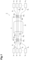
- FIG. 1 is a diagram illustrating an example of a configuration of an optical communication system to which an optical fiber cable according to the embodiment of the present disclosure is applicable.
- An optical communication system 1 illustrated in Fig. 1 includes an optical cable 2 as a transmission medium, n optical transceivers 3 1 , 3 2 , 3 3 ,..., and 3 n arranged on one end portion side of the optical cable 2, and n optical transceivers 4 1 , 4 2 , 4 3 ..., and 4 n arranged on the other end portion side of the optical cable 2.
- n is an integer of 2 or more and 100,000 or less, and a lower limit condition of the integer "n” may be preferably 10 or more, 100 or more, or 1000 or more.
- connection optical wirings (optical fibers) 5 1 , 5 2 , 5 3 ,..., and 5 n extend from the n optical transceivers 3 1 , 3 2 , 3 3 ,..., and 3 n , respectively
- n connection optical wirings (optical fibers) 6 1 , 6 2 , 6 3 ,..., and 6 n extend from the n optical transceivers 4 1 , 4 2 , 4 3 ..., and 4 n , respectively.
- the optical cable 2 includes n optical fibers 22 1 , 22 2 , 22 3 ,..., and 22 n and a sheath 21 that houses the n optical fibers.
- the n optical fibers 22 1 , 22 2 , 22 3 ,..., and 22 n may be divided into a plurality of groups, each of the optical fiber groups may be individually ribbonized, and then the plurality of ribbons obtained may be unitized.
- n optical fibers 22 1 , 22 2 , 22 3 ,..., and 22 n are connected to the n connection optical wirings 5 1 , 5 2 , 5 3 ,..., and 5 n extending from the n optical transceivers 3 1 , 3 2 , 3 3 ,..., and 3 n via n optical connectors 23 1 , 23 2 , 23 3 ,..., and 23 n , respectively.
- n optical fibers 22 1 , 22 2 , 22 3 ,..., and 22 n are connected to the n connection optical wirings 6 1 , 6 2 , 6 3 ,..., and 6 n extending from the n optical transceivers 4 1 , 4 2 , 4 3 ..., and 4 n via n optical connectors 24 1 , 24 2 , 24 3 ,..., and 24 n , respectively.
- a single core connector structure that realizes optical connection of one optical fiber by one optical connector is illustrated, a multi-core connector structure that realizes optical connection of a plurality of optical fibers by one optical connector may be adopted.
- a cable cutoff wavelength of an LP02 mode is 1060 nm or less, preferably 980 nm or less, and more preferably 850 nm or less.
- a cable cutoff wavelength of an LP11 mode is 1260 nm or less.
- a bending loss at a diameter of 15 mm is 1 dB/turn or less at a wavelength of 1625 nm.
- a mode field diameter at a wavelength of 1310 nm is 8.2 ⁇ m or more and 9.6 ⁇ m or less.
- optical transmission by the optical transceiver in the wavelength band of 1260 nm or more and 1625 nm or less can be performed, but also optical transmission using an optical transceiver for a short wavelength band (wavelength range of 850 nm or more and 1060 nm or less) such as a wavelength band of 850 nm, a wavelength band of 980 nm, and a wavelength band of 1060 nm can be performed by managing mode coupling due to axial deviation and angular deviation at a connection portion (optical connector) to be low.
- a price-to-performance ratio of the optical communication system can be optimized by using an optical transceiver of an optimal wavelength band at each time without rewiring the optical cable.
- mode dispersion is also optimized in each of the n optical fibers 22 1 , 22 2 , 22 3 ,..., and 22 n or in each of at least two of these optical fibers. Specifically, at a wavelength of 1060 nm, a wavelength of 980 nm, or a wavelength of 850 nm, the mode dispersion between the LP01 mode and the LP11 mode is 1000 ps/km or less, preferably 300 ps/km or less.
- the transmission performance of the optical communication system 1 can be improved or the connection cost can be reduced.
- all the n optical fibers 22 1 , 22 2 , 22 3 ,..., and 22 n included in the optical cable 2 satisfy the above-described optical characteristics regarding the optical fiber.
- all optical fibers included in a target unit or a target ribbon may be configured to satisfy the optical characteristics for each unit constituting the optical cable 2 or each ribbon (one unit to be handled as the optical fiber group) constituting each unit, and thus, the price-to-performance ratio can be optimized.
- the structure illustrated in Fig. 2 need not be applied to all of the n optical fibers 22 1 , 22 2 , 22 3 ,..., and 22 n housed in the sheath 21 of the optical cable 2, and may be applied to at least two optical fibers.
- the optical fiber 22 k includes a core 61 extending along a fiber axis (central axis) AX, a cladding 62 provided on an outer peripheral surface of the core 61, a first coating 63 provided on an outer peripheral surface of the cladding 62, and a second coating 64.
- the first coating 63 and the second coating 64 constitute a resin coating provided on the outer peripheral surface of the cladding 62.
- the cladding 62 includes an inner cladding 62a provided on the outer peripheral surface of the core and an outer cladding 62b provided on an outer peripheral surface of the inner cladding 62a.
- the core 61 and the cladding 62 are comprised of silica glass, and may contain dopant for adjusting a refractive index of Ge, F, Cl, Br, or P.
- the inner cladding 62a has a refractive index lower than a refractive index of the core 61.
- the optical fiber has a single guided mode at a wavelength of 1260 nm (single mode operation can be performed).
- An outer diameter of the cladding 62 is preferably a standard outer diameter (glass outer diameter) of 124 ⁇ m or more and 126 ⁇ m or less.
- the optical fiber 22 k can cope with high-speed transmission in a short wavelength band of 850 nm or more and 1060 nm or less and can also cope with high spatial density and high-speed transmission at a wavelength of 1625 nm.
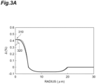
- Fig. 3A illustrates refractive index profiles of an example of the optical fiber according to the embodiment of the present disclosure and an optical fiber according to a comparative example.
- reference sign 310 denotes a refractive index profile of an optical fiber 22 k according to the embodiment of the present disclosure
- reference sign 320 denotes a refractive index profile of the optical fiber according to the comparative example.
- an exponent ⁇ in the above Formula (2) is adjusted, and thus, as described above, the mode field diameter at a wavelength of 1310 nm is 8.2 ⁇ m or more and 9.6 ⁇ m or less, the cable cutoff wavelength of the LP11 mode is 1060 nm or more and 1260 nm or less, and the cable cutoff wavelength of the LP02 mode is 1060 nm or less.
- a ratio of (radius of core 61)/(outer radius of inner cladding 62a) is 0.25 ⁇ 0.02.
- the outer cladding 62b is comprised of pure silica glass and has an outer radius (cladding outer diameter) of 62.5 ⁇ m ⁇ 0.5 ⁇ m.
- the optical fiber according to the comparative example has a structure similar to the above-described optical fiber 22 k except for the profile shape of the inner region of the core 61. That is, in the inner region of the core, the refractive index profile 320 has a shape corresponding to the above Formula (2) (the relative refractive index difference at the core center is ⁇ 0, the relative refractive index difference at the outer peripheral portion of the inner region is ⁇ 1, and the index ⁇ is 3.4), and the relative refractive index difference ⁇ 0 at the core center decreases to 0.8 ⁇ 0.1 times the maximum relative refractive index difference. Such a depression of the refractive index at the core center may occur due to the influence of a core manufacturing technology.
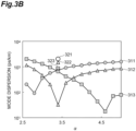
- Fig. 3B is a graph representing a relationship between the exponent ⁇ and the mode dispersion for each of a plurality of samples and a plurality of comparative examples of the optical fiber 22 k (the optical fiber according to the embodiment of the present disclosure) having the above-described structure. Specifically, the graph represented in Fig. 3B shows changes in the mode dispersion of the samples and the comparative examples when the exponent ⁇ in the above Formula (2) is changed within a range of 2.6 or more and 5.0 or less.
- a graph 311 represents a measurement result (a relationship between the exponent ⁇ and the mode dispersion) of a first sample of the optical fiber 22 k in which the cable cutoff wavelength of the LP02 mode is set to 850 nm
- a graph 312 represents a measurement result of a second sample of the optical fiber 22 k in which the cable cutoff wavelength of the LP02 mode is set to 980 nm
- a graph 313 represents a measurement result of a third sample of the optical fiber 22 k in which the cable cutoff wavelength of the LP02 mode is set to 1060 nm.
- a point 321 indicates a measurement result (a relationship between the exponent ⁇ and the mode dispersion) of a first comparative example in which the cable cutoff wavelength of the LP02 mode is set to 850 nm
- a point 322 indicates a measurement result of a second comparative example in which the cable cutoff wavelength of the LP02 mode is set to 980 nm
- a point 323 indicates a measurement result of a third comparative example in which the cable cutoff wavelength of the LP02 mode is set to 1060 nm.
- all of the first sample, the second sample, and the third sample of the optical fiber 22 k are suitable for high-speed transmission since the mode dispersion can be suppressed to 300 ps/km or less at an optimum value of the exponent ⁇ .
- the optimum value of the exponent ⁇ in the first sample is around 2.8 ⁇ 0.1
- the optimum value of the exponent ⁇ in the second sample is around 3.4 ⁇ 0.1
- the optimum value of the exponent ⁇ in the third sample is around 4.6 ⁇ 0.1.
- the value of the exponent ⁇ is set to 3.4 ⁇ 0.1 (range of 3.3 or more and 3.5 or less), and thus, the mode dispersion can be suppressed to 1000 ps/km or less in all the wavelength bands of the wavelength band of 850 nm, the wavelength band of 980 nm, and the wavelength band of 1060 nm (wavelength range of 850 nm or more and 1060 nm or less).
- each of the graphs 311, 312, and 313 has a lower mode dispersion than the points 321, 322, and 323. This represents an effect of reducing the depression of the refractive index at the center of the core.
- a value 3 ⁇ defined by a standard deviation ⁇ of variations in the outer diameter (the outer diameter of the glass portion) of the cladding 62 (variations in an outer diameter along a longitudinal direction coinciding with the fiber axis AX) is preferably 0.1 ⁇ m or more and 0.5 ⁇ m or less.
- the value 3 ⁇ is more preferably 0.2 ⁇ m or more and 0.5 ⁇ m or less.
Landscapes
- Physics & Mathematics (AREA)
- General Physics & Mathematics (AREA)
- Optics & Photonics (AREA)
- Chemical & Material Sciences (AREA)
- Dispersion Chemistry (AREA)
- Crystallography & Structural Chemistry (AREA)
- Optical Fibers, Optical Fiber Cores, And Optical Fiber Bundles (AREA)
- Optical Communication System (AREA)
Applications Claiming Priority (2)
| Application Number | Priority Date | Filing Date | Title |
|---|---|---|---|
| JP2019193666 | 2019-10-24 | ||
| PCT/JP2020/038650 WO2021079788A1 (ja) | 2019-10-24 | 2020-10-13 | 光ファイバおよび光ケーブル |
Publications (3)
| Publication Number | Publication Date |
|---|---|
| EP4050388A1 EP4050388A1 (en) | 2022-08-31 |
| EP4050388A4 EP4050388A4 (en) | 2022-11-16 |
| EP4050388B1 true EP4050388B1 (en) | 2025-04-09 |
Family
ID=75619410
Family Applications (1)
| Application Number | Title | Priority Date | Filing Date |
|---|---|---|---|
| EP20878082.5A Active EP4050388B1 (en) | 2019-10-24 | 2020-10-13 | Optical fiber and optical cable |
Country Status (5)
| Country | Link |
|---|---|
| US (1) | US11841529B2 (https=) |
| EP (1) | EP4050388B1 (https=) |
| JP (1) | JPWO2021079788A1 (https=) |
| CN (1) | CN114556171B (https=) |
| WO (1) | WO2021079788A1 (https=) |
Families Citing this family (1)
| Publication number | Priority date | Publication date | Assignee | Title |
|---|---|---|---|---|
| CN114415299B (zh) * | 2022-03-30 | 2022-06-24 | 深圳市埃尔法光电科技有限公司 | 一种光纤信号直导式光模块 |
Family Cites Families (14)
| Publication number | Priority date | Publication date | Assignee | Title |
|---|---|---|---|---|
| US7187833B2 (en) * | 2004-04-29 | 2007-03-06 | Corning Incorporated | Low attenuation large effective area optical fiber |
| US7336877B2 (en) | 2004-08-31 | 2008-02-26 | Corning Incorporated | Broadband optical fiber |
| US7406237B2 (en) * | 2006-02-21 | 2008-07-29 | Corning Incorporated | Multiband optical fiber |
| US7620282B2 (en) * | 2006-08-31 | 2009-11-17 | Corning Incorporated | Low bend loss single mode optical fiber |
| US7450807B2 (en) * | 2006-08-31 | 2008-11-11 | Corning Incorporated | Low bend loss optical fiber with deep depressed ring |
| DK2581770T3 (da) * | 2008-02-22 | 2014-06-30 | Sumitomo Electric Industries | Optisk fiber og optisk kabel |
| JP2012212115A (ja) * | 2011-03-23 | 2012-11-01 | Sumitomo Electric Ind Ltd | 光ファイバ、光ファイバコードおよび光ファイバケーブル |
| WO2015182159A1 (ja) | 2014-05-30 | 2015-12-03 | 株式会社クラレ | 培養方法及び細胞塊 |
| JP7049252B2 (ja) * | 2015-09-15 | 2022-04-06 | コーニング インコーポレイテッド | 塩素でアップドーピングされたクラッドを有する低曲げ損失シングルモード光ファイバ |
| US9995873B2 (en) | 2016-07-29 | 2018-06-12 | Corning Incorporated | Single-mode large effective area optical fibers |
| JP6911307B2 (ja) | 2016-09-13 | 2021-07-28 | 住友電気工業株式会社 | 光ファイバおよび光ファイバ心線 |
| PL3729151T3 (pl) * | 2017-12-21 | 2022-07-25 | Draka Comteq France | Niewrażliwy na zginanie światłowód jednomodowy z płytkim rowkiem oraz odpowiedni system optyczny |
| JP2019120894A (ja) * | 2018-01-11 | 2019-07-22 | 住友電気工業株式会社 | 光ファイバ、光ファイバ心線および光伝送システム |
| JP2019152811A (ja) * | 2018-03-06 | 2019-09-12 | 住友電気工業株式会社 | 光ファイバ、光ファイバ心線および光伝送システム |
-
2020
- 2020-10-13 JP JP2021554309A patent/JPWO2021079788A1/ja active Pending
- 2020-10-13 EP EP20878082.5A patent/EP4050388B1/en active Active
- 2020-10-13 US US17/754,682 patent/US11841529B2/en active Active
- 2020-10-13 WO PCT/JP2020/038650 patent/WO2021079788A1/ja not_active Ceased
- 2020-10-13 CN CN202080071303.6A patent/CN114556171B/zh active Active
Also Published As
| Publication number | Publication date |
|---|---|
| WO2021079788A1 (ja) | 2021-04-29 |
| CN114556171A (zh) | 2022-05-27 |
| EP4050388A4 (en) | 2022-11-16 |
| JPWO2021079788A1 (https=) | 2021-04-29 |
| EP4050388A1 (en) | 2022-08-31 |
| CN114556171B (zh) | 2025-07-01 |
| US20230228936A1 (en) | 2023-07-20 |
| US11841529B2 (en) | 2023-12-12 |
Similar Documents
| Publication | Publication Date | Title |
|---|---|---|
| JP6361101B2 (ja) | 光ファイバ | |
| DK1930753T3 (en) | Optical fiber having a high Brillouin threshold strength and low bending | |
| US8737793B2 (en) | Multi-core optical fiber and method of manufacturing the same | |
| EP1978383B1 (en) | Transmission optical fiber having large effective area | |
| EP3399357B1 (en) | Non-zero dispersion shifted optical fiber having a short cutoff wavelength | |
| US20120134637A1 (en) | Multi-core optical fiber and method of manufacturing the same | |
| US8705922B2 (en) | Few-moded optical fibers | |
| JP2020098350A (ja) | 光コネクタ | |
| US8315494B2 (en) | Optical fiber | |
| JP4192425B2 (ja) | 光ファイバ | |
| JPWO2000031573A1 (ja) | 光ファイバ及びそれを含む光伝送システム | |
| CN112219145A (zh) | 多芯光纤和多芯光纤缆线 | |
| WO2020013297A1 (ja) | 光ファイバ | |
| JP2005516255A (ja) | 高次モード除去光ファイバ、モジュール及びこれらを用いたシステム | |
| CN110418990B (zh) | 空分复用所用的弱耦合少模光纤 | |
| EP4050388B1 (en) | Optical fiber and optical cable | |
| US20230305221A1 (en) | Optical fibers for single mode and few mode vcsel-based optical fiber transmission systems | |
| JP4861181B2 (ja) | 標準的なシングルモードファイバに対する、高性能指数の分散補償ファイバおよび当該分散補償ファイバを使用する伝送システム | |
| WO2024257700A1 (ja) | マルチコアファイバ | |
| JP4690249B2 (ja) | 高屈曲性光ファイバ | |
| WO2016129367A1 (ja) | 分散シフト光ファイバ | |
| JP4079045B2 (ja) | 光ファイバ、分散補償モジュール及び光伝送システム | |
| WO2025143138A1 (ja) | 光ファイバ | |
| WO2024150692A1 (ja) | 光ファイバ | |
| JP2004021075A (ja) | 分散補償光ファイバおよびそれを用いた光伝送路 |
Legal Events
| Date | Code | Title | Description |
|---|---|---|---|
| STAA | Information on the status of an ep patent application or granted ep patent |
Free format text: STATUS: THE INTERNATIONAL PUBLICATION HAS BEEN MADE |
|
| PUAI | Public reference made under article 153(3) epc to a published international application that has entered the european phase |
Free format text: ORIGINAL CODE: 0009012 |
|
| STAA | Information on the status of an ep patent application or granted ep patent |
Free format text: STATUS: REQUEST FOR EXAMINATION WAS MADE |
|
| 17P | Request for examination filed |
Effective date: 20220331 |
|
| AK | Designated contracting states |
Kind code of ref document: A1 Designated state(s): AL AT BE BG CH CY CZ DE DK EE ES FI FR GB GR HR HU IE IS IT LI LT LU LV MC MK MT NL NO PL PT RO RS SE SI SK SM TR |
|
| A4 | Supplementary search report drawn up and despatched |
Effective date: 20221014 |
|
| RIC1 | Information provided on ipc code assigned before grant |
Ipc: G02B 6/02 20060101ALI20221010BHEP Ipc: G02B 6/036 20060101ALI20221010BHEP Ipc: G02B 6/028 20060101AFI20221010BHEP |
|
| DAV | Request for validation of the european patent (deleted) | ||
| DAX | Request for extension of the european patent (deleted) | ||
| GRAP | Despatch of communication of intention to grant a patent |
Free format text: ORIGINAL CODE: EPIDOSNIGR1 |
|
| STAA | Information on the status of an ep patent application or granted ep patent |
Free format text: STATUS: GRANT OF PATENT IS INTENDED |
|
| INTG | Intention to grant announced |
Effective date: 20241118 |
|
| P01 | Opt-out of the competence of the unified patent court (upc) registered |
Free format text: CASE NUMBER: APP_3443/2025 Effective date: 20250122 |
|
| GRAS | Grant fee paid |
Free format text: ORIGINAL CODE: EPIDOSNIGR3 |
|
| GRAA | (expected) grant |
Free format text: ORIGINAL CODE: 0009210 |
|
| STAA | Information on the status of an ep patent application or granted ep patent |
Free format text: STATUS: THE PATENT HAS BEEN GRANTED |
|
| AK | Designated contracting states |
Kind code of ref document: B1 Designated state(s): AL AT BE BG CH CY CZ DE DK EE ES FI FR GB GR HR HU IE IS IT LI LT LU LV MC MK MT NL NO PL PT RO RS SE SI SK SM TR |
|
| REG | Reference to a national code |
Ref country code: GB Ref legal event code: FG4D |
|
| REG | Reference to a national code |
Ref country code: CH Ref legal event code: EP |
|
| REG | Reference to a national code |
Ref country code: DE Ref legal event code: R096 Ref document number: 602020049299 Country of ref document: DE |
|
| REG | Reference to a national code |
Ref country code: IE Ref legal event code: FG4D |
|
| REG | Reference to a national code |
Ref country code: NL Ref legal event code: MP Effective date: 20250409 |
|
| PG25 | Lapsed in a contracting state [announced via postgrant information from national office to epo] |
Ref country code: NL Free format text: LAPSE BECAUSE OF FAILURE TO SUBMIT A TRANSLATION OF THE DESCRIPTION OR TO PAY THE FEE WITHIN THE PRESCRIBED TIME-LIMIT Effective date: 20250409 |
|
| REG | Reference to a national code |
Ref country code: AT Ref legal event code: MK05 Ref document number: 1784012 Country of ref document: AT Kind code of ref document: T Effective date: 20250409 |
|
| PG25 | Lapsed in a contracting state [announced via postgrant information from national office to epo] |
Ref country code: PT Free format text: LAPSE BECAUSE OF FAILURE TO SUBMIT A TRANSLATION OF THE DESCRIPTION OR TO PAY THE FEE WITHIN THE PRESCRIBED TIME-LIMIT Effective date: 20250811 Ref country code: FI Free format text: LAPSE BECAUSE OF FAILURE TO SUBMIT A TRANSLATION OF THE DESCRIPTION OR TO PAY THE FEE WITHIN THE PRESCRIBED TIME-LIMIT Effective date: 20250409 Ref country code: ES Free format text: LAPSE BECAUSE OF FAILURE TO SUBMIT A TRANSLATION OF THE DESCRIPTION OR TO PAY THE FEE WITHIN THE PRESCRIBED TIME-LIMIT Effective date: 20250409 |
|
| REG | Reference to a national code |
Ref country code: LT Ref legal event code: MG9D |
|
| PG25 | Lapsed in a contracting state [announced via postgrant information from national office to epo] |
Ref country code: GR Free format text: LAPSE BECAUSE OF FAILURE TO SUBMIT A TRANSLATION OF THE DESCRIPTION OR TO PAY THE FEE WITHIN THE PRESCRIBED TIME-LIMIT Effective date: 20250710 Ref country code: NO Free format text: LAPSE BECAUSE OF FAILURE TO SUBMIT A TRANSLATION OF THE DESCRIPTION OR TO PAY THE FEE WITHIN THE PRESCRIBED TIME-LIMIT Effective date: 20250709 |
|
| PG25 | Lapsed in a contracting state [announced via postgrant information from national office to epo] |
Ref country code: PL Free format text: LAPSE BECAUSE OF FAILURE TO SUBMIT A TRANSLATION OF THE DESCRIPTION OR TO PAY THE FEE WITHIN THE PRESCRIBED TIME-LIMIT Effective date: 20250409 |
|
| PG25 | Lapsed in a contracting state [announced via postgrant information from national office to epo] |
Ref country code: BG Free format text: LAPSE BECAUSE OF FAILURE TO SUBMIT A TRANSLATION OF THE DESCRIPTION OR TO PAY THE FEE WITHIN THE PRESCRIBED TIME-LIMIT Effective date: 20250409 |
|
| PG25 | Lapsed in a contracting state [announced via postgrant information from national office to epo] |
Ref country code: HR Free format text: LAPSE BECAUSE OF FAILURE TO SUBMIT A TRANSLATION OF THE DESCRIPTION OR TO PAY THE FEE WITHIN THE PRESCRIBED TIME-LIMIT Effective date: 20250409 |
|
| PG25 | Lapsed in a contracting state [announced via postgrant information from national office to epo] |
Ref country code: AT Free format text: LAPSE BECAUSE OF FAILURE TO SUBMIT A TRANSLATION OF THE DESCRIPTION OR TO PAY THE FEE WITHIN THE PRESCRIBED TIME-LIMIT Effective date: 20250409 |
|
| PGFP | Annual fee paid to national office [announced via postgrant information from national office to epo] |
Ref country code: FR Payment date: 20250908 Year of fee payment: 6 |
|
| PG25 | Lapsed in a contracting state [announced via postgrant information from national office to epo] |
Ref country code: RS Free format text: LAPSE BECAUSE OF FAILURE TO SUBMIT A TRANSLATION OF THE DESCRIPTION OR TO PAY THE FEE WITHIN THE PRESCRIBED TIME-LIMIT Effective date: 20250709 |
|
| PG25 | Lapsed in a contracting state [announced via postgrant information from national office to epo] |
Ref country code: IS Free format text: LAPSE BECAUSE OF FAILURE TO SUBMIT A TRANSLATION OF THE DESCRIPTION OR TO PAY THE FEE WITHIN THE PRESCRIBED TIME-LIMIT Effective date: 20250809 |
|
| PG25 | Lapsed in a contracting state [announced via postgrant information from national office to epo] |
Ref country code: LV Free format text: LAPSE BECAUSE OF FAILURE TO SUBMIT A TRANSLATION OF THE DESCRIPTION OR TO PAY THE FEE WITHIN THE PRESCRIBED TIME-LIMIT Effective date: 20250409 |
|
| REG | Reference to a national code |
Ref country code: DE Ref legal event code: R097 Ref document number: 602020049299 Country of ref document: DE |
|
| PG25 | Lapsed in a contracting state [announced via postgrant information from national office to epo] |
Ref country code: SM Free format text: LAPSE BECAUSE OF FAILURE TO SUBMIT A TRANSLATION OF THE DESCRIPTION OR TO PAY THE FEE WITHIN THE PRESCRIBED TIME-LIMIT Effective date: 20250409 Ref country code: DK Free format text: LAPSE BECAUSE OF FAILURE TO SUBMIT A TRANSLATION OF THE DESCRIPTION OR TO PAY THE FEE WITHIN THE PRESCRIBED TIME-LIMIT Effective date: 20250409 |
|
| PG25 | Lapsed in a contracting state [announced via postgrant information from national office to epo] |
Ref country code: CZ Free format text: LAPSE BECAUSE OF FAILURE TO SUBMIT A TRANSLATION OF THE DESCRIPTION OR TO PAY THE FEE WITHIN THE PRESCRIBED TIME-LIMIT Effective date: 20250409 |
|
| PG25 | Lapsed in a contracting state [announced via postgrant information from national office to epo] |
Ref country code: EE Free format text: LAPSE BECAUSE OF FAILURE TO SUBMIT A TRANSLATION OF THE DESCRIPTION OR TO PAY THE FEE WITHIN THE PRESCRIBED TIME-LIMIT Effective date: 20250409 |
|
| PG25 | Lapsed in a contracting state [announced via postgrant information from national office to epo] |
Ref country code: SK Free format text: LAPSE BECAUSE OF FAILURE TO SUBMIT A TRANSLATION OF THE DESCRIPTION OR TO PAY THE FEE WITHIN THE PRESCRIBED TIME-LIMIT Effective date: 20250409 |
|
| PG25 | Lapsed in a contracting state [announced via postgrant information from national office to epo] |
Ref country code: IT Free format text: LAPSE BECAUSE OF FAILURE TO SUBMIT A TRANSLATION OF THE DESCRIPTION OR TO PAY THE FEE WITHIN THE PRESCRIBED TIME-LIMIT Effective date: 20250409 |
|
| PG25 | Lapsed in a contracting state [announced via postgrant information from national office to epo] |
Ref country code: RO Free format text: LAPSE BECAUSE OF FAILURE TO SUBMIT A TRANSLATION OF THE DESCRIPTION OR TO PAY THE FEE WITHIN THE PRESCRIBED TIME-LIMIT Effective date: 20250409 |
|
| PLBE | No opposition filed within time limit |
Free format text: ORIGINAL CODE: 0009261 |
|
| STAA | Information on the status of an ep patent application or granted ep patent |
Free format text: STATUS: NO OPPOSITION FILED WITHIN TIME LIMIT |
|
| REG | Reference to a national code |
Ref country code: CH Ref legal event code: L10 Free format text: ST27 STATUS EVENT CODE: U-0-0-L10-L00 (AS PROVIDED BY THE NATIONAL OFFICE) Effective date: 20260218 |
|
| 26N | No opposition filed |
Effective date: 20260112 |