EP4049934B1 - Luftfahrzeug, das einen motor und ein kühlsystem auf wasserstoffbasis umfasst - Google Patents
Luftfahrzeug, das einen motor und ein kühlsystem auf wasserstoffbasis umfasst Download PDFInfo
- Publication number
- EP4049934B1 EP4049934B1 EP22157746.3A EP22157746A EP4049934B1 EP 4049934 B1 EP4049934 B1 EP 4049934B1 EP 22157746 A EP22157746 A EP 22157746A EP 4049934 B1 EP4049934 B1 EP 4049934B1
- Authority
- EP
- European Patent Office
- Prior art keywords
- heat exchanger
- aircraft
- air
- fuel
- engine
- Prior art date
- Legal status (The legal status is an assumption and is not a legal conclusion. Google has not performed a legal analysis and makes no representation as to the accuracy of the status listed.)
- Active
Links
Images


Classifications
-
- B—PERFORMING OPERATIONS; TRANSPORTING
- B64—AIRCRAFT; AVIATION; COSMONAUTICS
- B64D—EQUIPMENT FOR FITTING IN OR TO AIRCRAFT; FLIGHT SUITS; PARACHUTES; ARRANGEMENT OR MOUNTING OF POWER PLANTS OR PROPULSION TRANSMISSIONS IN AIRCRAFT
- B64D37/00—Arrangements in connection with fuel supply for power plant
-
- F—MECHANICAL ENGINEERING; LIGHTING; HEATING; WEAPONS; BLASTING
- F02—COMBUSTION ENGINES; HOT-GAS OR COMBUSTION-PRODUCT ENGINE PLANTS
- F02C—GAS-TURBINE PLANTS; AIR INTAKES FOR JET-PROPULSION PLANTS; CONTROLLING FUEL SUPPLY IN AIR-BREATHING JET-PROPULSION PLANTS
- F02C3/00—Gas-turbine plants characterised by the use of combustion products as the working fluid
- F02C3/20—Gas-turbine plants characterised by the use of combustion products as the working fluid using a special fuel, oxidant, or dilution fluid to generate the combustion products
- F02C3/22—Gas-turbine plants characterised by the use of combustion products as the working fluid using a special fuel, oxidant, or dilution fluid to generate the combustion products the fuel or oxidant being gaseous at standard temperature and pressure
-
- B—PERFORMING OPERATIONS; TRANSPORTING
- B64—AIRCRAFT; AVIATION; COSMONAUTICS
- B64D—EQUIPMENT FOR FITTING IN OR TO AIRCRAFT; FLIGHT SUITS; PARACHUTES; ARRANGEMENT OR MOUNTING OF POWER PLANTS OR PROPULSION TRANSMISSIONS IN AIRCRAFT
- B64D37/00—Arrangements in connection with fuel supply for power plant
- B64D37/34—Conditioning fuel, e.g. heating
-
- B—PERFORMING OPERATIONS; TRANSPORTING
- B64—AIRCRAFT; AVIATION; COSMONAUTICS
- B64D—EQUIPMENT FOR FITTING IN OR TO AIRCRAFT; FLIGHT SUITS; PARACHUTES; ARRANGEMENT OR MOUNTING OF POWER PLANTS OR PROPULSION TRANSMISSIONS IN AIRCRAFT
- B64D15/00—De-icing or preventing icing on exterior surfaces of aircraft
- B64D15/02—De-icing or preventing icing on exterior surfaces of aircraft by ducted hot gas or liquid
- B64D15/04—Hot gas application
-
- B—PERFORMING OPERATIONS; TRANSPORTING
- B64—AIRCRAFT; AVIATION; COSMONAUTICS
- B64D—EQUIPMENT FOR FITTING IN OR TO AIRCRAFT; FLIGHT SUITS; PARACHUTES; ARRANGEMENT OR MOUNTING OF POWER PLANTS OR PROPULSION TRANSMISSIONS IN AIRCRAFT
- B64D27/00—Arrangement or mounting of power plants in aircraft; Aircraft characterised by the type or position of power plants
- B64D27/02—Aircraft characterised by the type or position of power plants
- B64D27/16—Aircraft characterised by the type or position of power plants of jet type
-
- B—PERFORMING OPERATIONS; TRANSPORTING
- B64—AIRCRAFT; AVIATION; COSMONAUTICS
- B64D—EQUIPMENT FOR FITTING IN OR TO AIRCRAFT; FLIGHT SUITS; PARACHUTES; ARRANGEMENT OR MOUNTING OF POWER PLANTS OR PROPULSION TRANSMISSIONS IN AIRCRAFT
- B64D33/00—Arrangement in aircraft of power plant parts or auxiliaries not otherwise provided for
- B64D33/08—Arrangement in aircraft of power plant parts or auxiliaries not otherwise provided for of power plant cooling systems
-
- F—MECHANICAL ENGINEERING; LIGHTING; HEATING; WEAPONS; BLASTING
- F02—COMBUSTION ENGINES; HOT-GAS OR COMBUSTION-PRODUCT ENGINE PLANTS
- F02C—GAS-TURBINE PLANTS; AIR INTAKES FOR JET-PROPULSION PLANTS; CONTROLLING FUEL SUPPLY IN AIR-BREATHING JET-PROPULSION PLANTS
- F02C7/00—Features, components parts, details or accessories, not provided for in, or of interest apart form groups F02C1/00 - F02C6/00; Air intakes for jet-propulsion plants
- F02C7/12—Cooling of plants
- F02C7/14—Cooling of plants of fluids in the plant, e.g. lubricant or fuel
-
- F—MECHANICAL ENGINEERING; LIGHTING; HEATING; WEAPONS; BLASTING
- F02—COMBUSTION ENGINES; HOT-GAS OR COMBUSTION-PRODUCT ENGINE PLANTS
- F02C—GAS-TURBINE PLANTS; AIR INTAKES FOR JET-PROPULSION PLANTS; CONTROLLING FUEL SUPPLY IN AIR-BREATHING JET-PROPULSION PLANTS
- F02C7/00—Features, components parts, details or accessories, not provided for in, or of interest apart form groups F02C1/00 - F02C6/00; Air intakes for jet-propulsion plants
- F02C7/12—Cooling of plants
- F02C7/16—Cooling of plants characterised by cooling medium
-
- F—MECHANICAL ENGINEERING; LIGHTING; HEATING; WEAPONS; BLASTING
- F02—COMBUSTION ENGINES; HOT-GAS OR COMBUSTION-PRODUCT ENGINE PLANTS
- F02C—GAS-TURBINE PLANTS; AIR INTAKES FOR JET-PROPULSION PLANTS; CONTROLLING FUEL SUPPLY IN AIR-BREATHING JET-PROPULSION PLANTS
- F02C7/00—Features, components parts, details or accessories, not provided for in, or of interest apart form groups F02C1/00 - F02C6/00; Air intakes for jet-propulsion plants
- F02C7/22—Fuel supply systems
- F02C7/224—Heating fuel before feeding to the burner
-
- F—MECHANICAL ENGINEERING; LIGHTING; HEATING; WEAPONS; BLASTING
- F05—INDEXING SCHEMES RELATING TO ENGINES OR PUMPS IN VARIOUS SUBCLASSES OF CLASSES F01-F04
- F05D—INDEXING SCHEME FOR ASPECTS RELATING TO NON-POSITIVE-DISPLACEMENT MACHINES OR ENGINES, GAS-TURBINES OR JET-PROPULSION PLANTS
- F05D2220/00—Application
- F05D2220/30—Application in turbines
- F05D2220/32—Application in turbines in gas turbines
- F05D2220/323—Application in turbines in gas turbines for aircraft propulsion, e.g. jet engines
-
- F—MECHANICAL ENGINEERING; LIGHTING; HEATING; WEAPONS; BLASTING
- F05—INDEXING SCHEMES RELATING TO ENGINES OR PUMPS IN VARIOUS SUBCLASSES OF CLASSES F01-F04
- F05D—INDEXING SCHEME FOR ASPECTS RELATING TO NON-POSITIVE-DISPLACEMENT MACHINES OR ENGINES, GAS-TURBINES OR JET-PROPULSION PLANTS
- F05D2260/00—Function
- F05D2260/20—Heat transfer, e.g. cooling
- F05D2260/205—Cooling fluid recirculation, i.e. after cooling one or more components is the cooling fluid recovered and used elsewhere for other purposes
-
- F—MECHANICAL ENGINEERING; LIGHTING; HEATING; WEAPONS; BLASTING
- F05—INDEXING SCHEMES RELATING TO ENGINES OR PUMPS IN VARIOUS SUBCLASSES OF CLASSES F01-F04
- F05D—INDEXING SCHEME FOR ASPECTS RELATING TO NON-POSITIVE-DISPLACEMENT MACHINES OR ENGINES, GAS-TURBINES OR JET-PROPULSION PLANTS
- F05D2260/00—Function
- F05D2260/20—Heat transfer, e.g. cooling
- F05D2260/213—Heat transfer, e.g. cooling by the provision of a heat exchanger within the cooling circuit
-
- F—MECHANICAL ENGINEERING; LIGHTING; HEATING; WEAPONS; BLASTING
- F05—INDEXING SCHEMES RELATING TO ENGINES OR PUMPS IN VARIOUS SUBCLASSES OF CLASSES F01-F04
- F05D—INDEXING SCHEME FOR ASPECTS RELATING TO NON-POSITIVE-DISPLACEMENT MACHINES OR ENGINES, GAS-TURBINES OR JET-PROPULSION PLANTS
- F05D2260/00—Function
- F05D2260/98—Lubrication
Definitions
- the present invention relates to an aircraft comprising an engine and a dihydrogen-based cooling system.
- An aircraft conventionally comprises a fuselage which delimits a cabin for passengers and cabin crew.
- the term “cabin” includes not only the cabin in which passengers sit, but also the cockpit.
- the aircraft also includes de-icing means, for example to de-ice the wings.
- the cabin and the defrosting means constitute devices to be heated.
- the aircraft also includes at least one turbojet engine which drives the aircraft and which is supplied with kerosene from a tank.
- the aircraft also includes an air conditioning system which takes hot air from the turbojet, which regulates the temperature of the air thus taken and which sends the air thus regulated to the devices to be heated, including the cabin. to regulate the temperature and the means of defrosting.
- an air conditioning system which takes hot air from the turbojet, which regulates the temperature of the air thus taken and which sends the air thus regulated to the devices to be heated, including the cabin. to regulate the temperature and the means of defrosting.
- the conditioning system thus includes heat exchangers, filters, pipes, valves, etc., and it captures the hot air from the turbojet to treat it and return it to its destination, in particular, to the devices to be heated. .
- FIG. 5 is a schematic representation of such an aircraft 500 of the state of the art.
- the aircraft 500 comprises a turbojet 501 which incorporates, among other things, a transmission box and which also comprises a fan arranged in a fan channel and intended to generate a flow of air in the turbojet 501 in a direction of movement of the air in the turbojet 501, where in a known manner, the air flow then moves downstream of the fan in a primary stream or in a secondary stream of the turbojet 501.
- the turbojet 501 also comprises an engine compressor which comprises a low pressure compressor downstream of the fan and a high pressure compressor downstream of the low pressure compressor, and an engine turbine which comprises a high pressure turbine downstream of the high pressure compressor, and a low pressure turbine downstream of the high pressure turbine.
- the air pushed by the fan and passing through the primary stream passes successively through the low pressure compressor, the high pressure compressor, the high pressure turbine, and the low pressure turbine, to be ejected towards the outside. Between the high pressure compressor and the high pressure turbine, the air passes through a combustion chamber where it is mixed with the fuel in order to burn the latter.
- the high pressure compressor has several compression stages where the pressure increases, from upstream to downstream depending on the direction of movement, from low pressure at the first stage, to high pressure at the last stage, in passing through intermediate pressures in the intermediate stages.
- the aircraft 500 also includes heating devices 504 (cabin, defrosting means) and an air conditioning system 506.
- the air conditioning system 506 comprises a first heat exchanger 502, a first air intake 507 intended to take, from the high pressure compressor, air at low pressure or at intermediate pressure, a second air intake 508 intended to take, from the high pressure compressor, air at high pressure.
- the air conditioning system 506 also includes a first pipe 510 which passes through the first heat exchanger 502 and supplies the devices to be heated 504 downstream of the first heat exchanger 502 relative to the direction of the air flow in the first pipe 510. Upstream of the first heat exchanger 502 relative to the direction of the air flow in the first pipe 510, the first pipe 510 is divided into two sub-pipes, one of which is fluidly connected to the first air intake 507 and the other of which is fluidly connected to the second air intake 508.
- Each sub-pipe is here equipped with a valve 512, 514 which makes it possible to regulate the passage of air coming from each air intake 507, 508 depending on the needs of the aircraft 500 and for this purpose, the aircraft 500 includes a control unit intended to control the valves 512 and 514 in opening and closing.
- the air conditioning system 506 also includes a first air pipe 516 which supplies the first heat exchanger 502 with air taken from the fan channel.
- the hot air taken from the air intakes 507 and 508 is cooled as it passes through the first heat exchanger 502 by the fresh air taken from the fan channel which is then heated and discharged to the outside. or in an engine compartment, while the cooled air is directed towards the devices to be heated 504 through the first pipe 510.
- the aircraft 500 includes a second heat exchanger 518 which is intended to carry out a heat exchange between a flow of air coming from the fan channel and a flow of oil coming from the turbojet 501.
- the aircraft 500 includes a second air pipe 520 which takes air from the fan channel to supply the second heat exchanger 518, and a first oil circuit 522 taking oil from the turbojet 501 and reinjecting this oil after passing through the second heat exchanger 518.
- the hot oil taken from the turbojet 501 is cooled as it passes through the second heat exchanger 518 by the fresh air taken from the fan channel which is then heated and discharged to the outside, while the cooled oil is directed to the turbojet 501.
- the aircraft 500 comprises a fuel tank 524 which allows kerosene to be stored and a fuel pipe 526 which supplies the combustion chamber of the turbojet 501.
- a pump 503 is arranged at the outlet of the fuel tank 524 to drive the fuel into the fuel line 526.
- the aircraft 500 includes a third heat exchanger 528 which is intended to carry out a heat exchange between the fuel coming from the fuel tank 524 and a flow of oil coming from the turbojet 501.
- the fuel line 526 takes fuel from the fuel tank 524 to supply the third heat exchanger 528, and a second oil circuit 530 takes oil from the turbojet 501 and reinjects this oil after passing through it. the third heat exchanger 528.
- the hot oil taken from the turbojet 501 is cooled as it passes through the third heat exchanger 528 by the fuel taken from the fuel tank 524 which is then heated and conveyed to the combustion chamber, while the oil cooled is directed to the turbojet 501.
- the aircraft 500 also includes an electric generator 532 which generates an electric current to power the aircraft 500.
- the aircraft 500 comprises a fourth heat exchanger 534 which is intended to carry out a heat exchange between fuel coming from the fuel tank 524 and a flow of oil coming from the electric generator 532.
- the fuel line 526 takes fuel from the fuel tank 524 to supply the fourth heat exchanger 534, and a third oil circuit 536 takes oil from the electric generator 532 and reinjects this oil after passing to through the fourth heat exchanger 534.
- the hot oil taken from the electric generator 532 is cooled as it passes through the fourth heat exchanger 534 by the fuel taken from the fuel tank 524 which is then heated and conveyed to the combustion chamber, while the cooled oil is directed to the electric generator 532.
- the fourth heat exchanger 534 is upstream of the third heat exchanger 528 on the fuel pipe 526 with respect to the direction of the fuel flow in the fuel pipe 526, and the latter therefore successively passes through the fourth heat exchanger 534 then the third heat exchanger 528 before joining the combustion chamber.
- the aircraft 500 also includes a return line 538 fluidly connected between the fuel line 526 and the fuel tank 524 at a valve 540 installed on the fuel line 526 between the fourth heat exchanger 534 and the third heat exchanger 528 and controlled opening and closing by the control unit.
- the fuel can cool the oil of the electric generator 532 and return to the fuel tank 524 without the fuel being sent to the combustion chamber.
- An object of the present invention is to provide an aircraft comprising an engine and a cooling system based on dihydrogen.
- heat exchangers on the dihydrogen pipeline makes it possible to regulate the temperature of the devices to be heated and of the engine, and to increase the temperature of the dihydrogen before its combustion.
- the aircraft comprises, downstream of the first exchanger, a second heat exchanger crossed by the fuel pipe, and by a first oil circuit taking oil from the engine and reinjecting this oil into the engine after passing through the second heat exchanger.
- the aircraft comprises an electric generator, and a third heat exchanger crossed by the fuel pipe, and by a second oil circuit taking oil from the electric generator and reinjecting this oil into the generator electric after passing through the third heat exchanger.
- the aircraft comprises a nacelle surrounding the engine and through which a flow of air circulates, and a fourth heat exchanger crossed by the fuel pipe, and by a third circuit in which a heat transfer fluid circulates and where said third circuit circulates in the nacelle.
- the aircraft comprises a diversion pipe fluidly connected to the fuel pipe on either side of said heat exchanger and a control valve controlled in opening and closing and installed on said diversion pipe.
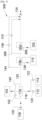
- FIG. 1 shows an aircraft 100 which comprises a fuselage 102 inside which is delimited a cabin including the space where the passengers and the cockpit are seated.
- the aircraft 100 also includes de-icing means, for example to de-ice the wings.
- the cabin and the defrosting means constitute heating devices 104.
- other elements of the aircraft 100 can be integrated into these heating devices 104.
- the aircraft 100 also comprises at least one propulsion system 106 comprising an engine incorporating, among other things, a gearbox, and taking the form of a turbojet or a turboprop operating on dihydrogen which is stored in liquid form in a fuel tank. fuel 108 placed for example in the wings.
- propulsion system 106 comprising an engine incorporating, among other things, a gearbox, and taking the form of a turbojet or a turboprop operating on dihydrogen which is stored in liquid form in a fuel tank.
- fuel 108 placed for example in the wings.
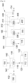
- THE Figs. 2 , 3 And 4 show an aircraft 100, 300, 400 according to different embodiments of the invention.
- the aircraft 100, 300, 400 thus includes the engine 110 and the heating devices 104.
- the propulsion system 106 comprises a fan disposed in a fan channel and intended to generate a flow of air in the engine 110 in a direction of movement of the air in the engine 110, where in known manner, the flow of Air then moves downstream of the fan in a primary vein or in a secondary vein of the motor 110.
- the engine 110 also comprises an engine compressor which comprises a low pressure compressor downstream of the fan and a high pressure compressor downstream of the low pressure compressor, and an engine turbine which comprises a high pressure turbine downstream of the high pressure compressor, and a low pressure turbine downstream of the high pressure turbine.
- the air pushed by the fan and passing through the primary stream passes successively through the low pressure compressor, the high pressure compressor, the high pressure turbine, and the low pressure turbine to be ejected to the outside. Between the high pressure compressor and the high pressure turbine, the air passes through a combustion chamber where it is mixed with dihydrogen in order to burn the latter.
- the high pressure compressor has several compression stages where the pressure increases, from upstream to downstream depending on the direction of movement, from low pressure at the first stage, to high pressure at the last stage, in passing through intermediate pressures in the intermediate stages.
- the aircraft 100, 300, 400 also includes a first air intake 112 intended to take, from the high pressure compressor, air at low pressure or intermediate pressure, a second air intake 114 intended to take, in the high pressure compressor, high pressure air.
- the aircraft 100, 300, 400 also includes a first heat exchanger 116 and a first pipe 118 which passes through the first heat exchanger 116 and supplies the devices to be heated 104 downstream of the first heat exchanger 116 relative to the direction of flow in the first line 118.
- the first pipe 118 Upstream of the first heat exchanger 116 relative to the direction of the air flow in the first pipe 118, the first pipe 118 is divided into two sub-pipes, one of which is fluidly connected to the first air intake 112 and the other of which is fluidly connected to the second air intake 114.
- Each sub-pipe is here equipped with a valve 120, 122 which makes it possible to regulate the passage of air coming from each air intake 112, 114 depending on the needs of the aircraft 100, 300, 400 and for this purpose, the aircraft 100, 300, 400 includes a control unit intended to control the valves 112, 114 in opening and closing.
- the aircraft 100, 300, 400 comprises the fuel tank 108 which makes it possible to store the dihydrogen in liquid form and a fuel pipe 130 which is fluidly connected between the fuel tank 108 and the combustion chamber of the engine 110 for supply dihydrogen from the fuel tank 108.
- At least one pump 132, 134 is arranged on the fuel line 130 to drive the dihydrogen into the fuel line 130.
- a pump 132 is arranged at the outlet of the fuel tank 108 to have sufficient pressure in the fuel pipe 130 and, to have sufficient pressure for the combustion chamber, a pump 134 is arranged downstream of a second fuel pipe. bypass 144 relative to the direction of fuel flow in fuel line 130, where the second bypass line 144 is described below. Optimizing the flow rates and/or pressures of dihydrogen in the fuel line 130 can lead to modifying the positions of the two pumps 132 and 134, as described in the Fig. 3 .
- the first heat exchanger 116 is arranged on the fuel pipe 130 so as to allow a heat exchange between the dihydrogen circulating in the fuel pipe 130 and the air circulating in the first pipe 118. In other words, the heat exchanger fuel 130 passes through the first heat exchanger 116.
- the hot air taken from the air intakes 112 and 114 is cooled as it passes through the first heat exchanger 116 by the dihydrogen taken from the fuel tank 108 which is then reheated and channeled towards the combustion chamber. , while the cooled air is directed towards the devices to be heated 104 through the first pipe 118.
- the temperature of the dihydrogen ensures a drop in the air temperature and the heating of the dihydrogen ensures at least in part its vaporization before its combustion.
- the first heat exchanger 116 is also smaller than that of the state of the art.
- the air intake at the fan channel is reduced at the time of takeoff, which improves the performance of the engine 110.
- the aircraft 100, 300, 400 comprises a second heat exchanger 136 which is intended to carry out a heat exchange between the flow of dihydrogen coming from the first heat exchanger 116 and a flow of oil coming from the engine 110.
- the second heat exchanger 136 is also crossed by the fuel pipe 130 downstream of the first heat exchanger 116 with respect to the direction of the fuel flow in the fuel pipe 130 and by a first oil circuit 138 taking from the oil from the engine 110 and reinjecting this oil into the engine 110 after passing through the second heat exchanger 136.
- the hot oil taken from the engine 110 is cooled as it passes through the second heat exchanger 136 by the dihydrogen circulating in the fuel pipe 130 which is then heated and channeled towards the combustion chamber of the engine 110 while the The cooled oil is directed to the engine 110.
- the exchange of calories causes a lowering of the temperature of the oil and a heating of the dihydrogen before its combustion.
- the aircraft 100, 300, 400 comprises a first diversion pipe 140 fluidly connected to the fuel pipe 130 on either side of the first heat exchanger 116 and a regulation valve 142 controlled in opening and closing by the control unit is installed on the first diversion pipe 140.
- the aircraft 100, 300, 400 in order to regulate the flow of dihydrogen in the second heat exchanger 136, the aircraft 100, 300, 400 includes a second diversion pipe 144 fluidly connected to the fuel pipe 130 on either side of the second heat exchanger 136 and a regulation valve 146 controlled in opening and closing by the control unit is installed on the second diversion pipe 144.
- the aircraft 300 includes an electric generator 302 which generates an electric current to power the aircraft 300.
- the aircraft 300 includes a third heat exchanger 304 which is intended to carry out a thermal exchange between the dihydrogen circulating in the fuel pipe 130 and a flow of oil coming from the electric generator 302.
- the third heat exchanger 304 is crossed by the fuel pipe 130, and by a second oil circuit 306 taking oil from the electric generator 302 and reinjecting this oil into the electric generator 302 after passing through the third heat exchanger 304.
- the hot oil taken from the electric generator 302 is cooled as it passes through the third heat exchanger 304 by the dihydrogen which is then heated and conveyed to the combustion chamber, while the cooled oil is directed towards the generator electric 302.
- the third heat exchanger 304 is arranged downstream of the first and second heat exchangers 116 and 136 with respect to the direction of fuel flow in the fuel line 130, but in a different order is possible.
- the aircraft 300 includes a third diversion pipe 308 fluidly connected to the fuel pipe 130 on either side of the third heat exchanger 304 and a regulation valve 310 controlled in opening and closing by the control unit is installed on the third diversion pipe 308.
- the aircraft 400 comprises a nacelle 402 surrounding the engine 110 and through which circulates a flow of air which is in particular heated by the engine 110.
- the aircraft 400 comprises a fourth heat exchanger 404 which is intended to carry out a heat exchange between the dihydrogen circulating in the fuel pipe 130 and a flow of a fluid heat transfer circulating in a third circuit 406 circulating in the nacelle 402.
- the fourth heat exchanger 404 is crossed by the fuel pipe 130, and by the third circuit 406 in which circulates the heat transfer fluid which is loaded with calories by crossing the nacelle 402 and which discharges its calories by crossing the fourth heat exchanger 404.
- the third circuit 406 can take for example the form of a set of pipes in contact with the motor 110 to carry out an exchange by conduction, and/or the form of a set of pipes in contact with the flow of air circulating in the nacelle 402 to carry out an exchange by convection.
- the heat transfer fluid passes through the nacelle 402, it is loaded with calories which it discharges by passing through the fourth heat exchanger 404 by the dihydrogen which is then heated and conveyed to the combustion chamber, while the heat transfer fluid cools circulates in a loop.
- the fourth heat exchanger 404 is arranged downstream of the first, second and third heat exchangers 116, 136 and 304 with respect to the direction of the fuel flow in the fuel pipe 130 , but a different order is possible.
- the aircraft 400 includes a fourth diversion pipe 408 fluidly connected to the fuel pipe 130 on either side of the fourth heat exchanger 404 and a control valve 410 controlled in opening and closing by the control unit is installed on the fourth diversion pipe 408.
- the second, third and fourth branch pipes 144, 308 and 408 all open into the fuel pipe 130 downstream of the fourth heat exchanger 404 with respect to the direction of the fuel flow in the fuel pipe 130, but it is possible that each pipe of bypass 144, 308, 408 opens into the fuel pipe 130 just downstream of the corresponding heat exchanger 136, 304, 404.
- the temperature of the engine 110 is regulated by the second heat exchanger 136
- the temperature of the engine 110 is regulated by the second heat exchanger 136 and the temperature of the electric generator 302 is regulated by the third heat exchanger 304
- the temperature of the engine 110 is regulated by the second heat exchanger 136
- the temperature of the electric generator 302 is regulated by the third heat exchanger 304
- the temperature of the air flow of the nacelle 402 is regulated by the fourth heat exchanger 404, but it is possible to provide other combinations.
- an accumulator can be installed on the line between the tank 108 and the pump 134.
- Another exchanger can be added along the fuel line 130 between the pumps 132 and 134 in the case where the heat recovered is not yet sufficient to raise the temperature of the fuel before its introduction into the combustion chamber.
- This exchanger which can be activated or deactivated depending on the needs and phases of flight, draws outside air (in the secondary vein for example) to regulate the fuel temperature.
- This exchanger can also be positioned on the third circuit 406 and thus exchange indirectly with the fuel through the heat transfer fluid.
Landscapes
- Engineering & Computer Science (AREA)
- Chemical & Material Sciences (AREA)
- Combustion & Propulsion (AREA)
- Mechanical Engineering (AREA)
- General Engineering & Computer Science (AREA)
- Aviation & Aerospace Engineering (AREA)
- Heat-Exchange Devices With Radiators And Conduit Assemblies (AREA)
- Cooling, Air Intake And Gas Exhaust, And Fuel Tank Arrangements In Propulsion Units (AREA)
Claims (5)
- Luftfahrzeug (100, 300, 400), das aufweist:- einen Motor (110), der einen Hochdruckkompressor mit mehreren Verdichtungsstufen und eine Brennkammer aufweist,- einen Treibstofftank (108), der Diwasserstoff in flüssiger Form enthält,- zu erwärmende Vorrichtungen (104),- einen ersten Lufteinlass (112), der dazu bestimmt ist, im Hochdruckkompressor Luft auf einem niedrigen Druck oder einem mittleren Druck zu entnehmen, einen zweiten Lufteinlass (114), der dazu bestimmt ist, im Hochdruckkompressor Luft auf einem hohen Druck zu entnehmen,- einen ersten Wärmetauscher (116),- eine erste Leitung (118), die den ersten Wärmetauscher (116) durchquert und die dem ersten Wärmetauscher (116) nachgelagerten oder dem ersten Wärmetauscher (116) vorgelagerten zu erwärmenden Vorrichtungen (104) versorgt, wobei die erste Leitung (118) sich in zwei Teilleitungen unterteilt, von denen eine mit dem ersten Lufteinlass (112) in Fluidverbindung steht und die andere mit dem zweiten Lufteinlass (114) in Fluidverbindung steht, und- eine Treibstoffleitung (130), die zwischen dem Treibstofftank (108) und der Brennkammer des Motors (110) in Fluidverbindung steht und den ersten Wärmetauscher (116) durchquert.
- Luftfahrzeug (100, 300, 400) nach Anspruch 1, dadurch gekennzeichnet, dass es dem ersten Tauscher (116) nachgelagert einen zweiten Wärmetauscher (136) aufweist, der von der Treibstoffleitung (130) und von einem ersten Ölkreislauf (138) durchquert wird, der Öl vom Motor (110) entnimmt und dieses Öl nach dem Durchgang durch den zweiten Wärmetauscher (136) wieder in den Motor (110) einspeist.
- Luftfahrzeug (300) nach einem der Ansprüche 1 oder 2, dadurch gekennzeichnet, dass es einen elektrischen Generator (302) und einen dritten Wärmetauscher (304) aufweist, der von der Treibstoffleitung (130) und von einem zweiten Ölkreislauf (306) durchquert wird, der Öl vom elektrischen Generator (302) entnimmt und dieses Öl nach dem Durchgang durch den dritten Wärmetauscher (304) wieder in den elektrischen Generator (302) einspeist.
- Luftfahrzeug (400) nach einem der Ansprüche 1 bis 3, dadurch gekennzeichnet, dass es eine Gondel (402), die den Motor (110) umgibt und durch die ein Luftstrom zirkuliert, und einen vierten Wärmetauscher (404) aufweist, der von der Treibstoffleitung (130) und von einem dritten Kreislauf (406) durchquert wird, in dem ein Wärmeträgerfluid zirkuliert, und wobei der dritte Kreislauf (406) in der Gondel (402) zirkuliert.
- Luftfahrzeug (100, 300, 400) nach einem der Ansprüche 1 bis 4, dadurch gekennzeichnet, dass das Luftfahrzeug (100, 300, 400) für jeden Wärmetauscher (116, 136, 304, 404) eine Bypassleitung (140, 144, 308, 408), die mit der Treibstoffleitung (130) zu beiden Seiten des Wärmetauschers (116, 136, 304, 404) in Fluidverbindung steht, und ein Regelventil (142, 146, 310, 410) aufweist, dessen Öffnen und Schließen gesteuert wird und das auf der Bypassleitung (140, 144, 308, 408) eingebaut ist.
Applications Claiming Priority (1)
| Application Number | Priority Date | Filing Date | Title |
|---|---|---|---|
| FR2101848A FR3120114A1 (fr) | 2021-02-25 | 2021-02-25 | Aéronef comportant un moteur et un système de refroidissement à base de dihydrogène |
Publications (2)
| Publication Number | Publication Date |
|---|---|
| EP4049934A1 EP4049934A1 (de) | 2022-08-31 |
| EP4049934B1 true EP4049934B1 (de) | 2023-12-20 |
Family
ID=74871737
Family Applications (1)
| Application Number | Title | Priority Date | Filing Date |
|---|---|---|---|
| EP22157746.3A Active EP4049934B1 (de) | 2021-02-25 | 2022-02-21 | Luftfahrzeug, das einen motor und ein kühlsystem auf wasserstoffbasis umfasst |
Country Status (4)
| Country | Link |
|---|---|
| US (1) | US20220267021A1 (de) |
| EP (1) | EP4049934B1 (de) |
| CN (1) | CN114954965A (de) |
| FR (1) | FR3120114A1 (de) |
Families Citing this family (9)
| Publication number | Priority date | Publication date | Assignee | Title |
|---|---|---|---|---|
| EP4311779B1 (de) | 2022-07-25 | 2025-05-14 | Airbus Operations | System zur versorgung eines flugzeugmotors mit diwasserstoff |
| US12397915B2 (en) * | 2022-09-02 | 2025-08-26 | General Electric Company | Ice protection systems for aircraft fueled by hydrogen |
| US12583615B2 (en) | 2023-06-30 | 2026-03-24 | Hamilton Sundstrand Corporation | Environmental control system with liquid hydrogen fuel vaporization for a combustion engine |
| US12473093B2 (en) | 2023-06-30 | 2025-11-18 | Hamilton Sundstrand Corporation | Outflow energy recovery system |
| US12583614B2 (en) | 2023-06-30 | 2026-03-24 | Hamilton Sundstrand Corporation | Environmental control system with liquid hydrogen fuel vaporization for a hydrogen fuel cell |
| CN119801731A (zh) | 2023-10-10 | 2025-04-11 | 通用电气阿维奥有限责任公司 | 用于涡轮发动机的润滑系统 |
| IT202300021060A1 (it) * | 2023-10-10 | 2025-04-10 | Ge Avio Srl | Impianto di lubrificazione per un motore a turbina |
| IT202300021018A1 (it) * | 2023-10-10 | 2025-04-10 | Ge Avio Srl | Impianto di lubrificazione per un motore a turbina |
| CN119801730A (zh) | 2023-10-10 | 2025-04-11 | 通用电气阿维奥有限责任公司 | 用于涡轮发动机的润滑系统 |
Citations (1)
| Publication number | Priority date | Publication date | Assignee | Title |
|---|---|---|---|---|
| US20150337730A1 (en) * | 2012-12-28 | 2015-11-26 | General Electric Company | Turbine engine assemblies |
Family Cites Families (11)
| Publication number | Priority date | Publication date | Assignee | Title |
|---|---|---|---|---|
| DE2413507A1 (de) * | 1974-03-20 | 1975-10-02 | Motoren Turbinen Union | Gasturbine fuer kryogenen kraftstoff |
| GB0707319D0 (en) * | 2007-04-17 | 2007-05-23 | Rolls Royce Plc | Apparatus and method of operating a gas turbine engine at start-up |
| FR2961867B1 (fr) * | 2010-06-24 | 2014-06-13 | Snecma | Prelevement d'air a travers le diffuseur d'un compresseur centrifuge d'une turbomachine |
| DE102010034830B4 (de) * | 2010-08-19 | 2012-11-08 | Airbus Operations Gmbh | Klimatisierungssystems für ein Luftfahrzeug mit separatem Kältekreis |
| GB201218815D0 (en) * | 2012-10-19 | 2012-12-05 | Airbus Operations Ltd | Aircraft fuel system with fuel return from engine |
| BR112015023299A2 (pt) * | 2013-03-15 | 2017-07-18 | Gen Electric | método de uso de combustível criogênico e sistema de vaporização de combustível |
| JP6359308B2 (ja) * | 2014-03-25 | 2018-07-18 | 三菱日立パワーシステムズ株式会社 | 配管の破損検出方法及び装置 |
| US10054051B2 (en) * | 2014-04-01 | 2018-08-21 | The Boeing Company | Bleed air systems for use with aircraft and related methods |
| US10823462B2 (en) * | 2016-09-19 | 2020-11-03 | Raytheon Technologies Corporation | Gas turbine engine with transcritical vapor cycle cooling |
| US10914242B2 (en) * | 2017-11-28 | 2021-02-09 | Raytheon Technologies Corporation | Complex air supply system for gas turbine engine and associated aircraft |
| EP3978736B1 (de) * | 2020-09-30 | 2025-03-05 | Rolls-Royce plc | Brennstoffzufuhr |
-
2021
- 2021-02-25 FR FR2101848A patent/FR3120114A1/fr not_active Ceased
-
2022
- 2022-02-21 EP EP22157746.3A patent/EP4049934B1/de active Active
- 2022-02-23 US US17/678,176 patent/US20220267021A1/en not_active Abandoned
- 2022-02-25 CN CN202210182167.9A patent/CN114954965A/zh active Pending
Patent Citations (1)
| Publication number | Priority date | Publication date | Assignee | Title |
|---|---|---|---|---|
| US20150337730A1 (en) * | 2012-12-28 | 2015-11-26 | General Electric Company | Turbine engine assemblies |
Also Published As
| Publication number | Publication date |
|---|---|
| EP4049934A1 (de) | 2022-08-31 |
| CN114954965A (zh) | 2022-08-30 |
| FR3120114A1 (fr) | 2022-08-26 |
| US20220267021A1 (en) | 2022-08-25 |
Similar Documents
| Publication | Publication Date | Title |
|---|---|---|
| EP4049934B1 (de) | Luftfahrzeug, das einen motor und ein kühlsystem auf wasserstoffbasis umfasst | |
| EP2129893B1 (de) | System zur kühlung und temperaturanpassung von geräten in der antriebsanordnung eines flugzeuges | |
| EP4158172B1 (de) | Einrichtung zur versorgung der brennkammer einer turbomaschine mit kryogenem brennstoff | |
| US6651441B2 (en) | Fluid flow system for a gas turbine engine | |
| CN105026726A (zh) | 包括低温燃料系统的涡轮发动机组件 | |
| EP2964906B1 (de) | Triebwerksgondel mit einer ölkühlungsschaltung und einem zwischenwärmetauscher | |
| FR3093766A1 (fr) | Système de conditionnement d’air équipé d’un système de gestion thermique d’huile et d’air pressurisé | |
| EP4423375A1 (de) | System zur aufbereitung von kraftstoff zur versorgung einer flugzeugturbomaschine, flugzeug und verfahren zur verwendung | |
| EP4158171A1 (de) | Kryogenes brennstoffzufuhrsystem für eine turbinenmotorbrennkammer | |
| EP3458695B1 (de) | Umkehrbares system zur ableitung der in einem gasturbinenmotor erzeugten thermischen energie | |
| WO2020178504A2 (fr) | Système de conditionnement d'air d'une cabine d'aéronef comprenant des moyens de réchauffage de l'eau récoltée par la boucle d'extraction d'eau | |
| EP4129828B1 (de) | Flugzeug mit einem wasserstoffversorgungsgerät, in das ein wasserstoffheizsystem integriert ist, das im rumpf des flugzeugs positioniert ist | |
| WO2018055307A1 (fr) | Système de refroidissement d'un circuit d'un premier fluide d'une turbomachine | |
| EP4056475B1 (de) | Luftfahrzeug, das einen motor und ein kühlsystem umfasst | |
| EP4515090B1 (de) | System zur steuerung der temperatur einer wärmeübertragungsflüssigkeit in einem kreislauf und temperatursteuerungsverfahren | |
| EP3992083B1 (de) | Luftfahrzeug, das einen motor und ein kühlsystem für diesen motor umfasst | |
| FR3077604A1 (fr) | Systeme de refroidissement d'air moteur a deux etages de refroidissement et comprenant au moins un echangeur cylindrique | |
| FR3068006A1 (fr) | Systeme de recuperation d'energie thermique d'une boite de tranmission principale de puissance d'un aeronef pour le chauffage l'habitacle de l'aeronef | |
| WO2021099733A1 (fr) | Système de conditionnement d'air d'une cabine d'un véhicule de transport aérien ou ferroviaire utilisant une source d'air pneumatique et thermique distincte de la source d'air de conditionnement | |
| WO2025219675A1 (fr) | Echangeur thermique double paroi pour un systeme de conditionnement de carburant | |
| FR3116082A1 (fr) | Turboréacteur à double flux pourvu de moyens de communication d’air | |
| WO2025078764A1 (fr) | Turbomachine d'aeronef comprenant une pompe a chaleur | |
| FR3137712A1 (fr) | Procédé et système de génération d’une énergie électrique au sein d’une turbomachine | |
| FR3057298A1 (fr) | Ensemble de motorisation a boucle de rankine |
Legal Events
| Date | Code | Title | Description |
|---|---|---|---|
| PUAI | Public reference made under article 153(3) epc to a published international application that has entered the european phase |
Free format text: ORIGINAL CODE: 0009012 |
|
| STAA | Information on the status of an ep patent application or granted ep patent |
Free format text: STATUS: THE APPLICATION HAS BEEN PUBLISHED |
|
| AK | Designated contracting states |
Kind code of ref document: A1 Designated state(s): AL AT BE BG CH CY CZ DE DK EE ES FI FR GB GR HR HU IE IS IT LI LT LU LV MC MK MT NL NO PL PT RO RS SE SI SK SM TR |
|
| STAA | Information on the status of an ep patent application or granted ep patent |
Free format text: STATUS: REQUEST FOR EXAMINATION WAS MADE |
|
| 17P | Request for examination filed |
Effective date: 20230228 |
|
| RBV | Designated contracting states (corrected) |
Designated state(s): AL AT BE BG CH CY CZ DE DK EE ES FI FR GB GR HR HU IE IS IT LI LT LU LV MC MK MT NL NO PL PT RO RS SE SI SK SM TR |
|
| GRAP | Despatch of communication of intention to grant a patent |
Free format text: ORIGINAL CODE: EPIDOSNIGR1 |
|
| STAA | Information on the status of an ep patent application or granted ep patent |
Free format text: STATUS: GRANT OF PATENT IS INTENDED |
|
| RIC1 | Information provided on ipc code assigned before grant |
Ipc: B64D 15/04 20060101ALN20230616BHEP Ipc: F02C 7/224 20060101ALI20230616BHEP Ipc: B64D 33/08 20060101ALI20230616BHEP Ipc: B64D 37/34 20060101AFI20230616BHEP |
|
| INTG | Intention to grant announced |
Effective date: 20230713 |
|
| GRAS | Grant fee paid |
Free format text: ORIGINAL CODE: EPIDOSNIGR3 |
|
| GRAA | (expected) grant |
Free format text: ORIGINAL CODE: 0009210 |
|
| STAA | Information on the status of an ep patent application or granted ep patent |
Free format text: STATUS: THE PATENT HAS BEEN GRANTED |
|
| AK | Designated contracting states |
Kind code of ref document: B1 Designated state(s): AL AT BE BG CH CY CZ DE DK EE ES FI FR GB GR HR HU IE IS IT LI LT LU LV MC MK MT NL NO PL PT RO RS SE SI SK SM TR |
|
| REG | Reference to a national code |
Ref country code: GB Ref legal event code: FG4D Free format text: NOT ENGLISH |
|
| REG | Reference to a national code |
Ref country code: CH Ref legal event code: EP |
|
| REG | Reference to a national code |
Ref country code: DE Ref legal event code: R096 Ref document number: 602022001323 Country of ref document: DE |
|
| REG | Reference to a national code |
Ref country code: IE Ref legal event code: FG4D Free format text: LANGUAGE OF EP DOCUMENT: FRENCH |
|
| PG25 | Lapsed in a contracting state [announced via postgrant information from national office to epo] |
Ref country code: GR Free format text: LAPSE BECAUSE OF FAILURE TO SUBMIT A TRANSLATION OF THE DESCRIPTION OR TO PAY THE FEE WITHIN THE PRESCRIBED TIME-LIMIT Effective date: 20240321 |
|
| REG | Reference to a national code |
Ref country code: LT Ref legal event code: MG9D |
|
| PG25 | Lapsed in a contracting state [announced via postgrant information from national office to epo] |
Ref country code: LT Free format text: LAPSE BECAUSE OF FAILURE TO SUBMIT A TRANSLATION OF THE DESCRIPTION OR TO PAY THE FEE WITHIN THE PRESCRIBED TIME-LIMIT Effective date: 20231220 |
|
| REG | Reference to a national code |
Ref country code: NL Ref legal event code: MP Effective date: 20231220 |
|
| PG25 | Lapsed in a contracting state [announced via postgrant information from national office to epo] |
Ref country code: ES Free format text: LAPSE BECAUSE OF FAILURE TO SUBMIT A TRANSLATION OF THE DESCRIPTION OR TO PAY THE FEE WITHIN THE PRESCRIBED TIME-LIMIT Effective date: 20231220 |
|
| PG25 | Lapsed in a contracting state [announced via postgrant information from national office to epo] |
Ref country code: LT Free format text: LAPSE BECAUSE OF FAILURE TO SUBMIT A TRANSLATION OF THE DESCRIPTION OR TO PAY THE FEE WITHIN THE PRESCRIBED TIME-LIMIT Effective date: 20231220 Ref country code: GR Free format text: LAPSE BECAUSE OF FAILURE TO SUBMIT A TRANSLATION OF THE DESCRIPTION OR TO PAY THE FEE WITHIN THE PRESCRIBED TIME-LIMIT Effective date: 20240321 Ref country code: FI Free format text: LAPSE BECAUSE OF FAILURE TO SUBMIT A TRANSLATION OF THE DESCRIPTION OR TO PAY THE FEE WITHIN THE PRESCRIBED TIME-LIMIT Effective date: 20231220 Ref country code: ES Free format text: LAPSE BECAUSE OF FAILURE TO SUBMIT A TRANSLATION OF THE DESCRIPTION OR TO PAY THE FEE WITHIN THE PRESCRIBED TIME-LIMIT Effective date: 20231220 Ref country code: BG Free format text: LAPSE BECAUSE OF FAILURE TO SUBMIT A TRANSLATION OF THE DESCRIPTION OR TO PAY THE FEE WITHIN THE PRESCRIBED TIME-LIMIT Effective date: 20240320 |
|
| REG | Reference to a national code |
Ref country code: AT Ref legal event code: MK05 Ref document number: 1642275 Country of ref document: AT Kind code of ref document: T Effective date: 20231220 |
|
| PG25 | Lapsed in a contracting state [announced via postgrant information from national office to epo] |
Ref country code: NL Free format text: LAPSE BECAUSE OF FAILURE TO SUBMIT A TRANSLATION OF THE DESCRIPTION OR TO PAY THE FEE WITHIN THE PRESCRIBED TIME-LIMIT Effective date: 20231220 |
|
| PG25 | Lapsed in a contracting state [announced via postgrant information from national office to epo] |
Ref country code: SE Free format text: LAPSE BECAUSE OF FAILURE TO SUBMIT A TRANSLATION OF THE DESCRIPTION OR TO PAY THE FEE WITHIN THE PRESCRIBED TIME-LIMIT Effective date: 20231220 Ref country code: RS Free format text: LAPSE BECAUSE OF FAILURE TO SUBMIT A TRANSLATION OF THE DESCRIPTION OR TO PAY THE FEE WITHIN THE PRESCRIBED TIME-LIMIT Effective date: 20231220 Ref country code: NO Free format text: LAPSE BECAUSE OF FAILURE TO SUBMIT A TRANSLATION OF THE DESCRIPTION OR TO PAY THE FEE WITHIN THE PRESCRIBED TIME-LIMIT Effective date: 20240320 Ref country code: NL Free format text: LAPSE BECAUSE OF FAILURE TO SUBMIT A TRANSLATION OF THE DESCRIPTION OR TO PAY THE FEE WITHIN THE PRESCRIBED TIME-LIMIT Effective date: 20231220 Ref country code: LV Free format text: LAPSE BECAUSE OF FAILURE TO SUBMIT A TRANSLATION OF THE DESCRIPTION OR TO PAY THE FEE WITHIN THE PRESCRIBED TIME-LIMIT Effective date: 20231220 Ref country code: HR Free format text: LAPSE BECAUSE OF FAILURE TO SUBMIT A TRANSLATION OF THE DESCRIPTION OR TO PAY THE FEE WITHIN THE PRESCRIBED TIME-LIMIT Effective date: 20231220 |
|
| PG25 | Lapsed in a contracting state [announced via postgrant information from national office to epo] |
Ref country code: IS Free format text: LAPSE BECAUSE OF FAILURE TO SUBMIT A TRANSLATION OF THE DESCRIPTION OR TO PAY THE FEE WITHIN THE PRESCRIBED TIME-LIMIT Effective date: 20240420 |
|
| PG25 | Lapsed in a contracting state [announced via postgrant information from national office to epo] |
Ref country code: CZ Free format text: LAPSE BECAUSE OF FAILURE TO SUBMIT A TRANSLATION OF THE DESCRIPTION OR TO PAY THE FEE WITHIN THE PRESCRIBED TIME-LIMIT Effective date: 20231220 Ref country code: AT Free format text: LAPSE BECAUSE OF FAILURE TO SUBMIT A TRANSLATION OF THE DESCRIPTION OR TO PAY THE FEE WITHIN THE PRESCRIBED TIME-LIMIT Effective date: 20231220 |
|
| PG25 | Lapsed in a contracting state [announced via postgrant information from national office to epo] |
Ref country code: SK Free format text: LAPSE BECAUSE OF FAILURE TO SUBMIT A TRANSLATION OF THE DESCRIPTION OR TO PAY THE FEE WITHIN THE PRESCRIBED TIME-LIMIT Effective date: 20231220 |
|
| PG25 | Lapsed in a contracting state [announced via postgrant information from national office to epo] |
Ref country code: SM Free format text: LAPSE BECAUSE OF FAILURE TO SUBMIT A TRANSLATION OF THE DESCRIPTION OR TO PAY THE FEE WITHIN THE PRESCRIBED TIME-LIMIT Effective date: 20231220 Ref country code: SK Free format text: LAPSE BECAUSE OF FAILURE TO SUBMIT A TRANSLATION OF THE DESCRIPTION OR TO PAY THE FEE WITHIN THE PRESCRIBED TIME-LIMIT Effective date: 20231220 Ref country code: RO Free format text: LAPSE BECAUSE OF FAILURE TO SUBMIT A TRANSLATION OF THE DESCRIPTION OR TO PAY THE FEE WITHIN THE PRESCRIBED TIME-LIMIT Effective date: 20231220 Ref country code: IT Free format text: LAPSE BECAUSE OF FAILURE TO SUBMIT A TRANSLATION OF THE DESCRIPTION OR TO PAY THE FEE WITHIN THE PRESCRIBED TIME-LIMIT Effective date: 20231220 Ref country code: IS Free format text: LAPSE BECAUSE OF FAILURE TO SUBMIT A TRANSLATION OF THE DESCRIPTION OR TO PAY THE FEE WITHIN THE PRESCRIBED TIME-LIMIT Effective date: 20240420 Ref country code: EE Free format text: LAPSE BECAUSE OF FAILURE TO SUBMIT A TRANSLATION OF THE DESCRIPTION OR TO PAY THE FEE WITHIN THE PRESCRIBED TIME-LIMIT Effective date: 20231220 Ref country code: CZ Free format text: LAPSE BECAUSE OF FAILURE TO SUBMIT A TRANSLATION OF THE DESCRIPTION OR TO PAY THE FEE WITHIN THE PRESCRIBED TIME-LIMIT Effective date: 20231220 Ref country code: AT Free format text: LAPSE BECAUSE OF FAILURE TO SUBMIT A TRANSLATION OF THE DESCRIPTION OR TO PAY THE FEE WITHIN THE PRESCRIBED TIME-LIMIT Effective date: 20231220 |
|
| PG25 | Lapsed in a contracting state [announced via postgrant information from national office to epo] |
Ref country code: PL Free format text: LAPSE BECAUSE OF FAILURE TO SUBMIT A TRANSLATION OF THE DESCRIPTION OR TO PAY THE FEE WITHIN THE PRESCRIBED TIME-LIMIT Effective date: 20231220 Ref country code: PT Free format text: LAPSE BECAUSE OF FAILURE TO SUBMIT A TRANSLATION OF THE DESCRIPTION OR TO PAY THE FEE WITHIN THE PRESCRIBED TIME-LIMIT Effective date: 20240422 |
|
| PG25 | Lapsed in a contracting state [announced via postgrant information from national office to epo] |
Ref country code: PT Free format text: LAPSE BECAUSE OF FAILURE TO SUBMIT A TRANSLATION OF THE DESCRIPTION OR TO PAY THE FEE WITHIN THE PRESCRIBED TIME-LIMIT Effective date: 20240422 Ref country code: PL Free format text: LAPSE BECAUSE OF FAILURE TO SUBMIT A TRANSLATION OF THE DESCRIPTION OR TO PAY THE FEE WITHIN THE PRESCRIBED TIME-LIMIT Effective date: 20231220 |
|
| REG | Reference to a national code |
Ref country code: DE Ref legal event code: R097 Ref document number: 602022001323 Country of ref document: DE |
|
| PG25 | Lapsed in a contracting state [announced via postgrant information from national office to epo] |
Ref country code: MC Free format text: LAPSE BECAUSE OF FAILURE TO SUBMIT A TRANSLATION OF THE DESCRIPTION OR TO PAY THE FEE WITHIN THE PRESCRIBED TIME-LIMIT Effective date: 20231220 |
|
| PG25 | Lapsed in a contracting state [announced via postgrant information from national office to epo] |
Ref country code: DK Free format text: LAPSE BECAUSE OF FAILURE TO SUBMIT A TRANSLATION OF THE DESCRIPTION OR TO PAY THE FEE WITHIN THE PRESCRIBED TIME-LIMIT Effective date: 20231220 |
|
| PG25 | Lapsed in a contracting state [announced via postgrant information from national office to epo] |
Ref country code: LU Free format text: LAPSE BECAUSE OF NON-PAYMENT OF DUE FEES Effective date: 20240221 |
|
| PLBE | No opposition filed within time limit |
Free format text: ORIGINAL CODE: 0009261 |
|
| STAA | Information on the status of an ep patent application or granted ep patent |
Free format text: STATUS: NO OPPOSITION FILED WITHIN TIME LIMIT |
|
| PG25 | Lapsed in a contracting state [announced via postgrant information from national office to epo] |
Ref country code: SI Free format text: LAPSE BECAUSE OF FAILURE TO SUBMIT A TRANSLATION OF THE DESCRIPTION OR TO PAY THE FEE WITHIN THE PRESCRIBED TIME-LIMIT Effective date: 20231220 |
|
| PG25 | Lapsed in a contracting state [announced via postgrant information from national office to epo] |
Ref country code: SI Free format text: LAPSE BECAUSE OF FAILURE TO SUBMIT A TRANSLATION OF THE DESCRIPTION OR TO PAY THE FEE WITHIN THE PRESCRIBED TIME-LIMIT Effective date: 20231220 Ref country code: LU Free format text: LAPSE BECAUSE OF NON-PAYMENT OF DUE FEES Effective date: 20240221 Ref country code: DK Free format text: LAPSE BECAUSE OF FAILURE TO SUBMIT A TRANSLATION OF THE DESCRIPTION OR TO PAY THE FEE WITHIN THE PRESCRIBED TIME-LIMIT Effective date: 20231220 |
|
| 26N | No opposition filed |
Effective date: 20240923 |
|
| REG | Reference to a national code |
Ref country code: BE Ref legal event code: MM Effective date: 20240229 |
|
| PG25 | Lapsed in a contracting state [announced via postgrant information from national office to epo] |
Ref country code: BE Free format text: LAPSE BECAUSE OF NON-PAYMENT OF DUE FEES Effective date: 20240229 |
|
| PG25 | Lapsed in a contracting state [announced via postgrant information from national office to epo] |
Ref country code: IE Free format text: LAPSE BECAUSE OF NON-PAYMENT OF DUE FEES Effective date: 20240221 |
|
| PG25 | Lapsed in a contracting state [announced via postgrant information from national office to epo] |
Ref country code: IE Free format text: LAPSE BECAUSE OF NON-PAYMENT OF DUE FEES Effective date: 20240221 Ref country code: BE Free format text: LAPSE BECAUSE OF NON-PAYMENT OF DUE FEES Effective date: 20240229 |
|
| PG25 | Lapsed in a contracting state [announced via postgrant information from national office to epo] |
Ref country code: CY Free format text: LAPSE BECAUSE OF FAILURE TO SUBMIT A TRANSLATION OF THE DESCRIPTION OR TO PAY THE FEE WITHIN THE PRESCRIBED TIME-LIMIT; INVALID AB INITIO Effective date: 20220221 |
|
| REG | Reference to a national code |
Ref country code: CH Ref legal event code: PL |
|
| PG25 | Lapsed in a contracting state [announced via postgrant information from national office to epo] |
Ref country code: CH Free format text: LAPSE BECAUSE OF NON-PAYMENT OF DUE FEES Effective date: 20250228 |
|
| PG25 | Lapsed in a contracting state [announced via postgrant information from national office to epo] |
Ref country code: TR Free format text: LAPSE BECAUSE OF FAILURE TO SUBMIT A TRANSLATION OF THE DESCRIPTION OR TO PAY THE FEE WITHIN THE PRESCRIBED TIME-LIMIT Effective date: 20231220 |
|
| PGFP | Annual fee paid to national office [announced via postgrant information from national office to epo] |
Ref country code: GB Payment date: 20260220 Year of fee payment: 5 |
|
| PGFP | Annual fee paid to national office [announced via postgrant information from national office to epo] |
Ref country code: DE Payment date: 20260218 Year of fee payment: 5 |
|
| PGFP | Annual fee paid to national office [announced via postgrant information from national office to epo] |
Ref country code: FR Payment date: 20260219 Year of fee payment: 5 |