EP2964906B1 - Triebwerksgondel mit einer ölkühlungsschaltung und einem zwischenwärmetauscher - Google Patents
Triebwerksgondel mit einer ölkühlungsschaltung und einem zwischenwärmetauscher Download PDFInfo
- Publication number
- EP2964906B1 EP2964906B1 EP14715041.1A EP14715041A EP2964906B1 EP 2964906 B1 EP2964906 B1 EP 2964906B1 EP 14715041 A EP14715041 A EP 14715041A EP 2964906 B1 EP2964906 B1 EP 2964906B1
- Authority
- EP
- European Patent Office
- Prior art keywords
- air
- nacelle
- exchanger
- network
- oil
- Prior art date
- Legal status (The legal status is an assumption and is not a legal conclusion. Google has not performed a legal analysis and makes no representation as to the accuracy of the status listed.)
- Active
Links
- 238000001816 cooling Methods 0.000 title description 9
- 239000012530 fluid Substances 0.000 claims description 33
- 238000011144 upstream manufacturing Methods 0.000 claims description 10
- 230000002093 peripheral effect Effects 0.000 claims description 7
- 230000000740 bleeding effect Effects 0.000 claims 4
- 239000002826 coolant Substances 0.000 claims 1
- 238000005192 partition Methods 0.000 claims 1
- 239000003921 oil Substances 0.000 description 57
- 239000010705 motor oil Substances 0.000 description 11
- 235000021183 entrée Nutrition 0.000 description 8
- 239000000314 lubricant Substances 0.000 description 7
- 238000010257 thawing Methods 0.000 description 7
- 238000005070 sampling Methods 0.000 description 6
- 210000003462 vein Anatomy 0.000 description 6
- RTAQQCXQSZGOHL-UHFFFAOYSA-N Titanium Chemical compound [Ti] RTAQQCXQSZGOHL-UHFFFAOYSA-N 0.000 description 2
- XAGFODPZIPBFFR-UHFFFAOYSA-N aluminium Chemical compound [Al] XAGFODPZIPBFFR-UHFFFAOYSA-N 0.000 description 2
- 229910052782 aluminium Inorganic materials 0.000 description 2
- 230000005540 biological transmission Effects 0.000 description 2
- 238000005461 lubrication Methods 0.000 description 2
- 229910052719 titanium Inorganic materials 0.000 description 2
- 239000010936 titanium Substances 0.000 description 2
- 230000015572 biosynthetic process Effects 0.000 description 1
- 239000012809 cooling fluid Substances 0.000 description 1
- 230000037406 food intake Effects 0.000 description 1
- 239000000446 fuel Substances 0.000 description 1
- 239000000463 material Substances 0.000 description 1
- 238000000034 method Methods 0.000 description 1
- 210000000056 organ Anatomy 0.000 description 1
- 230000001105 regulatory effect Effects 0.000 description 1
Images


Classifications
-
- F—MECHANICAL ENGINEERING; LIGHTING; HEATING; WEAPONS; BLASTING
- F02—COMBUSTION ENGINES; HOT-GAS OR COMBUSTION-PRODUCT ENGINE PLANTS
- F02C—GAS-TURBINE PLANTS; AIR INTAKES FOR JET-PROPULSION PLANTS; CONTROLLING FUEL SUPPLY IN AIR-BREATHING JET-PROPULSION PLANTS
- F02C7/00—Features, components parts, details or accessories, not provided for in, or of interest apart form groups F02C1/00 - F02C6/00; Air intakes for jet-propulsion plants
- F02C7/12—Cooling of plants
- F02C7/14—Cooling of plants of fluids in the plant, e.g. lubricant or fuel
-
- B—PERFORMING OPERATIONS; TRANSPORTING
- B64—AIRCRAFT; AVIATION; COSMONAUTICS
- B64D—EQUIPMENT FOR FITTING IN OR TO AIRCRAFT; FLIGHT SUITS; PARACHUTES; ARRANGEMENT OR MOUNTING OF POWER PLANTS OR PROPULSION TRANSMISSIONS IN AIRCRAFT
- B64D33/00—Arrangements in aircraft of power plant parts or auxiliaries not otherwise provided for
- B64D33/02—Arrangements in aircraft of power plant parts or auxiliaries not otherwise provided for of combustion air intakes
-
- F—MECHANICAL ENGINEERING; LIGHTING; HEATING; WEAPONS; BLASTING
- F01—MACHINES OR ENGINES IN GENERAL; ENGINE PLANTS IN GENERAL; STEAM ENGINES
- F01D—NON-POSITIVE DISPLACEMENT MACHINES OR ENGINES, e.g. STEAM TURBINES
- F01D25/00—Component parts, details, or accessories, not provided for in, or of interest apart from, other groups
- F01D25/08—Cooling; Heating; Heat-insulation
- F01D25/12—Cooling
-
- F—MECHANICAL ENGINEERING; LIGHTING; HEATING; WEAPONS; BLASTING
- F01—MACHINES OR ENGINES IN GENERAL; ENGINE PLANTS IN GENERAL; STEAM ENGINES
- F01D—NON-POSITIVE DISPLACEMENT MACHINES OR ENGINES, e.g. STEAM TURBINES
- F01D25/00—Component parts, details, or accessories, not provided for in, or of interest apart from, other groups
- F01D25/24—Casings; Casing parts, e.g. diaphragms, casing fastenings
-
- B—PERFORMING OPERATIONS; TRANSPORTING
- B64—AIRCRAFT; AVIATION; COSMONAUTICS
- B64D—EQUIPMENT FOR FITTING IN OR TO AIRCRAFT; FLIGHT SUITS; PARACHUTES; ARRANGEMENT OR MOUNTING OF POWER PLANTS OR PROPULSION TRANSMISSIONS IN AIRCRAFT
- B64D33/00—Arrangements in aircraft of power plant parts or auxiliaries not otherwise provided for
- B64D33/02—Arrangements in aircraft of power plant parts or auxiliaries not otherwise provided for of combustion air intakes
- B64D2033/0233—Arrangements in aircraft of power plant parts or auxiliaries not otherwise provided for of combustion air intakes comprising de-icing means
-
- F—MECHANICAL ENGINEERING; LIGHTING; HEATING; WEAPONS; BLASTING
- F05—INDEXING SCHEMES RELATING TO ENGINES OR PUMPS IN VARIOUS SUBCLASSES OF CLASSES F01-F04
- F05D—INDEXING SCHEME FOR ASPECTS RELATING TO NON-POSITIVE-DISPLACEMENT MACHINES OR ENGINES, GAS-TURBINES OR JET-PROPULSION PLANTS
- F05D2220/00—Application
- F05D2220/30—Application in turbines
- F05D2220/32—Application in turbines in gas turbines
- F05D2220/323—Application in turbines in gas turbines for aircraft propulsion, e.g. jet engines
-
- F—MECHANICAL ENGINEERING; LIGHTING; HEATING; WEAPONS; BLASTING
- F05—INDEXING SCHEMES RELATING TO ENGINES OR PUMPS IN VARIOUS SUBCLASSES OF CLASSES F01-F04
- F05D—INDEXING SCHEME FOR ASPECTS RELATING TO NON-POSITIVE-DISPLACEMENT MACHINES OR ENGINES, GAS-TURBINES OR JET-PROPULSION PLANTS
- F05D2260/00—Function
- F05D2260/20—Heat transfer, e.g. cooling
- F05D2260/213—Heat transfer, e.g. cooling by the provision of a heat exchanger within the cooling circuit
-
- Y—GENERAL TAGGING OF NEW TECHNOLOGICAL DEVELOPMENTS; GENERAL TAGGING OF CROSS-SECTIONAL TECHNOLOGIES SPANNING OVER SEVERAL SECTIONS OF THE IPC; TECHNICAL SUBJECTS COVERED BY FORMER USPC CROSS-REFERENCE ART COLLECTIONS [XRACs] AND DIGESTS
- Y02—TECHNOLOGIES OR APPLICATIONS FOR MITIGATION OR ADAPTATION AGAINST CLIMATE CHANGE
- Y02T—CLIMATE CHANGE MITIGATION TECHNOLOGIES RELATED TO TRANSPORTATION
- Y02T50/00—Aeronautics or air transport
- Y02T50/60—Efficient propulsion technologies, e.g. for aircraft
Definitions
- the present invention relates to a turbine engine nacelle equipped with a motor oil cooling system.
- An aircraft is propelled by one or more propulsion units each comprising a turbine engine housed in a tubular nacelle.
- Each propulsion unit is attached to the aircraft by a mast located generally under or on a wing or at the fuselage.
- Upstream means what comes before the point or element considered, in the direction of the flow of air in a turbine engine, and downstream what comes after the point or element considered, in the direction of the flow of the air in the turbine engine.
- a nacelle generally has a structure comprising an air inlet upstream of the engine, a median section intended to surround a fan or the compressors of the turbine engine and its casing, a downstream section capable of housing thrust reverser means and intended to surround the turbine engine gas generator, and is generally terminated by an ejection nozzle whose output is located downstream of the turbine engine.
- the space between the nacelle and the turbine engine is called secondary vein.
- the turbine engine comprises a set of blades (compressor and possibly fan or non-ttled propeller) rotated by a gas generator through a set of transmission means.
- a lubricant distribution system is provided to ensure good lubrication of these transmission means and any other accessory such as electric generators, and cool.
- the lubricant must then also be cooled by a heat exchanger.
- a first known method is to cool the lubricant by circulation through an air / oil exchanger using air taken from a secondary vein (so-called cold flow) of the nacelle or one of the first compressor stages.
- ice can form on the nacelle, in particular at the outer surface of the air inlet lip fitted to the inlet section of the engine. air.
- frost changes the aerodynamic properties of the air intake and disturbs the flow of air to the blower.
- frost on the nacelle's air inlet and the ingestion of ice by the engine in the event of ice blocks being detached can damage the engine or wing, and pose a risk to the safety of the engine. flight.
- Another solution for de-icing the outer surface of the nacelle is to prevent ice from forming on this external surface by maintaining the relevant surface at a sufficient temperature.
- the heat of the lubricant can be used to heat the external surfaces of the nacelle, the lubricant being thereby cooled and able to be reused in the lubrication circuit.
- the document EP1479889 describes a de-icing system of a turbojet nacelle air inlet structure using a air / oil exchanger in a closed circuit, the heated interior air of the air intake structure being forced convection by a fan.
- the air intake structure is hollow and forms a defrost air circulation closed chamber heated by the exchanger disposed within this chamber.
- the thermal energy available for defrosting depends on the temperature of the lubricant.
- the exchange surface of the air intake structure is fixed and limited and the energy actually dissipated depends essentially on the heat required for deicing and thus on the external conditions.
- the present invention aims to provide a device free from the aforementioned drawbacks.
- the subject of the present invention is an aircraft nacelle comprising: an external aerodynamic wall comprising an upstream air inlet lip, an internal aerodynamic wall, the air inlet lip connecting upstream the two outer and inner aerodynamic walls, a front wall located immediately downstream of the lip and connecting the two outer and inner aerodynamic walls, a circulation network of a first cooling fluid of a second fluid comprising at least two heat exchangers; air / oil type heat and at least one air / air type exchanger, noteworthy in that the circulation network (1) comprises at least one dynamic scoop (112) for taking air from outside the nacelle (100), at least one cold air bleed port (121) from a fan (130) and at least one exhaust port (113) out of the nacelle (100).
- the air intake lip may or may not be integrated with the external aerodynamic wall of the aircraft nacelle.
- This solution optimizes the cooling of the second fluid while minimizing the pressure losses of the nacelle, it allows in some cases to defrost in addition to the air intake lip.
- the pressure taken from the outside, at high speed is sufficient to supply the two air / oil type exchangers in series, the air / air type exchanger makes it possible to lower the temperature at the inlet of the second exchanger in which the air enters.
- the pressure taken from the fan makes it possible to feed only one of the two exchangers, which are then fed in parallel.
- the proposed solution allows to halve the air flow taken and thus halve the losses related to the oil cooling.
- the solution makes it possible to reduce the overall consumption of the aircraft from 0.25% to 0.4% compared to a sampling cooling only in the secondary vein.
- it then reduces the temperature seen by the lip air intake, thus reducing recurring problems of fatigue, and by the upstream zone of the external aerodynamic wall, the temperature of said zone not then exceeding the maximum temperature of the oil of a turbomachine, typically ° C, which allows to realize a front wall of air intake lip made of aluminum rather than titanium.
- the first fluid is substantially composed of air
- the second fluid consists substantially of a motor oil chosen from those commonly used in the aeronautical field.
- the first fluid and the second fluid may consist substantially of any other material that would be suitable for their joint use in the aeronautical field.
- pipe 19 the pipes connecting the different elements of the different networks 1 of air circulation.
- controlled valve means a valve acting as a gate valve, actuator or not, means by dynamic bailer a bailer preferably equipped with at least one regulating valve.
- the first network 1 is included in a nacelle 100 of aircraft.
- the nacelle 100 comprises an outer aerodynamic wall 110 comprising an upstream air inlet lip 111, an internal aerodynamic wall 120, the air inlet lip 111 connecting upstream the two external aerodynamic walls 110 and internal 120.
- the first air circulation network 1 for engine oil cooling comprises two air / oil heat exchangers (respectively 2 and 3), and an air / air exchanger 4.
- the first network 1 comprises non-return valves allowing air circulation only in one direction (respectively 5, 6, and 7), controlled valves (respectively 8 and 9), and the pipe 19.
- the valves 5, 6, 7, 8 and 9 serve to control the flow of air in the first network 1.
- the air / air exchanger 4 is a surface exchanger having an exchange surface 10 made from the outer aerodynamic wall 110 of the nacelle 100.
- the air / air exchanger 4 also comprises a confined space 11, comprising an air intake. 12 and an air outlet 13 of the first fluid, enclosed by the exchange surface 10 and a peripheral wall 14.
- the air / air exchanger 4 also comprises an intermediate wall 15 dividing the confined space 11 into two volumes in such a way that its average plane is substantially parallel to the mean plane of the exchange surface 10, and that one of the volumes, said upper volume 16, is delimited by the exchange surface 10, the peripheral wall 14 and the intermediate wall 15, and the other volume, said lower volume 17, is delimited by the peripheral wall 14 and the intermediate wall 15.
- the intermediate wall 15 is pierced with a plurality of orifices 18.
- the lower volume 17 communicates with the entrance e air 12, and the upper volume 16 communicates with the air outlet 13.
- the air / air exchanger 4 may also comprise only an exchange surface 10 in contact with which comes a duct 19 of the first circuit 1 in order to cool the air circulating in the first network 1 and leaving the air exchanger / oil 2 to penetrate cooled in the air / oil exchanger 3.
- the outer aerodynamic wall 110 of the nacelle comprises a dynamic scoop 112 for withdrawing air coming from the outside of the nacelle and an outlet orifice 113 for air heated out of the nacelle 100 after passing through the first network 1. .
- the internal aerodynamic wall 120 comprises a cold air withdrawal orifice 121 coming from a fan 130 of the aircraft by means of the controlled valve 8 of the first network 1, called the fan duct 121.
- the operation of the first network 1 is described in case of high speed of the aircraft.
- the controlled valves 8 and 9 are closed as well as the non-return valve 6.
- the air taken by the dynamic scoop 112 comes from outside the basket 100, so it is cold.
- the air passes through the non-return valve 5 of the first network 1, the pipe 19, the air / oil exchanger 2 where it recovers the heat of the oil, it then enters the air / air exchanger 4 by the air inlet 12.
- the air circulates from the air inlet 12 in the lower volume 17 and through the intermediate wall 15 through the orifices 18 to reach the upper volume 16.
- the exchange surface 10 which is a heat exchange surface by impact or simple circulation of the fluids.
- the air outside the nacelle 100 is cold and thus cools the exchange surface 10, which itself cools the air in the upper volume 16.
- the cooled air flowing in the upper volume 16 enters the pipe 19 through the air outlet 13 this time, and successively passes through the non-return valve 7, the air / oil exchanger 3 where it recovers heat from the oil finally out of the nacelle 100 through the outlet port 113 of the nacelle 100.
- the operation of the first network 1 is described in case of low speed of the aircraft.
- the air is taken from the fan 130 of the nacelle 100, so it is also cold.
- the check valves 5 and 7 are closed.
- the air enters through the blower sample 121 of the internal aerodynamic wall 120 in the pipe 19 of the first network 1, and passes through the controlled valve 8, electric or pneumatic.
- the pipe 19 splits to divide the air flow in two, a first part of the air having passed the controlled valve then goes to the air / oil exchanger 2 while a second part is directed to the air / oil exchanger 3.
- the second part of the air enters directly into the air / oil exchanger 3 and then to the outlet orifice 113.
- the air intake lip 111 acts as an air / air exchanger 4.
- the second network 1 comprises five controlled valves 8, 9, 20, 21 and 22; three non-return valves 5, 6 and 23; two air / oil exchangers 2 and 3; an air / air exchanger 4.
- the nacelle 100 comprises a means for withdrawing hot air from a compressor of the aircraft, said compressor sample 122, so as to allow the supply of hot air to the air intake lip 111.
- the sampling compressor 122 is connected to the controlled valve 21 which itself is directly connected to the air / air exchanger 4 via the orifice 13.
- the air / air exchanger 4 comprises three air inlet and outlet ports, an air outlet 24 giving directly to the outlet orifice 113 of the nacelle 100 via the controlled valve 22, another orifice is the orifice 13 giving on the air / oil exchanger 3, then serving as an air outlet, and on the sampling compressor 122 via the controlled valve 21, then serving hot air inlet from the compressor (not shown).
- the third orifice is the air inlet 12 of air coming from the air / oil exchanger 2.
- the air / air exchanger 4 operates in substantially the same manner as that described in the previous embodiment (first network 1).
- the air intake lip 111 acts as an air / air exchanger 4.
- the air enters through the orifice 13 or through the air inlet 12 and out through the outlet orifice 24 or through the orifice 13 according to the operating mode of the second network 1.
- the controlled valves 8, 9, 21 and 22 are closed, as well as the non-return valve 6.
- the air enters through the dynamic bailer 112 in the pipe 19; coming from outside the pod 100, the air is cold.
- the air successively passes through the non-return valve 5, the air / oil exchanger 2 where it heats up the heat emitted by the engine oil, the non-return valve 23, the air inlet 12 air / air exchanger 4 where it cools, the orifice 13, the controlled valve 20, the air / oil exchanger 3 where it heats up the heat emitted by the engine oil, and the outlet orifice 113 of the outer aerodynamic wall 110 of the nacelle 100.
- the controlled valves 9, 20 and 21 are closed as well as the non-return valve 5.
- the pipe 19 splits to divide the air flow in two, a first portion of the air having passed the controlled valve 8 then directs to the air / oil exchanger 2 while a second part goes to the air / oil exchanger 3.
- the first part of the air passes through the non-return valve 6, once the air has entered the air / oil exchanger 2, it heats up and passes then through the non-return valve 23, enters the air / air heat exchanger 4 through the air inlet 12 to be immediately discharged through the outlet port 24 to the outlet port 113 of the outer aerodynamic wall 110 through the controlled valve 22.
- the second part of the air enters directly into the air / oil exchanger 3, warms up therein, and is then discharged through the outlet orifice 113.
- the controlled valve 20 is closed as well as the non-return valves 5 and 23.
- the pipe 19 splits to divide the air flow in two, a first part of the air having passed the controlled valve 8 then goes to the air / oil exchanger 2 while a second part is directs to the air / oil exchanger 3.
- the first part of the air passes through a non-return valve 6, once the air has entered the air / oil exchanger 2, it warms up and is then discharged to the outlet port 113 through the controlled valve 9.
- the second part of the air enters directly into the air / oil exchanger 3, heats up, and then discharged through the outlet orifice 113.
- This air then passes through the controlled valve 21 and then goes directly to the orifice 13 and is injected under high pressure into the air inlet lip 111 acting as an air / air exchanger 4.
- the air thus injected under high pressure performs several revolutions along the circumference of the air inlet lip 111 to de-ice the entire air inlet lip 111, then it is discharged to the outlet port 113 through the controlled valve 22 .
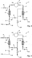
- the third network 1 has the same structure as the second network ( Fig. 4, 5 , 6 , 8 ) in which is added a second air / air exchanger 25 and an additional non-return valve 26.
- an air intake lip 111 of an outer aerodynamic wall 110 of a nacelle 100 in which an air / air exchanger 4 is installed is described.
- the air / air exchanger 4 of the figure 10 is carried out on the same principle as that of the figure 1 . Indeed, it comprises the exchange surface 10 and the peripheral wall 14, or the front wall of the air inlet lip 11 delimiting a confined space 11, the intermediate wall 15 dividing this confined space into two parts, the upper volume 16 and the lower volume 17, the intermediate wall 15 is pierced with a plurality of orifices 18.
- the lower volume 17 communicates with the air inlet 12, and the upper volume 16 communicates with the air outlet 13.
- the air / air exchanger 4 has a difference compared to that of the figure 1 it comprises a collector 31 whose role is to recover the air included in the upper volume 16 of the air / air exchanger 4 in order to direct it towards the outlet orifice 113 of the nacelle 100.
- the fourth network 1 comprises three controlled valves 8, 21 and 28, three non-return valves 5, 6 and 30, a two-position valve 27, two air / oil exchangers 2 and 3, and two air / air exchangers 4 and 29.
- the nacelle 100 includes the compressor sample 122 connected to the controlled valve 21 itself connected to the air inlet 12 of the air / air exchanger 4, the blower sample 121 connected to the controlled valve 8, the dynamic scoop 112 and the outlet orifice 113.
- the manifold 31 is included in the air / air exchanger, it is not shown here, but it gives on the air outlet 13 which itself gives on the outlet port 113 of the nacelle.
- the two-position valve 27 makes it possible to orient the flow of air coming from the air / oil exchangers 2 and 3 alternately to two different directions, one giving directly to the outlet orifice 113 of the nacelle 100, the other giving directly on the air / air exchanger 4.
- the air / air exchanger 29 can be installed in the nacelle 100 in the same way as explained on the figure 1 .
- the controlled valves 8, 21 and 28 are closed, the non-return valve 6 is closed, and the two-position valve 27 directs the flow of air directly to the outlet orifice 113.
- This operation of the fourth network 1 with regard to the flow of air within it is substantially similar to that of the first network explained in FIG. figure 2 .
- the controlled valve 21 is closed, the non-return valves 5 and 30 are closed, and the two-position valve 27 orients the flow of air directly to the outlet orifice 113.
- the pipe 19 splits to divide the air flow in two, a first part of the air having passed the controlled valve 8 then goes to the air / oil exchanger 2 while a second part is directs to the air / oil exchanger 3.
- the first part of the air passes through the non-return valve 6, once the air has entered the air / oil exchanger 2, it heats up and passes then by the controlled valve 28 to be immediately discharged via the valve two positions 27 to the outlet port 113.
- the second part of the air enters directly into the air / oil exchanger 3, heats up, and is then discharged through the outlet orifice 113 via the two-position valve 27.
- the non-return valves 5 and 30 are closed, the two-position valve 27 directs the flow of air directly to the air / air exchanger 4.
- the pipe 19 splits to divide the air flow in two, a first part of the air having passed the controlled valve 8 then goes to the air / oil exchanger 2 while a second part is directs to the air / oil exchanger 3.
- the first part of the air passes through the non-return valve 6, once the air has entered the air / oil exchanger 2, it heats up and passes then by the controlled valve 28 to be immediately directed via the valve two positions 27 to the air / air exchanger 4.
- the second part of the air enters directly into the air / oil exchanger 3, warms up, and then is directed towards the air / air exchanger 4 via the two-position valve 27.
- the air is then injected under high pressure into the air intake lip 111 acting as an air / air exchanger 4.
- the air thus injected under high pressure then performs several revolutions along the circumference of the air inlet lip. 111 to de-ice the assembly of the air intake lip 111, then it is discharged to the outlet orifice 113 via the manifold 31 and the air outlet 13.
- the operation of the fourth network 1 is described in the event of failure of one or more valves.
- the controlled valves 8, 21 and 28 are forced to open and the two-position valve 27 is forced to direct the flow of air passing through it directly to the outlet orifice 113. of the nacelle 100.
- the non-return valve 6 is open while the non-return valves 5 and 30 are closed.
- the outlet orifice 113 may be placed at the level of the internal aerodynamic wall 120 of the nacelle 100.
- the air introduced into the air / air exchanger 4 performs at least one revolution along the circumference of the air inlet lip 111 for de-icing the entire air inlet lip 111 before being discharged from the air / air exchanger 4.
- the embodiments described above make it possible to reduce in a significant way the overall consumption of the aircraft from 0.25% to 0.4% compared to a sampling cooling only in the secondary vein. In cases where they allow to deice the air intake lip, they then reduce the temperature seen by the air intake lip, thus reducing the recurring problems of fatigue, and by the upstream zone of the air outer aerodynamic wall, the temperature of said zone not exceeding the maximum temperature of the oil of a turbomachine, typically 180 ° C, to achieve the wall before the aluminum air intake rather than titanium.
Landscapes
- Engineering & Computer Science (AREA)
- Chemical & Material Sciences (AREA)
- Combustion & Propulsion (AREA)
- Mechanical Engineering (AREA)
- General Engineering & Computer Science (AREA)
- Aviation & Aerospace Engineering (AREA)
- Structures Of Non-Positive Displacement Pumps (AREA)
- Wind Motors (AREA)
- Heat-Exchange Devices With Radiators And Conduit Assemblies (AREA)
Claims (11)
- Triebwerksgondel (100) eines Luftfahrzeugs, Folgendes umfassend:eine aerodynamische Außenwand (110), eine stromaufwärts befindliche Lufteinlasslippe (111) umfassend, eine aerodynamische Innenwand (120), wobei die Lufteinlasslippe (111) stromaufwärts die aerodynamische Außenwand (110) und die aerodynamische Innenwand (120) miteinander verbindet, eine vordere Wand, die sich unmittelbar stromabwärts der Lippe befindet und die aerodynamische Außenwand und die aerodynamische Innenwand miteinander verbindet, ein Netz (1) zur Zirkulation einer ersten Flüssigkeit zum Kühlen einer zweiten Flüssigkeit, zumindest zwei Wärmetauscher des Typs Luft/Öl (2, 3) umfassend, zumindest einen Tauscher des Typs Luft/Luft (4), dadurch gekennzeichnet, dass das Netz (1) zur Zirkulation zumindest eine dynamische Hutze (112) zur Entnahme von Luft umfasst, die von außerhalb der Triebwerksgondel (100) kommt, zumindest eine Öffnung (121) zur Entnahme von kalter Luft, die aus einem Gebläse (130) kommt, und zumindest eine Auslassöffnung (113) für Luft aus der Triebwerksgondel (100).
- Triebwerksgondel (100) nach Anspruch 1, dadurch gekennzeichnet, dass sich der Tauscher des Typs Luft/Luft (4) gegenüber dem Verlauf der ersten Flüssigkeit zwischen den beiden Wärmetauschern des Typs Luft/Öl (2, 3) befindet.
- Triebwerksgondel (100) nach einem der Ansprüche 1 oder 2, dadurch gekennzeichnet, dass der Tauscher des Typs Luft/Luft (4) ein Flächentauscher ist, der eine Tauschfläche (10) aufweist.
- Triebwerksgondel (100) nach Anspruch 3, dadurch gekennzeichnet, dass die Tauschfläche (10) ausgehend von der aerodynamischen Außenwand (110) der Triebwerksgondel (100) gebildet wird.
- Triebwerksgondel (100) nach einem der vorherigen Ansprüche 3 oder 4, dadurch gekennzeichnet, dass der Tauscher des Typs Luft/Luft (4) eine Zwischenwand (15) umfasst, die mit einer Vielzahl von Bohrlöchern (18) versehen ist.
- Triebwerksgondel (100) nach einem der vorherigen Ansprüche, dadurch gekennzeichnet, dass der Tauscher des Typs Luft/Luft (4) einen eingeschlossenen Raum (11), einen Einlass (12) und einen Auslass (13) für die erste Flüssigkeit umfassend, aufweist, der durch Wände, die Tauschfläche (10) und eine umlaufende Wand (14) umfassend, eingeschlossen ist.
- Triebwerksgondel (100) nach einem der vorherigen Ansprüche, dadurch gekennzeichnet, dass die Gebläse-Entnahme jeden der Luft/Öl Tauscher (2/3) versorgt.
- Triebwerksgondel (100) nach einem der Ansprüche 6 oder 7, dadurch gekennzeichnet, dass sich der eingeschlossene Raum (11) in der Lufteinlasslippe (111) befindet.
- Triebwerksgondel (100) nach einem der vorherigen Ansprüche, dadurch gekennzeichnet, dass sie zumindest ein gesteuertes Mittel zur Entnahme (122) von warmer Luft umfasst, die aus einem Verdichter des Luftfahrzeugs stammt, um die Warmluftversorgung der Lufteinlasslippe (111) in der Zone zwischen der umlaufenden Wand (14) und der Zwischenwand (15) zu ermöglichen.
- Triebwerksgondel (100) nach einem der vorherigen Ansprüche, dadurch gekennzeichnet, dass sie zumindest einen gesteuerten Hochdruckinjektor umfasst, um warme Luft, die aus dem gesteuerten Mittel zur Entnahme (122) von warmer Luft kommt, in die Lufteinlasslippe (111) zu injizieren.
- Triebwerksgondel (100) nach einem der vorherigen Ansprüche, dadurch gekennzeichnet, dass die aerodynamische Außenwand (110) zumindest eine Auslassöffnung (113) für die erste erwärmte Flüssigkeit aus der Triebwerksgondel (100) heraus umfasst, nachdem sie das Netz (1) durchlaufen hat.
Applications Claiming Priority (2)
| Application Number | Priority Date | Filing Date | Title |
|---|---|---|---|
| FR1352069A FR3002978B1 (fr) | 2013-03-07 | 2013-03-07 | Nacelle equipee d’un circuit de refroidissement d’huile a echangeur intermediaire |
| PCT/FR2014/050520 WO2014135812A1 (fr) | 2013-03-07 | 2014-03-07 | Nacelle équipée d'un circuit de refroidissement d'huile à échangeur intermédiaire |
Publications (3)
| Publication Number | Publication Date |
|---|---|
| EP2964906A1 EP2964906A1 (de) | 2016-01-13 |
| EP2964906B1 true EP2964906B1 (de) | 2017-01-04 |
| EP2964906B8 EP2964906B8 (de) | 2017-03-22 |
Family
ID=48289398
Family Applications (1)
| Application Number | Title | Priority Date | Filing Date |
|---|---|---|---|
| EP14715041.1A Active EP2964906B8 (de) | 2013-03-07 | 2014-03-07 | Triebwerksgondel mit einer ölkühlungsschaltung und einem zwischenwärmetauscher |
Country Status (6)
| Country | Link |
|---|---|
| US (1) | US10087841B2 (de) |
| EP (1) | EP2964906B8 (de) |
| CA (1) | CA2900896A1 (de) |
| FR (1) | FR3002978B1 (de) |
| RU (1) | RU2015140420A (de) |
| WO (1) | WO2014135812A1 (de) |
Families Citing this family (9)
| Publication number | Priority date | Publication date | Assignee | Title |
|---|---|---|---|---|
| US9765694B2 (en) * | 2012-08-07 | 2017-09-19 | Unison Industries, Llc | Gas turbine engine heat exchangers and methods of assembling the same |
| EP3018304B1 (de) * | 2014-11-06 | 2020-10-14 | United Technologies Corporation | Wärmemanagementsystem für eine gasturbine |
| FR3054856B1 (fr) * | 2016-08-03 | 2018-09-07 | Airbus Operations Sas | Turbomachine comportant un systeme de gestion thermique |
| FR3072421B1 (fr) * | 2017-10-18 | 2019-09-27 | Airbus Operations | Levre d'entree d'air d'un moteur d'aeronef comportant un systeme de degivrage |
| US11292604B2 (en) * | 2017-10-23 | 2022-04-05 | Pratt & Whitney Canada Corp. | Integrated heat management for hybrid propulsion |
| US11035295B2 (en) * | 2018-04-18 | 2021-06-15 | Lockheed Martin Corporation | Engine nacelle heat exchanger |
| GB201811040D0 (en) * | 2018-07-05 | 2018-08-22 | Rolls Royce Plc | Cooling |
| FR3094754B1 (fr) * | 2019-04-03 | 2021-03-12 | Safran Nacelles | Nacelle d’aéronef comportant au moins un échangeur de chaleur |
| US11577843B2 (en) | 2019-11-05 | 2023-02-14 | Rohr, Inc. | Thermal anti-icing system with non-circular piccolo tube |
Family Cites Families (4)
| Publication number | Priority date | Publication date | Assignee | Title |
|---|---|---|---|---|
| US4782658A (en) | 1987-05-07 | 1988-11-08 | Rolls-Royce Plc | Deicing of a geared gas turbine engine |
| FR2771776B1 (fr) * | 1997-12-02 | 2000-01-28 | Aerospatiale | Dispositif d'evacuation d'air chaud pour capot d'entree d'air de moteur a reaction, a circuit de degivrage |
| GB0311663D0 (en) * | 2003-05-21 | 2003-06-25 | Rolls Royce Plc | Aeroengine intake |
| FR2958974B1 (fr) * | 2010-04-16 | 2016-06-10 | Snecma | Moteur de turbine a gaz muni d'un echangeur de chaleur air-huile dans sa manche d'entree d'air |
-
2013
- 2013-03-07 FR FR1352069A patent/FR3002978B1/fr active Active
-
2014
- 2014-03-07 EP EP14715041.1A patent/EP2964906B8/de active Active
- 2014-03-07 CA CA2900896A patent/CA2900896A1/fr not_active Abandoned
- 2014-03-07 WO PCT/FR2014/050520 patent/WO2014135812A1/fr active Application Filing
- 2014-03-07 RU RU2015140420A patent/RU2015140420A/ru not_active Application Discontinuation
-
2015
- 2015-09-04 US US14/846,129 patent/US10087841B2/en active Active
Non-Patent Citations (1)
| Title |
|---|
| None * |
Also Published As
| Publication number | Publication date |
|---|---|
| CA2900896A1 (fr) | 2014-09-12 |
| WO2014135812A1 (fr) | 2014-09-12 |
| FR3002978A1 (fr) | 2014-09-12 |
| US10087841B2 (en) | 2018-10-02 |
| US20150377132A1 (en) | 2015-12-31 |
| RU2015140420A (ru) | 2017-04-10 |
| FR3002978B1 (fr) | 2016-12-30 |
| EP2964906B8 (de) | 2017-03-22 |
| EP2964906A1 (de) | 2016-01-13 |
Similar Documents
| Publication | Publication Date | Title |
|---|---|---|
| EP2964906B1 (de) | Triebwerksgondel mit einer ölkühlungsschaltung und einem zwischenwärmetauscher | |
| EP2819921B1 (de) | Triebwerksgondel mit integriertem wàrmetauscher | |
| EP3013689B1 (de) | Enteisungs- und konditionierungsvorrichtung für ein flugzeug | |
| CA2904311C (fr) | Dispositif de refroidissement pour un turbomoteur d'une nacelle d'aeronef | |
| EP2472067B1 (de) | Einbau eines Oberflächenwärmetauschers mit reguliertem Luftdurchsatz in einen Flugzeugmotor | |
| EP1018468B1 (de) | Strömungsmaschine mit einem mit einer Abkühlvorrichtung versehenen Untersetzungsgetriebe | |
| EP3224462B1 (de) | Kühlvorrichtung für eine turbomaschine mit versorgung durch einen entladeschaltung | |
| FR3027624A1 (fr) | Circuit de degivrage d'une levre d'entree d'air d'un ensemble propulsif d'aeronef | |
| FR3001253A1 (fr) | Systeme regule de refroidissement d'huile d'un turboreacteur avec degivrage de la nacelle | |
| FR2734320A1 (fr) | Dispositif pour prelever et refroidir de l'air chaud au niveau d'un moteur d'aeronef | |
| EP3487764B1 (de) | Turbinenmotorgondel mit einer kühlvorrichtung | |
| FR3054856A1 (fr) | Turbomachine comportant un systeme de gestion thermique | |
| EP3418194B1 (de) | Klimaanlage und entsprechendes verfahren für die kabine eines luftfahrzeugs, und luftfahrzeug, das mit einer solchen anlage ausgestattet ist | |
| EP3615780A1 (de) | Flugzeugantriebsanordnung mit luft-flüssigkeit-wärmetauschern | |
| FR3039134A1 (fr) | Aeronef avec un ensemble propulsif comprenant une soufflante a l'arriere du fuselage | |
| FR3051219A1 (fr) | Aube de turbomachine, telle par exemple qu'un turboreacteur ou un turbopropulseur d'avion | |
| EP3931089B1 (de) | Klimaanlage für eine flugzeugkabine mit vorrichtung zur wiedererwärmung des von dem wasserextraktionskreis gesammelten wassers | |
| FR3039208A1 (fr) | Degivrage d’une levre d’entree d’air et refroidissement d’un carter de turbine d’un ensemble propulsif d’aeronef | |
| EP3521590B1 (de) | Zweistufiges motorluftkühlungssystem, das mindestens einen zylindrischen wärmetauscher umfasst | |
| EP3418192B1 (de) | System zur rückgewinnung von wärmeenergie eines hauptleistungsübertragungsgetriebes eines luftfahrzeugs zur beheizung der kabine des luftfahrzeugs | |
| FR3094754A1 (fr) | Nacelle d’aéronef comportant au moins un échangeur de chaleur | |
| FR3089204A1 (fr) | Système de gestion d’air notamment pour pack de conditionnement d’air et dégivrage | |
| FR3045105A1 (fr) | Circuit de refroidissement et/ou de rechauffage d'un fluide comprenant un echangeur de chaleur air deshuile/fluide |
Legal Events
| Date | Code | Title | Description |
|---|---|---|---|
| PUAI | Public reference made under article 153(3) epc to a published international application that has entered the european phase |
Free format text: ORIGINAL CODE: 0009012 |
|
| 17P | Request for examination filed |
Effective date: 20150807 |
|
| AK | Designated contracting states |
Kind code of ref document: A1 Designated state(s): AL AT BE BG CH CY CZ DE DK EE ES FI FR GB GR HR HU IE IS IT LI LT LU LV MC MK MT NL NO PL PT RO RS SE SI SK SM TR |
|
| AX | Request for extension of the european patent |
Extension state: BA ME |
|
| DAX | Request for extension of the european patent (deleted) | ||
| REG | Reference to a national code |
Ref country code: DE Ref legal event code: R079 Ref document number: 602014006059 Country of ref document: DE Free format text: PREVIOUS MAIN CLASS: F01D0025120000 Ipc: F01D0025240000 |
|
| GRAP | Despatch of communication of intention to grant a patent |
Free format text: ORIGINAL CODE: EPIDOSNIGR1 |
|
| RIC1 | Information provided on ipc code assigned before grant |
Ipc: F02C 7/14 20060101ALI20160628BHEP Ipc: B64D 33/02 20060101ALI20160628BHEP Ipc: F01D 25/24 20060101AFI20160628BHEP Ipc: F01D 25/12 20060101ALI20160628BHEP |
|
| INTG | Intention to grant announced |
Effective date: 20160801 |
|
| GRAS | Grant fee paid |
Free format text: ORIGINAL CODE: EPIDOSNIGR3 |
|
| GRAA | (expected) grant |
Free format text: ORIGINAL CODE: 0009210 |
|
| AK | Designated contracting states |
Kind code of ref document: B1 Designated state(s): AL AT BE BG CH CY CZ DE DK EE ES FI FR GB GR HR HU IE IS IT LI LT LU LV MC MK MT NL NO PL PT RO RS SE SI SK SM TR |
|
| REG | Reference to a national code |
Ref country code: GB Ref legal event code: FG4D Free format text: NOT ENGLISH |
|
| REG | Reference to a national code |
Ref country code: CH Ref legal event code: EP |
|
| REG | Reference to a national code |
Ref country code: AT Ref legal event code: REF Ref document number: 859446 Country of ref document: AT Kind code of ref document: T Effective date: 20170115 |
|
| RAP2 | Party data changed (patent owner data changed or rights of a patent transferred) |
Owner name: SAFRAN NACELLES |
|
| REG | Reference to a national code |
Ref country code: IE Ref legal event code: FG4D Free format text: LANGUAGE OF EP DOCUMENT: FRENCH |
|
| REG | Reference to a national code |
Ref country code: DE Ref legal event code: R096 Ref document number: 602014006059 Country of ref document: DE Ref country code: FR Ref legal event code: PLFP Year of fee payment: 4 |
|
| REG | Reference to a national code |
Ref country code: LT Ref legal event code: MG4D Ref country code: NL Ref legal event code: MP Effective date: 20170104 |
|
| REG | Reference to a national code |
Ref country code: AT Ref legal event code: MK05 Ref document number: 859446 Country of ref document: AT Kind code of ref document: T Effective date: 20170104 |
|
| PG25 | Lapsed in a contracting state [announced via postgrant information from national office to epo] |
Ref country code: NL Free format text: LAPSE BECAUSE OF FAILURE TO SUBMIT A TRANSLATION OF THE DESCRIPTION OR TO PAY THE FEE WITHIN THE PRESCRIBED TIME-LIMIT Effective date: 20170104 |
|
| PG25 | Lapsed in a contracting state [announced via postgrant information from national office to epo] |
Ref country code: LT Free format text: LAPSE BECAUSE OF FAILURE TO SUBMIT A TRANSLATION OF THE DESCRIPTION OR TO PAY THE FEE WITHIN THE PRESCRIBED TIME-LIMIT Effective date: 20170104 Ref country code: HR Free format text: LAPSE BECAUSE OF FAILURE TO SUBMIT A TRANSLATION OF THE DESCRIPTION OR TO PAY THE FEE WITHIN THE PRESCRIBED TIME-LIMIT Effective date: 20170104 Ref country code: GR Free format text: LAPSE BECAUSE OF FAILURE TO SUBMIT A TRANSLATION OF THE DESCRIPTION OR TO PAY THE FEE WITHIN THE PRESCRIBED TIME-LIMIT Effective date: 20170405 Ref country code: NO Free format text: LAPSE BECAUSE OF FAILURE TO SUBMIT A TRANSLATION OF THE DESCRIPTION OR TO PAY THE FEE WITHIN THE PRESCRIBED TIME-LIMIT Effective date: 20170404 Ref country code: FI Free format text: LAPSE BECAUSE OF FAILURE TO SUBMIT A TRANSLATION OF THE DESCRIPTION OR TO PAY THE FEE WITHIN THE PRESCRIBED TIME-LIMIT Effective date: 20170104 Ref country code: IS Free format text: LAPSE BECAUSE OF FAILURE TO SUBMIT A TRANSLATION OF THE DESCRIPTION OR TO PAY THE FEE WITHIN THE PRESCRIBED TIME-LIMIT Effective date: 20170504 |
|
| PG25 | Lapsed in a contracting state [announced via postgrant information from national office to epo] |
Ref country code: PL Free format text: LAPSE BECAUSE OF FAILURE TO SUBMIT A TRANSLATION OF THE DESCRIPTION OR TO PAY THE FEE WITHIN THE PRESCRIBED TIME-LIMIT Effective date: 20170104 Ref country code: BG Free format text: LAPSE BECAUSE OF FAILURE TO SUBMIT A TRANSLATION OF THE DESCRIPTION OR TO PAY THE FEE WITHIN THE PRESCRIBED TIME-LIMIT Effective date: 20170404 Ref country code: SE Free format text: LAPSE BECAUSE OF FAILURE TO SUBMIT A TRANSLATION OF THE DESCRIPTION OR TO PAY THE FEE WITHIN THE PRESCRIBED TIME-LIMIT Effective date: 20170104 Ref country code: PT Free format text: LAPSE BECAUSE OF FAILURE TO SUBMIT A TRANSLATION OF THE DESCRIPTION OR TO PAY THE FEE WITHIN THE PRESCRIBED TIME-LIMIT Effective date: 20170504 Ref country code: ES Free format text: LAPSE BECAUSE OF FAILURE TO SUBMIT A TRANSLATION OF THE DESCRIPTION OR TO PAY THE FEE WITHIN THE PRESCRIBED TIME-LIMIT Effective date: 20170104 Ref country code: AT Free format text: LAPSE BECAUSE OF FAILURE TO SUBMIT A TRANSLATION OF THE DESCRIPTION OR TO PAY THE FEE WITHIN THE PRESCRIBED TIME-LIMIT Effective date: 20170104 Ref country code: RS Free format text: LAPSE BECAUSE OF FAILURE TO SUBMIT A TRANSLATION OF THE DESCRIPTION OR TO PAY THE FEE WITHIN THE PRESCRIBED TIME-LIMIT Effective date: 20170104 Ref country code: LV Free format text: LAPSE BECAUSE OF FAILURE TO SUBMIT A TRANSLATION OF THE DESCRIPTION OR TO PAY THE FEE WITHIN THE PRESCRIBED TIME-LIMIT Effective date: 20170104 |
|
| REG | Reference to a national code |
Ref country code: DE Ref legal event code: R097 Ref document number: 602014006059 Country of ref document: DE |
|
| PG25 | Lapsed in a contracting state [announced via postgrant information from national office to epo] |
Ref country code: CZ Free format text: LAPSE BECAUSE OF FAILURE TO SUBMIT A TRANSLATION OF THE DESCRIPTION OR TO PAY THE FEE WITHIN THE PRESCRIBED TIME-LIMIT Effective date: 20170104 Ref country code: RO Free format text: LAPSE BECAUSE OF FAILURE TO SUBMIT A TRANSLATION OF THE DESCRIPTION OR TO PAY THE FEE WITHIN THE PRESCRIBED TIME-LIMIT Effective date: 20170104 Ref country code: SK Free format text: LAPSE BECAUSE OF FAILURE TO SUBMIT A TRANSLATION OF THE DESCRIPTION OR TO PAY THE FEE WITHIN THE PRESCRIBED TIME-LIMIT Effective date: 20170104 Ref country code: IT Free format text: LAPSE BECAUSE OF FAILURE TO SUBMIT A TRANSLATION OF THE DESCRIPTION OR TO PAY THE FEE WITHIN THE PRESCRIBED TIME-LIMIT Effective date: 20170104 Ref country code: EE Free format text: LAPSE BECAUSE OF FAILURE TO SUBMIT A TRANSLATION OF THE DESCRIPTION OR TO PAY THE FEE WITHIN THE PRESCRIBED TIME-LIMIT Effective date: 20170104 |
|
| REG | Reference to a national code |
Ref country code: CH Ref legal event code: PL |
|
| PLBE | No opposition filed within time limit |
Free format text: ORIGINAL CODE: 0009261 |
|
| STAA | Information on the status of an ep patent application or granted ep patent |
Free format text: STATUS: NO OPPOSITION FILED WITHIN TIME LIMIT |
|
| PG25 | Lapsed in a contracting state [announced via postgrant information from national office to epo] |
Ref country code: SM Free format text: LAPSE BECAUSE OF FAILURE TO SUBMIT A TRANSLATION OF THE DESCRIPTION OR TO PAY THE FEE WITHIN THE PRESCRIBED TIME-LIMIT Effective date: 20170104 Ref country code: DK Free format text: LAPSE BECAUSE OF FAILURE TO SUBMIT A TRANSLATION OF THE DESCRIPTION OR TO PAY THE FEE WITHIN THE PRESCRIBED TIME-LIMIT Effective date: 20170104 Ref country code: MC Free format text: LAPSE BECAUSE OF FAILURE TO SUBMIT A TRANSLATION OF THE DESCRIPTION OR TO PAY THE FEE WITHIN THE PRESCRIBED TIME-LIMIT Effective date: 20170104 |
|
| REG | Reference to a national code |
Ref country code: IE Ref legal event code: MM4A |
|
| PG25 | Lapsed in a contracting state [announced via postgrant information from national office to epo] |
Ref country code: LU Free format text: LAPSE BECAUSE OF NON-PAYMENT OF DUE FEES Effective date: 20170307 |
|
| REG | Reference to a national code |
Ref country code: FR Ref legal event code: PLFP Year of fee payment: 5 |
|
| PG25 | Lapsed in a contracting state [announced via postgrant information from national office to epo] |
Ref country code: IE Free format text: LAPSE BECAUSE OF NON-PAYMENT OF DUE FEES Effective date: 20170307 Ref country code: SI Free format text: LAPSE BECAUSE OF FAILURE TO SUBMIT A TRANSLATION OF THE DESCRIPTION OR TO PAY THE FEE WITHIN THE PRESCRIBED TIME-LIMIT Effective date: 20170104 Ref country code: LI Free format text: LAPSE BECAUSE OF NON-PAYMENT OF DUE FEES Effective date: 20170331 Ref country code: CH Free format text: LAPSE BECAUSE OF NON-PAYMENT OF DUE FEES Effective date: 20170331 |
|
| REG | Reference to a national code |
Ref country code: BE Ref legal event code: MM Effective date: 20170331 |
|
| PG25 | Lapsed in a contracting state [announced via postgrant information from national office to epo] |
Ref country code: BE Free format text: LAPSE BECAUSE OF NON-PAYMENT OF DUE FEES Effective date: 20170331 |
|
| PG25 | Lapsed in a contracting state [announced via postgrant information from national office to epo] |
Ref country code: MT Free format text: LAPSE BECAUSE OF FAILURE TO SUBMIT A TRANSLATION OF THE DESCRIPTION OR TO PAY THE FEE WITHIN THE PRESCRIBED TIME-LIMIT Effective date: 20170104 |
|
| PG25 | Lapsed in a contracting state [announced via postgrant information from national office to epo] |
Ref country code: HU Free format text: LAPSE BECAUSE OF FAILURE TO SUBMIT A TRANSLATION OF THE DESCRIPTION OR TO PAY THE FEE WITHIN THE PRESCRIBED TIME-LIMIT; INVALID AB INITIO Effective date: 20140307 |
|
| PG25 | Lapsed in a contracting state [announced via postgrant information from national office to epo] |
Ref country code: CY Free format text: LAPSE BECAUSE OF FAILURE TO SUBMIT A TRANSLATION OF THE DESCRIPTION OR TO PAY THE FEE WITHIN THE PRESCRIBED TIME-LIMIT Effective date: 20170104 |
|
| PG25 | Lapsed in a contracting state [announced via postgrant information from national office to epo] |
Ref country code: MK Free format text: LAPSE BECAUSE OF FAILURE TO SUBMIT A TRANSLATION OF THE DESCRIPTION OR TO PAY THE FEE WITHIN THE PRESCRIBED TIME-LIMIT Effective date: 20170104 |
|
| PG25 | Lapsed in a contracting state [announced via postgrant information from national office to epo] |
Ref country code: TR Free format text: LAPSE BECAUSE OF FAILURE TO SUBMIT A TRANSLATION OF THE DESCRIPTION OR TO PAY THE FEE WITHIN THE PRESCRIBED TIME-LIMIT Effective date: 20170104 |
|
| PG25 | Lapsed in a contracting state [announced via postgrant information from national office to epo] |
Ref country code: AL Free format text: LAPSE BECAUSE OF FAILURE TO SUBMIT A TRANSLATION OF THE DESCRIPTION OR TO PAY THE FEE WITHIN THE PRESCRIBED TIME-LIMIT Effective date: 20170104 |
|
| PGFP | Annual fee paid to national office [announced via postgrant information from national office to epo] |
Ref country code: DE Payment date: 20240220 Year of fee payment: 11 Ref country code: GB Payment date: 20240220 Year of fee payment: 11 |
|
| PGFP | Annual fee paid to national office [announced via postgrant information from national office to epo] |
Ref country code: FR Payment date: 20240220 Year of fee payment: 11 |