EP2964906B1 - Nacelle equipped with an oil-cooling circuit comprising an intermediate heat exchanger - Google Patents
Nacelle equipped with an oil-cooling circuit comprising an intermediate heat exchanger Download PDFInfo
- Publication number
- EP2964906B1 EP2964906B1 EP14715041.1A EP14715041A EP2964906B1 EP 2964906 B1 EP2964906 B1 EP 2964906B1 EP 14715041 A EP14715041 A EP 14715041A EP 2964906 B1 EP2964906 B1 EP 2964906B1
- Authority
- EP
- European Patent Office
- Prior art keywords
- air
- nacelle
- exchanger
- network
- oil
- Prior art date
- Legal status (The legal status is an assumption and is not a legal conclusion. Google has not performed a legal analysis and makes no representation as to the accuracy of the status listed.)
- Active
Links
Images


Classifications
-
- F—MECHANICAL ENGINEERING; LIGHTING; HEATING; WEAPONS; BLASTING
- F02—COMBUSTION ENGINES; HOT-GAS OR COMBUSTION-PRODUCT ENGINE PLANTS
- F02C—GAS-TURBINE PLANTS; AIR INTAKES FOR JET-PROPULSION PLANTS; CONTROLLING FUEL SUPPLY IN AIR-BREATHING JET-PROPULSION PLANTS
- F02C7/00—Features, components parts, details or accessories, not provided for in, or of interest apart form groups F02C1/00 - F02C6/00; Air intakes for jet-propulsion plants
- F02C7/12—Cooling of plants
- F02C7/14—Cooling of plants of fluids in the plant, e.g. lubricant or fuel
-
- B—PERFORMING OPERATIONS; TRANSPORTING
- B64—AIRCRAFT; AVIATION; COSMONAUTICS
- B64D—EQUIPMENT FOR FITTING IN OR TO AIRCRAFT; FLIGHT SUITS; PARACHUTES; ARRANGEMENTS OR MOUNTING OF POWER PLANTS OR PROPULSION TRANSMISSIONS IN AIRCRAFT
- B64D33/00—Arrangements in aircraft of power plant parts or auxiliaries not otherwise provided for
- B64D33/02—Arrangements in aircraft of power plant parts or auxiliaries not otherwise provided for of combustion air intakes
-
- F—MECHANICAL ENGINEERING; LIGHTING; HEATING; WEAPONS; BLASTING
- F01—MACHINES OR ENGINES IN GENERAL; ENGINE PLANTS IN GENERAL; STEAM ENGINES
- F01D—NON-POSITIVE DISPLACEMENT MACHINES OR ENGINES, e.g. STEAM TURBINES
- F01D25/00—Component parts, details, or accessories, not provided for in, or of interest apart from, other groups
- F01D25/08—Cooling; Heating; Heat-insulation
- F01D25/12—Cooling
-
- F—MECHANICAL ENGINEERING; LIGHTING; HEATING; WEAPONS; BLASTING
- F01—MACHINES OR ENGINES IN GENERAL; ENGINE PLANTS IN GENERAL; STEAM ENGINES
- F01D—NON-POSITIVE DISPLACEMENT MACHINES OR ENGINES, e.g. STEAM TURBINES
- F01D25/00—Component parts, details, or accessories, not provided for in, or of interest apart from, other groups
- F01D25/24—Casings; Casing parts, e.g. diaphragms, casing fastenings
-
- B—PERFORMING OPERATIONS; TRANSPORTING
- B64—AIRCRAFT; AVIATION; COSMONAUTICS
- B64D—EQUIPMENT FOR FITTING IN OR TO AIRCRAFT; FLIGHT SUITS; PARACHUTES; ARRANGEMENTS OR MOUNTING OF POWER PLANTS OR PROPULSION TRANSMISSIONS IN AIRCRAFT
- B64D33/00—Arrangements in aircraft of power plant parts or auxiliaries not otherwise provided for
- B64D33/02—Arrangements in aircraft of power plant parts or auxiliaries not otherwise provided for of combustion air intakes
- B64D2033/0233—Arrangements in aircraft of power plant parts or auxiliaries not otherwise provided for of combustion air intakes comprising de-icing means
-
- F—MECHANICAL ENGINEERING; LIGHTING; HEATING; WEAPONS; BLASTING
- F05—INDEXING SCHEMES RELATING TO ENGINES OR PUMPS IN VARIOUS SUBCLASSES OF CLASSES F01-F04
- F05D—INDEXING SCHEME FOR ASPECTS RELATING TO NON-POSITIVE-DISPLACEMENT MACHINES OR ENGINES, GAS-TURBINES OR JET-PROPULSION PLANTS
- F05D2220/00—Application
- F05D2220/30—Application in turbines
- F05D2220/32—Application in turbines in gas turbines
- F05D2220/323—Application in turbines in gas turbines for aircraft propulsion, e.g. jet engines
-
- F—MECHANICAL ENGINEERING; LIGHTING; HEATING; WEAPONS; BLASTING
- F05—INDEXING SCHEMES RELATING TO ENGINES OR PUMPS IN VARIOUS SUBCLASSES OF CLASSES F01-F04
- F05D—INDEXING SCHEME FOR ASPECTS RELATING TO NON-POSITIVE-DISPLACEMENT MACHINES OR ENGINES, GAS-TURBINES OR JET-PROPULSION PLANTS
- F05D2260/00—Function
- F05D2260/20—Heat transfer, e.g. cooling
- F05D2260/213—Heat transfer, e.g. cooling by the provision of a heat exchanger within the cooling circuit
-
- Y—GENERAL TAGGING OF NEW TECHNOLOGICAL DEVELOPMENTS; GENERAL TAGGING OF CROSS-SECTIONAL TECHNOLOGIES SPANNING OVER SEVERAL SECTIONS OF THE IPC; TECHNICAL SUBJECTS COVERED BY FORMER USPC CROSS-REFERENCE ART COLLECTIONS [XRACs] AND DIGESTS
- Y02—TECHNOLOGIES OR APPLICATIONS FOR MITIGATION OR ADAPTATION AGAINST CLIMATE CHANGE
- Y02T—CLIMATE CHANGE MITIGATION TECHNOLOGIES RELATED TO TRANSPORTATION
- Y02T50/00—Aeronautics or air transport
- Y02T50/60—Efficient propulsion technologies, e.g. for aircraft
Definitions
- the present invention relates to a turbine engine nacelle equipped with a motor oil cooling system.
- An aircraft is propelled by one or more propulsion units each comprising a turbine engine housed in a tubular nacelle.
- Each propulsion unit is attached to the aircraft by a mast located generally under or on a wing or at the fuselage.
- Upstream means what comes before the point or element considered, in the direction of the flow of air in a turbine engine, and downstream what comes after the point or element considered, in the direction of the flow of the air in the turbine engine.
- a nacelle generally has a structure comprising an air inlet upstream of the engine, a median section intended to surround a fan or the compressors of the turbine engine and its casing, a downstream section capable of housing thrust reverser means and intended to surround the turbine engine gas generator, and is generally terminated by an ejection nozzle whose output is located downstream of the turbine engine.
- the space between the nacelle and the turbine engine is called secondary vein.
- the turbine engine comprises a set of blades (compressor and possibly fan or non-ttled propeller) rotated by a gas generator through a set of transmission means.
- a lubricant distribution system is provided to ensure good lubrication of these transmission means and any other accessory such as electric generators, and cool.
- the lubricant must then also be cooled by a heat exchanger.
- a first known method is to cool the lubricant by circulation through an air / oil exchanger using air taken from a secondary vein (so-called cold flow) of the nacelle or one of the first compressor stages.
- ice can form on the nacelle, in particular at the outer surface of the air inlet lip fitted to the inlet section of the engine. air.
- frost changes the aerodynamic properties of the air intake and disturbs the flow of air to the blower.
- frost on the nacelle's air inlet and the ingestion of ice by the engine in the event of ice blocks being detached can damage the engine or wing, and pose a risk to the safety of the engine. flight.
- Another solution for de-icing the outer surface of the nacelle is to prevent ice from forming on this external surface by maintaining the relevant surface at a sufficient temperature.
- the heat of the lubricant can be used to heat the external surfaces of the nacelle, the lubricant being thereby cooled and able to be reused in the lubrication circuit.
- the document EP1479889 describes a de-icing system of a turbojet nacelle air inlet structure using a air / oil exchanger in a closed circuit, the heated interior air of the air intake structure being forced convection by a fan.
- the air intake structure is hollow and forms a defrost air circulation closed chamber heated by the exchanger disposed within this chamber.
- the thermal energy available for defrosting depends on the temperature of the lubricant.
- the exchange surface of the air intake structure is fixed and limited and the energy actually dissipated depends essentially on the heat required for deicing and thus on the external conditions.
- the present invention aims to provide a device free from the aforementioned drawbacks.
- the subject of the present invention is an aircraft nacelle comprising: an external aerodynamic wall comprising an upstream air inlet lip, an internal aerodynamic wall, the air inlet lip connecting upstream the two outer and inner aerodynamic walls, a front wall located immediately downstream of the lip and connecting the two outer and inner aerodynamic walls, a circulation network of a first cooling fluid of a second fluid comprising at least two heat exchangers; air / oil type heat and at least one air / air type exchanger, noteworthy in that the circulation network (1) comprises at least one dynamic scoop (112) for taking air from outside the nacelle (100), at least one cold air bleed port (121) from a fan (130) and at least one exhaust port (113) out of the nacelle (100).
- the air intake lip may or may not be integrated with the external aerodynamic wall of the aircraft nacelle.
- This solution optimizes the cooling of the second fluid while minimizing the pressure losses of the nacelle, it allows in some cases to defrost in addition to the air intake lip.
- the pressure taken from the outside, at high speed is sufficient to supply the two air / oil type exchangers in series, the air / air type exchanger makes it possible to lower the temperature at the inlet of the second exchanger in which the air enters.
- the pressure taken from the fan makes it possible to feed only one of the two exchangers, which are then fed in parallel.
- the proposed solution allows to halve the air flow taken and thus halve the losses related to the oil cooling.
- the solution makes it possible to reduce the overall consumption of the aircraft from 0.25% to 0.4% compared to a sampling cooling only in the secondary vein.
- it then reduces the temperature seen by the lip air intake, thus reducing recurring problems of fatigue, and by the upstream zone of the external aerodynamic wall, the temperature of said zone not then exceeding the maximum temperature of the oil of a turbomachine, typically ° C, which allows to realize a front wall of air intake lip made of aluminum rather than titanium.
- the first fluid is substantially composed of air
- the second fluid consists substantially of a motor oil chosen from those commonly used in the aeronautical field.
- the first fluid and the second fluid may consist substantially of any other material that would be suitable for their joint use in the aeronautical field.
- pipe 19 the pipes connecting the different elements of the different networks 1 of air circulation.
- controlled valve means a valve acting as a gate valve, actuator or not, means by dynamic bailer a bailer preferably equipped with at least one regulating valve.
- the first network 1 is included in a nacelle 100 of aircraft.
- the nacelle 100 comprises an outer aerodynamic wall 110 comprising an upstream air inlet lip 111, an internal aerodynamic wall 120, the air inlet lip 111 connecting upstream the two external aerodynamic walls 110 and internal 120.
- the first air circulation network 1 for engine oil cooling comprises two air / oil heat exchangers (respectively 2 and 3), and an air / air exchanger 4.
- the first network 1 comprises non-return valves allowing air circulation only in one direction (respectively 5, 6, and 7), controlled valves (respectively 8 and 9), and the pipe 19.
- the valves 5, 6, 7, 8 and 9 serve to control the flow of air in the first network 1.
- the air / air exchanger 4 is a surface exchanger having an exchange surface 10 made from the outer aerodynamic wall 110 of the nacelle 100.
- the air / air exchanger 4 also comprises a confined space 11, comprising an air intake. 12 and an air outlet 13 of the first fluid, enclosed by the exchange surface 10 and a peripheral wall 14.
- the air / air exchanger 4 also comprises an intermediate wall 15 dividing the confined space 11 into two volumes in such a way that its average plane is substantially parallel to the mean plane of the exchange surface 10, and that one of the volumes, said upper volume 16, is delimited by the exchange surface 10, the peripheral wall 14 and the intermediate wall 15, and the other volume, said lower volume 17, is delimited by the peripheral wall 14 and the intermediate wall 15.
- the intermediate wall 15 is pierced with a plurality of orifices 18.
- the lower volume 17 communicates with the entrance e air 12, and the upper volume 16 communicates with the air outlet 13.
- the air / air exchanger 4 may also comprise only an exchange surface 10 in contact with which comes a duct 19 of the first circuit 1 in order to cool the air circulating in the first network 1 and leaving the air exchanger / oil 2 to penetrate cooled in the air / oil exchanger 3.
- the outer aerodynamic wall 110 of the nacelle comprises a dynamic scoop 112 for withdrawing air coming from the outside of the nacelle and an outlet orifice 113 for air heated out of the nacelle 100 after passing through the first network 1. .
- the internal aerodynamic wall 120 comprises a cold air withdrawal orifice 121 coming from a fan 130 of the aircraft by means of the controlled valve 8 of the first network 1, called the fan duct 121.
- the operation of the first network 1 is described in case of high speed of the aircraft.
- the controlled valves 8 and 9 are closed as well as the non-return valve 6.
- the air taken by the dynamic scoop 112 comes from outside the basket 100, so it is cold.
- the air passes through the non-return valve 5 of the first network 1, the pipe 19, the air / oil exchanger 2 where it recovers the heat of the oil, it then enters the air / air exchanger 4 by the air inlet 12.
- the air circulates from the air inlet 12 in the lower volume 17 and through the intermediate wall 15 through the orifices 18 to reach the upper volume 16.
- the exchange surface 10 which is a heat exchange surface by impact or simple circulation of the fluids.
- the air outside the nacelle 100 is cold and thus cools the exchange surface 10, which itself cools the air in the upper volume 16.
- the cooled air flowing in the upper volume 16 enters the pipe 19 through the air outlet 13 this time, and successively passes through the non-return valve 7, the air / oil exchanger 3 where it recovers heat from the oil finally out of the nacelle 100 through the outlet port 113 of the nacelle 100.
- the operation of the first network 1 is described in case of low speed of the aircraft.
- the air is taken from the fan 130 of the nacelle 100, so it is also cold.
- the check valves 5 and 7 are closed.
- the air enters through the blower sample 121 of the internal aerodynamic wall 120 in the pipe 19 of the first network 1, and passes through the controlled valve 8, electric or pneumatic.
- the pipe 19 splits to divide the air flow in two, a first part of the air having passed the controlled valve then goes to the air / oil exchanger 2 while a second part is directed to the air / oil exchanger 3.
- the second part of the air enters directly into the air / oil exchanger 3 and then to the outlet orifice 113.
- the air intake lip 111 acts as an air / air exchanger 4.
- the second network 1 comprises five controlled valves 8, 9, 20, 21 and 22; three non-return valves 5, 6 and 23; two air / oil exchangers 2 and 3; an air / air exchanger 4.
- the nacelle 100 comprises a means for withdrawing hot air from a compressor of the aircraft, said compressor sample 122, so as to allow the supply of hot air to the air intake lip 111.
- the sampling compressor 122 is connected to the controlled valve 21 which itself is directly connected to the air / air exchanger 4 via the orifice 13.
- the air / air exchanger 4 comprises three air inlet and outlet ports, an air outlet 24 giving directly to the outlet orifice 113 of the nacelle 100 via the controlled valve 22, another orifice is the orifice 13 giving on the air / oil exchanger 3, then serving as an air outlet, and on the sampling compressor 122 via the controlled valve 21, then serving hot air inlet from the compressor (not shown).
- the third orifice is the air inlet 12 of air coming from the air / oil exchanger 2.
- the air / air exchanger 4 operates in substantially the same manner as that described in the previous embodiment (first network 1).
- the air intake lip 111 acts as an air / air exchanger 4.
- the air enters through the orifice 13 or through the air inlet 12 and out through the outlet orifice 24 or through the orifice 13 according to the operating mode of the second network 1.
- the controlled valves 8, 9, 21 and 22 are closed, as well as the non-return valve 6.
- the air enters through the dynamic bailer 112 in the pipe 19; coming from outside the pod 100, the air is cold.
- the air successively passes through the non-return valve 5, the air / oil exchanger 2 where it heats up the heat emitted by the engine oil, the non-return valve 23, the air inlet 12 air / air exchanger 4 where it cools, the orifice 13, the controlled valve 20, the air / oil exchanger 3 where it heats up the heat emitted by the engine oil, and the outlet orifice 113 of the outer aerodynamic wall 110 of the nacelle 100.
- the controlled valves 9, 20 and 21 are closed as well as the non-return valve 5.
- the pipe 19 splits to divide the air flow in two, a first portion of the air having passed the controlled valve 8 then directs to the air / oil exchanger 2 while a second part goes to the air / oil exchanger 3.
- the first part of the air passes through the non-return valve 6, once the air has entered the air / oil exchanger 2, it heats up and passes then through the non-return valve 23, enters the air / air heat exchanger 4 through the air inlet 12 to be immediately discharged through the outlet port 24 to the outlet port 113 of the outer aerodynamic wall 110 through the controlled valve 22.
- the second part of the air enters directly into the air / oil exchanger 3, warms up therein, and is then discharged through the outlet orifice 113.
- the controlled valve 20 is closed as well as the non-return valves 5 and 23.
- the pipe 19 splits to divide the air flow in two, a first part of the air having passed the controlled valve 8 then goes to the air / oil exchanger 2 while a second part is directs to the air / oil exchanger 3.
- the first part of the air passes through a non-return valve 6, once the air has entered the air / oil exchanger 2, it warms up and is then discharged to the outlet port 113 through the controlled valve 9.
- the second part of the air enters directly into the air / oil exchanger 3, heats up, and then discharged through the outlet orifice 113.
- This air then passes through the controlled valve 21 and then goes directly to the orifice 13 and is injected under high pressure into the air inlet lip 111 acting as an air / air exchanger 4.
- the air thus injected under high pressure performs several revolutions along the circumference of the air inlet lip 111 to de-ice the entire air inlet lip 111, then it is discharged to the outlet port 113 through the controlled valve 22 .
- the third network 1 has the same structure as the second network ( Fig. 4, 5 , 6 , 8 ) in which is added a second air / air exchanger 25 and an additional non-return valve 26.
- an air intake lip 111 of an outer aerodynamic wall 110 of a nacelle 100 in which an air / air exchanger 4 is installed is described.
- the air / air exchanger 4 of the figure 10 is carried out on the same principle as that of the figure 1 . Indeed, it comprises the exchange surface 10 and the peripheral wall 14, or the front wall of the air inlet lip 11 delimiting a confined space 11, the intermediate wall 15 dividing this confined space into two parts, the upper volume 16 and the lower volume 17, the intermediate wall 15 is pierced with a plurality of orifices 18.
- the lower volume 17 communicates with the air inlet 12, and the upper volume 16 communicates with the air outlet 13.
- the air / air exchanger 4 has a difference compared to that of the figure 1 it comprises a collector 31 whose role is to recover the air included in the upper volume 16 of the air / air exchanger 4 in order to direct it towards the outlet orifice 113 of the nacelle 100.
- the fourth network 1 comprises three controlled valves 8, 21 and 28, three non-return valves 5, 6 and 30, a two-position valve 27, two air / oil exchangers 2 and 3, and two air / air exchangers 4 and 29.
- the nacelle 100 includes the compressor sample 122 connected to the controlled valve 21 itself connected to the air inlet 12 of the air / air exchanger 4, the blower sample 121 connected to the controlled valve 8, the dynamic scoop 112 and the outlet orifice 113.
- the manifold 31 is included in the air / air exchanger, it is not shown here, but it gives on the air outlet 13 which itself gives on the outlet port 113 of the nacelle.
- the two-position valve 27 makes it possible to orient the flow of air coming from the air / oil exchangers 2 and 3 alternately to two different directions, one giving directly to the outlet orifice 113 of the nacelle 100, the other giving directly on the air / air exchanger 4.
- the air / air exchanger 29 can be installed in the nacelle 100 in the same way as explained on the figure 1 .
- the controlled valves 8, 21 and 28 are closed, the non-return valve 6 is closed, and the two-position valve 27 directs the flow of air directly to the outlet orifice 113.
- This operation of the fourth network 1 with regard to the flow of air within it is substantially similar to that of the first network explained in FIG. figure 2 .
- the controlled valve 21 is closed, the non-return valves 5 and 30 are closed, and the two-position valve 27 orients the flow of air directly to the outlet orifice 113.
- the pipe 19 splits to divide the air flow in two, a first part of the air having passed the controlled valve 8 then goes to the air / oil exchanger 2 while a second part is directs to the air / oil exchanger 3.
- the first part of the air passes through the non-return valve 6, once the air has entered the air / oil exchanger 2, it heats up and passes then by the controlled valve 28 to be immediately discharged via the valve two positions 27 to the outlet port 113.
- the second part of the air enters directly into the air / oil exchanger 3, heats up, and is then discharged through the outlet orifice 113 via the two-position valve 27.
- the non-return valves 5 and 30 are closed, the two-position valve 27 directs the flow of air directly to the air / air exchanger 4.
- the pipe 19 splits to divide the air flow in two, a first part of the air having passed the controlled valve 8 then goes to the air / oil exchanger 2 while a second part is directs to the air / oil exchanger 3.
- the first part of the air passes through the non-return valve 6, once the air has entered the air / oil exchanger 2, it heats up and passes then by the controlled valve 28 to be immediately directed via the valve two positions 27 to the air / air exchanger 4.
- the second part of the air enters directly into the air / oil exchanger 3, warms up, and then is directed towards the air / air exchanger 4 via the two-position valve 27.
- the air is then injected under high pressure into the air intake lip 111 acting as an air / air exchanger 4.
- the air thus injected under high pressure then performs several revolutions along the circumference of the air inlet lip. 111 to de-ice the assembly of the air intake lip 111, then it is discharged to the outlet orifice 113 via the manifold 31 and the air outlet 13.
- the operation of the fourth network 1 is described in the event of failure of one or more valves.
- the controlled valves 8, 21 and 28 are forced to open and the two-position valve 27 is forced to direct the flow of air passing through it directly to the outlet orifice 113. of the nacelle 100.
- the non-return valve 6 is open while the non-return valves 5 and 30 are closed.
- the outlet orifice 113 may be placed at the level of the internal aerodynamic wall 120 of the nacelle 100.
- the air introduced into the air / air exchanger 4 performs at least one revolution along the circumference of the air inlet lip 111 for de-icing the entire air inlet lip 111 before being discharged from the air / air exchanger 4.
- the embodiments described above make it possible to reduce in a significant way the overall consumption of the aircraft from 0.25% to 0.4% compared to a sampling cooling only in the secondary vein. In cases where they allow to deice the air intake lip, they then reduce the temperature seen by the air intake lip, thus reducing the recurring problems of fatigue, and by the upstream zone of the air outer aerodynamic wall, the temperature of said zone not exceeding the maximum temperature of the oil of a turbomachine, typically 180 ° C, to achieve the wall before the aluminum air intake rather than titanium.
Description
La présente invention se rapporte à une nacelle de turbomoteur équipée d'un système de refroidissement d'huile moteur.The present invention relates to a turbine engine nacelle equipped with a motor oil cooling system.
Un avion est propulsé par un ou plusieurs ensembles propulsifs comprenant chacun un turbomoteur logé dans une nacelle tubulaire. Chaque ensemble propulsif est rattaché à l'avion par un mât situé généralement sous ou sur une aile ou au niveau du fuselage.An aircraft is propelled by one or more propulsion units each comprising a turbine engine housed in a tubular nacelle. Each propulsion unit is attached to the aircraft by a mast located generally under or on a wing or at the fuselage.
On entend par amont ce qui vient avant le point ou élément considéré, dans le sens de l'écoulement de l'air dans un turbomoteur, et par aval ce qui vient après le point ou élément considéré, dans le sens de l'écoulement de l'air dans le turbomoteur.Upstream means what comes before the point or element considered, in the direction of the flow of air in a turbine engine, and downstream what comes after the point or element considered, in the direction of the flow of the air in the turbine engine.
Une nacelle présente généralement une structure comprenant une entrée d'air en amont du moteur, une section médiane destinée à entourer une soufflante ou les compresseurs du turbomoteur et son carter, une section aval pouvant abriter des moyens d'inversion de poussée et destinée à entourer le générateur de gaz du turbomoteur, et est généralement terminée par une tuyère d'éjection dont la sortie est située en aval du turbomoteur.A nacelle generally has a structure comprising an air inlet upstream of the engine, a median section intended to surround a fan or the compressors of the turbine engine and its casing, a downstream section capable of housing thrust reverser means and intended to surround the turbine engine gas generator, and is generally terminated by an ejection nozzle whose output is located downstream of the turbine engine.
Classiquement, l'espace compris entre la nacelle et le turbomoteur s'appelle veine secondaire.Conventionally, the space between the nacelle and the turbine engine is called secondary vein.
De manière générale, le turbomoteur comprend un ensemble de pales (compresseur et éventuellement soufflante ou hélice non carénée) entraînées en rotation par un générateur de gaz à travers un ensemble de moyens de transmission.In general, the turbine engine comprises a set of blades (compressor and possibly fan or non-faired propeller) rotated by a gas generator through a set of transmission means.
Un système de distribution de lubrifiant est prévu pour assurer une bonne lubrification de ces moyens de transmission et de tout autre accessoire comme les générateurs électriques, et les refroidir.A lubricant distribution system is provided to ensure good lubrication of these transmission means and any other accessory such as electric generators, and cool.
Par voie de conséquence, le lubrifiant doit ensuite également être refroidi par un échangeur de chaleur.As a result, the lubricant must then also be cooled by a heat exchanger.
Pour ce faire, une première méthode connue consiste à refroidir le lubrifiant par circulation à travers un échangeur air / huile utilisant de l'air prélevé dans une veine secondaire (flux dit froid) de la nacelle ou d'un des premiers étages de compresseur.To do this, a first known method is to cool the lubricant by circulation through an air / oil exchanger using air taken from a secondary vein (so-called cold flow) of the nacelle or one of the first compressor stages.
Le prélèvement et la circulation d'air au travers de cet échangeur perturbe l'écoulement du flux d'air et entraîne une perte de poussée du moteur, ce qui n'est pas souhaitable.The sampling and the circulation of air through this exchanger disturbs the flow of the air flow and causes a loss of engine thrust, which is undesirable.
Il a notamment été calculé que dans le cas d'un moteur à soufflante à réducteur, cela pouvait représenter des pertes équivalentes à 1% de consommation de carburant.In particular, it has been calculated that in the case of a geared fan motor, this could represent losses equivalent to 1% of fuel consumption.
Une autre solution est apparue dans le cadre des systèmes de dégivrage de la nacelle.Another solution appeared in the context of the de-icing systems of the nacelle.
En effet, en vol, selon les conditions de température et d'humidité, de la glace peut se former sur la nacelle, notamment au niveau de la surface externe de la lèvre d'entrée d'air équipant la section d'entrée d'air.Indeed, in flight, depending on the temperature and humidity conditions, ice can form on the nacelle, in particular at the outer surface of the air inlet lip fitted to the inlet section of the engine. air.
La présence de glace ou de givre modifie les propriétés aérodynamiques de l'entrée d'air et perturbe l'acheminement de l'air vers la soufflante. De plus, la formation de givre sur l'entrée d'air de la nacelle et l'ingestion de glace par le moteur en cas de détachement de blocs de glace peuvent endommager le moteur ou la voilure, et présenter un risque pour la sécurité du vol.The presence of ice or frost changes the aerodynamic properties of the air intake and disturbs the flow of air to the blower. In addition, the formation of frost on the nacelle's air inlet and the ingestion of ice by the engine in the event of ice blocks being detached can damage the engine or wing, and pose a risk to the safety of the engine. flight.
Une autre solution pour dégivrer la surface externe de la nacelle consiste à éviter que de la glace ne se forme sur cette surface externe en maintenant la surface concernée à une température suffisante.Another solution for de-icing the outer surface of the nacelle is to prevent ice from forming on this external surface by maintaining the relevant surface at a sufficient temperature.
Ainsi, la chaleur du lubrifiant peut être utilisée pour réchauffer les surfaces externes de la nacelle, le lubrifiant étant de ce fait refroidi et en mesure d'être réutilisé dans le circuit de lubrification.Thus, the heat of the lubricant can be used to heat the external surfaces of the nacelle, the lubricant being thereby cooled and able to be reused in the lubrication circuit.
Les documents
Plus précisément, le document
Le document
Il convient de noter que la structure d'entrée d'air est creuse et forme une chambre fermée de circulation d'air de dégivrage réchauffé par l'échangeur disposé à l'intérieur de cette chambre.It should be noted that the air intake structure is hollow and forms a defrost air circulation closed chamber heated by the exchanger disposed within this chamber.
Ainsi, l'énergie thermique disponible pour le dégivrage dépend de la température du lubrifiant.Thus, the thermal energy available for defrosting depends on the temperature of the lubricant.
En outre, la surface d'échange de la structure d'entrée d'air est fixe et limitée et l'énergie réellement dissipée dépend essentiellement de la chaleur nécessaire au dégivrage et donc des conditions extérieures.In addition, the exchange surface of the air intake structure is fixed and limited and the energy actually dissipated depends essentially on the heat required for deicing and thus on the external conditions.
Il s'ensuit que le refroidissement du lubrifiant, ainsi que la température à laquelle est maintenue l'entrée d'air, sont difficilement contrôlables.It follows that the cooling of the lubricant, as well as the temperature at which the air inlet is maintained, are difficult to control.
Il existe une autre solution dans laquelle sont associés un échangeur de chaleur et des conduits de circulation d'un fluide à réchauffer de manière à former plusieurs boucles de recirculation du fluide à réchauffer à travers l'échangeur, et de telle façon qu'une zone de circulation du fluide à réchauffer soit en contact avec une paroi externe de manière à permettre un échange de chaleur par conduction avec l'air extérieur de la nacelle. La circulation du fluide à réchauffer se fait par circulation forcée.There is another solution in which are associated a heat exchanger and circulation ducts of a fluid to be heated so as to form several recirculation loops of the fluid to be heated through the exchanger, and so that a zone circulation of the fluid to be heated or in contact with an outer wall so as to allow heat exchange by conduction with the outside air of the nacelle. The circulation of the fluid to be heated is done by forced circulation.
Il a été constaté que des systèmes tels que précédemment présentés provoquent des pertes de charge dans la veine secondaire dues à la présence de l'échangeur, et des pertes de poussée moteur quand est effectué un prélèvement d'air dans la veine secondaire où ces pertes ont un impact important sur la consommation (elles représentent environ 0.5% de la consommation totale), mais aussi que de tels systèmes présentent une mauvaise efficacité lorsque le turbomoteur tourne au ralenti et / ou à faible vitesse (par exemple pendant la phase de roulage au sol de l'avion) dans le cas où le refroidissement de l'huile moteur implique un prélèvement d'air provenant de l'extérieur de la nacelle..It has been found that systems such as previously presented cause pressure drops in the secondary vein due to the presence of the exchanger, and engine thrust losses when an air sample is taken in the secondary vein where these losses occur. have a significant impact on consumption (they represent approximately 0.5% of the total consumption), but also that such systems have poor efficiency when the turbine engine is idling and / or at low speed (for example during the taxiing phase). aircraft floor) in the case where the cooling of the engine oil involves a withdrawal of air from outside the nacelle.
La présente invention vise à fournir un dispositif affranchi des inconvénients précités.The present invention aims to provide a device free from the aforementioned drawbacks.
A cet effet, la présente invention a pour objet une nacelle d'aéronef comprenant : une paroi aérodynamique externe comprenant une lèvre d'entrée d'air amont, une paroi aérodynamique interne, la lèvre d'entrée d'air reliant en amont les deux parois aérodynamiques externe et interne, une cloison avant située immédiatement à l'aval de la lèvre et reliant les deux parois aérodynamiques externe et interne, un réseau de circulation d'un premier fluide de refroidissement d'un second fluide comprenant au moins deux échangeurs de chaleur de type air / huile et au moins un échangeur de type air / air, remarquable en ce que le réseau (1) de circulation comprend au moins une écope dynamique (112) de prélèvement d'air venant de l'extérieur de la nacelle (100), au moins un orifice (121) de prélèvement d'air froid venant d'une soufflante (130) et au moins un orifice de sortie (113) d'air hors de la nacelle (100).For this purpose, the subject of the present invention is an aircraft nacelle comprising: an external aerodynamic wall comprising an upstream air inlet lip, an internal aerodynamic wall, the air inlet lip connecting upstream the two outer and inner aerodynamic walls, a front wall located immediately downstream of the lip and connecting the two outer and inner aerodynamic walls, a circulation network of a first cooling fluid of a second fluid comprising at least two heat exchangers; air / oil type heat and at least one air / air type exchanger, noteworthy in that the circulation network (1) comprises at least one dynamic scoop (112) for taking air from outside the nacelle (100), at least one cold air bleed port (121) from a fan (130) and at least one exhaust port (113) out of the nacelle (100).
La lèvre d'entrée d'air peut être intégrée ou non à la paroi aérodynamique externe de la nacelle d'aéronef.The air intake lip may or may not be integrated with the external aerodynamic wall of the aircraft nacelle.
Selon d'autres caractéristiques de l'invention, la nacelle comporte l'une ou plusieurs des caractéristiques optionnelles suivantes considérées seules ou selon toutes les combinaisons possibles :
- l'échangeur de type air / air est situé, au regard du parcours du premier fluide, entre les deux échangeurs de chaleur de type air / huile ;
- l'échangeur de type air / air est un échangeur surfacique présentant une surface d'échange ;
- la surface d'échange est réalisée à partir de la paroi aérodynamique externe de la nacelle ;
- l'échangeur de type air / air comprend une paroi intermédiaire percée d'une pluralité d'orifices ;
- l'échangeur de type air / air présente un espace confiné, comprenant une entrée et une sortie du premier fluide, enfermé par des parois comprenant la surface d'échange et une paroi périphérique ;
- l'espace confiné est situé dans la lèvre d'entrée d'air ;
- la nacelle comprend au moins un moyen commandé de prélèvement d'air chaud venant d'un compresseur de l'aéronef de manière à permettre l'alimentation en air chaud de la lèvre d'entrée d'air ;
- la nacelle comprend au moins un injecteur haute pression commandé de manière à injecter de l'air chaud venant du moyen commandé de prélèvement d'air chaud dans la lèvre d'entrée d'air ;
- la paroi aérodynamique externe comprend au moins un orifice de sortie du premier fluide réchauffé hors de la nacelle après avoir traversé le réseau.
- the air / air type exchanger is located, with respect to the path of the first fluid, between the two air / oil type heat exchangers;
- the air / air type exchanger is a surface exchanger having an exchange surface;
- the exchange surface is made from the outer aerodynamic wall of the nacelle;
- the air / air type exchanger comprises an intermediate wall pierced with a plurality of orifices;
- the air / air exchanger has a confined space, including an inlet and an outlet of the first fluid, enclosed by walls comprising the exchange surface and a peripheral wall;
- the confined space is located in the air intake lip;
- the nacelle comprises at least one controlled hot air intake means from a compressor of the aircraft so as to allow hot air supply of the air intake lip;
- the nacelle comprises at least one high-pressure injector controlled so as to inject hot air coming from the controlled means for taking hot air into the air intake lip;
- the outer aerodynamic wall comprises at least one outlet orifice of the first fluid heated out of the nacelle after passing through the network.
Cette solution permet d'optimiser le refroidissement du second fluide tout en minimisant les pertes de charges de la nacelle, elle permet dans certains cas de dégivrer en plus la lèvre d'entrée d'air. En effet, la pression prélevée à l'extérieur, à forte vitesse, est suffisante pour alimenter les deux échangeurs de type air / huile en série, l'échangeur de type air / air permet d'abaisser la température à l'entrée du second échangeur dans lequel l'air pénètre. À faible vitesse, la pression prélevée depuis la soufflante permet de n'alimenter qu'un seul des deux échangeurs, ceux-ci sont alors alimentés en parallèle. Comparé à une solution connue de l'homme du métier où les deux échangeurs fonctionneraient toujours en parallèle y compris à forte vitesse avion, la solution proposée permet de diviser par deux le débit d'air prélevé et donc de diviser par deux les pertes liées au refroidissement de l'huile.This solution optimizes the cooling of the second fluid while minimizing the pressure losses of the nacelle, it allows in some cases to defrost in addition to the air intake lip. Indeed, the pressure taken from the outside, at high speed, is sufficient to supply the two air / oil type exchangers in series, the air / air type exchanger makes it possible to lower the temperature at the inlet of the second exchanger in which the air enters. At low speed, the pressure taken from the fan makes it possible to feed only one of the two exchangers, which are then fed in parallel. Compared with a solution known to those skilled in the art where the two exchangers would still operate in parallel including high speed aircraft, the proposed solution allows to halve the air flow taken and thus halve the losses related to the oil cooling.
La solution permet de réduire la consommation globale de l'aéronef de 0,25% à 0,4% par rapport à un refroidissement par prélèvement uniquement dans la veine secondaire. Dans les cas où elle permet de dégivrer la lèvre d'entrée d'air, elle permet alors de réduire la température vue par la lèvre d'entrée d'air, réduisant ainsi les problèmes récurrents de fatigue, et par la zone amont de la paroi aérodynamique externe, la température de la dite zone ne dépassant alors pas la température maximale de l'huile d'une turbomachine, typiquement 180°C, ce qui permet de réaliser une cloison avant de lèvre d'entrée d'air en aluminium plutôt qu'en titane.The solution makes it possible to reduce the overall consumption of the aircraft from 0.25% to 0.4% compared to a sampling cooling only in the secondary vein. In cases where it allows to deice the air inlet lip, it then reduces the temperature seen by the lip air intake, thus reducing recurring problems of fatigue, and by the upstream zone of the external aerodynamic wall, the temperature of said zone not then exceeding the maximum temperature of the oil of a turbomachine, typically ° C, which allows to realize a front wall of air intake lip made of aluminum rather than titanium.
On décrit à présent, à titre d'exemple non limitatif, plusieurs modes de réalisation possibles de l'invention, en référence aux figures annexées ; sur l'ensemble des figures, des références identiques ou analogues désignent des organes ou ensembles d'organes identiques ou analogues :
- la
figure 1 est une vue schématique d'un premier réseau de circulation du premier fluide selon un premier mode de réalisation de la présente invention, - la
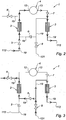
figure 2 est une vue schématique du premier réseau explicitant une circulation du premier fluide au travers du réseau en cas de forte vitesse d'un avion, - la
figure 3 est une vue schématique du premier réseau explicitant une circulation du premier fluide au travers du réseau en cas de faible vitesse de l'avion, - la
figure 4 est une vue schématique d'un second réseau de circulation du premier fluide selon un second mode de réalisation de la présente invention, - la
figure 5 est une vue partielle en perspective d'une lèvre d'entrée d'air d'une nacelle d'avion dans laquelle est installée le second réseau, - la
figure 6 est une vue schématique du second réseau explicitant une circulation du premier fluide au travers du réseau en cas de forte vitesse de l'avion, - la
figure 7 est une vue schématique du second réseau explicitant une circulation du premier fluide au travers du réseau en cas de faible vitesse de l'avion, - la
figure 8 est une vue schématique du second réseau explicitant une circulation du premier fluide au travers du réseau en mode de dégivrage de la lèvre d'entrée d'air, - la
figure 9 est une vue schématique d'un troisième réseau de circulation du premier fluide selon un troisième mode de réalisation de la présente invention, - la
figure 10 est une vue schématique de la lèvre d'entrée d'air équipée d'un quatrième réseau de circulation du premier fluide selon un quatrième mode de réalisation de la présente invention, - la
figure 11 est une vue schématique du quatrième réseau de circulation du premier fluide selon le quatrième mode de réalisation de la présente invention, - la
figure 12 est une vue schématique du quatrième réseau explicitant une circulation du premier fluide au travers du réseau en cas de forte vitesse de l'avion, - la
figure 13 est une vue schématique du quatrième réseau explicitant une circulation du premier fluide au travers du réseau en cas de faible vitesse de l'avion, - la
figure 14 est une vue schématique du quatrième réseau explicitant une circulation du premier fluide au travers du réseau en mode de dégivrage de la lèvre d'entrée d'air, - la
figure 15 est une vue schématique du quatrième réseau explicitant le fonctionnement du réseau en cas de panne d'un ou plusieurs éléments de commande de la circulation du premier fluide au travers du réseau.
- the
figure 1 is a schematic view of a first circulation network of the first fluid according to a first embodiment of the present invention, - the
figure 2 is a schematic view of the first network explaining a circulation of the first fluid through the network in case of high speed of an aircraft, - the
figure 3 is a schematic view of the first network explaining a circulation of the first fluid through the network in case of low speed of the aircraft, - the
figure 4 is a schematic view of a second circulation network of the first fluid according to a second embodiment of the present invention, - the
figure 5 is a partial perspective view of an air intake lip of an aircraft nacelle in which the second network is installed, - the
figure 6 is a schematic view of the second network explaining a circulation of the first fluid through the network in case of high speed of the aircraft, - the
figure 7 is a schematic view of the second network explaining a circulation of the first fluid through the network in case of low speed of the aircraft, - the
figure 8 is a schematic view of the second network explaining a circulation of the first fluid through the network in defrosting mode of the air intake lip, - the
figure 9 is a schematic view of a third circulation network of the first fluid according to a third embodiment of the present invention, - the
figure 10 is a schematic view of the air intake lip equipped with a fourth circulation network of the first fluid according to a fourth embodiment of the present invention, - the
figure 11 is a schematic view of the fourth circulation network of the first fluid according to the fourth embodiment of the present invention, - the
figure 12 is a schematic view of the fourth network explaining a circulation of the first fluid through the network in case of high speed of the aircraft, - the
figure 13 is a schematic view of the fourth network explaining a circulation of the first fluid through the network in case of low speed of the aircraft, - the
figure 14 is a schematic view of the fourth network explaining a circulation of the first fluid through the network in defrosting mode of the air intake lip, - the
figure 15 is a schematic view of the fourth network explaining the operation of the network in case of failure of one or more control elements of the circulation of the first fluid through the network.
Dans tous les modes de réalisation décrits ci-après, le premier fluide est sensiblement constitué d'air, et le second fluide est sensiblement constitué d'une huile moteur choisie parmi celles couramment utilisées dans le domaine aéronautique. Toutefois, le premier fluide et le second fluide peuvent être constitués sensiblement par toutes autres matières qui conviendraient à leur utilisation conjointe dans le domaine aéronautique.In all the embodiments described below, the first fluid is substantially composed of air, and the second fluid consists substantially of a motor oil chosen from those commonly used in the aeronautical field. However, the first fluid and the second fluid may consist substantially of any other material that would be suitable for their joint use in the aeronautical field.
Dans tous les modes de réalisation décrits ci-après, et dans un souci de simplification, les canalisations reliant les différents éléments des différents réseaux 1 de circulation d'air sont appelées « canalisation 19 ».In all the embodiments described below, and for the sake of simplification, the pipes connecting the different elements of the
Dans tous les modes de réalisation décrits ci-après, on entend par « traverser le réseau » traverser tout ou partie d'un réseau 1, on entend par vanne commandée une vanne tenant un rôle de robinet-vanne, actionneur ou non, on entend par écope dynamique une écope de préférence équipée d'au moins une vanne de régulation.In all the embodiments described below, the term "cross the network" through all or part of a
En référence à la
Le premier réseau 1 est compris dans une nacelle 100 d'avion.The
La nacelle 100 comprend une paroi aérodynamique externe 110 comprenant une lèvre d'entrée d'air 111 amont, une paroi aérodynamique interne 120, la lèvre d'entrée d'air 111 reliant en amont les deux parois aérodynamiques externe 110 et interne 120.The
Le premier réseau 1 de circulation d'air pour le refroidissement d'huile moteur comprend deux échangeurs de chaleur air / huile (respectivement 2 et 3), et un échangeur air / air 4.The first
Le premier réseau 1 comprend des vannes anti-retour n'autorisant la circulation de l'air que dans un sens (respectivement 5, 6, et 7), des vannes commandées (respectivement 8 et 9), et la canalisation 19.Les vannes 5, 6, 7, 8 et 9 servent à contrôler la circulation de l'air dans le premier réseau 1.The
L'échangeur air / air 4 est un échangeur surfacique présentant une surface d'échange 10 réalisée à partir de la paroi aérodynamique externe 110 de la nacelle 100. L'échangeur air / air 4 comprend aussi un espace confiné 11, comprenant une entrée d'air 12 et une sortie d'air 13 du premier fluide, enfermé par la surface d'échange 10 et une paroi périphérique 14. L'échangeur air / air 4 comprend aussi une paroi intermédiaire 15 divisant l'espace confiné 11 en deux volumes de telle manière que son plan moyen soit sensiblement parallèle au plan moyen de la surface d'échange 10, et que l'un des volumes, dit volume supérieur 16, est délimité par la surface d'échange 10, la paroi périphérique 14 et la paroi intermédiaire 15, et l'autre des volumes, dit volume inférieur 17, est délimité par la paroi périphérique 14 et la paroi intermédiaire 15. La paroi intermédiaire 15 est percée d'une pluralité d'orifices 18. Le volume inférieur 17 communique avec l'entrée d'air 12, et le volume supérieur 16 communique avec la sortie d'air 13.The air /
L'échangeur air / air 4 peut aussi ne comprendre qu'une surface d'échange 10 au contact de laquelle vient une canalisation 19 du premier circuit 1 afin de refroidir l'air circulant dans le premier réseau 1 et sortant de l'échangeur air / huile 2 afin de pénétrer refroidi dans l'échangeur air / huile 3.The air /
La paroi aérodynamique externe 110 de la nacelle comprend une écope dynamique 112 de prélèvement d'air venant de l'extérieur de la nacelle ainsi qu'un orifice de sortie 113 d'air réchauffé hors de la nacelle 100 après avoir traversé le premier réseau 1.The outer
La paroi aérodynamique interne 120 comprend un orifice 121 de prélèvement d'air froid venant d'une soufflante 130 de l'aéronef à l'aide de la vanne commandée 8 du premier réseau 1, dit prélèvement soufflante 121.The internal
En référence à la
Les vannes commandées 8 et 9 sont fermées ainsi que la vanne anti-retour 6.The controlled
L'air pénètre par l'écope dynamique 112 de la paroi aérodynamique externe 110 dans la canalisation 19 du premier réseau 1. L'air prélevé par l'écope dynamique 112 vient de l'extérieur de la nacelle 100, il est donc froid.The air enters through the
Puis l'air passe par la vanne anti-retour 5 du premier réseau 1, la canalisation 19, l'échangeur air / huile 2 où il récupère la chaleur de l'huile, il pénètre ensuite dans l'échangeur air / air 4 par l'entrée d'air 12.Then the air passes through the
Dans l'échangeur air / air 4, l'air circule depuis l'entrée d'air 12 dans le volume inférieur 17 et traverse la paroi intermédiaire 15 par les orifices 18 pour atteindre le volume supérieur 16. Dans le volume supérieur 16 l'air, en circulant, entre en contact avec la surface d'échange 10 qui est une surface d'échange thermique par impact ou circulation simple des fluides. A ce stade, l'air à l'extérieur de la nacelle 100 est froid et refroidit donc la surface d'échange 10, qui elle-même refroidit l'air se trouvant dans le volume supérieur 16.In the air /
Puis l'air refroidi circulant dans le volume supérieur 16 pénètre dans la canalisation 19 par la sortie d'air 13 cette fois, et passe successivement par la vanne anti-retour 7, l'échangeur air / huile 3 où il récupère la chaleur de l'huile pour enfin sortir de la nacelle 100 par l'orifice de sortie 113 de la nacelle 100.Then the cooled air flowing in the
En référence à la
Dans ce cas, l'air est prélevé dans la soufflante 130 de la nacelle 100, il est donc aussi froid.In this case, the air is taken from the
Les vannes anti-retour 5 et 7 sont fermées.The
L'air pénètre par le prélèvement soufflante 121 de la paroi aérodynamique interne 120 dans la canalisation 19 du premier réseau 1, et passe par la vanne commandée 8, électrique ou pneumatique. A ce stade, la canalisation 19 se dédouble pour diviser le débit d'air en deux, une première partie de l'air ayant passé la vanne commandée se dirige alors vers l'échangeur air / huile 2 tandis qu'une deuxième partie se dirige vers l'échangeur air / huile 3.The air enters through the
Avant d'atteindre l'échangeur air / huile 2, la première partie de l'air passe par une vanne anti-retour 6, une fois que l'air a pénétré dans l'échangeur air / huile 2, il se dirige vers l'orifice de sortie 113 de la paroi aérodynamique externe 110 après passage par la vanne commandée 9.Before reaching the air /
La deuxième partie de l'air pénètre directement dans l'échangeur air / huile 3 pour ensuite se diriger vers l'orifice de sortie 113.The second part of the air enters directly into the air /
En référence à la
Dans ce mode de réalisation, la lèvre d'entrée d'air 111 joue le rôle d'échangeur air / air 4.In this embodiment, the
Le second réseau 1 comprend cinq vannes commandées 8, 9, 20, 21 et 22 ; trois vannes anti-retour 5, 6 et 23 ; deux échangeurs air / huile 2 et 3 ; un échangeur air / air 4.The
La nacelle 100 comprend un moyen de prélèvement d'air chaud venant d'un compresseur de l'aéronef, dit prélèvement compresseur 122, de manière à permettre l'alimentation en air chaud de la lèvre d'entrée d'air 111.Le prélèvement compresseur 122 est connecté à la vanne commandée 21 qui elle-même est directement connectée à l'échangeur air / air 4 via l'orifice 13.The
L'échangeur air / air 4 comprend trois orifices d'entrée et de sortie d'air, un orifice de sortie 24 d'air donnant directement sur l'orifice de sortie 113 de la nacelle 100 via la vanne commandée 22, un autre orifice est l'orifice 13 donnant sur l'échangeur air / huile 3, servant alors de sortie d'air, et sur le prélèvement compresseur 122 via la vanne commandée 21, servant alors d'entrée d'air chaud venant du compresseur (non représenté). Le troisième orifice est l'entrée d'air 12 d'air venant de l'échangeur air / huile 2.The air /
L'échangeur air / air 4 fonctionne sensiblement de la même manière que celui décrit dans le mode de réalisation précédent (premier réseau 1).The air /
En référence à la
La lèvre d'entrée d'air 111 fait office d'échangeur air / air 4. L'air y pénètre par l'orifice 13 ou par l'entrée d'air 12 et en ressort par l'orifice de sortie 24 ou par l'orifice 13 selon le mode de fonctionnement du second réseau 1.The
En référence à la
Les vannes commandées 8, 9, 21 et 22 sont fermées, ainsi que la vanne anti-retour 6.The controlled
L'air pénètre par l'écope dynamique 112 dans la canalisation 19 ; venant de l'extérieur de la nacelle 100, l'air est donc froid.The air enters through the
Puis l'air passe successivement par la vanne anti-retour 5, l'échangeur air / huile 2 où il se réchauffe de la chaleur émise par l'huile moteur, la vanne anti-retour 23, l'entrée d'air 12 l'échangeur air / air 4 où il se refroidit, l'orifice 13, la vanne commandée 20, l'échangeur air / huile 3 où il se réchauffe de la chaleur émise par l'huile moteur, et l'orifice de sortie 113 de la paroi aérodynamique externe 110 de la nacelle 100.Then the air successively passes through the
En référence à la
Les vannes commandées 9, 20 et 21 sont fermées ainsi que la vanne anti-retour 5.The controlled
L'air pénètre par le prélèvement soufflante 121 dans la canalisation 19, venant de la soufflante, l'air est donc froid, puis il passe par la vanne commandée 8.The air enters through the
A ce stade, la canalisation 19 se dédouble pour diviser le débit d'air en deux, une première partie de l'air ayant passé la vanne commandée 8 se dirige alors vers l'échangeur air / huile 2 tandis qu'une deuxième partie se dirige vers l'échangeur air / huile 3.At this stage, the
Avant d'atteindre l'échangeur air / huile 2, la première partie de l'air passe par la vanne anti-retour 6, une fois que l'air a pénétré dans l'échangeur air / huile 2, il se réchauffe et passe ensuite par la vanne anti-retour 23, pénètre dans l'échangeur air / air 4 par l'entrée d'air 12 pour être immédiatement évacué par l'orifice de sortie 24 vers l'orifice de sortie 113 de la paroi aérodynamique externe 110 en passant par la vanne commandée 22.Before reaching the air /
La deuxième partie de l'air pénètre directement dans l'échangeur air / huile 3, s'y réchauffe, pour ensuite être évacué par l'orifice de sortie 113.The second part of the air enters directly into the air /
En référence à la
La vanne commandée 20 est fermée ainsi que les vannes anti-retour 5 et 23.The controlled
De l'air pénètre par le prélèvement soufflante 121 dans la canalisation 19, venant de la soufflante, l'air est donc froid, puis il passe par la vanne commandée 8.Air enters through the
A ce stade, la canalisation 19 se dédouble pour diviser le débit d'air en deux, une première partie de l'air ayant passé la vanne commandée 8 se dirige alors vers l'échangeur air / huile 2 tandis qu'une deuxième partie se dirige vers l'échangeur air / huile 3.At this stage, the
Avant d'atteindre l'échangeur air / huile 2, la première partie de l'air passe par une vanne anti-retour 6, une fois que l'air a pénétré dans l'échangeur air / huile 2, il se réchauffe et est ensuite évacué vers l'orifice de sortie 113 en passant par la vanne commandée 9.Before reaching the air /
La deuxième partie de l'air pénètre directement dans l'échangeur air / huile 3, s'y réchauffe, pour ensuite évacué par l'orifice de sortie 113.The second part of the air enters directly into the air /
Ainsi, l'huile moteur passant par les échangeurs air / huile 2 et 3 est refroidie.Thus, the engine oil passing through the air /
En parallèle, de l'air pénètre par le prélèvement compresseur 122 dans la canalisation 19 du second réseau 1 ; venant du compresseur, l'air est donc chaud et sous haute pression. Cet air passe ensuite par la vanne commandée 21 pour ensuite se diriger directement vers l'orifice 13 et être injecté sous haute pression dans la lèvre d'entrée d'air 111 faisant office d'échangeur air / air 4. L'air ainsi injecté sous haute pression effectue plusieurs révolutions le long de la circonférence de la lèvre d'entrée d'air 111 pour dégivrer l'ensemble de la lèvre d'entrée d'air 111, puis il est évacué vers l'orifice de sortie 113 en passant par la vanne commandée 22.In parallel, air enters via the
En référence à la
Le troisième réseau 1 présente la même structure que le second réseau (
En référence à la
L'échangeur air / air 4 de la
L'échangeur air / air 4 comporte une différence par rapport à celui de la
En référence à la
Le quatrième réseau 1 comprend trois vannes commandées 8, 21 et 28, trois vannes anti-retour 5, 6 et 30, une vanne deux positions 27, deux échangeurs air / huile 2 et 3, et deux échangeurs air / air 4 et 29.The
La nacelle 100 comprend le prélèvement compresseur 122 connecté à la vanne commandée 21 elle-même connectée à l'entrée d'air 12 de l'échangeur air / air 4, le prélèvement soufflante 121 connecté à la vanne commandée 8, l'écope dynamique 112 et l'orifice de sortie 113.The
Le collecteur 31 étant compris dans l'échangeur air / air, il n'est pas représenté ici, mais il donne sur la sortie d'air 13 qui elle-même donne sur l'orifice de sortie 113 de la nacelle.The manifold 31 is included in the air / air exchanger, it is not shown here, but it gives on the
La vanne deux positions 27 permet d'orienter le flux d'air venant des échangeurs air / huile 2 et 3 alternativement vers deux directions différentes, l'une donnant directement sur l'orifice de sortie 113 de la nacelle 100, l'autre donnant directement sur l'échangeur air / air 4.The two-
L'échangeur air / air 29 peut être installé dans la nacelle 100 de la même manière qu'explicitée sur la
En référence à la
Les vannes commandées 8, 21 et 28 sont fermées, la vanne anti-retour 6 est fermée, et la vanne deux positions 27 oriente le flux d'air directement vers l'orifice de sortie 113.The controlled
L'air pénètre dans le quatrième réseau 1 par l'écope dynamique 112 de la nacelle 100, puis il passe successivement par la vanne anti-retour 5, l'échangeur air / huile 2 où il se réchauffe, l'échangeur air / air 29 où il se refroidit, la vanne anti-retour 30, l'échangeur air / huile 3 où il se réchauffe, puis il se dirige directement vers l'orifice de sortie 113 en passant par la vanne deux positions 27 positionnée à cet effet.The air enters the
Ainsi, l'huile moteur passant par les échangeurs air / huile 2 et 3 est refroidie.Thus, the engine oil passing through the air /
Ce fonctionnement du quatrième réseau 1 au regard de la circulation de l'air en son sein est sensiblement similaire à celui du premier réseau explicité dans la
En référence à la
Dans ce cas, la vanne commandée 21 est fermée, les vannes anti-retour 5 et 30 sont fermées, et la vanne deux positions 27 oriente le flux d'air directement vers l'orifice de sortie 113.In this case, the controlled
L'air pénètre par le prélèvement soufflante 121 dans la canalisation 19, venant de la soufflante, l'air est donc froid, puis il passe par la vanne commandée 8.The air enters through the
A ce stade, la canalisation 19 se dédouble pour diviser le débit d'air en deux, une première partie de l'air ayant passé la vanne commandée 8 se dirige alors vers l'échangeur air / huile 2 tandis qu'une deuxième partie se dirige vers l'échangeur air / huile 3.At this stage, the
Avant d'atteindre l'échangeur air / huile 2, la première partie de l'air passe par la vanne anti-retour 6, une fois que l'air a pénétré dans l'échangeur air / huile 2, il se réchauffe et passe ensuite par la vanne commandée 28 pour être immédiatement évacué via la vanne deux positions 27 vers l'orifice de sortie 113.Before reaching the air /
La deuxième partie de l'air pénètre directement dans l'échangeur air / huile 3, s'y réchauffe, pour ensuite être évacué par l'orifice de sortie 113 via la vanne deux positions 27.The second part of the air enters directly into the air /
Ainsi, l'huile moteur passant par les échangeurs air / huile 2 et 3 est refroidie.Thus, the engine oil passing through the air /
En référence à la
Les vannes anti-retour 5 et 30 sont fermées, la vanne deux positions 27 oriente le flux d'air directement vers l'échangeur air / air 4.The
L'air pénètre par le prélèvement soufflante 121 dans la canalisation 19, venant de la soufflante, l'air est donc froid, puis il passe par la vanne commandée 8.The air enters through the
A ce stade, la canalisation 19 se dédouble pour diviser le débit d'air en deux, une première partie de l'air ayant passé la vanne commandée 8 se dirige alors vers l'échangeur air / huile 2 tandis qu'une deuxième partie se dirige vers l'échangeur air / huile 3.At this stage, the
Avant d'atteindre l'échangeur air / huile 2, la première partie de l'air passe par la vanne anti-retour 6, une fois que l'air a pénétré dans l'échangeur air / huile 2, il se réchauffe et passe ensuite par la vanne commandée 28 pour être immédiatement dirigé via la vanne deux positions 27 vers l'échangeur air / air 4.Before reaching the air /
La deuxième partie de l'air pénètre directement dans l'échangeur air / huile 3, s'y réchauffe, pour ensuite être dirigé vers l'échangeur air / air 4 via la vanne deux positions 27.The second part of the air enters directly into the air /
Ainsi, l'huile moteur passant par les échangeurs air / huile 2 et 3 est refroidie.Thus, the engine oil passing through the air /
En parallèle, de l'air pénètre par le prélèvement compresseur 122 dans la canalisation 19 du quatrième réseau 1 ; venant du compresseur, l'air est donc chaud et sous haute pression. Cet air passe ensuite par la vanne commandée 21 pour ensuite se diriger directement vers l'entrée d'air 12.In parallel, air enters through the
A ce stade, l'air provenant du compresseur et celui provenant des échangeurs air / huile 2 et 3 se rejoignent dans la canalisation 19, le nouveau débit d'air formé atteint alors l'entrée d'air 12. L'air est ensuite injecté sous haute pression dans la lèvre d'entrée d'air 111 faisant office d'échangeur air / air 4. L'air ainsi injecté sous haute pression effectue alors plusieurs révolutions le long de la circonférence de la lèvre d'entrée d'air 111 pour dégivrer l'ensemble de la lèvre d'entrée d'air 111, puis il est évacué vers l'orifice de sortie 113 en passant par le collecteur 31 puis la sortie d'air 13.At this stage, the air coming from the compressor and that coming from the air /
En référence à la
Dans ce cas, on force l'ouverture des vannes commandées 8, 21 et 28, et on force la vanne deux positions 27 de manière à ce qu'elle dirige le flux d'air passant par elle directement vers l'orifice de sortie 113 de la nacelle 100. La vanne anti-retour 6 est ouverte tandis que les vannes anti-retour 5 et 30 sont fermées.In this case, the controlled
Dans ce cas, le flux d'air provenant de la soufflante par le prélèvement soufflante 121 suit le même parcours que celui explicité dans la description de la
Il est aussi possible d'envisager un quatrième réseau 1 dans lequel on a retiré le prélèvement compresseur. Ce type de réseau est mis en oeuvre quand l'air ayant traversé les échangeurs air / huile 2 et 3 est à une température suffisante pour dégivrer la lèvre d'entrée d'air 111, qui joue aussi le rôle d'échangeur air / air 4.It is also possible to envisage a
Dans tous les modes de réalisation décrits précédemment, l'orifice de sortie 113 peut être placé au niveau de la paroi aérodynamique interne 120 de la nacelle 100.In all the embodiments described above, the
Dans les modes de réalisation où l'échangeur air / air 4 est installé dans la lèvre d'entrée d'air 111, l'air introduit dans l'échangeur air / air 4 effectue au moins une révolution le long de la circonférence de la lèvre d'entrée d'air 111 pour dégivrer l'ensemble de la lèvre d'entrée d'air 111 avant d'être évacué de l'échangeur air / air 4.In embodiments where the air /
Les modes de réalisation décrits précédemment permettent de réduire de manière non négligeable la consommation globale de l'aéronef de 0,25% à 0,4% par rapport à un refroidissement par prélèvement uniquement dans la veine secondaire. Dans les cas où ils permettent de dégivrer la lèvre d'entrée d'air, ils permettent alors de réduire la température vue par la lèvre d'entrée d'air, réduisant ainsi les problèmes récurrents de fatigue, et par la zone amont de la paroi aérodynamique externe, la température de la dite zone ne dépassant alors pas la température maximale de l'huile d'une turbomachine, typiquement 180°C, permettant de réaliser la cloison avant de l'entrée d'air en aluminium plutôt qu'en titane.The embodiments described above make it possible to reduce in a significant way the overall consumption of the aircraft from 0.25% to 0.4% compared to a sampling cooling only in the secondary vein. In cases where they allow to deice the air intake lip, they then reduce the temperature seen by the air intake lip, thus reducing the recurring problems of fatigue, and by the upstream zone of the air outer aerodynamic wall, the temperature of said zone not exceeding the maximum temperature of the oil of a turbomachine, typically 180 ° C, to achieve the wall before the aluminum air intake rather than titanium.
Bien que l'invention ait été décrite avec des exemples particuliers de réalisation, il est bien évident qu'elle n'y est nullement limitée et qu'elle comprend tous les équivalents techniques des moyens décrits, ainsi que leurs combinaisons si celles-ci entrent dans le cadre de l'invention.Although the invention has been described with particular examples of embodiment, it is obvious that it is not limited thereto and that it includes all the technical equivalents of the means described, and their combinations if they enter in the context of the invention.
Claims (11)
- An aircraft nacelle (100) comprising: an outer aerodynamic wall (110) comprising an upstream air inlet lip (111), an inner aerodynamic wall (120), the air inlet lip (111) connecting upstream both outer (110) and inner (120) aerodynamic walls, a front partition located immediately downstream of the lip and connecting both outer and inner aerodynamic walls, a network (1) for circulating a first coolant of a second fluid comprising at least two air/oil type heat exchangers (2, 3), at least one air/air type exchanger (4) characterized in that the circulating network (1) comprises at least one dynamic scoop (112) for bleeding air coming from outside the nacelle (100), at least one port (121) for bleeding cool air coming from a fan (130) and at least one port (113) for exit of the air out of the nacelle (100).
- The nacelle (100) according to claim 1, characterized in that the air/air type exchanger (4) is located, opposite the path of the first fluid, between the two air/oil type heat exchangers (2, 3).
- The nacelle (100) according to any one of claims 1 or 2, characterized in that the air/air type exchanger (4) is a surface exchanger having an exchange surface (10).
- The nacelle (100) according to claim 3, characterized in that the exchange surface (10) is made from the outer aerodynamic wall (110) of the nacelle (100).
- The nacelle (100) according to any one of the preceding claims 3 or 4, characterized in that the air/air type exchanger (4) comprises an intermediate wall (15) pierced by a plurality of ports (18).
- The nacelle (100) according to any one of the preceding claims, characterized in that the air/air type exchanger (4) has a confined space (11), comprising an inlet (12) and an outlet (13) of the first fluid, enclosed by walls comprising the exchange surface (10) and a peripheral wall (14).
- The nacelle (100) according to any one of the preceding claims, characterized in that the fan bleed supplies each of the air/oil exchangers (2/3).
- The nacelle (100) according to any one of claims 6 or 7, characterized in that the confined space (11) is located in the air inlet lip (111).
- The nacelle (100) according to any one of the preceding claims, characterized in that it comprises at least one controlled means (122) for bleeding hot air coming from a compressor of the aircraft so as to allow supplying the air inlet lip (111) with hot air in the area comprised between the peripheral wall (14) and the intermediate wall (15).
- The nacelle (100) according to any one of the preceding claims, characterized in that it comprises at least one high pressure injector controlled so as to inject hot air coming from the controlled means (122) for bleeding hot air in the air inlet lip (111).
- The nacelle (100) according to any one of the preceding claims, characterized in that the outer aerodynamic wall (110) comprises at least one port (113) for exit of the first heated fluid out of the nacelle (100) after having passed through the network (1).
Applications Claiming Priority (2)
| Application Number | Priority Date | Filing Date | Title |
|---|---|---|---|
| FR1352069A FR3002978B1 (en) | 2013-03-07 | 2013-03-07 | NACELLE EQUIPPED WITH AN INTERMEDIATE EXCHANGER OIL COOLING CIRCUIT |
| PCT/FR2014/050520 WO2014135812A1 (en) | 2013-03-07 | 2014-03-07 | Nacelle equipped with an oil-cooling circuit comprising an intermediate heat exchanger |
Publications (3)
| Publication Number | Publication Date |
|---|---|
| EP2964906A1 EP2964906A1 (en) | 2016-01-13 |
| EP2964906B1 true EP2964906B1 (en) | 2017-01-04 |
| EP2964906B8 EP2964906B8 (en) | 2017-03-22 |
Family
ID=48289398
Family Applications (1)
| Application Number | Title | Priority Date | Filing Date |
|---|---|---|---|
| EP14715041.1A Active EP2964906B8 (en) | 2013-03-07 | 2014-03-07 | Nacelle equipped with an oil-cooling circuit comprising an intermediate heat exchanger |
Country Status (6)
| Country | Link |
|---|---|
| US (1) | US10087841B2 (en) |
| EP (1) | EP2964906B8 (en) |
| CA (1) | CA2900896A1 (en) |
| FR (1) | FR3002978B1 (en) |
| RU (1) | RU2015140420A (en) |
| WO (1) | WO2014135812A1 (en) |
Families Citing this family (9)
| Publication number | Priority date | Publication date | Assignee | Title |
|---|---|---|---|---|
| US9765694B2 (en) * | 2012-08-07 | 2017-09-19 | Unison Industries, Llc | Gas turbine engine heat exchangers and methods of assembling the same |
| EP3018304B1 (en) * | 2014-11-06 | 2020-10-14 | United Technologies Corporation | Thermal management system for a gas turbine engine |
| FR3054856B1 (en) * | 2016-08-03 | 2018-09-07 | Airbus Operations Sas | TURBOMACHINE COMPRISING A THERMAL MANAGEMENT SYSTEM |
| FR3072421B1 (en) * | 2017-10-18 | 2019-09-27 | Airbus Operations | AIR INLET LIGHT OF AN AIRCRAFT ENGINE COMPRISING A DEFROSTING SYSTEM |
| US11292604B2 (en) * | 2017-10-23 | 2022-04-05 | Pratt & Whitney Canada Corp. | Integrated heat management for hybrid propulsion |
| US11035295B2 (en) * | 2018-04-18 | 2021-06-15 | Lockheed Martin Corporation | Engine nacelle heat exchanger |
| GB201811040D0 (en) * | 2018-07-05 | 2018-08-22 | Rolls Royce Plc | Cooling |
| FR3094754B1 (en) | 2019-04-03 | 2021-03-12 | Safran Nacelles | Aircraft nacelle comprising at least one heat exchanger |
| US11577843B2 (en) * | 2019-11-05 | 2023-02-14 | Rohr, Inc. | Thermal anti-icing system with non-circular piccolo tube |
Family Cites Families (4)
| Publication number | Priority date | Publication date | Assignee | Title |
|---|---|---|---|---|
| US4782658A (en) * | 1987-05-07 | 1988-11-08 | Rolls-Royce Plc | Deicing of a geared gas turbine engine |
| FR2771776B1 (en) * | 1997-12-02 | 2000-01-28 | Aerospatiale | HOT AIR DISCHARGE DEVICE FOR REACTION ENGINE AIR INTAKE COVER WITH DEFROSTING CIRCUIT |
| GB0311663D0 (en) * | 2003-05-21 | 2003-06-25 | Rolls Royce Plc | Aeroengine intake |
| FR2958974B1 (en) * | 2010-04-16 | 2016-06-10 | Snecma | GAS TURBINE ENGINE PROVIDED WITH AN AIR-OIL HEAT EXCHANGER IN ITS AIR INLET HANDLE |
-
2013
- 2013-03-07 FR FR1352069A patent/FR3002978B1/en active Active
-
2014
- 2014-03-07 WO PCT/FR2014/050520 patent/WO2014135812A1/en active Application Filing
- 2014-03-07 EP EP14715041.1A patent/EP2964906B8/en active Active
- 2014-03-07 RU RU2015140420A patent/RU2015140420A/en not_active Application Discontinuation
- 2014-03-07 CA CA2900896A patent/CA2900896A1/en not_active Abandoned
-
2015
- 2015-09-04 US US14/846,129 patent/US10087841B2/en active Active
Non-Patent Citations (1)
| Title |
|---|
| None * |
Also Published As
| Publication number | Publication date |
|---|---|
| FR3002978B1 (en) | 2016-12-30 |
| US10087841B2 (en) | 2018-10-02 |
| CA2900896A1 (en) | 2014-09-12 |
| WO2014135812A1 (en) | 2014-09-12 |
| EP2964906B8 (en) | 2017-03-22 |
| EP2964906A1 (en) | 2016-01-13 |
| US20150377132A1 (en) | 2015-12-31 |
| FR3002978A1 (en) | 2014-09-12 |
| RU2015140420A (en) | 2017-04-10 |
Similar Documents
| Publication | Publication Date | Title |
|---|---|---|
| EP2964906B1 (en) | Nacelle equipped with an oil-cooling circuit comprising an intermediate heat exchanger | |
| EP2819921B1 (en) | Engine nacelle comprising a heat exchanger | |
| EP3013689B1 (en) | De-icing and conditioning device for an aircraft | |
| CA2904311C (en) | Cooling device for a turbo engine of an aircraft nacelle | |
| EP2472067B1 (en) | Integration of a surface heat exchanger with controlled air flow in an airplane engine | |
| EP1018468B1 (en) | Turbomachine with a reduction gear equipped with a cooling device | |
| EP3224462B1 (en) | Cooling device for a turbomachine supplied by a discharge circuit | |
| FR3027624A1 (en) | CIRCUIT FOR DEFROSTING AN AIR INLET LIP FROM A PROPELLANT AIRCRAFT ASSEMBLY | |
| FR3001253A1 (en) | CONTROLLED OIL COOLING SYSTEM OF A TURBOJET ENGINE WITH DEFROSTING THE NACELLE | |
| FR2734320A1 (en) | DEVICE FOR PREDICTING AND COOLING HOT AIR AT AN AIRCRAFT ENGINE | |
| EP3487764B1 (en) | Turbine engine nacelle comprising a cooling device | |
| FR3054856A1 (en) | TURBOMACHINE COMPRISING A THERMAL MANAGEMENT SYSTEM | |
| FR3039134A1 (en) | AIRCRAFT WITH A PROPULSIVE ASSEMBLY COMPRISING A BLOWER AT THE REAR OF THE FUSELAGE | |
| EP3418194A1 (en) | System and method for environmental control of an aircraft cabin and aircraft provided with such a control system | |
| FR3051219A1 (en) | TURBOMACHINE TURBINE, SUCH AS A TURBOREACTOR OR AIRCRAFT TURBOPROPOWER | |
| EP3615780A1 (en) | Aircraft propulsion assembly comprising air-liquid heat exchangers | |
| EP3931089B1 (en) | Air conditioning system for an aircraft cabin, comprising means for reheating the water collected by the water extraction loop | |
| FR3039208A1 (en) | DEFROSTING AN AIR INLET LIP AND COOLING A TURBINE HOUSING OF A PROPELLANT AIRCRAFT ASSEMBLY | |
| EP3521590B1 (en) | System for cooling engine air with two cooling stages and comprising at least one cylindrical heat exchanger | |
| EP3418192B1 (en) | System for recovering thermal energy from a main power-transmission gearbox of an aircraft for heating the passenger compartment of the aircraft | |
| EP3719278A1 (en) | Aircraft nacelle comprising at least one heat exchanger | |
| FR3089204A1 (en) | Air management system especially for air conditioning and defrost pack |
Legal Events
| Date | Code | Title | Description |
|---|---|---|---|
| PUAI | Public reference made under article 153(3) epc to a published international application that has entered the european phase |
Free format text: ORIGINAL CODE: 0009012 |
|
| 17P | Request for examination filed |
Effective date: 20150807 |
|
| AK | Designated contracting states |
Kind code of ref document: A1 Designated state(s): AL AT BE BG CH CY CZ DE DK EE ES FI FR GB GR HR HU IE IS IT LI LT LU LV MC MK MT NL NO PL PT RO RS SE SI SK SM TR |
|
| AX | Request for extension of the european patent |
Extension state: BA ME |
|
| DAX | Request for extension of the european patent (deleted) | ||
| REG | Reference to a national code |
Ref country code: DE Ref legal event code: R079 Ref document number: 602014006059 Country of ref document: DE Free format text: PREVIOUS MAIN CLASS: F01D0025120000 Ipc: F01D0025240000 |
|
| GRAP | Despatch of communication of intention to grant a patent |
Free format text: ORIGINAL CODE: EPIDOSNIGR1 |
|
| RIC1 | Information provided on ipc code assigned before grant |
Ipc: F02C 7/14 20060101ALI20160628BHEP Ipc: B64D 33/02 20060101ALI20160628BHEP Ipc: F01D 25/24 20060101AFI20160628BHEP Ipc: F01D 25/12 20060101ALI20160628BHEP |
|
| INTG | Intention to grant announced |
Effective date: 20160801 |
|
| GRAS | Grant fee paid |
Free format text: ORIGINAL CODE: EPIDOSNIGR3 |
|
| GRAA | (expected) grant |
Free format text: ORIGINAL CODE: 0009210 |
|
| AK | Designated contracting states |
Kind code of ref document: B1 Designated state(s): AL AT BE BG CH CY CZ DE DK EE ES FI FR GB GR HR HU IE IS IT LI LT LU LV MC MK MT NL NO PL PT RO RS SE SI SK SM TR |
|
| REG | Reference to a national code |
Ref country code: GB Ref legal event code: FG4D Free format text: NOT ENGLISH |
|
| REG | Reference to a national code |
Ref country code: CH Ref legal event code: EP |
|
| REG | Reference to a national code |
Ref country code: AT Ref legal event code: REF Ref document number: 859446 Country of ref document: AT Kind code of ref document: T Effective date: 20170115 |
|
| RAP2 | Party data changed (patent owner data changed or rights of a patent transferred) |
Owner name: SAFRAN NACELLES |
|
| REG | Reference to a national code |
Ref country code: IE Ref legal event code: FG4D Free format text: LANGUAGE OF EP DOCUMENT: FRENCH |
|
| REG | Reference to a national code |
Ref country code: DE Ref legal event code: R096 Ref document number: 602014006059 Country of ref document: DE Ref country code: FR Ref legal event code: PLFP Year of fee payment: 4 |
|
| REG | Reference to a national code |
Ref country code: LT Ref legal event code: MG4D Ref country code: NL Ref legal event code: MP Effective date: 20170104 |
|
| REG | Reference to a national code |
Ref country code: AT Ref legal event code: MK05 Ref document number: 859446 Country of ref document: AT Kind code of ref document: T Effective date: 20170104 |
|
| PG25 | Lapsed in a contracting state [announced via postgrant information from national office to epo] |
Ref country code: NL Free format text: LAPSE BECAUSE OF FAILURE TO SUBMIT A TRANSLATION OF THE DESCRIPTION OR TO PAY THE FEE WITHIN THE PRESCRIBED TIME-LIMIT Effective date: 20170104 |
|
| PG25 | Lapsed in a contracting state [announced via postgrant information from national office to epo] |
Ref country code: LT Free format text: LAPSE BECAUSE OF FAILURE TO SUBMIT A TRANSLATION OF THE DESCRIPTION OR TO PAY THE FEE WITHIN THE PRESCRIBED TIME-LIMIT Effective date: 20170104 Ref country code: HR Free format text: LAPSE BECAUSE OF FAILURE TO SUBMIT A TRANSLATION OF THE DESCRIPTION OR TO PAY THE FEE WITHIN THE PRESCRIBED TIME-LIMIT Effective date: 20170104 Ref country code: GR Free format text: LAPSE BECAUSE OF FAILURE TO SUBMIT A TRANSLATION OF THE DESCRIPTION OR TO PAY THE FEE WITHIN THE PRESCRIBED TIME-LIMIT Effective date: 20170405 Ref country code: NO Free format text: LAPSE BECAUSE OF FAILURE TO SUBMIT A TRANSLATION OF THE DESCRIPTION OR TO PAY THE FEE WITHIN THE PRESCRIBED TIME-LIMIT Effective date: 20170404 Ref country code: FI Free format text: LAPSE BECAUSE OF FAILURE TO SUBMIT A TRANSLATION OF THE DESCRIPTION OR TO PAY THE FEE WITHIN THE PRESCRIBED TIME-LIMIT Effective date: 20170104 Ref country code: IS Free format text: LAPSE BECAUSE OF FAILURE TO SUBMIT A TRANSLATION OF THE DESCRIPTION OR TO PAY THE FEE WITHIN THE PRESCRIBED TIME-LIMIT Effective date: 20170504 |
|
| PG25 | Lapsed in a contracting state [announced via postgrant information from national office to epo] |
Ref country code: PL Free format text: LAPSE BECAUSE OF FAILURE TO SUBMIT A TRANSLATION OF THE DESCRIPTION OR TO PAY THE FEE WITHIN THE PRESCRIBED TIME-LIMIT Effective date: 20170104 Ref country code: BG Free format text: LAPSE BECAUSE OF FAILURE TO SUBMIT A TRANSLATION OF THE DESCRIPTION OR TO PAY THE FEE WITHIN THE PRESCRIBED TIME-LIMIT Effective date: 20170404 Ref country code: SE Free format text: LAPSE BECAUSE OF FAILURE TO SUBMIT A TRANSLATION OF THE DESCRIPTION OR TO PAY THE FEE WITHIN THE PRESCRIBED TIME-LIMIT Effective date: 20170104 Ref country code: PT Free format text: LAPSE BECAUSE OF FAILURE TO SUBMIT A TRANSLATION OF THE DESCRIPTION OR TO PAY THE FEE WITHIN THE PRESCRIBED TIME-LIMIT Effective date: 20170504 Ref country code: ES Free format text: LAPSE BECAUSE OF FAILURE TO SUBMIT A TRANSLATION OF THE DESCRIPTION OR TO PAY THE FEE WITHIN THE PRESCRIBED TIME-LIMIT Effective date: 20170104 Ref country code: AT Free format text: LAPSE BECAUSE OF FAILURE TO SUBMIT A TRANSLATION OF THE DESCRIPTION OR TO PAY THE FEE WITHIN THE PRESCRIBED TIME-LIMIT Effective date: 20170104 Ref country code: RS Free format text: LAPSE BECAUSE OF FAILURE TO SUBMIT A TRANSLATION OF THE DESCRIPTION OR TO PAY THE FEE WITHIN THE PRESCRIBED TIME-LIMIT Effective date: 20170104 Ref country code: LV Free format text: LAPSE BECAUSE OF FAILURE TO SUBMIT A TRANSLATION OF THE DESCRIPTION OR TO PAY THE FEE WITHIN THE PRESCRIBED TIME-LIMIT Effective date: 20170104 |
|
| REG | Reference to a national code |
Ref country code: DE Ref legal event code: R097 Ref document number: 602014006059 Country of ref document: DE |
|
| PG25 | Lapsed in a contracting state [announced via postgrant information from national office to epo] |
Ref country code: CZ Free format text: LAPSE BECAUSE OF FAILURE TO SUBMIT A TRANSLATION OF THE DESCRIPTION OR TO PAY THE FEE WITHIN THE PRESCRIBED TIME-LIMIT Effective date: 20170104 Ref country code: RO Free format text: LAPSE BECAUSE OF FAILURE TO SUBMIT A TRANSLATION OF THE DESCRIPTION OR TO PAY THE FEE WITHIN THE PRESCRIBED TIME-LIMIT Effective date: 20170104 Ref country code: SK Free format text: LAPSE BECAUSE OF FAILURE TO SUBMIT A TRANSLATION OF THE DESCRIPTION OR TO PAY THE FEE WITHIN THE PRESCRIBED TIME-LIMIT Effective date: 20170104 Ref country code: IT Free format text: LAPSE BECAUSE OF FAILURE TO SUBMIT A TRANSLATION OF THE DESCRIPTION OR TO PAY THE FEE WITHIN THE PRESCRIBED TIME-LIMIT Effective date: 20170104 Ref country code: EE Free format text: LAPSE BECAUSE OF FAILURE TO SUBMIT A TRANSLATION OF THE DESCRIPTION OR TO PAY THE FEE WITHIN THE PRESCRIBED TIME-LIMIT Effective date: 20170104 |
|
| REG | Reference to a national code |
Ref country code: CH Ref legal event code: PL |
|
| PLBE | No opposition filed within time limit |
Free format text: ORIGINAL CODE: 0009261 |
|
| STAA | Information on the status of an ep patent application or granted ep patent |
Free format text: STATUS: NO OPPOSITION FILED WITHIN TIME LIMIT |
|
| PG25 | Lapsed in a contracting state [announced via postgrant information from national office to epo] |
Ref country code: SM Free format text: LAPSE BECAUSE OF FAILURE TO SUBMIT A TRANSLATION OF THE DESCRIPTION OR TO PAY THE FEE WITHIN THE PRESCRIBED TIME-LIMIT Effective date: 20170104 Ref country code: DK Free format text: LAPSE BECAUSE OF FAILURE TO SUBMIT A TRANSLATION OF THE DESCRIPTION OR TO PAY THE FEE WITHIN THE PRESCRIBED TIME-LIMIT Effective date: 20170104 Ref country code: MC Free format text: LAPSE BECAUSE OF FAILURE TO SUBMIT A TRANSLATION OF THE DESCRIPTION OR TO PAY THE FEE WITHIN THE PRESCRIBED TIME-LIMIT Effective date: 20170104 |
|
| REG | Reference to a national code |
Ref country code: IE Ref legal event code: MM4A |
|
| PG25 | Lapsed in a contracting state [announced via postgrant information from national office to epo] |
Ref country code: LU Free format text: LAPSE BECAUSE OF NON-PAYMENT OF DUE FEES Effective date: 20170307 |
|
| REG | Reference to a national code |
Ref country code: FR Ref legal event code: PLFP Year of fee payment: 5 |
|
| PG25 | Lapsed in a contracting state [announced via postgrant information from national office to epo] |
Ref country code: IE Free format text: LAPSE BECAUSE OF NON-PAYMENT OF DUE FEES Effective date: 20170307 Ref country code: SI Free format text: LAPSE BECAUSE OF FAILURE TO SUBMIT A TRANSLATION OF THE DESCRIPTION OR TO PAY THE FEE WITHIN THE PRESCRIBED TIME-LIMIT Effective date: 20170104 Ref country code: LI Free format text: LAPSE BECAUSE OF NON-PAYMENT OF DUE FEES Effective date: 20170331 Ref country code: CH Free format text: LAPSE BECAUSE OF NON-PAYMENT OF DUE FEES Effective date: 20170331 |
|
| REG | Reference to a national code |
Ref country code: BE Ref legal event code: MM Effective date: 20170331 |
|
| PG25 | Lapsed in a contracting state [announced via postgrant information from national office to epo] |
Ref country code: BE Free format text: LAPSE BECAUSE OF NON-PAYMENT OF DUE FEES Effective date: 20170331 |
|
| PG25 | Lapsed in a contracting state [announced via postgrant information from national office to epo] |
Ref country code: MT Free format text: LAPSE BECAUSE OF FAILURE TO SUBMIT A TRANSLATION OF THE DESCRIPTION OR TO PAY THE FEE WITHIN THE PRESCRIBED TIME-LIMIT Effective date: 20170104 |
|
| PG25 | Lapsed in a contracting state [announced via postgrant information from national office to epo] |
Ref country code: HU Free format text: LAPSE BECAUSE OF FAILURE TO SUBMIT A TRANSLATION OF THE DESCRIPTION OR TO PAY THE FEE WITHIN THE PRESCRIBED TIME-LIMIT; INVALID AB INITIO Effective date: 20140307 |
|
| PG25 | Lapsed in a contracting state [announced via postgrant information from national office to epo] |
Ref country code: CY Free format text: LAPSE BECAUSE OF FAILURE TO SUBMIT A TRANSLATION OF THE DESCRIPTION OR TO PAY THE FEE WITHIN THE PRESCRIBED TIME-LIMIT Effective date: 20170104 |
|
| PG25 | Lapsed in a contracting state [announced via postgrant information from national office to epo] |
Ref country code: MK Free format text: LAPSE BECAUSE OF FAILURE TO SUBMIT A TRANSLATION OF THE DESCRIPTION OR TO PAY THE FEE WITHIN THE PRESCRIBED TIME-LIMIT Effective date: 20170104 |
|
| PG25 | Lapsed in a contracting state [announced via postgrant information from national office to epo] |
Ref country code: TR Free format text: LAPSE BECAUSE OF FAILURE TO SUBMIT A TRANSLATION OF THE DESCRIPTION OR TO PAY THE FEE WITHIN THE PRESCRIBED TIME-LIMIT Effective date: 20170104 |
|
| PG25 | Lapsed in a contracting state [announced via postgrant information from national office to epo] |
Ref country code: AL Free format text: LAPSE BECAUSE OF FAILURE TO SUBMIT A TRANSLATION OF THE DESCRIPTION OR TO PAY THE FEE WITHIN THE PRESCRIBED TIME-LIMIT Effective date: 20170104 |
|
| PGFP | Annual fee paid to national office [announced via postgrant information from national office to epo] |
Ref country code: FR Payment date: 20230222 Year of fee payment: 10 |
|
| PGFP | Annual fee paid to national office [announced via postgrant information from national office to epo] |
Ref country code: GB Payment date: 20230221 Year of fee payment: 10 Ref country code: DE Payment date: 20230221 Year of fee payment: 10 |