EP4158172B1 - Einrichtung zur versorgung der brennkammer einer turbomaschine mit kryogenem brennstoff - Google Patents
Einrichtung zur versorgung der brennkammer einer turbomaschine mit kryogenem brennstoff Download PDFInfo
- Publication number
- EP4158172B1 EP4158172B1 EP21734406.8A EP21734406A EP4158172B1 EP 4158172 B1 EP4158172 B1 EP 4158172B1 EP 21734406 A EP21734406 A EP 21734406A EP 4158172 B1 EP4158172 B1 EP 4158172B1
- Authority
- EP
- European Patent Office
- Prior art keywords
- cryogenic fuel
- air
- heat exchanger
- installation
- aircraft
- Prior art date
- Legal status (The legal status is an assumption and is not a legal conclusion. Google has not performed a legal analysis and makes no representation as to the accuracy of the status listed.)
- Active
Links
Images


Classifications
-
- F—MECHANICAL ENGINEERING; LIGHTING; HEATING; WEAPONS; BLASTING
- F02—COMBUSTION ENGINES; HOT-GAS OR COMBUSTION-PRODUCT ENGINE PLANTS
- F02C—GAS-TURBINE PLANTS; AIR INTAKES FOR JET-PROPULSION PLANTS; CONTROLLING FUEL SUPPLY IN AIR-BREATHING JET-PROPULSION PLANTS
- F02C7/00—Features, components parts, details or accessories, not provided for in, or of interest apart form groups F02C1/00 - F02C6/00; Air intakes for jet-propulsion plants
- F02C7/22—Fuel supply systems
- F02C7/224—Heating fuel before feeding to the burner
-
- F—MECHANICAL ENGINEERING; LIGHTING; HEATING; WEAPONS; BLASTING
- F02—COMBUSTION ENGINES; HOT-GAS OR COMBUSTION-PRODUCT ENGINE PLANTS
- F02C—GAS-TURBINE PLANTS; AIR INTAKES FOR JET-PROPULSION PLANTS; CONTROLLING FUEL SUPPLY IN AIR-BREATHING JET-PROPULSION PLANTS
- F02C3/00—Gas-turbine plants characterised by the use of combustion products as the working fluid
- F02C3/20—Gas-turbine plants characterised by the use of combustion products as the working fluid using a special fuel, oxidant, or dilution fluid to generate the combustion products
-
- F—MECHANICAL ENGINEERING; LIGHTING; HEATING; WEAPONS; BLASTING
- F02—COMBUSTION ENGINES; HOT-GAS OR COMBUSTION-PRODUCT ENGINE PLANTS
- F02C—GAS-TURBINE PLANTS; AIR INTAKES FOR JET-PROPULSION PLANTS; CONTROLLING FUEL SUPPLY IN AIR-BREATHING JET-PROPULSION PLANTS
- F02C7/00—Features, components parts, details or accessories, not provided for in, or of interest apart form groups F02C1/00 - F02C6/00; Air intakes for jet-propulsion plants
- F02C7/12—Cooling of plants
- F02C7/14—Cooling of plants of fluids in the plant, e.g. lubricant or fuel
Definitions
- the invention lies in the field of aircraft turbomachines.
- the present invention relates more specifically to an installation for supplying cryogenic fuel to the combustion chamber of a turbomachine of an aircraft and to a turbomachine of an aircraft comprising a primary air stream provided successively with at least one air compressor, a combustion chamber supplied with cryogenic fuel and at least one turbine, this turbomachine being equipped with said installation for supplying cryogenic fuel.
- cryogenic fuel is liquefied natural gas (known by the acronym LNG), which, compared to liquid hydrogen, has the additional advantage of being able to be used at much higher temperatures, since its liquefaction temperature at 1 bar (10 5 Pa) is minus 161°C compared to minus 252°C for liquid hydrogen, which simplifies its use.
- LNG liquefied natural gas
- cryogenic fuel in the combustion chamber not in the gaseous state but in the supercritical fluid state, which is not provided for in the aforementioned state of the art.
- the fuel reaches the supercritical fluid state when it is at a temperature above its critical temperature and at a pressure above its critical pressure.
- cryogenic fuels in liquid form, so that their volume to be transported in the aircraft is acceptable, then to vaporize and/or reheat them to be able to use them in a combustion chamber.
- An aim of the invention is therefore to propose an installation for supplying cryogenic fuel to the combustion chamber of an aircraft turbomachine, which makes it possible to vaporize this liquid cryogenic fuel or to bring it into a supercritical state, in an ecologically and energetically advantageous manner.
- cryogenic fuel/air heat exchanger in the aircraft's air conditioning circuit makes it possible to heat this fuel while reducing the size of the exchangers used in an air conditioning circuit and/or reducing the complexity of the system.
- the invention also relates to a turbomachine of an aircraft comprising a primary air stream provided successively with at least one air compressor, a combustion chamber supplied with cryogenic fuel and at least one turbine.
- this turbomachine comprises an installation for supplying cryogenic fuel to its combustion chamber, as mentioned above.
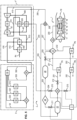
- the air flow circulating in the primary vein 12 successively passes through a low pressure air compressor 14, a high pressure air compressor 15, a combustion chamber 16, a high pressure turbine 17 and a low pressure turbine 18, before being ejected through a primary flow nozzle 19.
- This cryogenic fuel is, for example, liquefied natural gas or liquid hydrogen.
- an injector is used to inject fuel into the combustion chamber 16.
- a first high-pressure pump 22 is arranged on the pipe 200 between the mixing chamber 21 and the combustion chamber 16, so as to bring the cryogenic fuel in the gaseous or supercritical state and coming from the mixing chamber 21, under a high pressure, before its introduction into this combustion chamber 16.
- the air compressor(s) compress the air upstream of the combustion chamber 16, there is therefore a fairly high pressure therein (for example at least 50 bars or 50.10 5 Pa).
- To be able to spray the fuel into the chamber 16 it must therefore be introduced at a pressure higher than that of the chamber 16. This improves the efficiency of the thermodynamic cycle of the turbomachine.
- This heat exchanger 23 is mounted on a pipe 201 connecting said cryogenic fuel tank 20, (preferably a point located at the lower part thereof), to said mixing chamber 21.
- the cryogenic fuel is liquid.
- the exchanger 23 makes it possible to carry out a heat exchange in order, on the one hand, to heat the cryogenic fuel, coming from this tank 20, and on the other hand, to cool the air circulating in the compressor (shown schematically by the flow F1 in the figures).
- the heat exchanger reduces the temperature of the entire flow of the compressor to reduce the work required for compression. This is called intercooling.
- the heat exchange can be carried out at the same time as the compression and the exchanger 23 is then arranged, for example, in the compressor casing. It is also possible to arrange the exchanger 23 between the low pressure compressor 14 and the high pressure compressor 15.
- the exchanger 23 is of the two-phase type and allows the liquid cryogenic fuel to be converted into the gaseous state. This exchanger 23 is then, for example, of the shell and tube type.
- the exchanger 23 makes it possible to pass the cryogenic fuel to a temperature higher than its critical temperature.
- the exchanger 23 is then said to be of the “supercritical” type.
- a second high-pressure pump 24 is arranged on the pipe 201, downstream of the tank 20 and upstream of the heat exchanger 23.
- the pump 24 is chosen to allow the cryogenic fuel to be brought to a pressure higher than its critical pressure.
- the exchanger 25 makes it possible to pass the cryogenic fuel to a temperature higher than its critical temperature.
- the exchanger 25 is then said to be of the “supercritical” type.
- the installation 2 also comprises a cryogenic fuel/air heat exchanger 26 for cooling the blades of the turbine of the turbomachine 1.
- This heat exchanger 26 is mounted on the pipe 202, in series with the heat exchanger 25 and downstream of the latter, relative to the direction of circulation of the cryogenic fuel in the pipe 202.
- the exchanger 26 is also located upstream of the mixing chamber 21.
- This exchanger 26 makes it possible, on the one hand, to heat the cryogenic fuel in the gaseous state, if it is under the critical pressure and temperature, or in the supercritical state if it is above the critical pressure and temperature, coming from the exchanger 25 and, on the other hand, to cool the air which is used to cool the blades of the single turbine or of the high-pressure turbine 17 and of the low-pressure turbine 18 in the case of a twin-spool turbomachine. (The arrow F3 in the figures represents the flow of this cooling air.
- Injecting cold fuel into the combustion chamber 16 reduces combustion efficiency. It is therefore preferable to further heat this cryogenic fuel, even after it has undergone a phase change or has passed into the supercritical state in the exchanger 25.
- the second high-pressure pump 24 makes it possible to increase the pressure of the liquid cryogenic fuel before it enters the exchangers 23 and 25.
- the pump 24 is chosen to make it possible to bring the cryogenic fuel to a pressure higher than its critical pressure.
- this heat exchanger is of the vaporized cryogenic fuel/air heat exchanger type of the aircraft air conditioning circuit and bears the numerical reference 27.
- the heat exchanger 27 is mounted on a pipe 203 which connects the tank 20 to the mixing chamber 21. More specifically, this pipe 203 is connected to the upper part of the tank 20, inside which the cryogenic fuel which has vaporized has accumulated.
- This exchanger 27 makes it possible to further heat the vaporized cryogenic fuel, which is therefore in the gaseous state, and to cool the air circulating in the aircraft's air conditioning circuit, as will be described in more detail later.
- a buffer tank of cryogenic fuel in the gaseous state 29 is mounted on the pipe 203 downstream of the exchanger 27 and upstream of the mixing chamber 21.
- the gaseous cryogenic fuel from the exchanger 27 is stored in this buffer tank 29.
- this additional reserve of gaseous cryogenic fuel can then be released from the tank 29, to supply the combustion chamber 16, after passing through the mixing chamber 21.
- a valve 211, 212, 213 is arranged upstream of each heat exchanger respectively 27, 23 and 25, on the respective pipes 203, 201 and 202, in order to regulate the flows circulating in these different exchangers.
- a valve 214 is arranged on the pipe 203, downstream of the buffer tank 29, in order to accumulate gaseous fuel in this buffer tank 29 or on the contrary to authorize the passage of this reserve of gaseous fuel, towards the mixing chamber 21, according to the needs.
- the opening and closing of these different valves are controlled by a central control unit 3, such as a computer or a programmable controller.
- This circuit 4 comprises an air conditioning compressor 40 and an air conditioning turbine 41, connected to each other by a drive shaft 42.
- An additional motor 43 placed on the shaft 42 provides additional mechanical energy so that the turbine 41 can drive the compressor 40 in rotation.
- the conditioned air is intended to be sent inside the cabin space 50, but also to the avionics and electrical elements 51, in the toilets and the galley space 52 and in the hold in the cargo storage space 53. Finally, a part of this conditioned air escapes elsewhere in the aircraft in the form of leaks, (see reference 54). All of these air flows are then evacuated outside the aircraft through the outlet 55.
- the pipe which connects the second high pressure pump 24 to the first exchanger 27A bears the reference 204, the one which connects the two exchangers 27A to 27B between them, the reference 205 and those which connect the second exchanger 27B to the mixing chamber 21, references 206 and 207.
- a valve 215 is placed on the pipe 204 upstream of the second high-pressure pump 24 and downstream of the first exchanger 27A. It is controlled by the central unit 3.
- a portion of the cryogenic fuel stored in the tank 20 can be directed via the pipe 204 to the first exchanger 27A, in which this very cold fuel is heated. Once heated, the cryogenic fuel enters the second exchanger 27B, in which it is heated even further.
- the exchangers 27A, 27B can be either two-phase (the fuel passes into the gaseous state) changes phase to pass into the gaseous state, or supercritical (the fuel passes into the gaseous state at a temperature higher than its critical temperature. It comes out to be directed towards the 3-way valve 208.
- the hot incoming air flow represented by the arrow F4 successively passes through the condenser 44, then via a pipe 404, the second heat exchanger 27B liquid cryogenic fuel/air of the aircraft air conditioning circuit. It leaves through a pipe 405 to return to pass through the condenser 44 and performs a heat exchange there (in other words, this air circulating in the pipe 405 and which has cooled, serves to condense the water present in the incoming air flow F4 and eliminate the humidity therefrom. It leaves the condenser 44 through a pipe 406 to enter the air conditioning compressor 40 where it is compressed and heated.
- the operation of the heat exchanges in the circuit 4" differs from that of the circuit 4', in that the incoming air flow F4 has cooled in the heater 45 then passes through the condenser 44 where it cools again and in that the air flow leaving the condenser 44 after passing through the second heat exchanger 27B, is hotter at the outlet of the condenser 44 and when it passes through the heater 45, it recovers heat from the incoming air flow F4, before being directed towards the compressor 40.
- the pump 24 is also supercritical.
Landscapes
- Engineering & Computer Science (AREA)
- Chemical & Material Sciences (AREA)
- Combustion & Propulsion (AREA)
- Mechanical Engineering (AREA)
- General Engineering & Computer Science (AREA)
- Filling Or Discharging Of Gas Storage Vessels (AREA)
- Structures Of Non-Positive Displacement Pumps (AREA)
Claims (18)
- Anlage (2) zur Versorgung der Brennkammer (16) einer Turbomaschine (1) eines Luftfahrzeugs mit kryogenem Brennstoff, wobei dieses Luftfahrzeug einen Klimaanlagenkreis (5) umfasst, dadurch gekennzeichnet, dass sie umfasst:- einen Vorratsbehälter für kryogenen Brennstoff (20) in flüssigem Zustand,- eine Mischkammer (21), die verschiedene kryogene Brennstoffströme im superkritischen oder gasförmigen Zustand aufnimmt, wobei diese Mischkammer (21) ausgelegt ist, um mit der Brennkammer (16) verbunden zu sein, um diese mit kryogenem Brennstoff im superkritischen oder gasförmigen Zustand zu versorgen,- mindestens einen Wärmetauscher (27, 27A, 27B) kryogener Brennstoff/Luft aus dem Luftaufbereitungskreis des Luftfahrzeugs, der an einer Leitung (203, 204, 205, 206, 207) angebracht ist, die den Vorratsbehälter für kryogenen Brennstoff (20) mit der Mischkammer (21) verbindet, und an einer Leitung (401, 402, 403, 404, 405, 406, 407, 408), die ausgelegt ist, um mit dem Klimaanlagenkreis (5) des Luftfahrzeugs verbunden zu sein, wobei der Wärmeaustausch darin so erfolgt, dass die Luft aus dem Luftaufbereitungskreis (4, 4', 4", 4‴) des Luftfahrzeugs gekühlt wird und die Temperatur des kryogenen Brennstoffs aus dem Vorratsbehälter (20) erhöht wird.
- Anlage (2) nach Anspruch 1, dadurch gekennzeichnet, dass sie mindestens einen Wärmetauscher (23) kryogener Brennstoff/Luft (F1), die im Luftverdichter (14, 15) der Turbomaschine zirkuliert, umfasst, der an einer Leitung (201) angebracht ist, die den Vorratsbehälter für kryogenen Brennstoff (20) mit der Mischkammer (21) verbindet, wobei der Wärmeaustausch darin so erfolgt, dass der kryogene Brennstoff erwärmt und die im Luftverdichter (14, 15) der Turbomaschine zirkulierende Luft (F1) gekühlt wird.
- Anlage (2) nach Anspruch 1 oder 2, dadurch gekennzeichnet, dass sie mindestens einen Wärmetauscher (25) kryogener Brennstoff/Schmieröl umfasst, der an einer Leitung (202) angebracht ist, die den Vorratsbehälter für kryogenen Brennstoff (20) mit der Mischkammer (21) verbindet, wobei der Wärmeaustausch darin so erfolgt, dass der kryogene Brennstoff erwärmt und das Schmieröl (F2) gekühlt wird.
- Anlage (2) nach Anspruch 3, dadurch gekennzeichnet, dass sie mindestens einen Wärmetauscher (26) kryogener Brennstoff/Kühlluft der Schaufeln der Turbine (17, 18) der Turbomaschine (1) umfasst, der an der Leitung (202) angebracht ist, die den Vorratsbehälter für kryogenen Brennstoff (20) mit der Mischkammer (21) verbindet, in Reihe und stromabwärts des Wärmetauschers (25) kryogener Brennstoff/Schmieröl, wobei der Wärmeaustausch darin so erfolgt, dass der kryogene Brennstoff aus dem Wärmeaustauscher (25) kryogener Brennstoff/Schmieröl erwärmt und die Kühlluft (F3) der Schaufeln der Turbine (17, 18) der Turbomaschine (1) gekühlt wird.
- Anlage (2) nach einem der vorhergehenden Ansprüche, dadurch gekennzeichnet, dass mindestens einer der Wärmetauscher von dem Wärmetauscher (27A, 27B) kryogener Brennstoff/Luft aus dem Luftaufbereitungskreis des Luftfahrzeugs, dem Wärmetauscher (23) kryogener Brennstoff/Luft (F1), die im Luftverdichter (14, 15) der Turbomaschine zirkuliert, dem Wärmetauscher (25) kryogener Brennstoff/Schmieröl und dem Wärmetauscher (26) kryogener Brennstoff/Kühlluft (F3) der Schaufeln der Turbine (17, 18) der Turbomaschine (1) ein superkritischer Wärmetauscher ist, der es ermöglicht, den kryogenen Brennstoff auf eine Temperatur über seiner kritischen Temperatur zu bringen.
- Anlage (2) nach einem der vorhergehenden Ansprüche, dadurch gekennzeichnet, dass mindestens einer der Wärmetauscher von dem Wärmetauscher (27, 27A, 27B) kryogener Brennstoff/Luft aus dem Luftaufbereitungskreis des Luftfahrzeugs, dem Wärmetauscher (23) kryogener Brennstoff/Luft (F1), die im Luftverdichter (14, 15) der Turbomaschine zirkuliert, dem Wärmetauscher (25) kryogener Brennstoff/Schmieröl und dem Wärmetauscher (26) kryogener Brennstoff/Kühlluft (F3) der Schaufeln der Turbine (17, 18) der Turbomaschine (1) ein Wärmetauscher ist, der es ermöglicht, den kryogenen Brennstoff in den gasförmigen Zustand zu bringen.
- Anlage (2) nach einem der vorhergehenden Ansprüche, dadurch gekennzeichnet, dass der Wärmetauscher kryogener Brennstoff/Luft aus dem Luftaufbereitungskreis des Luftfahrzeugs ein Wärmetauscher (27) verdampfter kryogener Brennstoff/Luft aus dem Luftaufbereitungskreis des Luftfahrzeugs ist, der einen Wärmeaustausch zwischen der Luft aus dem Luftaufbereitungskreis (4, 4', 4'', 4‴) des Luftfahrzeugs (1) und dem kryogenen Brennstoff durchführt, der im Inneren des Vorratsbehälters für kryogenen Brennstoff (20) verdampft ist.
- Anlage (2) nach einem der Ansprüche 1 bis 6, dadurch gekennzeichnet, dass der Wärmetauscher kryogener Brennstoff/Luft aus dem Luftaufbereitungskreis des Luftfahrzeugs ein Wärmetauscher (27A, 27B) kryogener Brennstoff/Luft aus dem Luftaufbereitungskreis des Luftfahrzeugs ist, der einen Wärmeaustausch zwischen der Luft aus dem Luftaufbereitungskreis (4, 4', 4", 4‴) des Luftfahrzeugs (1) und dem kryogenen Brennstoff durchführt, der in dem Vorratsbehälter für kryogenen Brennstoff (20) gelagert ist.
- Anlage (2) nach einem der vorstehenden Ansprüche, dadurch gekennzeichnet, dass sie einen Hochdruckverdichter (28) für verdampften kryogenen Brennstoff, der den im Inneren des Vorratsbehälters (20) für kryogenen Brennstoff verdampften kryogenen Brennstoff komprimiert, und einen Puffer-Vorratsbehälter (29) zur Speicherung von kryogenem Brennstoff in gasförmigem Zustand umfasst, die in Reihe an einer Leitung (203) angebracht sind, die den oberen Teil des Vorratsbehälter für kryogenen Brennstoff (20) mit der Mischkammer (21) verbindet, wobei der Puffer-Vorratsbehälter (29) stromabwärts des Hochdruckverdichters (28) für verdampften kryogenen Brennstoff angebracht ist.
- Anlage (2) nach den Ansprüchen 7 und 9, dadurch gekennzeichnet, dass der Wärmetauscher (27) verdampfter kryogener Brennstoff/Luft aus dem Luftaufbereitungskreis des Luftfahrzeugs an der Leitung (203) angebracht ist, die den oberen Teil des Vorratsbehälters (20) für kryogenen Brennstoff mit der Mischkammer (21) verbindet, zwischen dem Hochdruckverdichter (28) für verdampften kryogenen Brennstoff und dem Puffer-Vorratsbehälter (29) zur Speicherung von kryogenem Brennstoff in gasförmigem Zustand.
- Anlage (2) nach Anspruch 8, dadurch gekennzeichnet, dass sie einen ersten Wärmetauscher (27A) kryogener Brennstoff/Luft aus dem Luftaufbereitungskreis des Luftfahrzeugs und einen zweiten Wärmetauscher (27B) kryogener Brennstoff/Luft aus dem Luftaufbereitungskreis des Luftfahrzeugs umfasst, die in Reihe zwischen dem Vorratsbehälter für kryogenen Brennstoff (20) und der Mischkammer (21) angebracht sind.
- Anlage (2) nach einem der vorhergehenden Ansprüche, dadurch gekennzeichnet, dass sie eine erste Hochdruckpumpe (22) umfasst, die zwischen der Mischkammer (21) und der Brennkammer (16) angeordnet ist und es ermöglicht, den kryogenen Brennstoff aus dieser Mischkammer (21) unter hohem Druck zuzuführen, bevor er in die Brennkammer (16) eingeleitet wird.
- Anlage (2) nach einem der vorstehenden Ansprüche, dadurch gekennzeichnet, dass sie mindestens einen Wärmetauscher (23) kryogener Brennstoff/Luft (F1), die im Luftverdichter (14, 15) der Turbomaschine zirkuliert, umfasst, der an einer Leitung (201) angebracht ist, die den Vorratsbehälter für kryogenen Brennstoff (20) mit der Mischkammer (21) verbindet, wobei der Wärmeaustausch darin so erfolgt, dass der kryogene Brennstoff erwärmt und die im Luftverdichter (14, 15) der Turbomaschine zirkulierende Luft (F1) gekühlt wird,dass sie mindestens einen Wärmetauscher (25) kryogener Brennstoff/Schmieröl umfasst, der an einer Leitung (202) angebracht ist, die den Vorratsbehälter (20) für kryogenen Brennstoff mit der Mischkammer (21) verbindet, wobei der Wärmeaustausch darin so erfolgt, dass der kryogene Brennstoff erwärmt und das Schmieröl gekühlt wird (F2),und dass der Wärmetauscher (23) kryogener Brennstoff/Luft (F1), die im Luftverdichter (14, 15) der Turbomaschine (1) zirkuliert, und der Wärmetauscher (25) kryogener Brennstoff/Schmieröl parallel zwischen dem Vorratsbehälter für kryogenen Brennstoff (20) und der Mischkammer (21) angebracht sind.
- Anlage (2) nach einem der vorstehenden Ansprüche, dadurch gekennzeichnet, dass sie mindestens einen Wärmetauscher (23) kryogener Brennstoff/Luft (F1) umfasst, die im Luftverdichter (14, 15) der Turbomaschine zirkuliert, der an einer Leitung (201) angebracht ist, die den Vorratsbehälter für kryogenen Brennstoff (20) mit der Mischkammer (21) verbindet, wobei der Wärmeaustausch darin so erfolgt, dass der kryogene Brennstoff erwärmt und die im Luftverdichter (14, 15) der Turbomaschine zirkulierende Luft (F1) gekühlt wird,dass sie mindestens einen Wärmetauscher (25) kryogener Brennstoff/Schmieröl umfasst, der an einer Leitung (202) angebracht ist, die den Vorratsbehälter (20) für kryogenen Brennstoff mit der Mischkammer (21) verbindet, wobei der Wärmeaustausch darin so erfolgt, dass der kryogene Brennstoff erwärmt und das Schmieröl (F2) gekühlt wird,und dass sie eine zweite Hochdruckpumpe (24) umfasst, die stromabwärts des Vorratsbehälter für kryogenen Brennstoff (20) und stromaufwärts des Wärmetauschers (23) kryogener Brennstoff/Luft (F1), die im Luftverdichter (14, 15) der Turbomaschine (1) zirkuliert, und stromaufwärts des Wärmetauschers (25) kryogener Brennstoff/Schmieröl angeordnet ist.
- Anlage (2) nach Anspruch 14, dadurch gekennzeichnet, dass die zweite Hochdruckpumpe (24) es ermöglicht, den kryogenen Brennstoff auf einen Druck zu bringen, der höher ist als sein kritischer Druck.
- Anlage (2) nach einem der vorhergehenden Ansprüche, dadurch gekennzeichnet, dass sie mindestens ein Ventil (211, 212, 213, 215) stromaufwärts jedes Wärmetauschers (27, 23, 25, 27A) umfasst und dass das Öffnen und Schließen dieser verschiedenen Ventile von einer zentralen Steuereinheit (3) gesteuert wird.
- Anlage (2) nach einem der vorstehenden Ansprüche, dadurch gekennzeichnet, dass der kryogene Brennstoff aus flüssigem Wasserstoff und verflüssigtem Erdgas ausgewählt ist.
- Turbomaschine eines Luftfahrzeugs, die einen Primärluftkanal (12) umfasst, der nacheinander mit mindestens einem Luftverdichter (14, 15), einer mit kryogenem Brennstoff gespeisten Brennkammer (16) und mindestens einer Turbine (17, 18) versehen ist, dadurch gekennzeichnet, dass sie eine Anlage (2) zur Versorgung ihrer Brennkammer (16) mit kryogenem Brennstoff nach einem der Ansprüche 1 bis 17 umfasst.
Applications Claiming Priority (2)
| Application Number | Priority Date | Filing Date | Title |
|---|---|---|---|
| FR2005640A FR3110937B1 (fr) | 2020-05-28 | 2020-05-28 | Installation d’alimentation en carburant cryogénique de la chambre de combustion d’une turbomachine. |
| PCT/FR2021/050963 WO2021240114A2 (fr) | 2020-05-28 | 2021-05-27 | Installation d'alimentation en carburant cryogénique de la chambre de combustion d'une turbomachine |
Publications (2)
| Publication Number | Publication Date |
|---|---|
| EP4158172A2 EP4158172A2 (de) | 2023-04-05 |
| EP4158172B1 true EP4158172B1 (de) | 2025-07-02 |
Family
ID=72560746
Family Applications (1)
| Application Number | Title | Priority Date | Filing Date |
|---|---|---|---|
| EP21734406.8A Active EP4158172B1 (de) | 2020-05-28 | 2021-05-27 | Einrichtung zur versorgung der brennkammer einer turbomaschine mit kryogenem brennstoff |
Country Status (5)
| Country | Link |
|---|---|
| US (1) | US11846234B2 (de) |
| EP (1) | EP4158172B1 (de) |
| CN (1) | CN115698486B (de) |
| FR (1) | FR3110937B1 (de) |
| WO (1) | WO2021240114A2 (de) |
Families Citing this family (18)
| Publication number | Priority date | Publication date | Assignee | Title |
|---|---|---|---|---|
| FR3123890B1 (fr) * | 2021-06-14 | 2023-05-12 | Safran | Système et procédé de conditionnement de carburant configuré pour alimenter un turbomoteur d’aéronef à partir de carburant issu d’un réservoir cryogénique |
| US11731780B2 (en) | 2021-09-09 | 2023-08-22 | Hamilton Sundstrand Corporation | Aircraft system including a cryogenic fluid operated auxiliary power unit (APU) |
| US20230080053A1 (en) * | 2021-09-10 | 2023-03-16 | Hamilton Sundstrand Corporation | Cryogenic fluid heat exchanger system for an aircraft environmental control system (ecs) |
| US12092042B2 (en) * | 2021-10-20 | 2024-09-17 | General Electric Company | Hydrogen fuel system |
| US12352218B2 (en) | 2022-02-01 | 2025-07-08 | General Electric Company | Fuel supply system for a combustor |
| US20240360788A1 (en) * | 2022-07-22 | 2024-10-31 | Rtx Corporation | Partial exhaust condensation with cryogenic assisted bottoming cycle |
| US12560124B2 (en) * | 2022-07-22 | 2026-02-24 | Rtx Corporation | Cryogenic assisted bottoming cycle |
| US20240359812A1 (en) * | 2022-07-22 | 2024-10-31 | Rtx Corporation | Multiple heat source cryogenic bottoming cycle sequencing and routing |
| US12529333B2 (en) * | 2022-07-22 | 2026-01-20 | Rtx Corporation | Partial exhaust condensation with cryogenic assisted bottoming cycle |
| US20240369015A1 (en) * | 2022-07-22 | 2024-11-07 | Rtx Corporation | Cryogenic bottoming cycle utilizing a thermal bus with multiple heat sources |
| FR3141212B1 (fr) * | 2022-10-21 | 2024-09-13 | Safran | Système de conditionnement de carburant pour alimenter une turbomachine d’aéronef, procédé d’alimentation d’une turbomachine |
| FR3143558A1 (fr) * | 2022-12-20 | 2024-06-21 | Airbus Operations | Installation de réchauffement pour un aéronef comportant un réservoir de dihydrogène, un moteur et des systèmes de réchauffement du dihydrogène |
| US12092036B2 (en) * | 2022-12-21 | 2024-09-17 | Ge Infrastructure Technology Llc | Alternative fuel fast start systems for gas turbine engines |
| US12344392B2 (en) * | 2023-03-13 | 2025-07-01 | Rtx Corporation | Aircraft fuel system with removable fuel tank |
| US12134984B1 (en) * | 2023-11-17 | 2024-11-05 | Rtx Corporation | Fluidic compressor inlet guide vanes |
| GB202400631D0 (en) * | 2024-01-17 | 2024-02-28 | Rolls Royce Plc | Hydrogen fuelled gas turbine engine |
| EP4606709A1 (de) * | 2024-02-23 | 2025-08-27 | GE Avio S.r.l. | Mehrphasige flüssigkraftstoffsysteme und zugehörige verfahren |
| US12331687B1 (en) * | 2024-08-02 | 2025-06-17 | Rtx Corporation | Cryogenic fuel semi-closed injection cooled bottoming cycle |
Family Cites Families (17)
| Publication number | Priority date | Publication date | Assignee | Title |
|---|---|---|---|---|
| DE4131913A1 (de) * | 1991-09-25 | 1993-04-08 | Mtu Muenchen Gmbh | Kuehlvorrichtung fuer hyperschall-luftstrahltriebwerke |
| AU730820B2 (en) * | 1995-12-26 | 2001-03-15 | Kabushiki Kaisha Toshiba | Fuel supply apparatus for gas turbine and control unit for the same |
| US20070101731A1 (en) * | 2005-09-07 | 2007-05-10 | United Technologies Corporation | Deoxygenated fuel-cooled environmental control system pre-cooler for an aircraft |
| US8019522B2 (en) * | 2008-09-30 | 2011-09-13 | General Electric Company | Method and system for providing cooling and power |
| US8327651B2 (en) * | 2009-07-07 | 2012-12-11 | Hamilton Sundstrand Corporation | Transcritical fluid cooling for aerospace applications |
| US8495857B2 (en) * | 2011-10-31 | 2013-07-30 | United Technologies Corporation | Gas turbine engine thermal management system |
| US20130255281A1 (en) * | 2012-03-29 | 2013-10-03 | General Electric Company | System and method for cooling electrical components |
| US9932124B2 (en) * | 2012-12-28 | 2018-04-03 | General Electric Company | Cryogenic fuel system and method for delivering fuel in an aircraft |
| JP2016504523A (ja) * | 2012-12-28 | 2016-02-12 | ゼネラル・エレクトリック・カンパニイ | 極低温燃料システムを含むタービンエンジンアセンブリ |
| US11047307B2 (en) * | 2018-09-14 | 2021-06-29 | Raytheon Technologies Corporation | Hybrid expander cycle with intercooling and turbo-generator |
| US11506124B2 (en) * | 2020-03-27 | 2022-11-22 | Raytheon Technologies Corporation | Supercritical CO2 cycle for gas turbine engines having supplemental cooling |
| US20220364513A1 (en) * | 2021-05-14 | 2022-11-17 | Raytheon Technologies Corporation | Turbine engines having hydrogen fuel systems |
| EP4367374A1 (de) * | 2021-07-09 | 2024-05-15 | RTX Corporation | Wasserstoffbetriebenes getriebeturbofan-triebwerk mit kerntriebwerk von reduzierter grösse |
| US11761381B2 (en) * | 2021-08-14 | 2023-09-19 | Pratt & Whitney Canada Corp. | Gas turbine engine comprising liquid hydrogen evaporators and heaters |
| US11731780B2 (en) * | 2021-09-09 | 2023-08-22 | Hamilton Sundstrand Corporation | Aircraft system including a cryogenic fluid operated auxiliary power unit (APU) |
| US20230080053A1 (en) * | 2021-09-10 | 2023-03-16 | Hamilton Sundstrand Corporation | Cryogenic fluid heat exchanger system for an aircraft environmental control system (ecs) |
| US11753993B1 (en) * | 2022-02-11 | 2023-09-12 | Raytheon Technologies Corporation | Turbine engine with mass rejection |
-
2020
- 2020-05-28 FR FR2005640A patent/FR3110937B1/fr active Active
-
2021
- 2021-05-27 WO PCT/FR2021/050963 patent/WO2021240114A2/fr not_active Ceased
- 2021-05-27 CN CN202180038708.4A patent/CN115698486B/zh active Active
- 2021-05-27 EP EP21734406.8A patent/EP4158172B1/de active Active
- 2021-05-27 US US17/999,832 patent/US11846234B2/en active Active
Also Published As
| Publication number | Publication date |
|---|---|
| CN115698486B (zh) | 2025-04-11 |
| WO2021240114A3 (fr) | 2022-02-10 |
| US20230212983A1 (en) | 2023-07-06 |
| FR3110937A1 (fr) | 2021-12-03 |
| FR3110937B1 (fr) | 2022-04-29 |
| WO2021240114A2 (fr) | 2021-12-02 |
| US11846234B2 (en) | 2023-12-19 |
| CN115698486A (zh) | 2023-02-03 |
| EP4158172A2 (de) | 2023-04-05 |
Similar Documents
| Publication | Publication Date | Title |
|---|---|---|
| EP4158172B1 (de) | Einrichtung zur versorgung der brennkammer einer turbomaschine mit kryogenem brennstoff | |
| EP4158169B1 (de) | Anlage zum erwärmen eines kryogenen kraftstoffs | |
| EP4158171B1 (de) | Kryogenes brennstoffzufuhrsystem für eine turbinenmotorbrennkammer | |
| US11603798B1 (en) | Cryogenically assisted exhaust condensation | |
| CA2678657C (fr) | Systeme de refroidissement et de regulation en temperature d'equipements d'un ensemble propulsif d'aeronef | |
| EP4049934B1 (de) | Luftfahrzeug, das einen motor und ein kühlsystem auf wasserstoffbasis umfasst | |
| EP4189224B1 (de) | Kreislauf zur zuführung von kraftstoff zu einer luftfahrt-kryoturbomaschine und zugehöriges verfahren | |
| FR3110895A1 (fr) | Système de propulsion hybride d’un aéronef | |
| EP4515091B1 (de) | Brennstoffkonditionierungssystem zur versorgung eines flugzeugturbinenmotors und verfahren zur versorgung eines turbinenmotors | |
| EP4305287B1 (de) | Brennstoffkonditionierungssystem und verfahren zur versorgung eines flugzeugturbinenmotors mit brennstoff aus einem kryotank | |
| US20250314199A1 (en) | Turbine engine including a steam system | |
| FR2640322A1 (fr) | Moteur-fusee ou moteur combine pour vehicule spatial a circuit hydraulique auxiliaire essentiellement ferme | |
| FR3056641A1 (fr) | Systeme de refroidissement d'un circuit d'un premier fluide d'une turbomachine | |
| FR3143558A1 (fr) | Installation de réchauffement pour un aéronef comportant un réservoir de dihydrogène, un moteur et des systèmes de réchauffement du dihydrogène | |
| EP4515090B1 (de) | System zur steuerung der temperatur einer wärmeübertragungsflüssigkeit in einem kreislauf und temperatursteuerungsverfahren | |
| FR3108942A1 (fr) | Turbomachine a double flux pour un aeronef et procede de ventilation d’au moins une turbine dans une telle turbomachine | |
| US12253025B1 (en) | De-ice system and apparatus for turbine engines | |
| WO2025219675A1 (fr) | Echangeur thermique double paroi pour un systeme de conditionnement de carburant | |
| FR3133404A1 (fr) | Système de suralimentation en air pour système de conditionnement de carburant et procédé d’utilisation | |
| WO2023052708A1 (fr) | Système de traitement d'un gaz naturel issu d'une cuve d'un ouvrage flottant configuré pour alimenter en gaz naturel en tant que carburant un appareil consommateur de gaz naturel | |
| FR3087490A1 (fr) | Turbomachine a systeme d'echange thermique optimise |
Legal Events
| Date | Code | Title | Description |
|---|---|---|---|
| STAA | Information on the status of an ep patent application or granted ep patent |
Free format text: STATUS: UNKNOWN |
|
| STAA | Information on the status of an ep patent application or granted ep patent |
Free format text: STATUS: THE INTERNATIONAL PUBLICATION HAS BEEN MADE |
|
| PUAI | Public reference made under article 153(3) epc to a published international application that has entered the european phase |
Free format text: ORIGINAL CODE: 0009012 |
|
| STAA | Information on the status of an ep patent application or granted ep patent |
Free format text: STATUS: REQUEST FOR EXAMINATION WAS MADE |
|
| 17P | Request for examination filed |
Effective date: 20221219 |
|
| AK | Designated contracting states |
Kind code of ref document: A2 Designated state(s): AL AT BE BG CH CY CZ DE DK EE ES FI FR GB GR HR HU IE IS IT LI LT LU LV MC MK MT NL NO PL PT RO RS SE SI SK SM TR |
|
| DAV | Request for validation of the european patent (deleted) | ||
| DAX | Request for extension of the european patent (deleted) | ||
| GRAP | Despatch of communication of intention to grant a patent |
Free format text: ORIGINAL CODE: EPIDOSNIGR1 |
|
| STAA | Information on the status of an ep patent application or granted ep patent |
Free format text: STATUS: GRANT OF PATENT IS INTENDED |
|
| INTG | Intention to grant announced |
Effective date: 20250204 |
|
| GRAS | Grant fee paid |
Free format text: ORIGINAL CODE: EPIDOSNIGR3 |
|
| GRAA | (expected) grant |
Free format text: ORIGINAL CODE: 0009210 |
|
| STAA | Information on the status of an ep patent application or granted ep patent |
Free format text: STATUS: THE PATENT HAS BEEN GRANTED |
|
| AK | Designated contracting states |
Kind code of ref document: B1 Designated state(s): AL AT BE BG CH CY CZ DE DK EE ES FI FR GB GR HR HU IE IS IT LI LT LU LV MC MK MT NL NO PL PT RO RS SE SI SK SM TR |
|
| REG | Reference to a national code |
Ref country code: GB Ref legal event code: FG4D Free format text: NOT ENGLISH |
|
| REG | Reference to a national code |
Ref country code: CH Ref legal event code: EP |
|
| REG | Reference to a national code |
Ref country code: DE Ref legal event code: R096 Ref document number: 602021033380 Country of ref document: DE |
|
| REG | Reference to a national code |
Ref country code: IE Ref legal event code: FG4D Free format text: LANGUAGE OF EP DOCUMENT: FRENCH |
|
| REG | Reference to a national code |
Ref country code: NL Ref legal event code: MP Effective date: 20250702 |
|
| PG25 | Lapsed in a contracting state [announced via postgrant information from national office to epo] |
Ref country code: PT Free format text: LAPSE BECAUSE OF FAILURE TO SUBMIT A TRANSLATION OF THE DESCRIPTION OR TO PAY THE FEE WITHIN THE PRESCRIBED TIME-LIMIT Effective date: 20251103 |
|
| PG25 | Lapsed in a contracting state [announced via postgrant information from national office to epo] |
Ref country code: NL Free format text: LAPSE BECAUSE OF FAILURE TO SUBMIT A TRANSLATION OF THE DESCRIPTION OR TO PAY THE FEE WITHIN THE PRESCRIBED TIME-LIMIT Effective date: 20250702 |
|
| REG | Reference to a national code |
Ref country code: AT Ref legal event code: MK05 Ref document number: 1809464 Country of ref document: AT Kind code of ref document: T Effective date: 20250702 |
|
| PG25 | Lapsed in a contracting state [announced via postgrant information from national office to epo] |
Ref country code: IS Free format text: LAPSE BECAUSE OF FAILURE TO SUBMIT A TRANSLATION OF THE DESCRIPTION OR TO PAY THE FEE WITHIN THE PRESCRIBED TIME-LIMIT Effective date: 20251102 |
|
| PG25 | Lapsed in a contracting state [announced via postgrant information from national office to epo] |
Ref country code: NO Free format text: LAPSE BECAUSE OF FAILURE TO SUBMIT A TRANSLATION OF THE DESCRIPTION OR TO PAY THE FEE WITHIN THE PRESCRIBED TIME-LIMIT Effective date: 20251002 |
|
| REG | Reference to a national code |
Ref country code: LT Ref legal event code: MG9D |
|
| PG25 | Lapsed in a contracting state [announced via postgrant information from national office to epo] |
Ref country code: AT Free format text: LAPSE BECAUSE OF FAILURE TO SUBMIT A TRANSLATION OF THE DESCRIPTION OR TO PAY THE FEE WITHIN THE PRESCRIBED TIME-LIMIT Effective date: 20250702 |
|
| PG25 | Lapsed in a contracting state [announced via postgrant information from national office to epo] |
Ref country code: FI Free format text: LAPSE BECAUSE OF FAILURE TO SUBMIT A TRANSLATION OF THE DESCRIPTION OR TO PAY THE FEE WITHIN THE PRESCRIBED TIME-LIMIT Effective date: 20250702 |
|
| PG25 | Lapsed in a contracting state [announced via postgrant information from national office to epo] |
Ref country code: HR Free format text: LAPSE BECAUSE OF FAILURE TO SUBMIT A TRANSLATION OF THE DESCRIPTION OR TO PAY THE FEE WITHIN THE PRESCRIBED TIME-LIMIT Effective date: 20250702 |
|
| PG25 | Lapsed in a contracting state [announced via postgrant information from national office to epo] |
Ref country code: GR Free format text: LAPSE BECAUSE OF FAILURE TO SUBMIT A TRANSLATION OF THE DESCRIPTION OR TO PAY THE FEE WITHIN THE PRESCRIBED TIME-LIMIT Effective date: 20251003 |
|
| PG25 | Lapsed in a contracting state [announced via postgrant information from national office to epo] |
Ref country code: SE Free format text: LAPSE BECAUSE OF FAILURE TO SUBMIT A TRANSLATION OF THE DESCRIPTION OR TO PAY THE FEE WITHIN THE PRESCRIBED TIME-LIMIT Effective date: 20250702 Ref country code: CZ Free format text: LAPSE BECAUSE OF FAILURE TO SUBMIT A TRANSLATION OF THE DESCRIPTION OR TO PAY THE FEE WITHIN THE PRESCRIBED TIME-LIMIT Effective date: 20250702 |
|
| PG25 | Lapsed in a contracting state [announced via postgrant information from national office to epo] |
Ref country code: LV Free format text: LAPSE BECAUSE OF FAILURE TO SUBMIT A TRANSLATION OF THE DESCRIPTION OR TO PAY THE FEE WITHIN THE PRESCRIBED TIME-LIMIT Effective date: 20250702 |
|
| PG25 | Lapsed in a contracting state [announced via postgrant information from national office to epo] |
Ref country code: BG Free format text: LAPSE BECAUSE OF FAILURE TO SUBMIT A TRANSLATION OF THE DESCRIPTION OR TO PAY THE FEE WITHIN THE PRESCRIBED TIME-LIMIT Effective date: 20250702 Ref country code: PL Free format text: LAPSE BECAUSE OF FAILURE TO SUBMIT A TRANSLATION OF THE DESCRIPTION OR TO PAY THE FEE WITHIN THE PRESCRIBED TIME-LIMIT Effective date: 20250702 |
|
| PG25 | Lapsed in a contracting state [announced via postgrant information from national office to epo] |
Ref country code: RS Free format text: LAPSE BECAUSE OF FAILURE TO SUBMIT A TRANSLATION OF THE DESCRIPTION OR TO PAY THE FEE WITHIN THE PRESCRIBED TIME-LIMIT Effective date: 20251002 |
|
| PG25 | Lapsed in a contracting state [announced via postgrant information from national office to epo] |
Ref country code: ES Free format text: LAPSE BECAUSE OF FAILURE TO SUBMIT A TRANSLATION OF THE DESCRIPTION OR TO PAY THE FEE WITHIN THE PRESCRIBED TIME-LIMIT Effective date: 20250702 |