EP4311779B1 - System zur versorgung eines flugzeugmotors mit diwasserstoff - Google Patents
System zur versorgung eines flugzeugmotors mit diwasserstoff Download PDFInfo
- Publication number
- EP4311779B1 EP4311779B1 EP23186890.2A EP23186890A EP4311779B1 EP 4311779 B1 EP4311779 B1 EP 4311779B1 EP 23186890 A EP23186890 A EP 23186890A EP 4311779 B1 EP4311779 B1 EP 4311779B1
- Authority
- EP
- European Patent Office
- Prior art keywords
- pipe
- solenoid valve
- sub
- way
- linking
- Prior art date
- Legal status (The legal status is an assumption and is not a legal conclusion. Google has not performed a legal analysis and makes no representation as to the accuracy of the status listed.)
- Active
Links
Images


Classifications
-
- B—PERFORMING OPERATIONS; TRANSPORTING
- B64—AIRCRAFT; AVIATION; COSMONAUTICS
- B64D—EQUIPMENT FOR FITTING IN OR TO AIRCRAFT; FLIGHT SUITS; PARACHUTES; ARRANGEMENT OR MOUNTING OF POWER PLANTS OR PROPULSION TRANSMISSIONS IN AIRCRAFT
- B64D37/00—Arrangements in connection with fuel supply for power plant
- B64D37/30—Fuel systems for specific fuels
-
- F—MECHANICAL ENGINEERING; LIGHTING; HEATING; WEAPONS; BLASTING
- F02—COMBUSTION ENGINES; HOT-GAS OR COMBUSTION-PRODUCT ENGINE PLANTS
- F02C—GAS-TURBINE PLANTS; AIR INTAKES FOR JET-PROPULSION PLANTS; CONTROLLING FUEL SUPPLY IN AIR-BREATHING JET-PROPULSION PLANTS
- F02C7/00—Features, components parts, details or accessories, not provided for in, or of interest apart form groups F02C1/00 - F02C6/00; Air intakes for jet-propulsion plants
- F02C7/22—Fuel supply systems
-
- B—PERFORMING OPERATIONS; TRANSPORTING
- B64—AIRCRAFT; AVIATION; COSMONAUTICS
- B64D—EQUIPMENT FOR FITTING IN OR TO AIRCRAFT; FLIGHT SUITS; PARACHUTES; ARRANGEMENT OR MOUNTING OF POWER PLANTS OR PROPULSION TRANSMISSIONS IN AIRCRAFT
- B64D37/00—Arrangements in connection with fuel supply for power plant
- B64D37/005—Accessories not provided for in the groups B64D37/02 - B64D37/28
-
- B—PERFORMING OPERATIONS; TRANSPORTING
- B64—AIRCRAFT; AVIATION; COSMONAUTICS
- B64D—EQUIPMENT FOR FITTING IN OR TO AIRCRAFT; FLIGHT SUITS; PARACHUTES; ARRANGEMENT OR MOUNTING OF POWER PLANTS OR PROPULSION TRANSMISSIONS IN AIRCRAFT
- B64D37/00—Arrangements in connection with fuel supply for power plant
- B64D37/32—Safety measures not otherwise provided for, e.g. preventing explosive conditions
-
- B—PERFORMING OPERATIONS; TRANSPORTING
- B64—AIRCRAFT; AVIATION; COSMONAUTICS
- B64D—EQUIPMENT FOR FITTING IN OR TO AIRCRAFT; FLIGHT SUITS; PARACHUTES; ARRANGEMENT OR MOUNTING OF POWER PLANTS OR PROPULSION TRANSMISSIONS IN AIRCRAFT
- B64D37/00—Arrangements in connection with fuel supply for power plant
- B64D37/34—Conditioning fuel, e.g. heating
-
- F—MECHANICAL ENGINEERING; LIGHTING; HEATING; WEAPONS; BLASTING
- F02—COMBUSTION ENGINES; HOT-GAS OR COMBUSTION-PRODUCT ENGINE PLANTS
- F02C—GAS-TURBINE PLANTS; AIR INTAKES FOR JET-PROPULSION PLANTS; CONTROLLING FUEL SUPPLY IN AIR-BREATHING JET-PROPULSION PLANTS
- F02C3/00—Gas-turbine plants characterised by the use of combustion products as the working fluid
- F02C3/20—Gas-turbine plants characterised by the use of combustion products as the working fluid using a special fuel, oxidant, or dilution fluid to generate the combustion products
- F02C3/22—Gas-turbine plants characterised by the use of combustion products as the working fluid using a special fuel, oxidant, or dilution fluid to generate the combustion products the fuel or oxidant being gaseous at standard temperature and pressure
-
- F—MECHANICAL ENGINEERING; LIGHTING; HEATING; WEAPONS; BLASTING
- F02—COMBUSTION ENGINES; HOT-GAS OR COMBUSTION-PRODUCT ENGINE PLANTS
- F02C—GAS-TURBINE PLANTS; AIR INTAKES FOR JET-PROPULSION PLANTS; CONTROLLING FUEL SUPPLY IN AIR-BREATHING JET-PROPULSION PLANTS
- F02C7/00—Features, components parts, details or accessories, not provided for in, or of interest apart form groups F02C1/00 - F02C6/00; Air intakes for jet-propulsion plants
- F02C7/22—Fuel supply systems
- F02C7/222—Fuel flow conduits, e.g. manifolds
-
- F—MECHANICAL ENGINEERING; LIGHTING; HEATING; WEAPONS; BLASTING
- F02—COMBUSTION ENGINES; HOT-GAS OR COMBUSTION-PRODUCT ENGINE PLANTS
- F02C—GAS-TURBINE PLANTS; AIR INTAKES FOR JET-PROPULSION PLANTS; CONTROLLING FUEL SUPPLY IN AIR-BREATHING JET-PROPULSION PLANTS
- F02C7/00—Features, components parts, details or accessories, not provided for in, or of interest apart form groups F02C1/00 - F02C6/00; Air intakes for jet-propulsion plants
- F02C7/22—Fuel supply systems
- F02C7/224—Heating fuel before feeding to the burner
-
- F—MECHANICAL ENGINEERING; LIGHTING; HEATING; WEAPONS; BLASTING
- F02—COMBUSTION ENGINES; HOT-GAS OR COMBUSTION-PRODUCT ENGINE PLANTS
- F02C—GAS-TURBINE PLANTS; AIR INTAKES FOR JET-PROPULSION PLANTS; CONTROLLING FUEL SUPPLY IN AIR-BREATHING JET-PROPULSION PLANTS
- F02C7/00—Features, components parts, details or accessories, not provided for in, or of interest apart form groups F02C1/00 - F02C6/00; Air intakes for jet-propulsion plants
- F02C7/22—Fuel supply systems
- F02C7/232—Fuel valves; Draining valves or systems
-
- F—MECHANICAL ENGINEERING; LIGHTING; HEATING; WEAPONS; BLASTING
- F02—COMBUSTION ENGINES; HOT-GAS OR COMBUSTION-PRODUCT ENGINE PLANTS
- F02C—GAS-TURBINE PLANTS; AIR INTAKES FOR JET-PROPULSION PLANTS; CONTROLLING FUEL SUPPLY IN AIR-BREATHING JET-PROPULSION PLANTS
- F02C7/00—Features, components parts, details or accessories, not provided for in, or of interest apart form groups F02C1/00 - F02C6/00; Air intakes for jet-propulsion plants
- F02C7/22—Fuel supply systems
- F02C7/236—Fuel delivery systems comprising two or more pumps
-
- F—MECHANICAL ENGINEERING; LIGHTING; HEATING; WEAPONS; BLASTING
- F02—COMBUSTION ENGINES; HOT-GAS OR COMBUSTION-PRODUCT ENGINE PLANTS
- F02M—SUPPLYING COMBUSTION ENGINES IN GENERAL WITH COMBUSTIBLE MIXTURES OR CONSTITUENTS THEREOF
- F02M21/00—Apparatus for supplying engines with non-liquid fuels, e.g. gaseous fuels stored in liquid form
- F02M21/02—Apparatus for supplying engines with non-liquid fuels, e.g. gaseous fuels stored in liquid form for gaseous fuels
- F02M21/0203—Apparatus for supplying engines with non-liquid fuels, e.g. gaseous fuels stored in liquid form for gaseous fuels characterised by the type of gaseous fuel
- F02M21/0206—Non-hydrocarbon fuels, e.g. hydrogen, ammonia or carbon monoxide
-
- F—MECHANICAL ENGINEERING; LIGHTING; HEATING; WEAPONS; BLASTING
- F02—COMBUSTION ENGINES; HOT-GAS OR COMBUSTION-PRODUCT ENGINE PLANTS
- F02M—SUPPLYING COMBUSTION ENGINES IN GENERAL WITH COMBUSTIBLE MIXTURES OR CONSTITUENTS THEREOF
- F02M21/00—Apparatus for supplying engines with non-liquid fuels, e.g. gaseous fuels stored in liquid form
- F02M21/02—Apparatus for supplying engines with non-liquid fuels, e.g. gaseous fuels stored in liquid form for gaseous fuels
- F02M21/0218—Details on the gaseous fuel supply system, e.g. tanks, valves, pipes, pumps, rails, injectors or mixers
- F02M21/023—Valves; Pressure or flow regulators in the fuel supply or return system
- F02M21/0236—Multi-way valves; Multiple valves forming a multi-way valve system
-
- F—MECHANICAL ENGINEERING; LIGHTING; HEATING; WEAPONS; BLASTING
- F02—COMBUSTION ENGINES; HOT-GAS OR COMBUSTION-PRODUCT ENGINE PLANTS
- F02M—SUPPLYING COMBUSTION ENGINES IN GENERAL WITH COMBUSTIBLE MIXTURES OR CONSTITUENTS THEREOF
- F02M21/00—Apparatus for supplying engines with non-liquid fuels, e.g. gaseous fuels stored in liquid form
- F02M21/02—Apparatus for supplying engines with non-liquid fuels, e.g. gaseous fuels stored in liquid form for gaseous fuels
- F02M21/0218—Details on the gaseous fuel supply system, e.g. tanks, valves, pipes, pumps, rails, injectors or mixers
- F02M21/023—Valves; Pressure or flow regulators in the fuel supply or return system
- F02M21/0242—Shut-off valves; Check valves; Safety valves; Pressure relief valves
-
- F—MECHANICAL ENGINEERING; LIGHTING; HEATING; WEAPONS; BLASTING
- F02—COMBUSTION ENGINES; HOT-GAS OR COMBUSTION-PRODUCT ENGINE PLANTS
- F02M—SUPPLYING COMBUSTION ENGINES IN GENERAL WITH COMBUSTIBLE MIXTURES OR CONSTITUENTS THEREOF
- F02M21/00—Apparatus for supplying engines with non-liquid fuels, e.g. gaseous fuels stored in liquid form
- F02M21/02—Apparatus for supplying engines with non-liquid fuels, e.g. gaseous fuels stored in liquid form for gaseous fuels
- F02M21/0218—Details on the gaseous fuel supply system, e.g. tanks, valves, pipes, pumps, rails, injectors or mixers
- F02M21/0245—High pressure fuel supply systems; Rails; Pumps; Arrangement of valves
-
- F—MECHANICAL ENGINEERING; LIGHTING; HEATING; WEAPONS; BLASTING
- F02—COMBUSTION ENGINES; HOT-GAS OR COMBUSTION-PRODUCT ENGINE PLANTS
- F02M—SUPPLYING COMBUSTION ENGINES IN GENERAL WITH COMBUSTIBLE MIXTURES OR CONSTITUENTS THEREOF
- F02M21/00—Apparatus for supplying engines with non-liquid fuels, e.g. gaseous fuels stored in liquid form
- F02M21/02—Apparatus for supplying engines with non-liquid fuels, e.g. gaseous fuels stored in liquid form for gaseous fuels
- F02M21/06—Apparatus for de-liquefying, e.g. by heating
-
- F—MECHANICAL ENGINEERING; LIGHTING; HEATING; WEAPONS; BLASTING
- F17—STORING OR DISTRIBUTING GASES OR LIQUIDS
- F17C—VESSELS FOR CONTAINING OR STORING COMPRESSED, LIQUEFIED OR SOLIDIFIED GASES; FIXED-CAPACITY GAS-HOLDERS; FILLING VESSELS WITH, OR DISCHARGING FROM VESSELS, COMPRESSED, LIQUEFIED, OR SOLIDIFIED GASES
- F17C7/00—Methods or apparatus for discharging liquefied, solidified, or compressed gases from pressure vessels, not covered by another subclass
-
- F—MECHANICAL ENGINEERING; LIGHTING; HEATING; WEAPONS; BLASTING
- F17—STORING OR DISTRIBUTING GASES OR LIQUIDS
- F17C—VESSELS FOR CONTAINING OR STORING COMPRESSED, LIQUEFIED OR SOLIDIFIED GASES; FIXED-CAPACITY GAS-HOLDERS; FILLING VESSELS WITH, OR DISCHARGING FROM VESSELS, COMPRESSED, LIQUEFIED, OR SOLIDIFIED GASES
- F17C9/00—Methods or apparatus for discharging liquefied or solidified gases from vessels not under pressure
- F17C9/02—Methods or apparatus for discharging liquefied or solidified gases from vessels not under pressure with change of state, e.g. vaporisation
-
- F—MECHANICAL ENGINEERING; LIGHTING; HEATING; WEAPONS; BLASTING
- F17—STORING OR DISTRIBUTING GASES OR LIQUIDS
- F17C—VESSELS FOR CONTAINING OR STORING COMPRESSED, LIQUEFIED OR SOLIDIFIED GASES; FIXED-CAPACITY GAS-HOLDERS; FILLING VESSELS WITH, OR DISCHARGING FROM VESSELS, COMPRESSED, LIQUEFIED, OR SOLIDIFIED GASES
- F17C2205/00—Vessel construction, in particular mounting arrangements, attachments or identifications means
- F17C2205/03—Fluid connections, filters, valves, closure means or other attachments
- F17C2205/0302—Fittings, valves, filters, or components in connection with the gas storage device
- F17C2205/0352—Pipes
- F17C2205/0367—Arrangements in parallel
-
- F—MECHANICAL ENGINEERING; LIGHTING; HEATING; WEAPONS; BLASTING
- F17—STORING OR DISTRIBUTING GASES OR LIQUIDS
- F17C—VESSELS FOR CONTAINING OR STORING COMPRESSED, LIQUEFIED OR SOLIDIFIED GASES; FIXED-CAPACITY GAS-HOLDERS; FILLING VESSELS WITH, OR DISCHARGING FROM VESSELS, COMPRESSED, LIQUEFIED, OR SOLIDIFIED GASES
- F17C2221/00—Handled fluid, in particular type of fluid
- F17C2221/01—Pure fluids
- F17C2221/012—Hydrogen
-
- F—MECHANICAL ENGINEERING; LIGHTING; HEATING; WEAPONS; BLASTING
- F17—STORING OR DISTRIBUTING GASES OR LIQUIDS
- F17C—VESSELS FOR CONTAINING OR STORING COMPRESSED, LIQUEFIED OR SOLIDIFIED GASES; FIXED-CAPACITY GAS-HOLDERS; FILLING VESSELS WITH, OR DISCHARGING FROM VESSELS, COMPRESSED, LIQUEFIED, OR SOLIDIFIED GASES
- F17C2250/00—Accessories; Control means; Indicating, measuring or monitoring of parameters
- F17C2250/03—Control means
- F17C2250/032—Control means using computers
-
- F—MECHANICAL ENGINEERING; LIGHTING; HEATING; WEAPONS; BLASTING
- F17—STORING OR DISTRIBUTING GASES OR LIQUIDS
- F17C—VESSELS FOR CONTAINING OR STORING COMPRESSED, LIQUEFIED OR SOLIDIFIED GASES; FIXED-CAPACITY GAS-HOLDERS; FILLING VESSELS WITH, OR DISCHARGING FROM VESSELS, COMPRESSED, LIQUEFIED, OR SOLIDIFIED GASES
- F17C2265/00—Effects achieved by gas storage or gas handling
- F17C2265/06—Fluid distribution
- F17C2265/066—Fluid distribution for feeding engines for propulsion
-
- F—MECHANICAL ENGINEERING; LIGHTING; HEATING; WEAPONS; BLASTING
- F17—STORING OR DISTRIBUTING GASES OR LIQUIDS
- F17C—VESSELS FOR CONTAINING OR STORING COMPRESSED, LIQUEFIED OR SOLIDIFIED GASES; FIXED-CAPACITY GAS-HOLDERS; FILLING VESSELS WITH, OR DISCHARGING FROM VESSELS, COMPRESSED, LIQUEFIED, OR SOLIDIFIED GASES
- F17C2270/00—Applications
- F17C2270/01—Applications for fluid transport or storage
- F17C2270/0186—Applications for fluid transport or storage in the air or in space
- F17C2270/0189—Planes
Definitions
- the present invention relates to a dihydrogen supply assembly for an aircraft engine, as well as to an aircraft comprising such a supply assembly.
- dihydrogen In order to reduce carbon dioxide (CO 2 ) emissions from aircraft engines, it is known to use dihydrogen as fuel.
- the aircraft then has a main fuel system which includes tanks of liquid dihydrogen.
- the main fuel system To be used by the engines, the dihydrogen must be in gaseous form and for this, the main fuel system includes heaters which ensure the heating of the dihydrogen.
- the main fuel system To bring the dihydrogen from the tank to the engine, the main fuel system includes a network of pipes, pumps and valves which goes from the tanks to the engines via the heaters.
- the hydrogen supply must be ensured even if an incident occurs on one of the elements of the main supply system. To achieve this, it is known to set up a redundant supply system that takes over in the event of a problem on the main supply system.
- the document FR 3 114 355 A1 describes a cryogenized fuel storage assembly, comprising: a fuel tank containing liquid fuel and a pressurizing gas; a high-pressure tank of pressurizing gas connected to the tank by a valve to pressurize the liquid fuel; a supply conduit connected to the tank and in which liquid fuel circulates to supply one or more receivers; a first heat exchanger connected to the fuel contained in the tank; a second heat exchanger crossed by the fuel supply conduit and a heat pump connected to the first and second heat exchangers to cool the fuel in the tank by transferring its heat to the fuel circulating in the supply conduit.
- An object of the present invention is to propose a supply system for an aircraft engine where said supply system makes it possible to ensure the supply of hydrogen to the engine from a tank even in the event of an incident on one of the elements of said supply system.
- the fuel system 250, 350, 450, 550 is arranged between two tanks 110a-b and an engine 106 and there is then one such fuel system 250, 350, 450, 550 for each engine 106.
- the distribution module 248, 348 is not associated with a particular embodiment and the distribution module 248 described with the first embodiment can be implemented with the second embodiment and conversely, the distribution module 448 described with the second embodiment can be implemented with the first embodiment.
- the supply module 249, 349, 449, 549 also comprises means for channeling the dihydrogen from the supply pipes 251a-b to alternately the first outlet pipe 253a or the second outlet pipe 253b or both.
- These means may take the form of pipes, on which are arranged solenoid valves to allow or prevent hydrogen from flowing between the supply lines 251a-b and the outlet lines 253a-b.
- the distribution module 248, 348 comprises, for the first heater 152, a first inlet pipe 255a fluidically connected to the first outlet pipe 253a through the first heater 152.
- the first outlet pipe 253a and the first inlet pipe 255a extend each other through the first heater 152.
- the distribution module 248, 348 comprises, for the second heater 154, a second inlet pipe 255b fluidically connected to the second outlet pipe 253b through the second heater 154.
- the second outlet pipe 253b and the second inlet pipe 255b extend each other through the second heater 154.
- the distribution module 248, 348 also includes a first distribution line 257a and a second distribution line 257b which are fluidically connected to the engine 106.
- the distribution module 248, 348 also comprises means for channeling the dihydrogen from the introduction pipes 255a-b to alternately the first distribution pipe 257a or the second distribution pipe 257b or both.
- These means may take the form of pipes, on which solenoid valves are arranged in order to allow or prevent the dihydrogen from circulating between the introduction pipes 255a-b and the distribution pipes 257a-b.
- the power supply system 250, 350, 450, 550 comprises detection means provided for detecting an incident in the power supply module 249, 349, 449, 549 and/or the distribution module 248, 348 and/or the heaters 152, 154, and a control unit 50 arranged to control the means of the power supply module 249, 349, 449, 549 and the means of the distribution module 248, 348 as a function of the information representative of said detected incident and delivered by the detection means.
- the supply module 249, 349, 449, 549 and the distribution module 248, 348 are made up of pipes and solenoid valves. Said detection means are then for example provided to detect a hydrogen leak on each pipe of the supply module 249, 349, 449, 549 and of the distribution module 248, 348, and each heater 152, 154, or to detect a malfunction of a heater 152, 154 or of a solenoid valve.
- the detection means take for example the form of a system of monitoring integrated into said heater 152, 154, or into the solenoid valve, or into the pump.
- the monitoring system may comprise a pressure sensor configured to detect a variation (for example a drop) in pressure of the heat transfer fluid circulating in the heater.
- the monitoring system comprises a temperature sensor configured to detect a temperature of the hydrogen at the outlet of the heater and to send this detected temperature to a comparator, the comparator being configured to verify that this detected temperature is within a predetermined temperature range, and to issue an alert if the detected temperature is outside the predetermined temperature range.
- each heater 152, 154 it is possible to enclose each heater 152, 154 in a sealed box where the detection means take for example the form of a dihydrogen detector arranged in said box.
- the first supply pipe 251a is equipped with a first main pump 290a and the second supply pipe 251b is equipped with a second main pump 290b.
- the main pumps 290a-b are controlled by the control unit 50 and ensure the movement of dihydrogen from the supply pipe 251a-b to the supply module 249, 349, 449, 549.
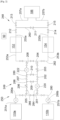
- the supply module 249 comprises an upstream pipe 280 and a downstream pipe 282.
- the upstream pipe 280 is fluidically connected between the supply pipes 251a and 251b and the pipe downstream 282 is fluidly connected between the first outlet pipe 253a and the second outlet pipe 253b.
- the power module 249 also comprises a first connecting pipe 284 and a second connecting pipe 286.
- the first connecting pipe 284 and the second connecting pipe 286 are fluidically connected in parallel between the upstream pipe 280 and the downstream pipe 282.
- the supply module 249 comprises, mounted on the first connecting pipe 284, a first two-way solenoid valve 201 and between the first solenoid valve 201 and the first sub-pipe 288, a first secondary pump 220 controlled by the control unit 50 and which ensures the movement of the dihydrogen towards the engine 106.
- the supply module 249 comprises, mounted on the first connecting pipe 284, a third two-way regulating solenoid valve 203 which makes it possible to adjust the flow rate of dihydrogen in the first connecting pipe 284 between the second sub-pipe 289 and the downstream pipe 282.
- the supply module 249 also comprises, mounted on the first connecting pipe 284, between the third solenoid valve 203 and the downstream pipe 282, a fourth two-way solenoid valve 204.
- the supply module 249 comprises, mounted on the second connecting pipe 286, a fifth two-way solenoid valve 205 and between the fifth solenoid valve 205 and the first sub-pipe 288, a sixth two-way regulating solenoid valve 206 which makes it possible to adjust the flow rate of dihydrogen in the second connecting pipe 286 between the first sub-pipe 288 and the upstream pipe 280.
- the supply module 249 comprises, mounted on the second connecting pipe 286, a seventh two-way solenoid valve 207.
- the supply module 249 comprises, mounted on the second connecting pipe 286, a second secondary pump 222 controlled by the control unit 50 and which ensures the movement of the dihydrogen towards the engine 106.
- the supply module 249 also comprises, mounted on the second connecting pipe 286, between the second secondary pump 222 and the downstream pipe 282, an eighth two-way solenoid valve 208.
- the power supply module 249 comprises, mounted on the first sub-pipe 288, a ninth two-way solenoid valve 209 and mounted on the second sub-pipe 289, a tenth two-way solenoid valve 210.
- Each solenoid valve is controlled to open and close by the control unit 50 as required.
- the hydrogen is channeled from the tanks 110a-b and driven by the pumps.
- the hydrogen thus flows through the upstream pipe 280, the first solenoid valve 201, the first secondary pump 220, then it joins the second secondary pump 222 and the eighth solenoid valve 208 to reach the outlet pipes 253a-b where it flows through the heaters 152 and 154, then through the distribution module 248 and the engine 106.
- the hydrogen passes through the second and tenth solenoid valves 202 and 210, or through the ninth and seventh solenoid valves 209 and 207.
- dihydrogen is taken at the fourth solenoid valve 204 to reach the second secondary pump 222 or the first secondary pump 220.
- the dihydrogen flows through the third solenoid valve 203, then the sixth solenoid valve 206 and the fifth solenoid valve 205.
- the dihydrogen passes through the tenth and seventh solenoid valves 210 and 207 or through the second and ninth solenoid valves 202 and 209.
- the dihydrogen can reach the second secondary pump 222.
- the amount of hydrogen that will recirculate depends on the degree of opening of the third and sixth solenoid valves 203 and 206.
- the control unit 50 commands the closing of the first 201, second 202 and ninth 209 solenoid valves to isolate the first secondary pump 220.
- the dihydrogen then passes through the second connecting pipe 286 to reach the second secondary pump 222 and there is no longer any recirculation through the sixth solenoid valve 206 but it can continue through the third solenoid valve 203.
- the control unit 50 commands the closing of the seventh 207, eighth 208 and tenth 210 solenoid valves to isolate the second secondary pump 222.
- the dihydrogen then passes only through the first connecting pipe 284 to reach the outlet pipes 253a-b and there is no longer any recirculation through the third solenoid valve 203 but it can continue through the sixth solenoid valve 206.
- the control unit 50 commands the closing of the fifth 205, seventh 207 and ninth 209 solenoid valves to isolate the sixth solenoid valve 206.
- the dihydrogen then passes through the normal route but only through the second 202 and tenth 210 solenoid valves between the first connecting pipe 284 and the second connecting pipe 286, and there is no longer any recirculation through the sixth solenoid valve 206 but it can continue through the third solenoid valve 203.
- the control unit 50 commands the closing of the second 202, fourth 204 and tenth 210 solenoid valves to isolate the third solenoid valve 203.
- the dihydrogen then passes through the normal route but only through the ninth 209 and seventh 207 solenoid valves between the first connecting pipe 284 and the second connecting pipe 286, and there is no further recirculation through the third solenoid valve 203 but it can continue through the sixth solenoid valve 206.
- the control unit 50 controls the closing of the first solenoid valve 201 and the second solenoid valve 202 and the ninth solenoid valve 209.
- control unit 50 controls the closing of the solenoid valves which are on either side of the leak and on the same connecting pipe 284, 286 and the closing of the solenoid valve of the sub-pipe 288, 289 which is in fluid communication with said part.
- the power module 349 is identical to the power module 249 of the first variant of the first embodiment, except that the second secondary pump 322 and the third solenoid valve 303 are swapped.
- the second secondary pump 322 is mounted on the first connecting pipe 284 between the second sub-pipe 289 and the fourth solenoid valve 204
- the third solenoid valve 303 is mounted on the second connecting pipe 286 between the second sub-pipe 289 and the eighth solenoid valve 208.
- the operation of the supply module 349 according to the second variant is similar to that of the supply module 249 according to the first variant except that in normal operation, the dihydrogen flows from the tanks 110a-b to the outlet pipes 253a-b passing only through the first connecting pipe 284 while the second connecting pipe 286 is used for recirculating the dihydrogen.
- the supply module 249, 349 comprises, mounted on the downstream pipe 282, three solenoid valves which are controlled by the control unit 50 where a solenoid valve is arranged between the first heater 152 and the second connecting pipe 286, a solenoid valve is arranged between the second connecting pipe 286 and the first connecting pipe 284 and a solenoid valve is arranged between the first connecting pipe 284 and the second heater 154.
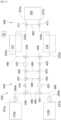
- the power module 449 also comprises a first connecting pipe 484 and a second connecting pipe 486.
- the first connecting pipe 484 and the second connecting pipe 486 are fluidically connected in parallel between the upstream pipe 480 and the downstream pipe 482.
- the power module 449 also includes a first sub-pipe 488 and a second sub-pipe 489 fluidically connected in parallel between the first connecting pipe 484 and the second connecting pipe 486.
- the first sub-pipe 488 is between the upstream pipe 480 and the second sub-pipe 489, and therefore, the second sub-pipe 489 is between the first sub-pipe 488 and the downstream pipe 482.
- the supply module 449 comprises a first three-way solenoid valve 401 with two channels fluidly connected to the upstream pipe 480 and one channel fluidly connected to the first connecting pipe 484.
- the power module 449 comprises a second three-way solenoid valve 402 with two channels fluidly connected to the first connecting pipe 484 and one channel fluidly connected to the first sub-pipe 488.
- the power module 449 comprises a third three-way solenoid valve 403 with two channels fluidly connected to the first connecting pipe 484 and one channel fluidly connected to the second sub-pipe 489.
- the supply module 449 comprises a fourth three-way solenoid valve 404 with two channels fluidly connected to the downstream pipe 482 and one channel fluidly connected to the first connecting pipe 484.
- the supply module 449 comprises, mounted on the first connecting pipe 484, a first secondary pump 420 which ensures the movement of the dihydrogen towards the engine 106.
- the supply module 449 comprises, mounted on the first connecting pipe 484, a fifth two-way regulating solenoid valve 405 which makes it possible to adjust the flow rate of dihydrogen in the first connecting pipe 484 between the second sub-pipe 489 and the downstream pipe 482.
- the supply module 449 comprises a sixth three-way solenoid valve 406 with two channels fluidly connected to the upstream pipe 480 and one channel fluidly connected to the second connecting pipe 486.
- the power module 449 comprises a seventh three-way solenoid valve 407 with two channels fluidly connected to the second connecting pipe 486 and one channel fluidly connected to the first sub-pipe 488.
- the power module 449 comprises an eighth three-way solenoid valve 408 with two channels fluidly connected to the second connecting pipe 486 and one channel fluidly connected to the second sub-pipe 489.
- the supply module 449 comprises a ninth three-way solenoid valve 409 with two channels fluidly connected to the downstream pipe 482 and one channel fluidly connected to the second connecting pipe 486.
- the supply module 449 comprises, mounted on the second connecting pipe 486, a tenth two-way regulating solenoid valve 410 which makes it possible to adjust the flow rate of dihydrogen in the second connecting pipe 486 between the first sub-pipe 488 and the upstream pipe 480.
- the supply module 449 comprises, mounted on the second connecting pipe 486, a second secondary pump 422 which ensures the movement of the dihydrogen towards the engine 106.
- Each solenoid valve is controlled to open and close by the control unit 50 as required.
- Each pump is controlled by the control unit 50 as needed.
- the dihydrogen is channeled from the tanks 110a-b and driven by the pumps.
- the dihydrogen thus flows through the upstream pipe 480, the first solenoid valve 401, the first secondary pump 420, then it joins the second secondary pump 422 and the ninth solenoid valve 409 to reach the pipes of outlet 253a-b where it flows through the heaters 152 and 154, then through the distribution module 448 and the engine 106.
- the dihydrogen passes through the second 402, third 403, seventh 407 and eighth 408 solenoid valves.
- dihydrogen is taken at the fourth solenoid valve 404 to reach the second secondary pump 422 or the first secondary pump 420.
- the dihydrogen flows through the fifth solenoid valve 405, then the tenth solenoid valve 410 and the sixth solenoid valve 406.
- the dihydrogen passes through the second 402, third 403, seventh 407 and eighth 408 solenoid valves.
- the dihydrogen can reach the second secondary pump 422.
- the amount of hydrogen that will recirculate depends on the degree of opening of the fifth 405 and tenth 410 solenoid valves.
- the control unit 50 commands the closing of the path of the first solenoid valve 401 and the path of the second solenoid valve 402 which are fluidically connected to the first connecting pipe 484 to isolate the first secondary pump 420.
- the dihydrogen then passes through the second connecting pipe 486 to reach the second secondary pump 422 and there is no longer any recirculation through the tenth solenoid valve 410, but it can continue through the fifth solenoid valve 405.
- control unit 50 commands the closing of the path of the eighth solenoid valve 408 and the path of the ninth solenoid valve 409 which are fluidically connected to the second connecting pipe 486 to isolate the second secondary pump 422.
- the dihydrogen then passes only through the first connecting pipe 484 to reach the outlet pipes 253a-b and there is no longer any recirculation through the fifth solenoid valve 405 but it can continue through the tenth solenoid valve 410.
- the control unit 50 commands the closing of the path of the sixth solenoid valve 406 and the path of the seventh solenoid valve 407 which are fluidically connected to the second connecting pipe 486 to isolate the tenth solenoid valve 410.
- the dihydrogen then passes through the normal path but there is no longer any recirculation through the tenth solenoid valve 410, but it can continue through the fifth solenoid valve 405.
- control unit 50 commands the closing of the path of the third solenoid valve 403 and the path of the fourth solenoid valve 404 which are fluidically connected to the second connecting pipe 486 to isolate the fifth solenoid valve 405.
- the dihydrogen then passes through the normal path but there is no longer any recirculation through the fifth solenoid valve 405 but it can continue through the tenth solenoid valve 410.
- the power module 549 is identical to the power module 449 of the first variant of the second embodiment, except that the second secondary pump 522 and the fifth solenoid valve 505 are interchanged.
- the second secondary pump 522 is mounted on the first connecting pipe 484 between the third solenoid valve 403 and the fourth solenoid valve 404
- the fifth solenoid valve 505 is mounted on the second connecting pipe 486 between the eighth solenoid valve 408 and the ninth solenoid valve 409.
- the operation of the supply module 549 according to the second variant is similar to that of the supply module 449 according to the first variant except that in normal operation, the dihydrogen flows from the tanks 110a-b to the outlet pipes 253a-b passing only through the first connecting pipe 484 while the second connecting pipe 486 is used for recirculating the dihydrogen.
- control unit 50 commands the closing of the channels of the solenoid valves which ensure the isolation of said element, that is to say the two channels which are on either side of said element on the same connecting pipe 484, 486 as the latter.
- control unit 50 controls the closing of the path of the first solenoid valve 401 and the path of the second solenoid valve 402.
- Fig. 2 and the Fig. 3 show the distribution module 248 according to a first variant and the Fig. 4 and the Fig. 5 show the distribution module 448 according to a second variant.
- the distribution module 248 according to the first variant is associated with the power supply system 250, 350 according to the first embodiment and the distribution module 448 according to the second variant is associated with the supply system 450, 550 according to the second embodiment, it is possible to use the distribution module 248 according to the first variant with the supply system 450, 550 according to the second embodiment and the distribution module 448 according to the second variant with the supply system 250, 350 according to the first embodiment.
- the first introduction pipe 255a is fluidically connected to the first distribution pipe 257a and the second introduction pipe 255b is fluidically connected to the second distribution pipe 257b.
- the distribution module 248 comprises a diverter pipe 260 fluidly connected between the first introduction pipe 255a and the second introduction pipe 255b and an eleventh two-way solenoid valve 211 mounted on the diverter pipe 260.
- the distribution module 248 also comprises, between the first heater 152 and the diversion pipe 260, a twelfth two-way solenoid valve 212 mounted on the first introduction pipe 255a and, between the diversion pipe 260 and the motor 106, a thirteenth solenoid valve 213 mounted on the first distribution pipe 257a.
- the distribution module 248 also comprises, between the second heater 154 and the diversion pipe 260, a fourteenth two-way solenoid valve 214 mounted on the second introduction pipe 255b and, between the diversion pipe 260 and the motor 106, a fifteenth solenoid valve 215 mounted on the second distribution pipe 257b.
- Each solenoid valve is controlled in opening and closing by the control unit 50.
- Such a system makes it possible to direct the dihydrogen towards the engine 106, whether it comes from the first heater 152 or the second heater 154.
- the control unit 50 commands the closing of the twelfth solenoid valve 212 and the dihydrogen circulates only through the second introduction pipe 255b then the first distribution pipe 257a and/or the second distribution pipe 257b.
- the principle is the same for the other pipes of the 248 distribution module which can be isolated in the event of a leak.
- the first introduction pipe 255a is fluidically connected to the first distribution pipe 257a and the second inlet pipe 255b is fluidically connected to the second distribution pipe 257b.
- the distribution module 448 comprises a diverter pipe 460 fluidly connected between the first introduction pipe 255a and the second introduction pipe 255b.
- the distribution module 448 comprises an eleventh three-way solenoid valve 411 where one way is fluidly connected to the first inlet pipe 255a, one way is fluidly connected to the diverter pipe 460 and one way is fluidly connected to the first distribution pipe 257a.
- the distribution module 448 comprises a twelfth three-way solenoid valve 412 where one way is fluidly connected to the second inlet pipe 255b, one way is fluidly connected to the diverter pipe 460 and one way is fluidly connected to the second distribution pipe 257b.
- Each solenoid valve is controlled in opening and closing by the control unit 50. Such a system makes it possible to direct the dihydrogen towards the engine 106 whether it comes from the first heater 152 or the second heater 154.
- the control unit 50 commands the closing of the path of the eleventh solenoid valve 411 which is fluidically connected to the first introduction pipe 255a and the dihydrogen circulates only through the second introduction pipe 255b then the first distribution pipe 257a and/or the second distribution pipe 257b.
- the principle is the same for the other pipes of the 448 distribution module which can be isolated in the event of a leak.
- control unit 50 comprises, connected by a communication bus: a processor or CPU (“Central Processing Unit” in English); a random access memory RAM (“Random Access Memory” in English); a read only memory ROM (“Read Only Memory” in English); a storage unit such as a hard disk or a storage media reader, such as an SD (“Secure Digital” in English) card reader; at least one communication interface, allowing for example the control unit to communicate with the solenoid valves, the pumps, etc.
- a communication bus a processor or CPU (“Central Processing Unit” in English); a random access memory RAM (“Random Access Memory” in English); a read only memory ROM (“Read Only Memory” in English); a storage unit such as a hard disk or a storage media reader, such as an SD (“Secure Digital” in English) card reader; at least one communication interface, allowing for example the control unit to communicate with the solenoid valves, the pumps, etc.
- a communication bus a processor or CPU (“Central Processing Unit” in English); a random access memory
- the processor is capable of executing instructions loaded into RAM from ROM, external memory (not shown), storage media (such as a card SD), or a communications network. When the equipment is powered on, the processor is able to read instructions from RAM and execute them. These instructions form a computer program causing the processor to implement all or part of the algorithms and steps described.
- All or part of the algorithms and steps described below may be implemented in software form by executing a set of instructions by a programmable machine, for example a DSP (“Digital Signal Processor”) or a microcontroller, or be implemented in hardware form by a machine or a dedicated component, for example an FPGA (“Field-Programmable Gate Array”) or an ASIC (“Application-Specific Integrated Circuit”).
- a programmable machine for example a DSP (“Digital Signal Processor”) or a microcontroller
- FPGA Field-Programmable Gate Array
- ASIC Application-Specific Integrated Circuit
Landscapes
- Engineering & Computer Science (AREA)
- Chemical & Material Sciences (AREA)
- Combustion & Propulsion (AREA)
- Mechanical Engineering (AREA)
- General Engineering & Computer Science (AREA)
- Chemical Kinetics & Catalysis (AREA)
- General Chemical & Material Sciences (AREA)
- Oil, Petroleum & Natural Gas (AREA)
- Aviation & Aerospace Engineering (AREA)
- Magnetically Actuated Valves (AREA)
- Pipeline Systems (AREA)
- Quick-Acting Or Multi-Walled Pipe Joints (AREA)
Claims (8)
- Versorgungssystem (250, 350, 450, 550) für ein Flugzeug (100), umfassend einen ersten und einen zweiten Tank (110a-b) für Diwasserstoff und ein Triebwerk (106), das Versorgungssystem (250, 350, 450, 550) umfassend:- ein Versorgungsmodul (249, 349, 449, 549), umfassend eine erste Auslassleitung (253a), eine zweite Auslassleitung (253b), eine erste Zuführleitung (251a), die mit einer ersten Hauptpumpe (290a) ausgestattet ist und dazu bestimmt ist, fluidisch an den ersten Tank (110a) angeschlossen zu sein, eine zweite Zuführleitung (251b), die mit einer zweiten Hauptpumpe (290b) ausgestattet ist und dazu bestimmt ist, fluidisch an den zweiten Tank (110b) angeschlossen zu sein, und Mittel, die dazu gestaltet sind, den Diwasserstoff von der ersten und der zweiten Zuführleitung (251a-b) alternierend zu der ersten Auslassleitung (253a) oder der zweiten Auslassleitung (253b) oder beiden zu leiten,- einen ersten Erhitzer (152),- einen zweiten Erwärmer (154),- ein Verteilungsmodul (248, 348), umfassend eine Einführleitung (255a), die fluidisch an die erste Auslassleitung (253a) über den ersten Erwärmer (152) angeschlossen ist, eine zweite Einführleitung (255b), die fluidisch an die zweite Auslassleitung (253b) über den zweiten Erwärmer (154) angeschlossen ist, eine erste Verteilungsleitung (257a) und eine zweite Verteilungsleitung (257b), die dazu bestimmt sind, fluidisch an das Triebwerk (106) angeschlossen zu sein, und Mittel, um den Diwasserstoff von der ersten und der zweiten Einführleitung (255a-b) alternierend zu der ersten Verteilungsleitung (257a) oder der zweiten Verteilungsleitung (257b) oder beiden zu leiten,- Detektionsmittel, die dazu vorgesehen sind, eine Störung in dem Versorgungsmodul (249, 349, 449, 549), und/oder dem Verteilungsmodul (248, 348) und/oder den ersten und zweiten Erwärmern (152, 154) zu detektieren und Informationen auszugeben, die für die detektierte Störung repräsentativ sind, und- eine Steuerungseinheit (50), die dazu eingerichtet ist, die Mittel des Versorgungsmoduls (249, 349, 449, 549) und/oder die Mittel des Verteilungsmoduls (248, 348) in Abhängigkeit von den von den Detektionsmitteln ausgegebenen Informationen zu steuern.
- Versorgungssystem (250) nach Anspruch 1, dadurch gekennzeichnet, dass das Versorgungsmodul (249) umfasst:- eine stromaufwärtige Leitung (280), die fluidisch zwischen der ersten und der zweiten Zuführleitung (251a, 251b) angeschlossen ist,- eine stromabwärtige Leitung (282), die fluidisch zwischen der ersten Auslassleitung (253a) und der zweiten Auslassleitung (253b) angeschlossen ist,- eine erste Verbindungsleitung (284) und eine zweite Verbindungsleitung (286), die fluidisch parallel zwischen der stromaufwärtigen Leitung (280) und der stromabwärtigen Leitung (282) angeschlossen sind,- eine erste Teilleitung (288) und eine zweite Teilleitung (289), die fluidisch parallel zwischen der ersten Verbindungsleitung (284) und der zweiten Verbindungsleitung (286) angeschlossen sind,- ein erstes Zweiwege-Magnetventil (201), das an der ersten Verbindungsleitung (284) zwischen der stromaufwärtigen Leitung (280) und der ersten Teilleitung (288) montiert ist,- eine erste sekundäre Pumpe (220), die an der ersten Verbindungsleitung (284) zwischen dem ersten Magnetventil (201) und der ersten Teilleitung (288) montiert ist,- ein zweites Zweiwege-Magnetventil (202), das an der ersten Verbindungsleitung (284) zwischen der ersten Teilleitung (288) und der zweiten Teilleitung (289) montiert ist,- ein drittes Zweiwege-Regelungsmagnetventil (203), das an der ersten Verbindungsleitung (284) zwischen der zweiten Teilleitung (289) und der stromabwärtigen Leitung (282) montiert ist,- ein viertes Zweiwege-Magnetventil (204), das an der ersten Verbindungsleitung (284) zwischen dem dritten Magnetventil (203) und der stromabwärtigen Leitung (282) montiert ist,- ein fünftes Zweiwege-Magnetventil (205), das an der zweiten Verbindungsleitung (286) zwischen der stromaufwärtigen Leitung (280) und der ersten Teilleitung (288) montiert ist,- ein sechstes Zweiwege-Regelungsmagnetventil (206), das an der zweiten Verbindungsleitung (286) zwischen dem fünften Magnetventil (205) und der ersten Teilleitung (288) montiert ist,- ein siebtes Zweiwege-Magnetventil (207), das an der zweiten Verbindungsleitung (286) zwischen der ersten Teilleitung (288) und der zweiten Teilleitung (289) montiert ist,- eine zweite sekundäre Pumpe (222), die an der zweiten Verbindungsleitung (286) zwischen der zweiten Teilleitung (289) und der stromabwärtigen Leitung (282) montiert ist,- ein achtes Zweiwege-Magnetventil (208), das an der zweiten Verbindungsleitung (286) zwischen der zweiten sekundären Pumpe (222) und der stromabwärtigen Leitung (282) montiert ist,- ein neuntes Zweiwege-Magnetventil (209), das an der ersten Teilleitung (288) montiert ist, und- ein zehntes Zweiwege-Magnetventil (210), das an der zweiten Teilleitung (289) montiert ist.
- Versorgungssystem (350) nach Anspruch 1, dadurch gekennzeichnet, dass das Versorgungsmodul (349) umfasst:- eine stromaufwärtige Leitung (280), die fluidisch zwischen der ersten und der zweiten Zuführleitung (251a, 251b) angeschlossen ist,- eine stromabwärtige Leitung (282), die fluidisch zwischen der ersten Auslassleitung (253a) und der zweiten Auslassleitung (253b) angeschlossen ist,- eine erste Verbindungsleitung (284) und eine zweite Verbindungsleitung (286), die fluidisch parallel zwischen der stromaufwärtigen Leitung (280) und der stromabwärtigen Leitung (282) angeschlossen sind,- eine erste Teilleitung (288) und eine zweite Teilleitung (289), die fluidisch parallel zwischen der ersten Verbindungsleitung (284) und der zweiten Verbindungsleitung (286) angeschlossen sind,- ein erstes Zweiwege-Magnetventil (201), das an der ersten Verbindungsleitung (284) zwischen der stromaufwärtigen Leitung (280) und der ersten Teilleitung (288) montiert ist,- eine erste sekundäre Pumpe (220), die an der ersten Verbindungsleitung (284) zwischen dem ersten Magnetventil (201) und der ersten Teilleitung (288) montiert ist,- ein zweites Zweiwege-Magnetventil (202), das an der ersten Verbindungsleitung (284) zwischen der ersten Teilleitung (288) und der zweiten Teilleitung (289) montiert ist,- eine zweite sekundäre Pumpe (322), die an der ersten Verbindungsleitung (284) zwischen der zweiten Teilleitung (289) und dem vierten Magnetventil (204) montiert ist,- ein viertes Zweiwege-Magnetventil (204), das an der ersten Verbindungsleitung (284) zwischen dem dritten Magnetventil (203) und der stromabwärtigen Leitung (282) montiert ist,- ein fünftes Zweiwege-Magnetventil (205), das an der zweiten Verbindungsleitung (286) zwischen der stromaufwärtigen Leitung (280) und der ersten Teilleitung (288) montiert ist,- ein sechstes Zweiwege-Regelungsmagnetventil (206), das an der zweiten Verbindungsleitung (286) zwischen dem fünften Magnetventil (205) und der ersten Teilleitung (288) montiert ist,- ein siebtes Zweiwege-Magnetventil (207), das an der zweiten Verbindungsleitung (286) zwischen der ersten Teilleitung (288) und der zweiten Teilleitung (289) montiert ist,- ein drittes Magnetventil (303), das an der zweiten Verbindungsleitung (286) zwischen der zweiten Teilleitung (289) und der stromabwärtigen Leitung (282) montiert ist,- ein achtes Zweiwege-Magnetventil (208), das an der zweiten Verbindungsleitung (286) zwischen der zweiten sekundären Pumpe (222) und der stromabwärtigen Leitung (282) montiert ist,- ein neuntes Zweiwege-Magnetventil (209), das an der ersten Teilleitung (288) montiert ist, und- ein zehntes Zweiwege-Magnetventil (210), das an der zweiten Teilleitung (289) montiert ist.
- Versorgungssystem (450) nach Anspruch 1, dadurch gekennzeichnet, dass das Versorgungsmodul (449) umfasst:- eine stromaufwärtige Leitung (480), die fluidisch zwischen der ersten und der zweiten Zuführleitung (251a, 251b) angeschlossen ist,- eine stromabwärtige Leitung (482), die fluidisch zwischen der ersten Auslassleitung (253a) und der zweiten Auslassleitung (253b) angeschlossen ist,- eine erste Verbindungsleitung (484) und eine zweite Verbindungsleitung (486), die fluidisch parallel zwischen der stromaufwärtigen Leitung (480) und der stromabwärtigen Leitung (482) angeschlossen sind,- eine erste Teilleitung (488) und eine zweite Teilleitung (489), die fluidisch parallel zwischen der ersten Verbindungsleitung (484) und der zweiten Verbindungsleitung (486) angeschlossen sind,- an dem Anschluss zwischen der stromaufwärtigen Leitung (480) und der ersten Verbindungsleitung (484) ein erstes Dreiwege-Magnetventil (401),- an dem Anschluss zwischen der ersten Verbindungsleitung (484) und der ersten Teilleitung (488) ein zweites Dreiwege-Magnetventil (402),- an dem Anschluss zwischen der ersten Verbindungsleitung (484) und der zweiten Teilleitung (489) ein drittes Dreiwege-Magnetventil (403),- an dem Anschluss zwischen der stromabwärtigen Leitung (482) und der ersten Verbindungsleitung (484) ein viertes Dreiwege-Magnetventil (404),- zwischen dem ersten Magnetventil (401) und dem zweiten Magnetventil (402) eine erste sekundäre Pumpe (420),- zwischen dem dritten Magnetventil (403) und dem vierten Magnetventil (404) ein fünftes Zweiwege-Regelungsmagnetventil (405),- an dem Anschluss zwischen der stromaufwärtigen Leitung (480) und der zweiten Verbindungsleitung (486) ein sechstes Dreiwege-Magnetventil (406),- an dem Anschluss zwischen der zweiten Verbindungsleitung (486) und der ersten Teilleitung (488) ein siebtes Dreiwege-Magnetventil (407),- an dem Anschluss zwischen der zweiten Verbindungsleitung (486) und der zweiten Teilleitung (489) ein achtes Dreiwege-Magnetventil (408),- an dem Anschluss zwischen der stromabwärtigen Leitung (482) und der zweiten Verbindungsleitung (486) ein neuntes Dreiwege-Magnetventil (409),- zwischen dem sechsten Magnetventil (406) und dem siebten Magnetventil (407) ein zehntes Zweiwege-Regelungsmagnetventil (410), und- zwischen dem achten Magnetventil (408) und dem neunten Magnetventil (409) eine zweite sekundäre Pumpe (422).
- Versorgungssystem (550) nach Anspruch 1, dadurch gekennzeichnet, dass das Versorgungsmodul (549) umfasst:- eine stromaufwärtige Leitung (480), die fluidisch zwischen der ersten und der zweiten Zuführleitung (251a, 251b) angeschlossen ist,- eine stromabwärtige Leitung (482), die fluidisch zwischen der ersten Auslassleitung (253a) und der zweiten Auslassleitung (253b) angeschlossen ist,- eine erste Verbindungsleitung (484) und eine zweite Verbindungsleitung (486), die fluidisch parallel zwischen der stromaufwärtigen Leitung (480) und der stromabwärtigen Leitung (482) angeschlossen sind,- eine erste Teilleitung (488) und eine zweite Teilleitung (489), die fluidisch parallel zwischen der ersten Verbindungsleitung (484) und der zweiten Verbindungsleitung (486) angeschlossen sind,- an dem Anschluss zwischen der stromaufwärtigen Leitung (480) und der ersten Verbindungsleitung (484) ein erstes Dreiwege-Magnetventil (401),- an dem Anschluss zwischen der ersten Verbindungsleitung (484) und der ersten Teilleitung (488) ein zweites Dreiwege-Magnetventil (402),- an dem Anschluss zwischen der ersten Verbindungsleitung (484) und der zweiten Teilleitung (489) ein drittes Dreiwege-Magnetventil (403),- an dem Anschluss zwischen der stromabwärtigen Leitung (482) und der ersten Verbindungsleitung (484) ein viertes Dreiwege-Magnetventil (404),- zwischen dem ersten Magnetventil (401) und dem zweiten Magnetventil (402) eine erste sekundäre Pumpe (420),- zwischen dem dritten Magnetventil (403) und dem vierten Magnetventil (404) eine zweite sekundäre Pumpe (522),- an dem Anschluss zwischen der stromaufwärtigen Leitung (480) und der zweiten Verbindungsleitung (486) ein sechstes Dreiwege-Magnetventil (406),- an dem Anschluss zwischen der zweiten Verbindungsleitung (486) und der ersten Teilleitung (488) ein siebtes Dreiwege-Magnetventil (407),- an dem Anschluss zwischen der zweiten Verbindungsleitung (486) und der zweiten Teilleitung (489) ein achtes Dreiwege-Magnetventil (408),- an dem Anschluss zwischen der stromabwärtigen Leitung (482) und der zweiten Verbindungsleitung (486) ein neuntes Dreiwege-Magnetventil (409),- zwischen dem sechsten Magnetventil (406) und dem siebten Magnetventil (407) ein zehntes Zweiwege-Regelungsmagnetventil (410), und- zwischen dem achten Magnetventil (408) und dem neunten Magnetventil (409) ein fünftes Zweiwege-Regelungsmagnetventil (505).
- Versorgungssystem (250, 350, 450, 550) nach einem der Ansprüche 1 bis 5, dadurch gekennzeichnet, dass die erste Einführleitung (255a) fluidisch an die erste Verteilungsleitung (257a) angeschlossen ist, dass die zweite Einführleitung (255b) fluidisch an die zweite Verteilungsleitung (257b) angeschlossen ist und dass das Verteilungsmodul (248) umfasst:- eine Bypassleitung (260), die fluidisch zwischen der ersten Einführleitung (255a) und der zweiten Einführleitung (255b) angeschlossen ist,- ein elftes Zweiwege-Magnetventil (211), das an der Bypassleitung (260) montiert ist,- zwischen dem ersten Erwärmer (152) und der Bypassleitung (260) ein zwölftes Zweiwege-Magnetventil (212), das an der ersten Einführleitung (255a) montiert ist,- zwischen der Bypassleitung (260) und dem Triebwerk (106) ein dreizehntes Magnetventil (213), das an der ersten Verteilungsleitung (257a) montiert ist,- zwischen dem zweiten Erwärmer (154) und der Bypassleitung (260) ein vierzehntes Zweiwege-Magnetventil (214), das an der zweiten Einführleitung (255b) montiert ist, und- zwischen der Bypassleitung (260) und dem Triebwerk (106) ein fünfzehntes Magnetventil (215), das an der zweiten Verteilungsleitung (257b) montiert ist.
- Versorgungssystem (250, 350, 450, 550) nach einem der Ansprüche 1 bis 5, dadurch gekennzeichnet, dass die erste Einführleitung (255a) fluidisch an die erste Verteilungsleitung (257a) angeschlossen ist, dass die zweite Einführleitung (255b) fluidisch an die zweite Verteilungsleitung (257b) angeschlossen ist und dass das Verteilungsmodul (448) umfasst:- eine Bypassleitung (460), die fluidisch zwischen der ersten Einführleitung (255a) und der zweiten Einführleitung (255b) angeschlossen ist,- an dem Anschluss zwischen der ersten Einführleitung (255a) und der Bypassleitung (460) ein elftes Dreiwege-Magnetventil (411), bei dem ein Weg fluidisch an die erste Einführleitung (255a) angeschlossen ist, ein Weg fluidisch an die Bypassleitung (460) angeschlossen ist und ein Weg fluidisch an die erste Verteilungsleitung (257a) angeschlossen ist,- an dem Anschluss zwischen der zweiten Einführleitung (255b) und der Bypassleitung (460) ein zwölftes Dreiwege-Magnetventil (412), bei dem ein Weg fluidisch an die zweite Einführleitung (255b) angeschlossen ist, ein Weg fluidisch an die Bypassleitung (460) angeschlossen ist und ein Weg fluidisch an die zweite Verteilungsleitung (257b) angeschlossen ist.
- Flugzeug (100), umfassend einen ersten und einen zweiten Tank (110a-b) für Diwasserstoff, mindestens ein Triebwerk (106) und, für jedes Triebwerk (106), ein Versorgungssystem (250, 350, 450, 550) nach einem der vorhergehenden Ansprüche, wobei jede der ersten und zweiten Zuführleitungen (251a-b) fluidisch an einen der ersten oder zweiten Tanks (110a-b) angeschlossen ist und wobei die ersten oder zweiten Verteilungsleitungen (257ab) fluidisch an das Triebwerk (106) angeschlossen sind.
Applications Claiming Priority (1)
| Application Number | Priority Date | Filing Date | Title |
|---|---|---|---|
| FR2207595 | 2022-07-25 |
Publications (2)
| Publication Number | Publication Date |
|---|---|
| EP4311779A1 EP4311779A1 (de) | 2024-01-31 |
| EP4311779B1 true EP4311779B1 (de) | 2025-05-14 |
Family
ID=83355580
Family Applications (1)
| Application Number | Title | Priority Date | Filing Date |
|---|---|---|---|
| EP23186890.2A Active EP4311779B1 (de) | 2022-07-25 | 2023-07-21 | System zur versorgung eines flugzeugmotors mit diwasserstoff |
Country Status (3)
| Country | Link |
|---|---|
| US (1) | US12291349B2 (de) |
| EP (1) | EP4311779B1 (de) |
| CN (1) | CN117449961A (de) |
Family Cites Families (9)
| Publication number | Priority date | Publication date | Assignee | Title |
|---|---|---|---|---|
| US20130074945A1 (en) * | 2011-09-28 | 2013-03-28 | General Electric Company | Fuel system |
| US9255664B2 (en) * | 2012-12-24 | 2016-02-09 | General Electric Company | Cryogenic fuel system with auxiliary power provided by boil-off gas |
| FR3094070B1 (fr) | 2019-03-21 | 2021-10-15 | Air Liquide | Dispositif et procédé de stockage et de fourniture de carburant fluide. |
| FR3114355A1 (fr) | 2020-09-23 | 2022-03-25 | Safran | Ensemble de stockage cryogénique de carburant liquéfié |
| JP7835752B2 (ja) | 2020-11-19 | 2026-03-25 | リンデ ゲゼルシャフト ミット ベシュレンクテル ハフツング | 方法及び搬送装置 |
| FR3120114A1 (fr) | 2021-02-25 | 2022-08-26 | Airbus Operations | Aéronef comportant un moteur et un système de refroidissement à base de dihydrogène |
| US12241424B2 (en) * | 2021-03-23 | 2025-03-04 | General Electric Company | Hydrogen fuel leak detection system |
| WO2022234176A1 (en) | 2021-05-07 | 2022-11-10 | Wärtsilä Finland Oy | Fuel storage and supply system, method of operating such a system and marine vessel |
| EP4265897B1 (de) * | 2022-04-22 | 2025-09-24 | Eaton Intelligent Power Limited | Wasserstoffbrennstoffsystem für flugzeuge |
-
2023
- 2023-07-21 EP EP23186890.2A patent/EP4311779B1/de active Active
- 2023-07-21 US US18/356,655 patent/US12291349B2/en active Active
- 2023-07-25 CN CN202310920661.5A patent/CN117449961A/zh active Pending
Also Published As
| Publication number | Publication date |
|---|---|
| US20240150033A1 (en) | 2024-05-09 |
| EP4311779A1 (de) | 2024-01-31 |
| CN117449961A (zh) | 2024-01-26 |
| US12291349B2 (en) | 2025-05-06 |
Similar Documents
| Publication | Publication Date | Title |
|---|---|---|
| EP1685025B1 (de) | Fluidkühlsystem für flugzeuge und flugzeug ausgestattet mit einem solchen system | |
| FR2999652A1 (fr) | Circuit de carburant d'une turbomachine | |
| EP4371885B1 (de) | Flugzeug mit einem wasserstoffversorgungssystem | |
| EP4187071B1 (de) | Kombiniertes system zur erwärmung von wasserstoff und kühlung von flüssigkeit für ein flugzeug und flugzeug mit solch einem system | |
| EP2069620A2 (de) | Vorrichtung zur verteilung einer kühlflüssigkeit in einem kraftfahrzeugmotor | |
| EP4311778B1 (de) | System zur versorgung eines flugzeugmotors mit diwasserstoff | |
| EP4311779B1 (de) | System zur versorgung eines flugzeugmotors mit diwasserstoff | |
| EP4030043B1 (de) | Antriebseinheit für luftfahrzeug, die ein belüftungssystem und ein brandschutzsystem umfasst | |
| EP4638275A1 (de) | Heizungsanlage für ein flugzeug mit einem dihydrogentank, einem motor und dihydrogenheizsystemen | |
| FR2720442A1 (fr) | Installation d'alimentation en carburant d'un turboréacteur. | |
| FR2862724A1 (fr) | Dispositif et procede de refroidissement d'un fluide hydraulique dans un aeronef, aeronef equipe d'un tel dispositif, et application d'un tel procede | |
| EP2859214A1 (de) | System zur energierückgewinnung aus einer abgasleitung | |
| EP4063630B1 (de) | Fahrzeug mit einer antriebsanlage mit mindestens einem verbrennungsmotor, der mit einer klimaanlage zusammenwirkt | |
| FR3003544A1 (fr) | Dispositif de surveillance et de coupure de l'alimentation en air de pressurisation d'un reservoir de carburant d'aeronef | |
| EP4435316B1 (de) | Modul für ein diwasserstoff-versorgungssystem für einen flugzeugmotor | |
| EP4293212B1 (de) | Gehäusesystem mit wärmetauscher zur erwärmung von dihydrogen | |
| FR2894563A1 (fr) | Circuit et procede pour realiser des echanges thermiques par fluide caloporteur dans un systeme de controle environnemental d'aeronef. | |
| FR3153078A1 (fr) | Aéronef comportant un système d’alimentation en dihydrogène et un système de traitement thermique du dihydrogène | |
| EP4471913B1 (de) | Kühlsystem für ein flugzeug | |
| EP4345009B1 (de) | Antriebseinheit für ein flugzeug | |
| WO2014041273A1 (fr) | Procede de gestion de la circulation d'un liquide de refroidissement | |
| FR3154149A1 (fr) | Ensemble propulsif pour aéronef | |
| EP3660415A1 (de) | Vorrichtung für die thermische regelung eines gebäudes, entsprechende anlage und entsprechendes verfahren | |
| FR2865004A1 (fr) | Dispositif de regulation thermique de l'air d'admission d'un moteur a combustion interne | |
| WO2017009549A1 (fr) | Dispositif de refroidissement d'une boucle de recirculation des gaz d'échappement d'un moteur de véhicule automobile |
Legal Events
| Date | Code | Title | Description |
|---|---|---|---|
| PUAI | Public reference made under article 153(3) epc to a published international application that has entered the european phase |
Free format text: ORIGINAL CODE: 0009012 |
|
| STAA | Information on the status of an ep patent application or granted ep patent |
Free format text: STATUS: THE APPLICATION HAS BEEN PUBLISHED |
|
| AK | Designated contracting states |
Kind code of ref document: A1 Designated state(s): AL AT BE BG CH CY CZ DE DK EE ES FI FR GB GR HR HU IE IS IT LI LT LU LV MC ME MK MT NL NO PL PT RO RS SE SI SK SM TR |
|
| STAA | Information on the status of an ep patent application or granted ep patent |
Free format text: STATUS: REQUEST FOR EXAMINATION WAS MADE |
|
| 17P | Request for examination filed |
Effective date: 20240726 |
|
| RBV | Designated contracting states (corrected) |
Designated state(s): AL AT BE BG CH CY CZ DE DK EE ES FI FR GB GR HR HU IE IS IT LI LT LU LV MC ME MK MT NL NO PL PT RO RS SE SI SK SM TR |
|
| GRAP | Despatch of communication of intention to grant a patent |
Free format text: ORIGINAL CODE: EPIDOSNIGR1 |
|
| STAA | Information on the status of an ep patent application or granted ep patent |
Free format text: STATUS: GRANT OF PATENT IS INTENDED |
|
| INTG | Intention to grant announced |
Effective date: 20241211 |
|
| GRAS | Grant fee paid |
Free format text: ORIGINAL CODE: EPIDOSNIGR3 |
|
| GRAA | (expected) grant |
Free format text: ORIGINAL CODE: 0009210 |
|
| STAA | Information on the status of an ep patent application or granted ep patent |
Free format text: STATUS: THE PATENT HAS BEEN GRANTED |
|
| AK | Designated contracting states |
Kind code of ref document: B1 Designated state(s): AL AT BE BG CH CY CZ DE DK EE ES FI FR GB GR HR HU IE IS IT LI LT LU LV MC ME MK MT NL NO PL PT RO RS SE SI SK SM TR |
|
| REG | Reference to a national code |
Ref country code: GB Ref legal event code: FG4D Free format text: NOT ENGLISH |
|
| REG | Reference to a national code |
Ref country code: CH Ref legal event code: EP |
|
| REG | Reference to a national code |
Ref country code: IE Ref legal event code: FG4D Free format text: LANGUAGE OF EP DOCUMENT: FRENCH |
|
| REG | Reference to a national code |
Ref country code: DE Ref legal event code: R096 Ref document number: 602023003457 Country of ref document: DE |
|
| REG | Reference to a national code |
Ref country code: NL Ref legal event code: MP Effective date: 20250514 |
|
| PG25 | Lapsed in a contracting state [announced via postgrant information from national office to epo] |
Ref country code: FI Free format text: LAPSE BECAUSE OF FAILURE TO SUBMIT A TRANSLATION OF THE DESCRIPTION OR TO PAY THE FEE WITHIN THE PRESCRIBED TIME-LIMIT Effective date: 20250514 Ref country code: PT Free format text: LAPSE BECAUSE OF FAILURE TO SUBMIT A TRANSLATION OF THE DESCRIPTION OR TO PAY THE FEE WITHIN THE PRESCRIBED TIME-LIMIT Effective date: 20250915 Ref country code: ES Free format text: LAPSE BECAUSE OF FAILURE TO SUBMIT A TRANSLATION OF THE DESCRIPTION OR TO PAY THE FEE WITHIN THE PRESCRIBED TIME-LIMIT Effective date: 20250514 |
|
| PGFP | Annual fee paid to national office [announced via postgrant information from national office to epo] |
Ref country code: DE Payment date: 20250722 Year of fee payment: 3 |
|
| REG | Reference to a national code |
Ref country code: LT Ref legal event code: MG9D |
|
| PG25 | Lapsed in a contracting state [announced via postgrant information from national office to epo] |
Ref country code: NO Free format text: LAPSE BECAUSE OF FAILURE TO SUBMIT A TRANSLATION OF THE DESCRIPTION OR TO PAY THE FEE WITHIN THE PRESCRIBED TIME-LIMIT Effective date: 20250814 Ref country code: GR Free format text: LAPSE BECAUSE OF FAILURE TO SUBMIT A TRANSLATION OF THE DESCRIPTION OR TO PAY THE FEE WITHIN THE PRESCRIBED TIME-LIMIT Effective date: 20250815 |
|
| PG25 | Lapsed in a contracting state [announced via postgrant information from national office to epo] |
Ref country code: NL Free format text: LAPSE BECAUSE OF FAILURE TO SUBMIT A TRANSLATION OF THE DESCRIPTION OR TO PAY THE FEE WITHIN THE PRESCRIBED TIME-LIMIT Effective date: 20250514 Ref country code: PL Free format text: LAPSE BECAUSE OF FAILURE TO SUBMIT A TRANSLATION OF THE DESCRIPTION OR TO PAY THE FEE WITHIN THE PRESCRIBED TIME-LIMIT Effective date: 20250514 |
|
| REG | Reference to a national code |
Ref country code: AT Ref legal event code: MK05 Ref document number: 1794621 Country of ref document: AT Kind code of ref document: T Effective date: 20250514 |
|
| PG25 | Lapsed in a contracting state [announced via postgrant information from national office to epo] |
Ref country code: BG Free format text: LAPSE BECAUSE OF FAILURE TO SUBMIT A TRANSLATION OF THE DESCRIPTION OR TO PAY THE FEE WITHIN THE PRESCRIBED TIME-LIMIT Effective date: 20250514 |
|
| PG25 | Lapsed in a contracting state [announced via postgrant information from national office to epo] |
Ref country code: HR Free format text: LAPSE BECAUSE OF FAILURE TO SUBMIT A TRANSLATION OF THE DESCRIPTION OR TO PAY THE FEE WITHIN THE PRESCRIBED TIME-LIMIT Effective date: 20250514 |
|
| PG25 | Lapsed in a contracting state [announced via postgrant information from national office to epo] |
Ref country code: AT Free format text: LAPSE BECAUSE OF FAILURE TO SUBMIT A TRANSLATION OF THE DESCRIPTION OR TO PAY THE FEE WITHIN THE PRESCRIBED TIME-LIMIT Effective date: 20250514 |
|
| PGFP | Annual fee paid to national office [announced via postgrant information from national office to epo] |
Ref country code: FR Payment date: 20250725 Year of fee payment: 3 |
|
| PG25 | Lapsed in a contracting state [announced via postgrant information from national office to epo] |
Ref country code: RS Free format text: LAPSE BECAUSE OF FAILURE TO SUBMIT A TRANSLATION OF THE DESCRIPTION OR TO PAY THE FEE WITHIN THE PRESCRIBED TIME-LIMIT Effective date: 20250814 |
|
| PG25 | Lapsed in a contracting state [announced via postgrant information from national office to epo] |
Ref country code: IS Free format text: LAPSE BECAUSE OF FAILURE TO SUBMIT A TRANSLATION OF THE DESCRIPTION OR TO PAY THE FEE WITHIN THE PRESCRIBED TIME-LIMIT Effective date: 20250914 |
|
| PG25 | Lapsed in a contracting state [announced via postgrant information from national office to epo] |
Ref country code: LV Free format text: LAPSE BECAUSE OF FAILURE TO SUBMIT A TRANSLATION OF THE DESCRIPTION OR TO PAY THE FEE WITHIN THE PRESCRIBED TIME-LIMIT Effective date: 20250514 |
|
| PG25 | Lapsed in a contracting state [announced via postgrant information from national office to epo] |
Ref country code: SM Free format text: LAPSE BECAUSE OF FAILURE TO SUBMIT A TRANSLATION OF THE DESCRIPTION OR TO PAY THE FEE WITHIN THE PRESCRIBED TIME-LIMIT Effective date: 20250514 Ref country code: DK Free format text: LAPSE BECAUSE OF FAILURE TO SUBMIT A TRANSLATION OF THE DESCRIPTION OR TO PAY THE FEE WITHIN THE PRESCRIBED TIME-LIMIT Effective date: 20250514 |
|
| PG25 | Lapsed in a contracting state [announced via postgrant information from national office to epo] |
Ref country code: CZ Free format text: LAPSE BECAUSE OF FAILURE TO SUBMIT A TRANSLATION OF THE DESCRIPTION OR TO PAY THE FEE WITHIN THE PRESCRIBED TIME-LIMIT Effective date: 20250514 |
|
| PG25 | Lapsed in a contracting state [announced via postgrant information from national office to epo] |
Ref country code: EE Free format text: LAPSE BECAUSE OF FAILURE TO SUBMIT A TRANSLATION OF THE DESCRIPTION OR TO PAY THE FEE WITHIN THE PRESCRIBED TIME-LIMIT Effective date: 20250514 |
|
| PG25 | Lapsed in a contracting state [announced via postgrant information from national office to epo] |
Ref country code: SK Free format text: LAPSE BECAUSE OF FAILURE TO SUBMIT A TRANSLATION OF THE DESCRIPTION OR TO PAY THE FEE WITHIN THE PRESCRIBED TIME-LIMIT Effective date: 20250514 |
|
| PG25 | Lapsed in a contracting state [announced via postgrant information from national office to epo] |
Ref country code: IT Free format text: LAPSE BECAUSE OF FAILURE TO SUBMIT A TRANSLATION OF THE DESCRIPTION OR TO PAY THE FEE WITHIN THE PRESCRIBED TIME-LIMIT Effective date: 20250514 |
|
| REG | Reference to a national code |
Ref country code: DE Ref legal event code: R097 Ref document number: 602023003457 Country of ref document: DE |
|
| PG25 | Lapsed in a contracting state [announced via postgrant information from national office to epo] |
Ref country code: RO Free format text: LAPSE BECAUSE OF FAILURE TO SUBMIT A TRANSLATION OF THE DESCRIPTION OR TO PAY THE FEE WITHIN THE PRESCRIBED TIME-LIMIT Effective date: 20250514 |
|
| PG25 | Lapsed in a contracting state [announced via postgrant information from national office to epo] |
Ref country code: LU Free format text: LAPSE BECAUSE OF NON-PAYMENT OF DUE FEES Effective date: 20250721 |
|
| PLBE | No opposition filed within time limit |
Free format text: ORIGINAL CODE: 0009261 |
|
| STAA | Information on the status of an ep patent application or granted ep patent |
Free format text: STATUS: NO OPPOSITION FILED WITHIN TIME LIMIT |
|
| REG | Reference to a national code |
Ref country code: CH Ref legal event code: L10 Free format text: ST27 STATUS EVENT CODE: U-0-0-L10-L00 (AS PROVIDED BY THE NATIONAL OFFICE) Effective date: 20260325 |
|
| REG | Reference to a national code |
Ref country code: BE Ref legal event code: MM Effective date: 20250731 |
|
| PG25 | Lapsed in a contracting state [announced via postgrant information from national office to epo] |
Ref country code: BE Free format text: LAPSE BECAUSE OF NON-PAYMENT OF DUE FEES Effective date: 20250731 |
|
| 26N | No opposition filed |
Effective date: 20260217 |