EP4187071B1 - Kombiniertes system zur erwärmung von wasserstoff und kühlung von flüssigkeit für ein flugzeug und flugzeug mit solch einem system - Google Patents
Kombiniertes system zur erwärmung von wasserstoff und kühlung von flüssigkeit für ein flugzeug und flugzeug mit solch einem system Download PDFInfo
- Publication number
- EP4187071B1 EP4187071B1 EP22209957.4A EP22209957A EP4187071B1 EP 4187071 B1 EP4187071 B1 EP 4187071B1 EP 22209957 A EP22209957 A EP 22209957A EP 4187071 B1 EP4187071 B1 EP 4187071B1
- Authority
- EP
- European Patent Office
- Prior art keywords
- heat
- dihydrogen
- transfer fluid
- exchange
- engine
- Prior art date
- Legal status (The legal status is an assumption and is not a legal conclusion. Google has not performed a legal analysis and makes no representation as to the accuracy of the status listed.)
- Active
Links
Images

Classifications
-
- B—PERFORMING OPERATIONS; TRANSPORTING
- B64—AIRCRAFT; AVIATION; COSMONAUTICS
- B64D—EQUIPMENT FOR FITTING IN OR TO AIRCRAFT; FLIGHT SUITS; PARACHUTES; ARRANGEMENT OR MOUNTING OF POWER PLANTS OR PROPULSION TRANSMISSIONS IN AIRCRAFT
- B64D13/00—Arrangements or adaptations of air-treatment apparatus for aircraft crew or passengers, or freight space
- B64D13/06—Arrangements or adaptations of air-treatment apparatus for aircraft crew or passengers, or freight space the air being conditioned
- B64D13/08—Arrangements or adaptations of air-treatment apparatus for aircraft crew or passengers, or freight space the air being conditioned the air being heated or cooled
-
- F—MECHANICAL ENGINEERING; LIGHTING; HEATING; WEAPONS; BLASTING
- F02—COMBUSTION ENGINES; HOT-GAS OR COMBUSTION-PRODUCT ENGINE PLANTS
- F02C—GAS-TURBINE PLANTS; AIR INTAKES FOR JET-PROPULSION PLANTS; CONTROLLING FUEL SUPPLY IN AIR-BREATHING JET-PROPULSION PLANTS
- F02C7/00—Features, components parts, details or accessories, not provided for in, or of interest apart form groups F02C1/00 - F02C6/00; Air intakes for jet-propulsion plants
- F02C7/12—Cooling of plants
- F02C7/14—Cooling of plants of fluids in the plant, e.g. lubricant or fuel
-
- B—PERFORMING OPERATIONS; TRANSPORTING
- B64—AIRCRAFT; AVIATION; COSMONAUTICS
- B64D—EQUIPMENT FOR FITTING IN OR TO AIRCRAFT; FLIGHT SUITS; PARACHUTES; ARRANGEMENT OR MOUNTING OF POWER PLANTS OR PROPULSION TRANSMISSIONS IN AIRCRAFT
- B64D37/00—Arrangements in connection with fuel supply for power plant
- B64D37/34—Conditioning fuel, e.g. heating
-
- B—PERFORMING OPERATIONS; TRANSPORTING
- B64—AIRCRAFT; AVIATION; COSMONAUTICS
- B64D—EQUIPMENT FOR FITTING IN OR TO AIRCRAFT; FLIGHT SUITS; PARACHUTES; ARRANGEMENT OR MOUNTING OF POWER PLANTS OR PROPULSION TRANSMISSIONS IN AIRCRAFT
- B64D27/00—Arrangement or mounting of power plants in aircraft; Aircraft characterised by the type or position of power plants
- B64D27/02—Aircraft characterised by the type or position of power plants
- B64D27/10—Aircraft characterised by the type or position of power plants of gas-turbine type
-
- B—PERFORMING OPERATIONS; TRANSPORTING
- B64—AIRCRAFT; AVIATION; COSMONAUTICS
- B64D—EQUIPMENT FOR FITTING IN OR TO AIRCRAFT; FLIGHT SUITS; PARACHUTES; ARRANGEMENT OR MOUNTING OF POWER PLANTS OR PROPULSION TRANSMISSIONS IN AIRCRAFT
- B64D33/00—Arrangement in aircraft of power plant parts or auxiliaries not otherwise provided for
- B64D33/08—Arrangement in aircraft of power plant parts or auxiliaries not otherwise provided for of power plant cooling systems
-
- B—PERFORMING OPERATIONS; TRANSPORTING
- B64—AIRCRAFT; AVIATION; COSMONAUTICS
- B64D—EQUIPMENT FOR FITTING IN OR TO AIRCRAFT; FLIGHT SUITS; PARACHUTES; ARRANGEMENT OR MOUNTING OF POWER PLANTS OR PROPULSION TRANSMISSIONS IN AIRCRAFT
- B64D37/00—Arrangements in connection with fuel supply for power plant
- B64D37/30—Fuel systems for specific fuels
-
- F—MECHANICAL ENGINEERING; LIGHTING; HEATING; WEAPONS; BLASTING
- F02—COMBUSTION ENGINES; HOT-GAS OR COMBUSTION-PRODUCT ENGINE PLANTS
- F02C—GAS-TURBINE PLANTS; AIR INTAKES FOR JET-PROPULSION PLANTS; CONTROLLING FUEL SUPPLY IN AIR-BREATHING JET-PROPULSION PLANTS
- F02C3/00—Gas-turbine plants characterised by the use of combustion products as the working fluid
- F02C3/20—Gas-turbine plants characterised by the use of combustion products as the working fluid using a special fuel, oxidant, or dilution fluid to generate the combustion products
- F02C3/22—Gas-turbine plants characterised by the use of combustion products as the working fluid using a special fuel, oxidant, or dilution fluid to generate the combustion products the fuel or oxidant being gaseous at standard temperature and pressure
-
- F—MECHANICAL ENGINEERING; LIGHTING; HEATING; WEAPONS; BLASTING
- F02—COMBUSTION ENGINES; HOT-GAS OR COMBUSTION-PRODUCT ENGINE PLANTS
- F02C—GAS-TURBINE PLANTS; AIR INTAKES FOR JET-PROPULSION PLANTS; CONTROLLING FUEL SUPPLY IN AIR-BREATHING JET-PROPULSION PLANTS
- F02C7/00—Features, components parts, details or accessories, not provided for in, or of interest apart form groups F02C1/00 - F02C6/00; Air intakes for jet-propulsion plants
- F02C7/22—Fuel supply systems
- F02C7/224—Heating fuel before feeding to the burner
-
- F—MECHANICAL ENGINEERING; LIGHTING; HEATING; WEAPONS; BLASTING
- F02—COMBUSTION ENGINES; HOT-GAS OR COMBUSTION-PRODUCT ENGINE PLANTS
- F02M—SUPPLYING COMBUSTION ENGINES IN GENERAL WITH COMBUSTIBLE MIXTURES OR CONSTITUENTS THEREOF
- F02M21/00—Apparatus for supplying engines with non-liquid fuels, e.g. gaseous fuels stored in liquid form
- F02M21/02—Apparatus for supplying engines with non-liquid fuels, e.g. gaseous fuels stored in liquid form for gaseous fuels
- F02M21/0203—Apparatus for supplying engines with non-liquid fuels, e.g. gaseous fuels stored in liquid form for gaseous fuels characterised by the type of gaseous fuel
- F02M21/0206—Non-hydrocarbon fuels, e.g. hydrogen, ammonia or carbon monoxide
-
- F—MECHANICAL ENGINEERING; LIGHTING; HEATING; WEAPONS; BLASTING
- F02—COMBUSTION ENGINES; HOT-GAS OR COMBUSTION-PRODUCT ENGINE PLANTS
- F02M—SUPPLYING COMBUSTION ENGINES IN GENERAL WITH COMBUSTIBLE MIXTURES OR CONSTITUENTS THEREOF
- F02M21/00—Apparatus for supplying engines with non-liquid fuels, e.g. gaseous fuels stored in liquid form
- F02M21/02—Apparatus for supplying engines with non-liquid fuels, e.g. gaseous fuels stored in liquid form for gaseous fuels
- F02M21/0218—Details on the gaseous fuel supply system, e.g. tanks, valves, pipes, pumps, rails, injectors or mixers
- F02M21/0287—Details on the gaseous fuel supply system, e.g. tanks, valves, pipes, pumps, rails, injectors or mixers characterised by the transition from liquid to gaseous phase ; Injection in liquid phase; Cooling and low temperature storage
-
- B—PERFORMING OPERATIONS; TRANSPORTING
- B64—AIRCRAFT; AVIATION; COSMONAUTICS
- B64D—EQUIPMENT FOR FITTING IN OR TO AIRCRAFT; FLIGHT SUITS; PARACHUTES; ARRANGEMENT OR MOUNTING OF POWER PLANTS OR PROPULSION TRANSMISSIONS IN AIRCRAFT
- B64D13/00—Arrangements or adaptations of air-treatment apparatus for aircraft crew or passengers, or freight space
- B64D13/06—Arrangements or adaptations of air-treatment apparatus for aircraft crew or passengers, or freight space the air being conditioned
- B64D2013/0603—Environmental Control Systems
- B64D2013/0614—Environmental Control Systems with subsystems for cooling avionics
-
- B—PERFORMING OPERATIONS; TRANSPORTING
- B64—AIRCRAFT; AVIATION; COSMONAUTICS
- B64D—EQUIPMENT FOR FITTING IN OR TO AIRCRAFT; FLIGHT SUITS; PARACHUTES; ARRANGEMENT OR MOUNTING OF POWER PLANTS OR PROPULSION TRANSMISSIONS IN AIRCRAFT
- B64D13/00—Arrangements or adaptations of air-treatment apparatus for aircraft crew or passengers, or freight space
- B64D13/06—Arrangements or adaptations of air-treatment apparatus for aircraft crew or passengers, or freight space the air being conditioned
- B64D2013/0603—Environmental Control Systems
- B64D2013/0659—Environmental Control Systems comprising provisions for cooling fuel systems
-
- B—PERFORMING OPERATIONS; TRANSPORTING
- B64—AIRCRAFT; AVIATION; COSMONAUTICS
- B64D—EQUIPMENT FOR FITTING IN OR TO AIRCRAFT; FLIGHT SUITS; PARACHUTES; ARRANGEMENT OR MOUNTING OF POWER PLANTS OR PROPULSION TRANSMISSIONS IN AIRCRAFT
- B64D13/00—Arrangements or adaptations of air-treatment apparatus for aircraft crew or passengers, or freight space
- B64D13/06—Arrangements or adaptations of air-treatment apparatus for aircraft crew or passengers, or freight space the air being conditioned
- B64D2013/0603—Environmental Control Systems
- B64D2013/0674—Environmental Control Systems comprising liquid subsystems
Definitions
- the present invention relates to the field of heat exchanges and relates in particular to an installation, in an aircraft, for heating and cooling fluids.
- Heating of dihydrogen is usually carried out by means of heat exchange with a heat source from the exhaust gases of the engine turbine.
- liquid dihydrogen as a cold source to cool other fluids in the aircraft, such as oil or air, for example engine lubricating oil or compressed air recovered from the engine and used for the air conditioning of the aircraft cabin.
- a heat exchange between the liquid dihydrogen and the fluids would thus make it possible to both heat the dihydrogen and cool the aircraft fluids.
- a solution envisaged by the inventors could consist of using a common circuit comprising a heat transfer fluid allowing, by means of successive heat exchanges, the recovery of heat from the exhaust gases, heating of the dihydrogen, and cooling of the aircraft fluids such as oil and compressed air.
- An object of the present invention is to propose a method for combined cooling and heating in an aircraft, the aircraft comprising an engine configured to use dihydrogen as fuel, the dihydrogen being stored in liquid form in a tank and being used in gaseous form in the engine, the engine being a turboprop.
- the dihydrogen is conveyed from the tank to the engine via a pipe called the main pipe, and the method comprises the steps of: bypassing, parallel to a predefined section of the main pipe, part of the flow of dihydrogen in a pipe called the bypass pipe; circulating, in a first closed circuit, a first heat transfer fluid; performing a first heat exchange between the first heat transfer fluid and the dihydrogen circulating in the bypass pipe; and performing at least one second heat exchange, called a secondary heat exchange, each secondary heat exchange being performed between the first heat transfer fluid and a fluid used in the aircraft and requiring cooling, called the useful fluid.
- the method further comprises steps of: circulating, in a second closed circuit, a second heat transfer fluid; performing a third heat exchange, between the second heat transfer fluid and the dihydrogen circulating in a part of the main pipe; and performing a fourth heat exchange between the second heat transfer fluid and an exhaust gas from a turbine of the engine.
- liquid dihydrogen so that it can be used as fuel in the engine while cooling a useful fluid without the risk of the useful fluid freezing.
- the third heat exchange is carried out downstream of the predefined section of the main pipe.
- the third heat exchange is carried out upstream of the predefined section of the main pipe.
- first heat transfer fluid having a narrower operating range: it is not necessary to use a first heat transfer fluid operating at temperatures low enough to withstand significant heat loss linked to interaction with liquid hydrogen.
- the first heat transfer fluid has a narrower operating temperature range than the operating temperature range of the second heat transfer fluid.
- the useful fluid is oil or compressed air from the engine and intended to be used in an air conditioning system of the aircraft.
- the method comprises a first secondary heat exchange between the first heat transfer fluid and a first useful fluid and a second secondary heat exchange between the first heat transfer fluid and a second useful fluid, the first useful fluid being oil and the second useful fluid being compressed air from the engine and intended to be used in an air conditioning system of the aircraft.
- the method further comprises regulating the flow of dihydrogen circulating in the bypass pipe according to a temperature of the useful fluid measured at the outlet of the secondary heat exchange through which said useful fluid passes.
- the method further comprises regulating the flow of dihydrogen circulating in the bypass pipe according to a temperature of the first heat transfer fluid measured at the inlet of the first heat exchange.
- the first circulator corresponds to a pump.
- the second circulator corresponds to a pump.
- the invention also relates to an aircraft comprising at least one such system.
- FIG. 1 thus schematically illustrates a first example of embodiment of a combined heating and cooling system 100 intended to implement heat exchanges in an aircraft such as the aircraft 1 shown in the Fig. 5 .
- the system 100 comprises a tank 13 storing dihydrogen 1001 in liquid form.
- the temperature of the dihydrogen 1001 in the tank 13 is for example -253°C.
- the system 100 further comprises a pipe, called the main pipe 11, intended to transporting the dihydrogen 1001 from the tank 13 to a combustion chamber 142 of an engine 14 of the aircraft where it is used as fuel.
- the dihydrogen 1001 is circulated using a circulator 109 such as a pump located on the main line 11 at the outlet of the tank 13.
- the main line 11 comprises a fuel metering valve 112, located at the inlet of the combustion chamber 142.
- the fuel metering valve 112 makes it possible to inject a predefined quantity of dihydrogen 1001 into the combustion chamber 142.
- the engine 14 is a turboprop and further comprises a compressor 141 intended to compress air entering the combustion chamber 142 as well as a turbine 143 located at the outlet of the combustion chamber 142.
- the system 100 further comprises a pipe, called a bypass pipe 12, separate from the main pipe 11 and located in bypass relative to a predefined section 111 of the main pipe 11.
- the bypass pipe 12 is intended to transport, between an inlet of the bypass pipe 12 and an outlet of the bypass pipe 12, a portion of the flow of dihydrogen 1001 passing through the main pipe 11 and coming from the tank 13.
- the other portion of said flow of dihydrogen 1001 passing through the main pipe 11 is transported in parallel in the predefined section 111 of the main pipe 11, between the inlet of the bypass pipe 12 and the outlet of the bypass pipe 12.
- the system 100 further comprises a flow controller 121 located on the bypass line 12.
- the flow controller 121 is controlled by a control unit and makes it possible to regulate the flow of dihydrogen 1001 passing through the bypass line 12.
- the system 100 comprises a first closed circuit 17, in which a first heat transfer fluid is circulated in a predefined direction, for example using a circulator 107 such as a pump.
- the first closed circuit 17 comprises a first heat exchanger 101 and at least one second heat exchanger 102, called a secondary heat exchanger.
- the system 100 further comprises a second closed circuit 18, in which a second heat transfer fluid is circulated in a predefined direction, for example using a circulator 108 such as a pump.
- the second closed circuit 18 comprises a third heat exchanger 103 and a fourth heat exchanger 104.
- Each heat exchanger 101, 102, 103, 104 makes it possible to carry out a heat exchange between two fluids without mixing them, in other words to transfer heat from one fluid to the other fluid through an exchange surface.
- the first heat exchanger 101 makes it possible to carry out a first heat exchange between the first heat transfer fluid and the dihydrogen 1001 passing through the bypass pipe 12.
- the first heat exchange results in a transfer of heat from the first heat transfer fluid to the dihydrogen 1001 passing through the bypass pipe 12 and thus makes it possible to cool the first heat transfer fluid and to heat part of the flow of dihydrogen 1001.
- the secondary heat exchanger 102 makes it possible to carry out a second heat exchange, called secondary heat exchange, between the first heat transfer fluid and a fluid used in the aircraft and which needs to be cooled, called useful fluid.
- the useful fluid is transported in a pipe 15 which can be a closed circuit 151 (not shown in the Fig. 1 but visible on the Fig. 3 ) or a pipe carrying the useful fluid from a recovery zone 1521 (not shown in the Fig. 1 but visible on the Fig. 3 ) to a usage area 1522 (not shown on the Fig. 1 but visible on the Fig. 3 ).
- the useful fluid is for example oil or compressed air.
- the third heat exchanger 103 makes it possible to carry out a third heat exchange between the second heat transfer fluid and the dihydrogen 1001 transported by the main pipe 11.
- the third heat exchange results in a transfer of heat from the second heat transfer fluid to the dihydrogen 1001, and thus makes it possible to cool the second heat transfer fluid and to heat the dihydrogen 1001.
- the third heat exchange results in a heat supply to the dihydrogen 1001 sufficient for the dihydrogen 1001, liquid at the inlet of the third heat exchanger 103, to vaporize, and to reach a temperature greater than 0°C so as to allow stable combustion in the combustion chamber 142.
- the dihydrogen 1001 is thus in the gaseous state at the outlet of the third heat exchanger 103 and can then be used as fuel in the engine 14.
- the dihydrogen 1001 is in a liquid state in the part of the main pipe 11 located between the tank 13 and the third heat exchanger 103 and in a gaseous state in the part of the main pipe 11 located between the third heat exchanger 103 and
- the third heat exchanger 103 is located downstream of the predefined section 111 of the main pipe 11.
- An element located downstream of a An identified area of a conduit is located on the opposite side of the identified area from a source of a fluid flowing in said conduit.
- An element located upstream of an identified area of a conduit is located on the same side of the identified area as the source of a fluid flowing in said conduit.
- the source of the dihydrogen 1001 flowing in the main pipe 11 and the bypass pipe 12 is the tank 13.
- the third heat exchanger 103 is located on the side of the predefined section 111 which is opposite the tank 13. The dihydrogen 1001 is then in a liquid state in the predefined section 111 and in the bypass pipe 12.
- the fourth heat exchanger 104 makes it possible to carry out a fourth heat exchange between the second heat transfer fluid and an exhaust gas coming from the turbine 143 of the engine 14 and transported in an exhaust gas pipe 144.
- the fourth heat exchange causes a transfer of heat from the exhaust gas to the second heat transfer fluid, and thus makes it possible to heat the second heat transfer fluid.
- the first heat transfer fluid may be, for example, water glycol.
- the water glycol comprises water and comprises a proportion of ethylene glycol or propylene glycol and is used as a heat transfer fluid in the liquid state.
- the operating temperature of the water glycol is defined between its melting temperature and its boiling temperature, which vary according to the proportion of ethylene glycol or propylene glycol. In particular, the higher the proportion of ethylene glycol, the lower the melting temperature of the water glycol.
- the first heat transfer fluid may be a gas such as nitrogen or helium.
- the second heat transfer fluid may be, for example, a gas such as nitrogen or helium.
- the second heat transfer fluid must operate, on the one hand, at temperatures low enough to support the heat loss transmitted to the dihydrogen 1001 at the third heat exchanger 103 without freezing, in other words without the solidification temperature of the second heat transfer fluid being reached. Indeed, the temperature of the dihydrogen 1001 goes, at the third heat exchanger 103, from approximately -253°C to a temperature above 0°C so as to allow stable combustion in the combustion chamber 142.
- the second fluid must operate at temperatures high enough to support the heat input received by the exhaust gas at the fourth heat exchanger 104 without reaching the boiling temperature of the second heat transfer fluid.
- the first heat transfer fluid has a narrower operating temperature range than that of the second heat transfer fluid.
- the first heat transfer fluid must be able to absorb a quantity of heat, at the secondary heat exchanger 102, which is sufficient for the useful fluid to cool and sufficiently low to prevent the useful fluid from freezing, in other words to prevent the solidification temperature of the useful fluid from being reached.
- the flow of dihydrogen 1001 passing through the bypass pipe 12 is regulated by the flow controller 121, under the control of the control unit, according to a measured temperature of the useful fluid.
- the measured temperature of the useful fluid is for example measured at the outlet of the secondary heat exchanger 102, in other words, measured after the secondary heat exchanger in the direction of circulation of the useful fluid. If the measured temperature of the useful fluid increases, the control unit sends an instruction to increase the flow of dihydrogen 1001 to the flow controller 121.
- the increase in the flow of dihydrogen 1001 passing through the bypass pipe 12 then results in an amplification of the cooling of the first heat transfer fluid, in other words, the quantity of heat transferred by the first heat transfer fluid to the dihydrogen 1001 at the first heat exchanger 101 and per unit volume of first heat transfer fluid increases. Therefore, the cooling of the useful fluid is increased, in other words the quantity of heat transferred by the useful fluid to the first heat transfer fluid at the secondary heat exchanger 102 increases.
- the control unit sends an instruction to reduce the flow of dihydrogen 1001 to the flow controller 121.
- the reduction in the flow of dihydrogen 1001 passing through the bypass pipe 12 then results in a reduction in the quantity of heat per unit volume of first heat transfer fluid transferred by the first heat transfer fluid to the dihydrogen 1001 at the first heat exchanger 101. Consequently, the cooling of the useful fluid is reduced, in other words the quantity of heat transferred by the useful fluid to the first heat transfer fluid at the secondary heat exchanger 102 decreases.
- the regulation of the flow of dihydrogen makes it possible to optimize the cooling of the useful fluid while preventing the useful fluid from freezing.
- the flow of dihydrogen 1001 passing through the bypass pipe 12 may, furthermore, or alternatively, be regulated by the flow controller 121, under the control of the control unit, according to a measured temperature of the first heat transfer fluid.
- the measured temperature of the first heat transfer fluid is for example measured at the inlet of the first heat exchanger 101, in other words measured before the first heat exchanger 101 in the direction of circulation of the first heat transfer fluid.
- the control unit sends an instruction to reduce the flow of dihydrogen 1001 to the flow controller 121.
- the amount of heat transferred by the first heat transfer fluid to the dihydrogen 1001 decreases.
- the temperature of the first heat transfer fluid at the outlet of the first heat exchanger remains above the solidification temperature of the first heat transfer fluid and the first heat transfer fluid does not freeze.
- FIG. 2 schematically illustrates the combined heating and cooling system 100, according to a second exemplary embodiment.
- the system 100 comprises the tank 13 storing the dihydrogen 1001, the main line 11 transporting the dihydrogen between the tank 13 and the combustion chamber 142 of the engine 14, and the bypass line 12.
- the system comprises the first closed circuit 17, which comprises the first heat exchanger 101 and the at least one secondary heat exchanger 102.
- the system 100 further comprises the second closed circuit 18 comprising the third and fourth heat exchangers 103b and 104.
- the third heat exchanger 103b is located upstream of the predefined section 111 of the main pipe 11, in other words located on the same side of the predefined section 111 as the tank 13.
- the dihydrogen 1001 is then in a gaseous state in the predefined section 111 and in the bypass pipe 12.
- the risk of freezing of the first heat transfer fluid at the level of the first heat exchanger 101 is reduced compared to the first exemplary embodiment since the temperature of the dihydrogen 1001 passing through the first heat exchanger 101 is higher.
- a fifth heat exchanger may be added at an intersection between the second closed circuit 18 and the main pipe 11.
- the fifth heat exchanger is located, on the second closed circuit 18 and in the direction of circulation of the second heat transfer fluid, between the fourth heat exchanger 104 and the third heat exchanger 103b.
- the fifth heat exchanger is located, on the main pipe 11, downstream of the bypass pipe 12, in other words on the opposite side of the bypass pipe 12 relative to the tank 13.
- the liquid dihydrogen 1001 is first partially heated at the third heat exchanger 103b, and is then partially transported through the bypass line 12 where the first heat exchange is performed with the first heat transfer fluid, with a temperature high enough to prevent the first heat transfer fluid from freezing.
- the heating of the dihydrogen 1001 is then completed in the fifth heat exchanger, where the second heat transfer fluid is hotter than in the third heat exchanger 103b, in order to be used as fuel.
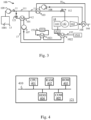
- FIG. 3 schematically illustrates the combined heating and cooling system 100 according to a third exemplary embodiment.
- the system 100 comprises the tank 13 storing the dihydrogen 1001, the main pipe 11 transporting the dihydrogen between the tank 13 and the combustion chamber 142 of the engine 14, and the bypass pipe 12.
- the system 100 further comprises the second closed circuit 18 comprising the third and fourth heat exchangers 103 and 104.
- the system comprises the first closed circuit 17, which comprises, successively in the direction of circulation of the first heat transfer fluid, the first heat exchanger 101, a first secondary heat exchanger 1021 and a second secondary heat exchanger 1022.
- each heat exchanger 1021, 1022 makes it possible to carry out a heat exchange between two fluids without mixing them, in other words to transfer heat from one fluid to the other fluid through an exchange surface.
- the second secondary heat exchanger 1022 makes it possible to carry out a second secondary heat exchange between the first heat transfer fluid and compressed air from the compressor 141 of the engine 14 and transported by a compressed air pipe 152.
- the second secondary heat exchange causes a transfer of heat from the compressed air to the first heat transfer fluid and thus makes it possible to cool the compressed air.
- Compressed air is used in an air conditioning system of the aircraft.
- the compressed air is compressed and heated in the compressor 141 of the engine 14.
- the flow of compressed air is regulated at the outlet of the compressor 141 by a system of valves 1521 and then sent through the second secondary heat exchanger 1022.
- the compressed air is transported to an air conditioning system 1522 where it is used to pressurize and air condition the cabin of the aircraft.
- the control unit When the measured oil temperature decreases, for example when the oil temperature decreases and falls below a third predefined threshold, the control unit sends a command to reduce the flow of dihydrogen 1001 to the flow controller 121.
- control unit determines whether the measured temperature of the oil is above the third predefined threshold. If so, the control unit sends a command to increase the flow of dihydrogen 1001 to the flow controller 121.
- FIG. 4 schematically illustrates an example of hardware architecture of an internal control unit of the flow controller 121.
- the internal control unit of the flow controller 121 then comprises, connected by a communication bus 410: a processor or CPU ("Central Processing Unit” in English) 401; a random access memory RAM ("Random Access Memory” in English) 402; a read only memory ROM ("Read Only Memory” in English) 403; a storage unit or a storage media reader, such as a hard disk HDD ("Hard Disk Drive” in English) 404; and a communication interface 405 for communicating with elements such as temperature sensors.
- a processor or CPU Central Processing Unit
- RAM Random Access Memory
- ROM Read Only Memory
- the processor 401 is capable of executing instructions loaded into the RAM 402 from the ROM 403, an external memory (not shown), a storage medium, or a communications network. When the control unit is powered on, the processor 401 is capable of reading instructions from the RAM 402 and executing them. These instructions form a computer program causing the processor 401 to implement some or all of the actions described herein in relation to the control unit.
- control unit of the flow controller 121 can be implemented in software form by the execution of a set of instructions by a programmable machine, such as a DSP (Digital Signal Processor) or a microcontroller, or in hardware form by a machine or a dedicated component, such as an FPGA (Field-Programmable Gate Array) or an ASIC (Application-Specific Integrated Circuit).
- a programmable machine such as a DSP (Digital Signal Processor) or a microcontroller
- FPGA Field-Programmable Gate Array
- ASIC Application-Specific Integrated Circuit
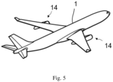
- FIG. 5 illustrates aircraft 1 equipped with the combined heating and cooling system.
Landscapes
- Engineering & Computer Science (AREA)
- Chemical & Material Sciences (AREA)
- Combustion & Propulsion (AREA)
- Aviation & Aerospace Engineering (AREA)
- Mechanical Engineering (AREA)
- General Engineering & Computer Science (AREA)
- Chemical Kinetics & Catalysis (AREA)
- General Chemical & Material Sciences (AREA)
- Oil, Petroleum & Natural Gas (AREA)
- Health & Medical Sciences (AREA)
- General Health & Medical Sciences (AREA)
- Pulmonology (AREA)
- Heat-Exchange Devices With Radiators And Conduit Assemblies (AREA)
- Loading And Unloading Of Fuel Tanks Or Ships (AREA)
Claims (14)
- Verfahren zur kombinierten Kühlung und Erwärmung in einem Flugzeug (1), wobei das Flugzeug ein Triebwerk (14) umfasst, das dazu ausgestaltet ist, Diwasserstoff (1001) als Treibstoff zu verwenden, wobei der Diwasserstoff (1001) in flüssiger Form in einem Tank (13) gespeichert wird und in dem Triebwerk (14) in gasförmiger Form verwendet wird, wobei das Triebwerk (14) ein Turboproptriebwerk ist, wobei der Diwasserstoff (1001) von dem Tank (13) bis zu dem Triebwerk (14) über eine Leitung, Hauptleitung (11) genannt, befördert wird, wobei das Verfahren ferner die Schritte umfasst:- Abzweigen, parallel zu einem vorgegebenen Abschnitt (111) der Hauptleitung (11), eines Teils des Stroms aus Diwasserstoff (1001) in eine Abzweigleitung (12) genannte Leitung,- Umwälzen, in einem ersten geschlossenen Kreislauf (17), eines ersten Wärmeträgerfluids,- Durchführen eines ersten Wärmeaustausches zwischen dem ersten Wärmeträgerfluid und dem Diwasserstoff (1001), der in der Abzweigleitung (12) zirkuliert, wobei das Verfahren dadurch gekennzeichnet ist, dass es den Schritt des Durchführens mindestens eines zweiten Wärmeaustausches, sekundärer Wärmeaustausch genannt, umfasst, wobei jeder sekundäre Wärmeaustausch zwischen dem ersten Wärmeträgerfluid und einem Fluid, das in dem Flugzeug verwendet wird, und gekühlt werden muss, Nutzfluid genannt, durchgeführt wird.
- Verfahren nach Anspruch 1, umfassend ferner die Schritte:- Umwälzen, in einem zweiten geschlossenen Kreislauf (18), eines zweiten Wärmeträgerfluids,- Durchführen eines dritten Wärmeaustausches zwischen dem zweiten Wärmeträgerfluid und dem Diwasserstoff (1001), der in einem Teil der Hauptleitung (11) zirkuliert, und- Durchführen eines vierten Wärmeaustausches zwischen dem zweiten Wärmeträgerfluid und einem Abgas, das aus einer Turbine (143) des Triebwerks (14) stammt.
- Verfahren nach Anspruch 2, wobei der dritte Wärmeaustausch stromab des vorgegebenen Abschnitts (111) der Hauptleitung (11) durchgeführt wird.
- Verfahren nach Anspruch 2, wobei der dritte Wärmeaustausch stromauf des vorgegebenen Abschnitts (111) der Hauptleitung (11) durchgeführt wird.
- Verfahren nach einem der Ansprüche 1 bis 4, wobei das erste Wärmeträgerfluid einen Betriebstemperaturbereich umfasst, der enger als der Betriebstemperaturbereich des zweiten Wärmeträgerfluids ist.
- Verfahren nach einem der Ansprüche 1 bis 5, wobei das Nutzfluid Öl ist oder Druckluft, die aus dem Triebwerk stammt und dazu bestimmt ist, in einem Klimatisierungssystem des Flugzeugs verwendet zu werden.
- Verfahren nach einem der Ansprüche 1 bis 5, umfassend einen ersten sekundären Wärmeaustausch zwischen dem ersten Wärmeträgerfluid und einem ersten Nutzfluid und einen zweiten sekundären Wärmeaustausch zwischen dem ersten Wärmeträgerfluid und einem zweiten Nutzfluid, wobei das erste Nutzfluid Öl ist und wobei das zweite Nutzfluid Druckluft ist, die aus dem Triebwerk stammt und dazu bestimmt ist, in einem Klimatisierungssystem des Flugzeugs verwendet zu werden.
- Verfahren nach einem der Ansprüche 1 bis 7, umfassend ferner das Durchführen einer Regelung des Stroms aus Diwasserstoff (1001), der in der Abzweigleitung (12) zirkuliert, gemäß einer Temperatur des Nutzfluids, die im Ausgang des sekundären Wärmeaustausches gemessen wird, den das Nutzfluid durchläuft.
- Verfahren nach einem der Ansprüche 1 bis 8, umfassend ferner das Durchführen einer Regelung des Stroms aus Diwasserstoff (1001), der in der Abzweigleitung (12) zirkuliert, gemäß einer Temperatur des ersten Wärmeträgerfluids, die im Eingang des ersten Wärmeaustausches gemessen wird.
- System (100) zur kombinierten Kühlung und Erwärmung in einem Flugzeug (1), wobei das Flugzeug ein Triebwerk (14) umfasst, das Diwasserstoff (1001) als Treibstoff verwendet, wobei der Diwasserstoff (1001) in flüssiger Form in einem Tank (13) gespeichert wird und in dem Triebwerk (14) in gasförmiger Form verwendet wird, wobei das Triebwerk (14) ein Turboproptriebwerk ist, wobei der Diwasserstoff (1001) von dem Tank (13) bis zu dem Triebwerk (14) über eine Leitung, Hauptleitung (11) genannt, befördert wird, wobei das System ferner umfasst:- eine Leitung, Abzweigleitung (12) genannt, die in Abzweigung in Bezug auf einen vorgegebenen Abschnitt (111) der Hauptleitung (11) montiert ist,- einen ersten geschlossenen Kreislauf (17), der dazu vorgesehen ist, ein erstes Wärmeträgerfluid zu enthalten,- einen ersten Zirkulator (107), der dazu vorgesehen ist, das erste Wärmeträgerfluid in dem ersten geschlossenen Kreislauf umzuwälzen,- einen ersten Wärmetauscher (101), der so installiert ist, dass er einen ersten Wärmeaustausch zwischen dem ersten Wärmeträgerfluid und dem Diwasserstoff (1001), der in der Abzweigleitung (12) zirkuliert, ermöglicht, wobei das System dadurch gekennzeichnet ist, dass es umfasst- einen zweiten Wärmetauscher (102), der so installiert ist, dass er mindestens einen zweiten Wärmeaustausch, sekundärer Wärmeaustausch genannt, ermöglicht, wobei jeder sekundäre Wärmeaustausch zwischen dem ersten Wärmeträgerfluid und einem Fluid, das in dem Flugzeug verwendet wird und gekühlt werden muss, Nutzfluid genannt, durchgeführt wird.
- System (100) nach dem vorhergehenden Anspruch, wobei der erste Zirkulator (107) einer Pumpe entspricht.
- System (100) nach einem der Ansprüche 10 und 11, umfassend ferner:- einen zweiten geschlossenen Kreislauf (18), der dazu vorgesehen ist, ein zweites Wärmeträgerfluid zu enthalten,- einen zweiten Zirkulator (108), der dazu vorgesehen ist, das zweite Wärmeträgerfluid in dem zweiten geschlossenen Kreislauf umzuwälzen,- einen dritten Wärmetauscher (103), der so installiert ist, dass er einen dritten Wärmeaustausch zwischen dem zweiten Wärmeträgerfluid und dem Diwasserstoff (1001), der in einem Teil der Hauptleitung (11) zirkuliert, ermöglicht,- einen vierten Wärmetauscher (104), der so installiert ist, dass er einen vierten Wärmeaustausch zwischen dem zweiten Wärmeträgerfluid und einem Abgas, das aus einer Turbine (143) des Triebwerks (14) stammt, ermöglicht.
- System (100) nach dem vorhergehenden Anspruch, wobei der zweite Zirkulator (108) einer Pumpe entspricht.
- Flugzeug (1), das mindestens ein System (100) nach einem der Ansprüche 10 bis 13 umfasst.
Applications Claiming Priority (1)
| Application Number | Priority Date | Filing Date | Title |
|---|---|---|---|
| FR2112637A FR3129661A1 (fr) | 2021-11-29 | 2021-11-29 | Systeme de chauffage de dihydrogene et de refroidissement de fluide combines pour aeronef, et aeronef comprenant un tel systeme |
Publications (2)
| Publication Number | Publication Date |
|---|---|
| EP4187071A1 EP4187071A1 (de) | 2023-05-31 |
| EP4187071B1 true EP4187071B1 (de) | 2024-09-11 |
Family
ID=80122389
Family Applications (1)
| Application Number | Title | Priority Date | Filing Date |
|---|---|---|---|
| EP22209957.4A Active EP4187071B1 (de) | 2021-11-29 | 2022-11-28 | Kombiniertes system zur erwärmung von wasserstoff und kühlung von flüssigkeit für ein flugzeug und flugzeug mit solch einem system |
Country Status (4)
| Country | Link |
|---|---|
| US (1) | US12234020B2 (de) |
| EP (1) | EP4187071B1 (de) |
| CN (1) | CN116181527A (de) |
| FR (1) | FR3129661A1 (de) |
Families Citing this family (3)
| Publication number | Priority date | Publication date | Assignee | Title |
|---|---|---|---|---|
| US20230406515A1 (en) * | 2022-05-17 | 2023-12-21 | Hamilton Sundstrand Corporation | Hydrogen-cooled environmental control system |
| US20260022665A1 (en) * | 2024-07-18 | 2026-01-22 | General Electric Company | Fuel thermal management systems and related methods |
| CN118833420B (zh) * | 2024-09-20 | 2024-12-06 | 常州贺斯特科技股份有限公司 | 飞行器液冷装置及其工作方法 |
Family Cites Families (10)
| Publication number | Priority date | Publication date | Assignee | Title |
|---|---|---|---|---|
| DE2413507A1 (de) * | 1974-03-20 | 1975-10-02 | Motoren Turbinen Union | Gasturbine fuer kryogenen kraftstoff |
| US4569195A (en) * | 1984-04-27 | 1986-02-11 | General Electric Company | Fluid injection gas turbine engine and method for operating |
| CN1259219C (zh) * | 2003-12-30 | 2006-06-14 | 上海交通大学 | 燃氢高速飞机的液氢燃料携带和换热系统 |
| US10054051B2 (en) * | 2014-04-01 | 2018-08-21 | The Boeing Company | Bleed air systems for use with aircraft and related methods |
| US20160160758A1 (en) * | 2014-12-08 | 2016-06-09 | United Technologies Corporation | Gas turbine engine nacelle anti-icing system |
| US11187156B2 (en) * | 2017-11-21 | 2021-11-30 | General Electric Company | Thermal management system |
| US11047307B2 (en) * | 2018-09-14 | 2021-06-29 | Raytheon Technologies Corporation | Hybrid expander cycle with intercooling and turbo-generator |
| US10989117B2 (en) * | 2018-09-14 | 2021-04-27 | Raytheon Technologies Corporation | Hybrid expander cycle with pre-compression cooling and turbo-generator |
| US20210340908A1 (en) * | 2020-05-01 | 2021-11-04 | Raytheon Technologies Corporation | Gas turbine engines having cryogenic fuel systems |
| PL4060173T3 (pl) * | 2021-03-17 | 2024-02-26 | Itp Engines Uk Ltd | Zespół napędowy statku powietrznego zawierający układ rekuperacyjny z obiegiem zamkniętym |
-
2021
- 2021-11-29 FR FR2112637A patent/FR3129661A1/fr not_active Ceased
-
2022
- 2022-11-23 US US17/993,158 patent/US12234020B2/en active Active
- 2022-11-28 EP EP22209957.4A patent/EP4187071B1/de active Active
- 2022-11-29 CN CN202211514325.2A patent/CN116181527A/zh active Pending
Also Published As
| Publication number | Publication date |
|---|---|
| US20230166847A1 (en) | 2023-06-01 |
| EP4187071A1 (de) | 2023-05-31 |
| CN116181527A (zh) | 2023-05-30 |
| US12234020B2 (en) | 2025-02-25 |
| FR3129661A1 (fr) | 2023-06-02 |
Similar Documents
| Publication | Publication Date | Title |
|---|---|---|
| EP4187071B1 (de) | Kombiniertes system zur erwärmung von wasserstoff und kühlung von flüssigkeit für ein flugzeug und flugzeug mit solch einem system | |
| EP4158169B1 (de) | Anlage zum erwärmen eines kryogenen kraftstoffs | |
| EP4158171B1 (de) | Kryogenes brennstoffzufuhrsystem für eine turbinenmotorbrennkammer | |
| CA2678657C (fr) | Systeme de refroidissement et de regulation en temperature d'equipements d'un ensemble propulsif d'aeronef | |
| EP1620637A2 (de) | System zum kühlen eines ausstattungsteils auf eine niedrige temperatur, wie zum beispiel eines teils einer kraftfahrzeugausstattung, und zugehörige wärmetauscher | |
| EP1706610B1 (de) | Vorrichtung zur steuerung der temperatur von in einem verbrennungsmotorfahrzeug zirkulierenden fluiden und von der vorrichtung verwendetes verfahren | |
| WO2013034829A9 (fr) | Circuits d'huile et de carburant dans une turbomachine et procédé de gestion d ' échanges thermiques | |
| EP4515091B1 (de) | Brennstoffkonditionierungssystem zur versorgung eines flugzeugturbinenmotors und verfahren zur versorgung eines turbinenmotors | |
| FR3113516A1 (fr) | Système de Gestion Thermique pour Refroidir des Charges Calorifiques Transitoires à Faible Consommation de Puissance | |
| FR3128488A1 (fr) | Système de conditionnement de carburant pour alimenter une turbomachine d’aéronef, aéronef et procédé d’utilisation | |
| FR2951228A1 (fr) | Procede et systeme de gestion d'echanges thermiques entre fluides dans une turbomachine | |
| WO2023072623A1 (fr) | Système de conditionnement de carburant pour alimenter une turbomachine d'aéronef, procédé d'alimentation d'une turbomachine | |
| WO2023208872A1 (fr) | Système de contrôle de la température d'un fluide caloporteur dans une boucle de circulation, procédé de contrôle de la température | |
| WO2021064319A1 (fr) | Système de traitement d'un gaz contenu dans une cuve de stockage et/ou de transport de gaz à l'état liquide et gazeux | |
| FR3096404A1 (fr) | Dispositif de régulation de la température d’au moins un élément d'un moteur thermique suralimenté | |
| EP3250810B1 (de) | Luftansaugsystem und ansaugluftwärmeverwaltungsverfahren | |
| FR2880067A1 (fr) | Installation de regulation thermique des gaz admis dans un moteur | |
| FR3132932A1 (fr) | Turbomachine pourvue d’un échangeur thermique hydrogène/air | |
| EP1819910B1 (de) | Niedrigtemperatur-ausrüstungskühlsystem für einen teil einer motorfahrzeugausrüstung und damit verbundene wärmetauscher | |
| EP4702225A1 (de) | System und verfahren zur kühlung eines flugzeugturbinenmotors | |
| EP3660415A1 (de) | Vorrichtung für die thermische regelung eines gebäudes, entsprechende anlage und entsprechendes verfahren | |
| WO2019193121A1 (fr) | Dispositif réversible de récupération d'énergie calorifique | |
| FR3091898A1 (fr) | Circuit de refroidissement d’un moteur thermique equipe d’un circuit recuperateur de chaleur |
Legal Events
| Date | Code | Title | Description |
|---|---|---|---|
| PUAI | Public reference made under article 153(3) epc to a published international application that has entered the european phase |
Free format text: ORIGINAL CODE: 0009012 |
|
| STAA | Information on the status of an ep patent application or granted ep patent |
Free format text: STATUS: THE APPLICATION HAS BEEN PUBLISHED |
|
| AK | Designated contracting states |
Kind code of ref document: A1 Designated state(s): AL AT BE BG CH CY CZ DE DK EE ES FI FR GB GR HR HU IE IS IT LI LT LU LV MC ME MK MT NL NO PL PT RO RS SE SI SK SM TR |
|
| STAA | Information on the status of an ep patent application or granted ep patent |
Free format text: STATUS: REQUEST FOR EXAMINATION WAS MADE |
|
| 17P | Request for examination filed |
Effective date: 20231123 |
|
| RBV | Designated contracting states (corrected) |
Designated state(s): AL AT BE BG CH CY CZ DE DK EE ES FI FR GB GR HR HU IE IS IT LI LT LU LV MC ME MK MT NL NO PL PT RO RS SE SI SK SM TR |
|
| GRAP | Despatch of communication of intention to grant a patent |
Free format text: ORIGINAL CODE: EPIDOSNIGR1 |
|
| STAA | Information on the status of an ep patent application or granted ep patent |
Free format text: STATUS: GRANT OF PATENT IS INTENDED |
|
| RIC1 | Information provided on ipc code assigned before grant |
Ipc: B64D 13/06 20060101ALN20240319BHEP Ipc: B64D 37/30 20060101ALI20240319BHEP Ipc: B64D 33/08 20060101ALI20240319BHEP Ipc: F02C 3/22 20060101ALI20240319BHEP Ipc: F02C 7/224 20060101ALI20240319BHEP Ipc: F02C 7/14 20060101AFI20240319BHEP |
|
| INTG | Intention to grant announced |
Effective date: 20240408 |
|
| GRAS | Grant fee paid |
Free format text: ORIGINAL CODE: EPIDOSNIGR3 |
|
| GRAA | (expected) grant |
Free format text: ORIGINAL CODE: 0009210 |
|
| STAA | Information on the status of an ep patent application or granted ep patent |
Free format text: STATUS: THE PATENT HAS BEEN GRANTED |
|
| AK | Designated contracting states |
Kind code of ref document: B1 Designated state(s): AL AT BE BG CH CY CZ DE DK EE ES FI FR GB GR HR HU IE IS IT LI LT LU LV MC ME MK MT NL NO PL PT RO RS SE SI SK SM TR |
|
| REG | Reference to a national code |
Ref country code: GB Ref legal event code: FG4D Free format text: NOT ENGLISH |
|
| REG | Reference to a national code |
Ref country code: CH Ref legal event code: EP |
|
| REG | Reference to a national code |
Ref country code: DE Ref legal event code: R096 Ref document number: 602022006036 Country of ref document: DE |
|
| REG | Reference to a national code |
Ref country code: IE Ref legal event code: FG4D Free format text: LANGUAGE OF EP DOCUMENT: FRENCH |
|
| REG | Reference to a national code |
Ref country code: LT Ref legal event code: MG9D |
|
| PG25 | Lapsed in a contracting state [announced via postgrant information from national office to epo] |
Ref country code: NO Free format text: LAPSE BECAUSE OF FAILURE TO SUBMIT A TRANSLATION OF THE DESCRIPTION OR TO PAY THE FEE WITHIN THE PRESCRIBED TIME-LIMIT Effective date: 20241211 |
|
| REG | Reference to a national code |
Ref country code: NL Ref legal event code: MP Effective date: 20240911 |
|
| PG25 | Lapsed in a contracting state [announced via postgrant information from national office to epo] |
Ref country code: GR Free format text: LAPSE BECAUSE OF FAILURE TO SUBMIT A TRANSLATION OF THE DESCRIPTION OR TO PAY THE FEE WITHIN THE PRESCRIBED TIME-LIMIT Effective date: 20241212 Ref country code: FI Free format text: LAPSE BECAUSE OF FAILURE TO SUBMIT A TRANSLATION OF THE DESCRIPTION OR TO PAY THE FEE WITHIN THE PRESCRIBED TIME-LIMIT Effective date: 20240911 |
|
| PG25 | Lapsed in a contracting state [announced via postgrant information from national office to epo] |
Ref country code: BG Free format text: LAPSE BECAUSE OF FAILURE TO SUBMIT A TRANSLATION OF THE DESCRIPTION OR TO PAY THE FEE WITHIN THE PRESCRIBED TIME-LIMIT Effective date: 20240911 |
|
| PG25 | Lapsed in a contracting state [announced via postgrant information from national office to epo] |
Ref country code: LV Free format text: LAPSE BECAUSE OF FAILURE TO SUBMIT A TRANSLATION OF THE DESCRIPTION OR TO PAY THE FEE WITHIN THE PRESCRIBED TIME-LIMIT Effective date: 20240911 |
|
| PG25 | Lapsed in a contracting state [announced via postgrant information from national office to epo] |
Ref country code: HR Free format text: LAPSE BECAUSE OF FAILURE TO SUBMIT A TRANSLATION OF THE DESCRIPTION OR TO PAY THE FEE WITHIN THE PRESCRIBED TIME-LIMIT Effective date: 20240911 |
|
| PG25 | Lapsed in a contracting state [announced via postgrant information from national office to epo] |
Ref country code: RS Free format text: LAPSE BECAUSE OF FAILURE TO SUBMIT A TRANSLATION OF THE DESCRIPTION OR TO PAY THE FEE WITHIN THE PRESCRIBED TIME-LIMIT Effective date: 20241211 Ref country code: ES Free format text: LAPSE BECAUSE OF FAILURE TO SUBMIT A TRANSLATION OF THE DESCRIPTION OR TO PAY THE FEE WITHIN THE PRESCRIBED TIME-LIMIT Effective date: 20240911 |
|
| PG25 | Lapsed in a contracting state [announced via postgrant information from national office to epo] |
Ref country code: RS Free format text: LAPSE BECAUSE OF FAILURE TO SUBMIT A TRANSLATION OF THE DESCRIPTION OR TO PAY THE FEE WITHIN THE PRESCRIBED TIME-LIMIT Effective date: 20241211 Ref country code: NO Free format text: LAPSE BECAUSE OF FAILURE TO SUBMIT A TRANSLATION OF THE DESCRIPTION OR TO PAY THE FEE WITHIN THE PRESCRIBED TIME-LIMIT Effective date: 20241211 Ref country code: LV Free format text: LAPSE BECAUSE OF FAILURE TO SUBMIT A TRANSLATION OF THE DESCRIPTION OR TO PAY THE FEE WITHIN THE PRESCRIBED TIME-LIMIT Effective date: 20240911 Ref country code: HR Free format text: LAPSE BECAUSE OF FAILURE TO SUBMIT A TRANSLATION OF THE DESCRIPTION OR TO PAY THE FEE WITHIN THE PRESCRIBED TIME-LIMIT Effective date: 20240911 Ref country code: GR Free format text: LAPSE BECAUSE OF FAILURE TO SUBMIT A TRANSLATION OF THE DESCRIPTION OR TO PAY THE FEE WITHIN THE PRESCRIBED TIME-LIMIT Effective date: 20241212 Ref country code: FI Free format text: LAPSE BECAUSE OF FAILURE TO SUBMIT A TRANSLATION OF THE DESCRIPTION OR TO PAY THE FEE WITHIN THE PRESCRIBED TIME-LIMIT Effective date: 20240911 Ref country code: ES Free format text: LAPSE BECAUSE OF FAILURE TO SUBMIT A TRANSLATION OF THE DESCRIPTION OR TO PAY THE FEE WITHIN THE PRESCRIBED TIME-LIMIT Effective date: 20240911 Ref country code: BG Free format text: LAPSE BECAUSE OF FAILURE TO SUBMIT A TRANSLATION OF THE DESCRIPTION OR TO PAY THE FEE WITHIN THE PRESCRIBED TIME-LIMIT Effective date: 20240911 |
|
| REG | Reference to a national code |
Ref country code: AT Ref legal event code: MK05 Ref document number: 1722857 Country of ref document: AT Kind code of ref document: T Effective date: 20240911 |
|
| PG25 | Lapsed in a contracting state [announced via postgrant information from national office to epo] |
Ref country code: NL Free format text: LAPSE BECAUSE OF FAILURE TO SUBMIT A TRANSLATION OF THE DESCRIPTION OR TO PAY THE FEE WITHIN THE PRESCRIBED TIME-LIMIT Effective date: 20240911 |
|
| PG25 | Lapsed in a contracting state [announced via postgrant information from national office to epo] |
Ref country code: PT Free format text: LAPSE BECAUSE OF FAILURE TO SUBMIT A TRANSLATION OF THE DESCRIPTION OR TO PAY THE FEE WITHIN THE PRESCRIBED TIME-LIMIT Effective date: 20250113 Ref country code: IS Free format text: LAPSE BECAUSE OF FAILURE TO SUBMIT A TRANSLATION OF THE DESCRIPTION OR TO PAY THE FEE WITHIN THE PRESCRIBED TIME-LIMIT Effective date: 20250111 |
|
| PG25 | Lapsed in a contracting state [announced via postgrant information from national office to epo] |
Ref country code: RO Free format text: LAPSE BECAUSE OF FAILURE TO SUBMIT A TRANSLATION OF THE DESCRIPTION OR TO PAY THE FEE WITHIN THE PRESCRIBED TIME-LIMIT Effective date: 20240911 Ref country code: SM Free format text: LAPSE BECAUSE OF FAILURE TO SUBMIT A TRANSLATION OF THE DESCRIPTION OR TO PAY THE FEE WITHIN THE PRESCRIBED TIME-LIMIT Effective date: 20240911 |
|
| PG25 | Lapsed in a contracting state [announced via postgrant information from national office to epo] |
Ref country code: AT Free format text: LAPSE BECAUSE OF FAILURE TO SUBMIT A TRANSLATION OF THE DESCRIPTION OR TO PAY THE FEE WITHIN THE PRESCRIBED TIME-LIMIT Effective date: 20240911 Ref country code: EE Free format text: LAPSE BECAUSE OF FAILURE TO SUBMIT A TRANSLATION OF THE DESCRIPTION OR TO PAY THE FEE WITHIN THE PRESCRIBED TIME-LIMIT Effective date: 20240911 |
|
| PG25 | Lapsed in a contracting state [announced via postgrant information from national office to epo] |
Ref country code: CZ Free format text: LAPSE BECAUSE OF FAILURE TO SUBMIT A TRANSLATION OF THE DESCRIPTION OR TO PAY THE FEE WITHIN THE PRESCRIBED TIME-LIMIT Effective date: 20240911 Ref country code: PL Free format text: LAPSE BECAUSE OF FAILURE TO SUBMIT A TRANSLATION OF THE DESCRIPTION OR TO PAY THE FEE WITHIN THE PRESCRIBED TIME-LIMIT Effective date: 20240911 |
|
| PG25 | Lapsed in a contracting state [announced via postgrant information from national office to epo] |
Ref country code: IT Free format text: LAPSE BECAUSE OF FAILURE TO SUBMIT A TRANSLATION OF THE DESCRIPTION OR TO PAY THE FEE WITHIN THE PRESCRIBED TIME-LIMIT Effective date: 20240911 Ref country code: SK Free format text: LAPSE BECAUSE OF FAILURE TO SUBMIT A TRANSLATION OF THE DESCRIPTION OR TO PAY THE FEE WITHIN THE PRESCRIBED TIME-LIMIT Effective date: 20240911 |
|
| REG | Reference to a national code |
Ref country code: DE Ref legal event code: R097 Ref document number: 602022006036 Country of ref document: DE |
|
| PG25 | Lapsed in a contracting state [announced via postgrant information from national office to epo] |
Ref country code: MC Free format text: LAPSE BECAUSE OF FAILURE TO SUBMIT A TRANSLATION OF THE DESCRIPTION OR TO PAY THE FEE WITHIN THE PRESCRIBED TIME-LIMIT Effective date: 20240911 |
|
| PG25 | Lapsed in a contracting state [announced via postgrant information from national office to epo] |
Ref country code: DK Free format text: LAPSE BECAUSE OF FAILURE TO SUBMIT A TRANSLATION OF THE DESCRIPTION OR TO PAY THE FEE WITHIN THE PRESCRIBED TIME-LIMIT Effective date: 20240911 |
|
| PG25 | Lapsed in a contracting state [announced via postgrant information from national office to epo] |
Ref country code: LU Free format text: LAPSE BECAUSE OF NON-PAYMENT OF DUE FEES Effective date: 20241128 |
|
| PLBE | No opposition filed within time limit |
Free format text: ORIGINAL CODE: 0009261 |
|
| STAA | Information on the status of an ep patent application or granted ep patent |
Free format text: STATUS: NO OPPOSITION FILED WITHIN TIME LIMIT |
|
| 26N | No opposition filed |
Effective date: 20250612 |
|
| REG | Reference to a national code |
Ref country code: BE Ref legal event code: MM Effective date: 20241130 |
|
| PG25 | Lapsed in a contracting state [announced via postgrant information from national office to epo] |
Ref country code: SE Free format text: LAPSE BECAUSE OF FAILURE TO SUBMIT A TRANSLATION OF THE DESCRIPTION OR TO PAY THE FEE WITHIN THE PRESCRIBED TIME-LIMIT Effective date: 20240911 |
|
| PG25 | Lapsed in a contracting state [announced via postgrant information from national office to epo] |
Ref country code: BE Free format text: LAPSE BECAUSE OF NON-PAYMENT OF DUE FEES Effective date: 20241130 |
|
| PG25 | Lapsed in a contracting state [announced via postgrant information from national office to epo] |
Ref country code: IE Free format text: LAPSE BECAUSE OF NON-PAYMENT OF DUE FEES Effective date: 20241128 |
|
| PGFP | Annual fee paid to national office [announced via postgrant information from national office to epo] |
Ref country code: DE Payment date: 20251119 Year of fee payment: 4 |
|
| PGFP | Annual fee paid to national office [announced via postgrant information from national office to epo] |
Ref country code: FR Payment date: 20251126 Year of fee payment: 4 |
|
| PG25 | Lapsed in a contracting state [announced via postgrant information from national office to epo] |
Ref country code: HU Free format text: LAPSE BECAUSE OF FAILURE TO SUBMIT A TRANSLATION OF THE DESCRIPTION OR TO PAY THE FEE WITHIN THE PRESCRIBED TIME-LIMIT; INVALID AB INITIO Effective date: 20221128 |
|
| PG25 | Lapsed in a contracting state [announced via postgrant information from national office to epo] |
Ref country code: CY Free format text: LAPSE BECAUSE OF FAILURE TO SUBMIT A TRANSLATION OF THE DESCRIPTION OR TO PAY THE FEE WITHIN THE PRESCRIBED TIME-LIMIT; INVALID AB INITIO Effective date: 20221128 |