EP4049606A1 - Elektrochirurgisches handgerät und kontaktkörper für elektrochirurgisches handgerät - Google Patents
Elektrochirurgisches handgerät und kontaktkörper für elektrochirurgisches handgerät Download PDFInfo
- Publication number
- EP4049606A1 EP4049606A1 EP22156696.1A EP22156696A EP4049606A1 EP 4049606 A1 EP4049606 A1 EP 4049606A1 EP 22156696 A EP22156696 A EP 22156696A EP 4049606 A1 EP4049606 A1 EP 4049606A1
- Authority
- EP
- European Patent Office
- Prior art keywords
- contact body
- contact
- receptacle
- held device
- electrode
- Prior art date
- Legal status (The legal status is an assumption and is not a legal conclusion. Google has not performed a legal analysis and makes no representation as to the accuracy of the status listed.)
- Pending
Links
Images

Classifications
-
- A—HUMAN NECESSITIES
- A61—MEDICAL OR VETERINARY SCIENCE; HYGIENE
- A61B—DIAGNOSIS; SURGERY; IDENTIFICATION
- A61B18/00—Surgical instruments, devices or methods for transferring non-mechanical forms of energy to or from the body
- A61B18/04—Surgical instruments, devices or methods for transferring non-mechanical forms of energy to or from the body by heating
- A61B18/12—Surgical instruments, devices or methods for transferring non-mechanical forms of energy to or from the body by heating by passing a current through the tissue to be heated, e.g. high-frequency current
- A61B18/14—Probes or electrodes therefor
- A61B18/1485—Probes or electrodes therefor having a short rigid shaft for accessing the inner body through natural openings
-
- A—HUMAN NECESSITIES
- A61—MEDICAL OR VETERINARY SCIENCE; HYGIENE
- A61B—DIAGNOSIS; SURGERY; IDENTIFICATION
- A61B90/00—Instruments, implements or accessories specially adapted for surgery or diagnosis and not covered by any of the groups A61B1/00 - A61B50/00, e.g. for luxation treatment or for protecting wound edges
- A61B90/70—Cleaning devices specially adapted for surgical instruments
-
- A—HUMAN NECESSITIES
- A61—MEDICAL OR VETERINARY SCIENCE; HYGIENE
- A61B—DIAGNOSIS; SURGERY; IDENTIFICATION
- A61B18/00—Surgical instruments, devices or methods for transferring non-mechanical forms of energy to or from the body
- A61B18/04—Surgical instruments, devices or methods for transferring non-mechanical forms of energy to or from the body by heating
- A61B18/12—Surgical instruments, devices or methods for transferring non-mechanical forms of energy to or from the body by heating by passing a current through the tissue to be heated, e.g. high-frequency current
- A61B18/14—Probes or electrodes therefor
- A61B18/149—Probes or electrodes therefor bow shaped or with rotatable body at cantilever end, e.g. for resectoscopes, or coagulating rollers
-
- A—HUMAN NECESSITIES
- A61—MEDICAL OR VETERINARY SCIENCE; HYGIENE
- A61B—DIAGNOSIS; SURGERY; IDENTIFICATION
- A61B18/00—Surgical instruments, devices or methods for transferring non-mechanical forms of energy to or from the body
- A61B2018/00053—Mechanical features of the instrument of device
- A61B2018/00059—Material properties
- A61B2018/00071—Electrical conductivity
- A61B2018/00083—Electrical conductivity low, i.e. electrically insulating
-
- A—HUMAN NECESSITIES
- A61—MEDICAL OR VETERINARY SCIENCE; HYGIENE
- A61B—DIAGNOSIS; SURGERY; IDENTIFICATION
- A61B18/00—Surgical instruments, devices or methods for transferring non-mechanical forms of energy to or from the body
- A61B2018/00053—Mechanical features of the instrument of device
- A61B2018/00172—Connectors and adapters therefor
- A61B2018/00178—Electrical connectors
-
- A—HUMAN NECESSITIES
- A61—MEDICAL OR VETERINARY SCIENCE; HYGIENE
- A61B—DIAGNOSIS; SURGERY; IDENTIFICATION
- A61B18/00—Surgical instruments, devices or methods for transferring non-mechanical forms of energy to or from the body
- A61B2018/00053—Mechanical features of the instrument of device
- A61B2018/00184—Moving parts
- A61B2018/00196—Moving parts reciprocating lengthwise
-
- A—HUMAN NECESSITIES
- A61—MEDICAL OR VETERINARY SCIENCE; HYGIENE
- A61B—DIAGNOSIS; SURGERY; IDENTIFICATION
- A61B18/00—Surgical instruments, devices or methods for transferring non-mechanical forms of energy to or from the body
- A61B2018/00315—Surgical instruments, devices or methods for transferring non-mechanical forms of energy to or from the body for treatment of particular body parts
- A61B2018/00505—Urinary tract
- A61B2018/00517—Urinary bladder or urethra
-
- A—HUMAN NECESSITIES
- A61—MEDICAL OR VETERINARY SCIENCE; HYGIENE
- A61B—DIAGNOSIS; SURGERY; IDENTIFICATION
- A61B18/00—Surgical instruments, devices or methods for transferring non-mechanical forms of energy to or from the body
- A61B2018/00315—Surgical instruments, devices or methods for transferring non-mechanical forms of energy to or from the body for treatment of particular body parts
- A61B2018/00547—Prostate
-
- A—HUMAN NECESSITIES
- A61—MEDICAL OR VETERINARY SCIENCE; HYGIENE
- A61B—DIAGNOSIS; SURGERY; IDENTIFICATION
- A61B18/00—Surgical instruments, devices or methods for transferring non-mechanical forms of energy to or from the body
- A61B2018/00315—Surgical instruments, devices or methods for transferring non-mechanical forms of energy to or from the body for treatment of particular body parts
- A61B2018/00559—Female reproductive organs
-
- A—HUMAN NECESSITIES
- A61—MEDICAL OR VETERINARY SCIENCE; HYGIENE
- A61B—DIAGNOSIS; SURGERY; IDENTIFICATION
- A61B18/00—Surgical instruments, devices or methods for transferring non-mechanical forms of energy to or from the body
- A61B2018/00571—Surgical instruments, devices or methods for transferring non-mechanical forms of energy to or from the body for achieving a particular surgical effect
- A61B2018/00601—Cutting
-
- A—HUMAN NECESSITIES
- A61—MEDICAL OR VETERINARY SCIENCE; HYGIENE
- A61B—DIAGNOSIS; SURGERY; IDENTIFICATION
- A61B18/00—Surgical instruments, devices or methods for transferring non-mechanical forms of energy to or from the body
- A61B2018/0091—Handpieces of the surgical instrument or device
-
- A—HUMAN NECESSITIES
- A61—MEDICAL OR VETERINARY SCIENCE; HYGIENE
- A61B—DIAGNOSIS; SURGERY; IDENTIFICATION
- A61B18/00—Surgical instruments, devices or methods for transferring non-mechanical forms of energy to or from the body
- A61B2018/00982—Surgical instruments, devices or methods for transferring non-mechanical forms of energy to or from the body combined with or comprising means for visual or photographic inspections inside the body, e.g. endoscopes
Definitions
- the invention relates to a contact body for electrosurgical hand-held devices according to the preamble of claim 1.
- the invention also relates to an electrosurgical hand-held device according to claim 11.
- Electrosurgical hand-held devices such as resectoscopes, are mainly used for endoscopic applications in urology or gynecology, and there preferably for treating the bladder, uterus or prostate.
- the field of application of these instruments is not limited to these areas of the human body, but also includes the treatment of other organs in the human abdomen.
- the generic instruments described here such as resectoscopes, have a conveyor as standard.
- the resectoscope with an elongated shaft is inserted through an opening in the patient's body.
- Various medical instruments for treating and/or examining the patient can be arranged in this shaft tube.
- an electrode that can be subjected to high-frequency alternating current and that is positioned at a distal end of an electrode carrier can be guided through the shaft.
- the electrode carrier with the electrode is relative to the Shaft tube and along a shaft axis displaceable, so that this is manipulated by moving the electrode along or through the tissue.
- the proximal end of the electrode carrier is coupled to the transporter.
- the cutting movement of the electrode is made possible by this handling of the transport dog.
- the conveyor has a movably mounted contact body, which is also referred to as a carriage.
- the electrode carrier can be mechanically releasably coupled to this contact body with an electrical contact.
- the electrode carrier or the electrode can also be supplied with electrical energy via this mechanical connection.
- the contact body has a blind hole-like bore or opening, into which an electrical contact of the electrode carrier can be guided for the detachable connection.
- This opening or this blind hole is designed in such a way that the HF voltage can be applied via an adjacent plug connector.
- a plug is usually plugged into the socket, which in turn can be connected to an HF generator via a line or a cable.
- the actuation or the longitudinal displacement of the conveyor is carried out by an operator.
- the conveyor is assigned a handle unit with a first handle and a second handle.
- the operator grips the first handle and the second handle, which can have a finger unit or a thumb ring.
- the first handle means may be attached to a fixed main body of the conveyor.
- the second grip means may be attached to the contact body.
- a spring tension force of a spring which in the case of the generic feeder is usually designed as a leaf spring or as a torsion spring.
- This spring is attached at one end to the contact body or the carriage and at the other end to an end body or an optical guide plate of a reinforcing tube.
- the type of springs or the type of actuation of this spring mechanism depends on whether the conveyor is an active or a passive conveyor. While the spring is designed as a compression spring in an active conveyor, it is designed as a tension spring in a passive conveyor.
- the electrode is usually cut by a retracting movement of the feed dog.
- the electrode In the case of the active transporter, the electrode is pulled back against the spring force of the spring (in the proximal direction).
- the electrode With the passive carrier on the other hand, the electrode is first advanced against the spring force (in the distal direction) and then cuts through the tissue during the return movement (in the proximal direction) caused by the release of the spring.
- An optic can also be guided through the shaft of the instruments described here.
- the rod-like or shaft-like optics are guided from the proximal end through a reinforcement tube of the transporter into the shaft.
- Exemplary embodiments are known in which the optics are guided as a rod lens system or as a glass fiber from a proximal end through the shaft to the distal end.
- the distal end of the optics is aimed directly at the area to be operated on or the effective site of the electrode.
- the surgeon can observe the treatment through an eyepiece or a camera.
- the at least one electrical contact of the electrode system is then connected to the contact body and then pushed through or into the shaft.
- the contact body By actuating the second grip means relative to the first grip means, the contact body can be moved back and forth along the shaft axis together with the electrode carrier via a reinforcement tube.
- the contact body is movably arranged on the reinforcement tube.
- the contact body has a corresponding bore for the reinforcement tube parallel to the shaft axis. This hole is dimensioned in such a way that the contact body or the carriage can be easily pushed over the reinforcement tube.
- the invention is based on the object of creating an electrosurgical hand-held device and a contact body that can be cleaned in a particularly simple, thorough and time-efficient manner.
- the contact body for an electrosurgical hand-held device has at least one receptacle, which is designed as a continuous bore through the contact body.
- This continuous receptacle which extends from one end face of the contact body to an opposite end face of the contact body, can be cleaned particularly thoroughly and easily.
- This channel-like bore through the entire contact body can be flushed particularly thoroughly with a cleaning medium in such a way that neither particles nor residual liquid remain in the receptacle.
- a receptacle selected in this way for the electrical contact can also be dried particularly well, so that after the cleaning process the interior of the receptacle is processed without leaving any residue.
- the contact body is preferably also made for the contact body to have two receptacles, each of which is in the form of through bores through the entire contact body.
- a contact body designed in this way is designed to receive or electrically contact an electrode carrier with two electrical contacts. These electrical contacts, which in each case lead to the distally arranged electrode, in particular through electrode casing tubes, can be an active contact and a return contact or the active electrode and the return electrode.
- This symmetry not only makes the design of the hand-held device and the electron carrier particularly compact and space-saving, but also the shape of the contact body.
- the parallel arrangement of the receptacles to a shaft axis and thus possibly also to a bore for receiving a reinforcing tube for the optics, the coupling or decoupling of the electrode carrier with the contact body turns out to be particularly advantageous.
- This relative arrangement means that not only reliable contacting but also easy-to-use contacting can be implemented.
- the two contacts can be inserted into and removed from the receptacles with just a small amount of force.
- the mechanical coupling of the contacts in the Contact body strong enough to withstand forces that occur parallel or transverse to the longitudinal axis during treatment.
- the invention provides that at least one receptacle of an inner wall has an electrical contact which can be connected to a generator via a connector, in particular via a socket, and an electrical connection, the connector preferably being integrated into the contact body.
- the plug connector can be arranged perpendicularly or parallel to the receptacle in the contact body.
- the plug connector is preferably guided from below through the contact body to the channel-like receptacle.
- it can be particularly advantageous if necessary to contact both receptacles using appropriate external plugs. This contacting of the two receptacles allows a particularly defined and stable electrical potential to be generated at the ends of the electrode carrier.
- the two plugs or plug-in connections are guided into the at least one receptacle of the contact body from the proximal end face.
- a cable is led out of the contact body, on which a plug connector is arranged.
- the electrical contact within the at least one receptacle is designed as a cylindrical, hollow-cylindrical or ring-shaped electrical contact, preferably as a lamellar contact or spiral spring contact.
- These types of contact allow the electrical contacting of the contacts of the electrode carrier to be produced particularly reliably.
- the receptacles can be assigned a different form of contact for electrical contacting.
- a particularly advantageous exemplary embodiment of the invention can also provide that the distance of the at least one contact from an end face of the contact body, in particular from an outlet of the at least one receptacle, is at least 2 mm, preferably at least 4 mm, in particular at least 6 mm.
- Another preferred exemplary embodiment of the invention can provide for a mechanical latching means to extend into at least one receptacle for the detachable coupling of at least one proximal end of the electrode carrier, the latching means being operable, preferably lockable and/or releasable, via a handling means, in particular a spring-loaded button , is.
- a handling means in particular a spring-loaded button
- the locking means is locked with the locking means to an electrical To avoid short circuits between the two contacts.
- the corresponding proximal area on the electrode carrier, on which the latching is carried out has a deformation in cross section, such as a notch or a recess, in which the latching means can engage in a latching manner.
- This locking connection is designed in such a way that it can be carried out by the operator with one hand.
- the bore of the at least one receptacle is funnel-shaped at a distal exit, in particular that an end face of the contact body has a funnel-like countersink around the bore of the at least one receptacle.
- This funnel-like shape of the entry area of the receptacle makes it easier to insert the contacts of the electrode carrier into the receptacles. It is sufficient that when the electrode carrier is brought together with the contact body, the two proximal ends of the electrode carrier are guided into the funnels. The sloping shape of the inside walls of the funnel then leads the contacts directly into the receptacles. This makes it easier to contact the electrode carrier, particularly during the operation.
- a seal in particular a fluid seal, is arranged in the receptacles or in the bores in front of or behind the electrical contacts.
- This seal can prevent rinsing liquid from flowing out of the shaft through the receptacle of the contact body during the treatment and possibly leading to an electrical short circuit.
- This seal keeps the liquid out of the receptacle, at least for the most part.
- This seal is particularly preferably arranged directly at the distal end of the receptacles.
- plastic in particular PTFE
- PTFE is particularly advantageous for the contact body due to the material properties, such as low flow resistance, high electrical resistance, smooth surface and good workability.
- the contact body can be produced from another fluoropolymer such as PFA.
- PEEK has also proven advantageous. These materials are also particularly suitable because they can be cleaned particularly thoroughly.
- an electrosurgical Hand-held device such as a resectoscope
- an electrode carrier which has an electrode at a distal end and at least one electrical contact at a proximal end
- At least one component, in particular a stop, of the hand-held device which is arranged on the contact body in the proximal or distal direction or abuts on the contact body, consists of an electrically non-conductive material or an electrically non-conductive layer, preferably one coating.
- This can prevent rinsing liquid from passing through the channel-like receptacle during the treatment of the patient and creating an electrical connection between the contact of the electrode carrier and, for example, the returning electrical potential.
- the holder can be lengthened, e.g. by having the proximal end of the holder not emerge from the proximal end face but, for example, from the underside.
- an electrically conductive component, in particular a stop, of the hand-held device is separated from the contact body by an air gap, preferably an exit from at least one channel-like receptacle of the contact body, with the air gap having a width of at least 1 mm, in particular at least 2 mm.
- a stop surface is spaced radially from the outlet of the at least one channel-like receptacle of the contact body.
- a distance between the electrode and a distal end of a shaft, in particular the optics or an electrode cladding tube, is less than a distance between a proximal end of the electrode carrier and a proximal end face of the contact body and/or is less than a distance between an electrical contact and at least one end face of the contact body.
- FIG 1 A possible embodiment of an electrosurgical hand-held device, namely a resectoscope 10, is highly schematized in FIG 1 shown.
- the resectoscope 10 has a conveyor 11 to which an elongated, tubular shaft 12 can be fastened.
- This shaft 12 is in the 1 shown hatched and is attached to a main body 13 of the conveyor 11 with a proximal end.
- the conveyor 11 has a handle unit 14 .
- This handle unit 14 has a first handle 15 and a second handle 16. While the first handle 15 is fixed to the main body 13, the second handle 16 is associated with a contact body 17 in the embodiment of the conveyor 11 shown here. It is conceivable that the second handle 16 is screwed to the contact body 17 .
- the contact body 17 has a corresponding bore 31 in a wall.
- the contact body 17 is slidably guided on a tube-like optics guide 18 .
- the contact body 17 has a bore 19, the diameter of which is slightly larger than a diameter of the optics guide 18. Since the contact body 17 can be moved back and forth on the optics guide 18 along a longitudinal direction of the resectoscope 10 or a longitudinal axis of the shaft 12, the contact body 17 is also referred to as a carriage.
- an optics guide plate 20 is fixed to a proximal end of the optics guide 18 .
- the tubular optics guide 18 extends through the optics guide plate 20 so that the optics guide 18 is accessible from the proximal end.
- the second handle means 16 or the contact body 17 are connected to the optics guide plate 20 via a spring element 21 .
- this spring element 21 can be a tension spring or a compression spring.
- a tubular inner tube 22 extends in the distal direction. This inner tube 22 can also extend through the main body 13 in the proximal direction and be connected to the optics guide 18 .
- An electrode carrier 23 extends parallel to the inner tube 22. This electrode carrier 23 is guided through the main body 13 and is mechanically detachably coupled to the contact body 17 with at least one proximal contact.
- the electrode carrier 23 has an electrode 24 at a distal end. An electrical HF voltage can be applied to this electrode 24 .
- the diseased tissue can be manipulated or cut by means of thermal energy generated at the electrode 24 . To do this, the operator moves the second grip means 16, which has a thumb ring 25, relative to the first grip means 15. To stabilize the electrode carrier 23, it can be guided on the inner tube 22 by guides 26.
- a receptacle 27 of the proximal contact of the electrode carrier 23 can be electrically contacted in order to apply the HF voltage to the electrode 24 .
- the contact body 17 has at least one plug connector 29, in particular a socket. This connector 29 is in electrical contact with at least a part of an inner wall of the receptacle 27.
- the contact body 17 can be connected to an HF generator via a cable using a plug (not shown here).
- a rod-like optic is guided through the inner tube 22 or optic guide 18 to carry out the intervention.
- a distal end of this optic which is not visible here, is directed in the direction of the electrode 24 so that the operator can see the manipulation of the tissue.
- This optic can be a rod lens system or a glass fiber.
- At the proximal end of the optics is, as in the 1 shown, an eyepiece 30 or a camera.
- a contact body 17 In the 2 a possible embodiment of a contact body 17 is shown.
- This contact body 17 can be designed either in the form of a ring or in the manner of a cuboid.
- PTFE has proven to be a particularly preferred material for this contact body 17 .
- other fluoropolymers with similar material properties are also conceivable.
- One of the reasons why PTFE is particularly suitable is that it has particularly low sliding friction.
- the contact body 17 has a continuous bore 19 through which the optics guide 18 extends when the conveyor 11 is in the assembled state extends. When the transporter 11 is actuated, the contact body 17 is guided along the optics guide 18 . In order for the surgeon to be able to carry out this movement without great exertion, the sliding resistance must be kept low.
- the contact body 17 has a bore 31 in which the second grip means 16 can be mounted.
- this bore 31 is not absolutely necessary. Rather, it is conceivable that the second grip means 16 can also be connected to the contact body 17 in a different way.
- a channel-like receptacle 27 extends through the contact body 17, specifically from one end face 32 to the other end face 33 of the contact body 17.
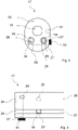
- the exemplary embodiment of the contact body 17 shown here has two of these channel-like receptacles 27, 28 ( Figure 3, Figure 4 ). These two receptacles 27, 28 are aligned parallel to each other and parallel to the bore 19.
- the receptacles 27, 28 are located in the same plane in the contact body 17 and are spaced apart from one another in such a way that the two proximal ends of the electrode carrier 23 can be guided into the receptacles 27, 28.
- These two proximal ends of the electrode carrier 23 each have an electrical contact, namely, for example, an active contact and a return contact.
- These contacts of the electrode carrier 23 are not only fixed mechanically in the receptacles 27, 28, but are also subjected to a predefined electrical potential.
- the ends of the receptacles 27, 28 on the end face 32 each have a funnel-like depression or a funnel 34. This funnel 34 considerably simplifies the coupling of the electrode carrier 23 to the contact body 17 .
- the inner walls of the receptacles 27, 28 have electrical contacts. These contacts can be lamellar contacts or spiral spring contacts, for example. So that these contacts within the receptacles 27, 28 can be supplied with electrical energy, both receptacles 27, 28 are each connected to a connector 29, in particular a two-pin coaxial connector or a corresponding socket for a coaxial connector.
- This connector 29, such as in the 2 and 3 shown, are introduced from below through the contact body 17 to the receptacles 27, 28. It is equally conceivable that the connector 29 extend parallel to the receptacles 27, 28 through the contact body 17.
- To the Commissioning of the resectoscope 10 are to be added to the connector 29 plug, which are connected to an electrical conductor or a cable with the generator, not shown.
- a latching means 36 is assigned to at least one receptacle 28.
- This latching means 36 is connected to a knob 35 via a shaft-like pin 37 ( 4 ).
- the locking means 36 is spring-loaded and can be actuated by the button 35 .
- the latching means 36 is pressed out of the receptacle 28, so that the electrode carrier 23 with the two contacts can be inserted into the contact body 17.
- the contact guided into the receptacle 28 has a recess into which the latching means 36 engages, as a result of which the mechanical coupling is established. It is equally conceivable that when the electrode carrier 23 is inserted into the receptacle 28, the latching means 36 is pushed back and latches into the corresponding recess.
- the latching means 36 is preferably associated with only one receptacle 27 , 28 in order to avoid the risk of an electrical short circuit between the two receptacles 27 , 28 .
- the continuous, channel-like receptacles 27, 28 can be cleaned particularly well.
- a flushing liquid can thus be flushed through the contact body 17 from one end face 32 to the other end face 33 in a simple and effective manner.
- the disadvantage described above, that particles in particular remain in a blind hole even after cleaning, can be completely ruled out here. Subsequent drying of the contact body 17 is also easily possible.
- components of the resectoscope 10 which face an end face 32, 33 of the contact body 17 can consist of an electrically insulating material or have a corresponding coating. This prevents electrical contact being made with a further electrical potential, for example by rinsing liquid that could pass through the receptacles 27, 28 during the operation.
- the contact body 17 is dimensioned such that a distance between a contact part of the electrode or the contact 38 and one of the end faces 32, 33 is greater than the distance between the electrode 24 and the nearest conductive component, in particular the optics or an electrode cladding tube return potential. Thereby it can be ensured that the plasma ignites at the electrode 24 and not in the contact body 17.
Landscapes
- Health & Medical Sciences (AREA)
- Surgery (AREA)
- Life Sciences & Earth Sciences (AREA)
- Engineering & Computer Science (AREA)
- Heart & Thoracic Surgery (AREA)
- Animal Behavior & Ethology (AREA)
- Veterinary Medicine (AREA)
- Biomedical Technology (AREA)
- Nuclear Medicine, Radiotherapy & Molecular Imaging (AREA)
- Medical Informatics (AREA)
- Molecular Biology (AREA)
- Public Health (AREA)
- General Health & Medical Sciences (AREA)
- Physics & Mathematics (AREA)
- Plasma & Fusion (AREA)
- Otolaryngology (AREA)
- Pathology (AREA)
- Oral & Maxillofacial Surgery (AREA)
- Surgical Instruments (AREA)
Abstract
Description
- Die Erfindung betrifft einen Kontaktkörper für elektrochirurgische Handgeräte gemäß dem Oberbegriff des Anspruchs 1. Außerdem betrifft die Erfindung ein elektrochirurgisches Handgerät gemäß dem Anspruch 11.
- Elektrochirurgische Handgeräte, wie beispielsweise Resektoskope, werden hauptsächlich für endoskopische Anwendungen in der Urologie oder in der Gynäkologie eingesetzt und dort vorzugsweise für die Behandlung im Bereich der Blase, Gebärmutter oder der Prostata. Das Einsatzgebiet dieser Instrumente ist jedoch nicht auf diese Bereiche des menschlichen Körpers beschränkt, sondern umfasst vielmehr auch die Behandlung weiterer Organe im menschlichen Unterleib.
- Die hier beschriebenen gattungsgemäßen Instrumente, wie beispielsweise Resektoskope, weisen standardmäßig einen Transporteur auf. Zur Behandlung des erkrankten Gewebes wird das Resektoskop mit einem langgestreckten Schaft durch eine Öffnung in den Körper des Patienten eingeführt. In diesem Schaftrohr können verschiedene medizinische Instrumente zur Behandlung und/oder zur Untersuchung des Patienten angeordnet sein. Zum Beispiel kann etwa für die Hochfrequenzchirurgie eine mit hochfrequentem Wechselstrom beaufschlagbare Elektrode, die an einem distalen Ende eines Elektrodenträgers positioniert ist, durch den Schaft geführt werden. Für die Manipulation bzw. das Schneiden des Gewebes ist der Elektrodenträger mit der Elektrode relativ zum Schaftrohr sowie entlang einer Schaftachse verschiebbar, so dass durch Entlangbewegen der Elektrode an oder durch das Gewebe dieses manipuliert wird.
- Der Elektrodenträger ist des Weiteren mit seinem proximalen Ende an den Transporteur gekoppelt. Durch diese Handhabung des Transporteurs wird die Schneidbewegung der Elektrode ermöglicht. Der Transporteur weist einen bewegbar gelagerten Kontaktkörper auf, der auch als Schlitten bezeichnet wird. An diesem Kontaktkörper kann der Elektrodenträger mit einem elektrischen Kontakt mechanisch lösbar gekoppelt sein. Über diese mechanische Verbindung ist der Elektrodenträger bzw. die Elektrode auch mit elektrischer Energie versorgbar. Dazu weist der Kontaktkörper eine sacklochartige Bohrung bzw. Öffnung auf, in die ein elektrischer Kontakt des Elektrodenträgers für die lösbare Verbindung führbar ist. Diese Öffnung bzw. dieses Sackloch ist derart ausgebildet, dass über einen angrenzenden Steckverbinder die HF-Spannung beaufschlagbar ist. Dazu wird üblicherweise ein Stecker in die Buchse gesteckt, der wiederum über eine Leitung bzw. ein Kabel mit einem HF-Generator verbindbar ist.
- Die Betätigung bzw. der Längsverschub des Transporteurs, also auch der Elektrode, wird durch einen Operateur ausgeführt. Dazu ist dem Transporteur eine Griffeinheit mit einem ersten Griffmittel und einem zweiten Griffmittel zugeordnet. Der Operateur erfasst zum Betätigen des Transporteurs das erste Griffmittel, als auch das zweite Griffmittel, das eine Fingereinheit bzw. einen Daumenring aufweisen kann. Das erste Griffmittel kann an einem feststehenden Hauptkörper des Transporteurs befestigt sein. Das zweite Griffmittel kann an dem Kontaktkörper befestigt sein.
- Die Bewegung des Transporteurs erfolgt gegen eine Federspannkraft einer Feder, die beim gattungsgemäßen Transporteur üblicherweise als Blattfeder oder als Schenkelfeder ausgebildet ist. Diese Feder ist mit einem Ende an dem Kontaktkörper bzw. dem Schlitten und mit dem anderen Ende an einem Endkörper bzw. einer Optikführungsplatte eines Verstärkungsrohres befestigt. Die Art der Federn bzw. die Art der Betätigung dieses Federmechanismus richtet sich danach, ob es sich bei dem Transporteur um einen aktiven oder einen passiven Transporteur handelt. Während die Feder bei einem aktiven Transporteur als Druckfeder ausgebildet ist, ist sie bei einem passiven Transporteur als Zugfeder ausgebildet.
- Üblicherweise erfolgt das Schneiden der Elektrode durch eine rückziehende Bewegung des Transporteurs. Beim aktiven Transporteur wird dazu die Elektrode gegen die Federkraft der Feder zurückgezogen (in proximale Richtung). Beim passiven Transporteur hingegen wird die Elektrode zunächst entgegen der Federkraft vorgeschoben (in distale Richtung), um dann bei der durch die Entlastung der Feder hervorgerufenen Rückbewegung (in proximale Richtung) durch das Gewebe zu schneiden.
- Durch den Schaft der hier beschriebenen Instrumente ist außerdem eine Optik führbar. Die stabartige bzw. schaftartige Optik wird von dem proximalen Ende her durch ein Verstärkungsrohr des Transporteurs in den Schaft geführt. Es sind Ausführungsbeispiele bekannt, bei denen die Optik als Stablinsensystem oder als Glasfaser von einem proximalen Ende durch den Schaft zum distalen Ende geführt wird. Das distale Ende der Optik ist direkt auf den zu operierenden Bereich bzw. den Wirkort der Elektrode gerichtet. Am proximalen Ende der Optik kann der Operateur durch ein Okular oder eine Kamera die Behandlung beobachten.
- Der mindestens eine elektrische Kontakt des Elektrodensystems wird dann mit dem Kontaktkörper verbunden und sodann durch bzw. in den Schafft geschoben. Durch Betätigung des zweiten Griffmittels relativ zu dem ersten Griffmittel lässt sich so der Kontaktkörper zusammen mit dem Elektrodenträger über ein Verstärkungsrohr entlang der Schaftachse vor und zurück bewegen.
- Am proximalen Ende des Verstärkungsrohres ist dieses mit einer Optikführungsplatte verschweißt. Der Kontaktkörper ist beweglich auf dem Verstärkungsrohr angeordnet. Dazu weist der Kontaktkörper eine entsprechende Bohrung für das Verstärkungsrohr parallel zu der Schaftachse auf. Diese Bohrung ist derart bemessen, dass sich der Kontaktkörper bzw. der Schlitten leicht über das Verstärkungsrohr schieben lässt.
- Als besonders nachteilig hat sich die Reinigbarkeit der Kontaktaufnahme bzw. des Sackloches für den Kontakt des Elektrodenträgers erwiesen. Insbesondere durch den geringen Lochdurchmesser als auch Verwendung von elektrischen Tulpenkontakten innerhalb des Sacklochs gestaltet sich die Reinigung als sehr schwer. Selbst durch eine maschinelle Reinigung kann nicht garantiert werden, dass der notwendige Reinigungsgrad erreicht wird. Insbesondere Rückstände von Flüssigkeiten oder Partikel, die während der Behandlung oder auch während des Reinigungsprozesses in die Aufnahme gelangen, lassen sich nur schwer oder gar nicht entfernen. Neben dem Problem der ungenügenden Aufbereitung bzw. Reinigung können sowohl in der Aufnahme verbleibende Partikel als auch Flüssigkeit zu Kontaktproblemen zwischen dem Elektrodenträger und dem Kontakt in der Aufnahme führen.
- Davon ausgehend liegt der Erfindung die Aufgabe zu Grunde, ein elektrochirurgisches Handgerät sowie einen Kontaktkörper zu schaffen, der besonders einfach, gründlich sowie zeiteffizient reinigbar ist.
- Ein Kontaktkörper zur Lösung dieser Aufgabe weist die Merkmale des Anspruchs 1 auf. Demnach ist es vorgesehen, dass der Kontaktkörper für ein elektrochirurgisches Handgerät mindestens eine Aufnahme aufweist, die als durchgehende Bohrung durch den Kontaktkörper ausgebildet ist. Diese durchgehende, sich von einer Stirnseite des Kontaktkörpers zu einer gegenüberliegenden Stirnseite des Kontaktkörpers erschreckende, Aufnahme lässt sich besonders gründlich sowie einfach reinigen. Diese kanalartige Bohrung durch den gesamten Kontaktkörper kann besonders gründlich mit einem Reinigungsmedium durchgespült werden und zwar derart, dass weder Partikel noch eine Restflüssigkeit in der Aufnahme verbleibt. Eine derart ausgewählte Aufnahme für den elektrischen Kontakt lässt sich auch besonders gut trocknen, sodass nach dem Reinigungsprozess der Innenraum der Aufnahme rückstandslos aufbereitet ist.
- Vorzugsweise ist es weiter vorgesehen, dass der Kontaktkörper zwei Aufnahmen aufweist, die jeweils als durchgehende Bohrungen durch den gesamten Kontaktkörper ausgebildet sind. Ein derart ausgebildeter Kontaktkörper ist ausgelegt für die Aufnahme bzw. elektrische Kontaktierung eines Elektrodenträgers mit zwei elektrischen Kontakten. Bei diesen elektrischen Kontakten, die jeweils, insbesondere durch Elektrodenhüllrohre, zu der distal angeordneten Elektrode führen, kann es sich um einen Aktiv-Kontakt und einen Return-Kontakt bzw. um die Aktiv-Elektrode und die Return-Elektrode handeln.
- Bevorzugterweise ist es vorgesehen, dass die beiden Aufnahmen für die beiden vorgenannten elektrischen Kontakte parallel zueinander sowie parallel zu einer Längsachse des Handgerätes bzw. des Elektrodenträgers ausgerichtet sind und in einer gemeinsamen Ebene liegen. Durch diese Symmetrie gestaltet sich nicht nur die Bauform des Handgerätes und des Elektronenträgers als besonders kompakt und raumsparend sondern auch die Form des Kontaktkörpers. Insbesondere die parallele Anordnung der Aufnahmen zu einer Schaftachse und somit gegebenenfalls auch zu einer Bohrung zur Aufnahme eines Verstärkungsrohres für die Optik, gestaltet sich das Koppeln bzw. das Entkoppeln des Elektrodenträgers mit dem Kontaktkörper als besonders vorteilhaft. So kann durch diese relative Anordnung nicht nur eine verlässliche Kontaktierung sondern auch eine einfach zu bedienende Kontaktierung realisiert werden. Bereits durch geringe Kraftausübung lassen sich die beiden Kontakte in die Aufnahmen einführen als auch wieder entnehmen. Gleichermaßen ist die mechanische Kopplung der Kontakte in dem Kontaktkörper ausreichend stark, um auch Kräften, die während der Behandlung parallel oder quer zur Längsachse auftreten, standzuhalten.
- Insbesondere sieht es die Erfindung vor, dass mindestens eine Aufnahme einer Innenwandung einen elektrischen Kontakt aufweist, der über einen Steckverbinder, insbesondere über eine Steckerbuchse, und eine elektrische Verbindung mit einem Generator verbindbar ist, wobei der Steckverbinder vorzugsweise in den Kontaktkörper integriert ist. Dabei kann der Steckverbinder senkrecht oder parallel zu der Aufnahme in dem Kontaktkörper angeordnet sein. Vorzugsweise wird der Steckverbinder von unten durch den Kontaktkörper hindurch an die kanalartige Aufnahme herangeführt. Zusätzlich kann es besonders vorteilhaft sein, gegebenenfalls beide Aufnahmen durch entsprechende externe Stecker zu kontaktieren. Durch diese Kontaktierung der beiden Aufnahmen lässt sich ein besonders definiertes sowie stabiles elektrisches Potenzial an den Elektrodenträgerenden erzeugen. Gleichermaßen ist denkbar, dass die beiden Stecker bzw. Steckverbindungen von der proximalen Stirnseite aus in die mindestens eine Aufnahme des Kontaktkörpers geführt werden. Alternativ ist es außerdem denkbar, dass ein Kabel aus dem Kontaktkörper herausgeführt wird, an dem ein Steckverbinder angeordnet ist.
- Weiter kann es erfindungsgemäß vorgesehen sein, dass der elektrische Kontakt innerhalb der mindestens einen Aufnahme als zylinderförmiger, hohlzylinder- oder ringförmiger elektrischer Kontakt, vorzugsweise als Lamellenkontakt oder Spiralfederkontakt, ausgebildet ist. Durch diese Kontaktarten lässt sich die elektrische Kontaktierung der Kontakte des Elektrodenträgers besonders zuverlässig herstellen. Darüber hinaus ist es auch denkbar, dass den Aufnahmen eine andere Kontaktform zur elektrischen Kontaktierung zugeordnet ist. Ein besonders vorteilhaftes Ausführungsbeispiel der Erfindung kann es weiter vorsehen, dass ein Abstand des mindestens einen Kontaktes zu einer Stirnseite des Kontaktkörpers, insbesondere zu einem Austritt der mindestens einen Aufnahme, mindestens 2 mm, bevorzugst mindestens 4 mm, insbesondere mindestens 6 mm, beträgt.
- Ein weiteres bevorzugtes Ausführungsbeispiel der Erfindung kann es vorgesehen, dass sich in mindestens eine Aufnahme ein mechanisches Rastmittel erstreckt zur lösbaren Kopplung mindestens eines proximalen Endes des Elektrodenträgers, wobei das Rastmittel über ein Handhabungsmittel, insbesondere einen federvorgespannten Knopf, betätigbar, vorzugsweise arretierbar und/oder lösbar, ist. Vorzugsweise wird nur einer der beiden Kontakte des Elektrodenträgers mit dem Rastmittel arretiert, um einen elektrischen Kurzschluss zwischen den beiden Kontakten zu vermeiden. Es ist denkbar, dass der entsprechende proximale Bereich an dem Elektrodenträger, an dem die Rastung vorgenommen wird, eine Verformung im Querschnitt, wie beispielsweise eine Kerbe oder eine Ausnehmung aufweist, in die das Rastmittel rastend eingreifen kann. Diese Rastverbindung ist derart ausgebildet, dass sie einhändig von dem Operateur durchführbar.
- Darüber hinaus kann eine vorteilhafte Weiterbildung darin gesehen werden, dass die Bohrung der mindestens einen Aufnahme an einem distalen Ausgang trichterartig ausgeführt ist, insbesondere dass eine Stirnseite des Kontaktkörpers um die Bohrung der mindestens einen Aufnahme eine trichterartige Senkung aufweist. Durch diese trichterartige Form des Eingangsbereichs der Aufnahme wird das Einführen der Kontakte des Elektrodenträgers in die Aufnahmen erleichtert. Dabei ist es ausreichend, dass beim Zusammenführen des Elektrodenträgers mit dem Kontaktkörper die beiden proximalen Enden des Elektrodenträgers in die Trichter geführt werden. Die schräge Form der Trichterinnenwände führen die Kontakte dann direkt in die Aufnahmen. Dies erleichtert die Kontaktierung des Elektrodenträgers insbesondere während der Operation.
- Weiter kann es erfindungsgemäß vorgesehen sein, dass in den Aufnahmen bzw. in den Bohrungen vor oder hinter den elektrischen Kontakten eine Dichtung, insbesondere eine Fluiddichtung, angeordnet ist. Durch diese Dichtung kann vermieden werden, dass während der Behandlung Spülflüssigkeit aus dem Schaft durch die Aufnahme des Kontaktkörpers fließt und gegebenenfalls zu einem elektrischen Kurzschluss führt. Durch diese Dichtung wird die Flüssigkeit wenigstens größtenteils aus der Aufnahme herausgehalten. Besonders bevorzugt ist diese Dichtung direkt am distalen Ende der Aufnahmen angeordnet.
- Es hat sich herausgestellt, dass Kunststoff, insbesondere PTFE, für den Kontaktkörper aufgrund der Materialeigenschaften wie beispielsweise geringer Geleitswiderstand, hoher elektrischer Widerstand, glatte Oberfläche sowie gute Bearbeitbarkeit besonders vorteilhaft ist. Gleichermaßen ist es jedoch auch denkbar, dass der Kontaktkörper aus einem anderen Fluorpolymer wie beispielsweise PFA herstellbar ist. Auch PEEK hat sich als vorteilhaft erwiesen. Diese Materialien eignen sich auch deshalb besonders gut, da sie besonders gründlich reinigbar sind.
- Eine weitere Lösung der eingangs genannten Aufgabe wird durch die Merkmale des Anspruchs 11 beschrieben. Demnach ist es vorgesehen, dass ein elektrochirurgisches Handgerät, wie beispielsweise ein Resektoskop, mit einem Elektrodenträger, der an einem distalen Ende eine Elektrode und an einem proximalen Ende mindestens einen elektrischen Kontakt aufweist, einen Kontaktkörper nach mindestens einem der Ansprüche 1-10 aufweist, in dem das mindestens eine proximale Ende des Elektrodenträgers kontaktierbar ist.
- Bevorzugterweise ist es vorgesehen, dass wenigstens eine Komponente, insbesondere ein Anschlag, des Handgerätes, der in proximale oder distale Richtung an den Kontaktkörper angeordnet ist oder an den Kontaktkörper anschlägt, aus einem elektrisch nicht leitenden Material besteht oder eine elektrische nicht leitende Schicht, vorzugsweise eine Beschichtung, aufweist. Dadurch kann verhindert werden, dass Spülflüssigkeit, während der Behandlung des Patienten durch die kanalartige Aufnahme tritt und eine elektrische Verbindung zwischen dem Kontakt des Elektrodenträgers und beispielsweise dem rückleitenden, elektrischen Potential erzeugt. Als Alternative ist eine Verlängerung der Aufnahme möglich, indem z.B. das proximale Ende der Aufnahme nicht an der proximalen Stirnseite sondern z.B. an der Unterseite austritt.
- Weiter ist es denkbar, dass eine elektrisch leitfähige Komponente, insbesondere ein Anschlag, des Handgerätes durch einen Luftspalt von dem Kontaktkörper, vorzugsweise einem Austritt mindestens einer kanalartigen Aufnahme des Kontaktkörpers, getrennt ist, wobei der Luftspalt eine Breite von mindestens 1 mm, insbesondere mindestens 2 mm, aufweist. Beispielsweise ist es denkbar, dass eine Anschlagsfläche radial von dem Austritt der mindestens einen kanalartigen Aufnahme des Kontaktkörpers beabstandet ist.
- Darüber hinaus ist es vorzuweise vorgesehen, dass ein Abstand zwischen der Elektrode und einem distalen Ende eines Schaftes, insbesondere der Optik oder einem Elektrodenhüllrohr, geringer ist als ein Abstand zwischen einem proximalen Ende des Elektrodenträgers und einer proximalen Stirnseite des Kontaktkörpers und/oder geringer ist als ein Abstand zwischen einem elektrischen Kontakt und wenigstens einer Stirnseite des Kontaktkörpers. Dadurch soll sichergestellt werden, dass während der Behandlung ein Plasma zwischen der Elektrode und der Neutralelektrode zündet und nicht im Kontaktkörper zwischen dem proximalen Ende des Elektrodenträgers und der proximalen Stirnseite des Kontaktkörpers.
- Ein bevorzugtes Ausführungsbeispiel der Erfindung wird im Folgenden anhand der Zeichnung näher erläutert. In dieser zeigen:
- Fig. 1
- eine schematische Darstellung eines Resektoskopes,
- Fig. 2
- eine Seitenansicht eines Kontaktkörpers,
- Fig. 3
- eine Sicht auf eine Stirnseite des Kontaktkörpers gemäß
Fig. 2 , und - Fig. 4
- ein Schnitt durch den Kontaktkörper gemäß
Fig. 2 . - Ein mögliches Ausführungsbeispiel eines elektrochirurgischen Handgerätes, nämlich eines Resektoskopes 10, ist stark schematisiert in der
Fig. 1 dargestellt. Das Resektoskop 10 weist einen Transporteur 11 auf, an dem ein langgestreckter, rohrartiger Schaft 12 befestigbar ist. Dieser Schaft 12 ist in derFig. 1 schraffiert dargestellt und ist mit einem proximalen Ende an einem Hauptkörper 13 des Transporteurs 11 befestigt. - Der Transporteur 11 weist neben dem Hauptkörper 13 eine Griffeinheit 14 auf. Diese Griffeinheit 14 verfügt über ein erstes Griffmittel 15 und ein zweites Griffmittel 16. Während das erste Griffmittel 15 fest an dem Hauptkörper 13 angeordnet ist, ist bei dem hier dargestellten Ausführungsbeispiel des Transporteurs 11 das zweite Griffmittel 16 einem Kontaktkörper 17 zugeordnet. Dabei ist es denkbar, dass das zweite Griffmittel 16 an dem Kontaktkörper 17 festgeschraubt ist. Dazu weist der Kontaktkörper 17 in einer Wandung eine entsprechende Bohrung 31 auf.
- Der Kontaktkörper 17 wird gleitend auf einer rohrartigen Optikführung 18 geführt. Dazu weist der Kontaktkörper 17 eine Bohrung 19 auf, deren Durchmesser geringfügig größer ist als ein Durchmesser der Optikführung 18. Da sich der Kontaktkörper 17 auf der Optikführung 18 entlang einer Längsrichtung des Resektoskops 10 bzw. einer Längsachse des Schaftes 12 hin und her bewegen lässt, wird der Kontaktkörper 17 auch als Schlitten bezeichnet.
- Während die Optikführung 18 mit einem distalen Ende mit dem Hauptkörper 13 oder einem Innenrohr 22 verbunden ist, ist an einem proximalen Ende der Optikführung 18 eine Optikführungsplatte 20 befestigt. Die rohrartige Optikführung 18 erstreckt sich durch die Optikführungsplatte 20, sodass die Optikführung 18 von proximal aus zugänglich ist.
- Das zweite Griffmittel 16 bzw. der Kontaktkörper 17 sind über ein Federelement 21 mit der Optikführungsplatte 20 verbunden. Bei diesem Federelement 21 kann es sich je nach Bauart des Transporteurs 11 um eine Zugfeder oder eine Druckfeder handeln. Ausgehend von dem Hauptkörper 13 erstreckt sich ein rohrartiges Innenrohr 22 in distale Richtung. Dieses Innenrohr 22 kann sich auch in proximale Richtung durch den Hauptkörper 13 erstrecken und mit der Optikführung 18 verbunden werden.
- Parallel zu dem Innenrohr 22 erstreckt sich ein Elektrodenträger 23. Dieser Elektrodenträger 23 wird durch den Hauptkörper 13 geführt und ist mit wenigstens einem proximalen Kontakt mechanisch mit dem Kontaktkörper 17 lösbar gekoppelt. An einem distalen Ende weist der Elektrodenträger 23 eine Elektrode 24 auf. Diese Elektrode 24 ist mit einer elektrischen HF-Spannung beaufschlagbar. Mittels sich an der Elektrode 24 bildende thermische Energie lässt sich das erkrankte Gewebe manipulieren bzw. schneiden. Dazu bewegt der Operateur das einen Daumenring 25 aufweisende zweite Griffmittel 16 relativ zu dem ersten Griffmittel 15. Zur Stabilisierung des Elektrodenträgers 23 kann dieses an dem Innenrohr 22 durch Führungen 26 geführt werden.
- Für die Beaufschlagung der Elektrode 24 mit der HF-Spannung lässt sich eine Aufnahme 27 des proximalen Kontaktes des Elektrodenträgers 23 elektrisch kontaktieren. Dazu weist der Kontaktkörper 17 mindestens einen Steckverbinder 29, insbesondere eine Steckerbuchse, auf. Dieser der Steckverbinder 29 befindet sich im elektrischen Kontakt mit wenigstens einem Teil einer Innenwandung der Aufnahme 27. Über einen hier nicht dargestellten Stecker lässt sich so der Kontaktkörper 17 über ein Kabel mit einem HF-Generator verbinden.
- Für die Durchführung des Eingriffs wird durch das Innenrohr 22 bzw. Optikführung 18 eine stabartige Optik geführt. Ein hier nicht sichtbares distales Ende dieser Optik ist in Richtung der Elektrode 24 gerichtet, damit der Operateur die Manipulation des Gewebes im Blick hat. Bei dieser Optik kann es sich um ein Stablinsensystem oder um eine Glasfaser handeln. Am proximalen Ende der Optik befindet sich, wie in der
Fig. 1 dargestellt, ein Okular 30 oder eine Kamera. - In der
Fig. 2 ist ein mögliches Ausführungsbeispiel eines Kontaktkörpers 17 dargestellt. Dieser Kontaktkörper 17 kann sowohl ringartig als auch quaderartig ausgebildet sein. Als besonders bevorzugtes Material für diesen Kontaktkörper 17 hat sich PTFE erwiesen. Allerdings sind auch andere Fluorpolymere mit ähnlichen Materialeigenschaften denkbar. PTFE bietet sich unter anderem deswegen an, da es eine besonders geringe Gleitreibung aufweist. Der Kontaktkörper 17 weist nämlich eine durchgängige Bohrung 19 auf, durch die sich im zusammengebauten Zustand des Transporteurs 11 die Optikführung 18 erstreckt. Bei der Betätigung des Transporteurs 11 wird der Kontaktkörper 17 entlang der Optikführung 18 geführt. Damit dieses von dem Operateur durchgeführte Entlangführen ohne größere Kraftanstrengung durchführbar ist, gilt es den Gleitwiderstand gering zu halten. - An einer Außenwandung weist der Kontaktkörper 17 eine Bohrung 31 auf, in die das zweite Griffmittel 16 lagerbar ist. Diese Bohrung 31 ist allerdings nicht zwingend erforderlich. Vielmehr ist denkbar, dass das zweite Griffmittel 16 auch auf eine andere Art und Weise mit dem Kontaktkörper 17 verbunden werden kann.
- Erfindungsgemäß erstreckt sich durch den Kontaktkörper 17 eine kanalartige Aufnahme 27 und zwar von einer Stirnseite 32 zu der anderen Stirnseite 33 des Kontaktkörpers 17. Das hier dargestellte Ausführungsbeispiel des Kontaktkörpers 17 weist zwei dieser kanalartigen Aufnahmen 27, 28 auf (
Fig. 3, Fig. 4 ). Diese beiden Aufnahmen 27, 28 sind parallel zueinander sowie parallel zu der Bohrung 19 ausgerichtet. Die Aufnahmen 27, 28 befinden sich in dem Kontaktkörper 17 in einer gleichen Ebene und sind derart voneinander beabstandet, dass die beiden proximalen Enden des Elektrodenträgers 23 in die Aufnahmen 27, 28 führbar sind. Diese beiden proximalen Enden des Elektrodenträgers 23 weisen jeweils einen elektrischen Kontakt auf, nämlich beispielsweise einen Aktiv-Kontakt und einen Return-Kontakt. - In den Aufnahmen 27, 28 werden diese Kontakte des Elektrodenträgers 23 nicht nur mechanisch fixiert sondern auch mit einem vordefinierten elektrischen Potenzial beaufschlagt. Für ein leichteres Einführen der Kontakte in die Aufnahmen 27, 28 weisen die Enden der Aufnahmen 27, 28 an der Stirnseite 32 jeweils eine trichterartige Senkung bzw. einen Trichter 34 auf. Durch diesen Trichter 34 wird das Koppeln des Elektrodenträgers 23 mit dem Kontaktkörper 17 erheblich vereinfacht.
- Die Innenwandungen der Aufnahmen 27, 28 weisen elektrische Kontakte auf. Bei diesen Kontakten kann es sich beispielsweise um Lamellenkontakte oder Spiralfederkontakte handeln. Damit diese Kontakte innerhalb der Aufnahmen 27, 28 mit elektrischer Energie beaufschlagbar sind, sind beide Aufnahmen 27, 28 mit jeweils einem Steckverbinder 29, insbesondere einem zweipoligen Koaxial-Stecker bzw. einer entsprechende Buchse für einen Koaxial-Stecker, verbunden. Diese Steckverbinder 29 können, wie beispielsweise in den
Fig. 2 und3 dargestellt, von unten durch den Kontaktkörper 17 an die Aufnahmen 27, 28 herangeführt werden. Gleichermaßen ist es denkbar, dass sich der Steckverbinder 29 parallel zu den Aufnahmen 27, 28 durch den Kontaktkörper 17 erstrecken. Zur Inbetriebnahme des Resektoskopes 10 sind in den Steckverbinder 29 Stecker zu fügen, die mit einem elektrischen Leiter bzw. einem Kabel mit dem nicht dargestellten Generator verbunden sind. - Um den Elektrodenträger 23 nicht nur elektrisch in dem Kontaktkörper 17 zu kontaktieren, sondern auch um die mechanische Arretierung zu dem Kontaktkörper 17 herzustellen, ist wenigstens einer Aufnahme 28 ein Rastmittel 36 zugeordnet. Dieses Rastmittel 36 ist über einen schaftartigen Stift 37 mit einem Knopf 35 verbunden (
Fig. 4 ). Das Rastmittel 36 ist federvorgespannt und durch den Knopf 35 betätigbar. Durch die Betätigung des Knopfes 35 wird das Rastmittel 36 aus der Aufnahme 28 heraus gedrückt, sodass der Elektrodenträger 23 mit den beiden Kontakten in den Kontaktkörper 17 einführbar ist. Der in die Aufnahme 28 geführte Kontakt weist eine Ausnehmung auf, in die das Rastmittel 36 einrastet, wodurch die mechanische Kopplung hergestellt ist. Es ist gleichermaßen denkbar, dass beim Einführen des Elektrodenträgers 23 in die Aufnahme 28 das Rastmittel 36 zurückgedrückt wird und in die entsprechende Ausnehmung einrastet. - Vorzugsweise ist das Rastmittel 36 nur einer Aufnahme 27, 28 zugeordnet, um die Gefahr eines elektrischen Kurzschlusses zwischen den beiden Aufnahmen 27, 28 zu vermeiden.
- Die durchgängigen, kanalartig ausgebildeten Aufnahmen 27, 28 lassen sich besonders gut reinigen. So lässt sich eine Spülflüssigkeit auf eine einfache sowie effektive Art und Weise von einer Stirnseite 32 zu der anderen Stirnseite 33 durch den Kontaktkörper 17 hindurchspülen. Der oben beschriebene Nachteil, dass in einem Sackloch insbesondere Partikel auch nach der Reinigung verbleiben, kann hier komplett ausgeschlossen werden. Auch ein anschließendes Trocknen des Kontaktkörpers 17 ist ohne weiteres möglich.
- Um einen Kriechstrom oder einen elektrischen Durchschlag zu verhindern, können Komponenten des Resektoskopes 10, welche einer Stirnseite 32, 33 des Kontaktkörpers 17 zugewandt sind, aus einem elektrisch isolierenden Material bestehen oder eine entsprechende Beschichtung aufweisen. Dadurch wird verhindert, dass beispielsweise durch Spülflüssigkeit, die während der Operation durch die Aufnahmen 27, 28 treten könnte, ein elektrischer Kontakt zu einem weiteren elektrischen Potenzial hergestellt wird.
- Der Kontaktkörper 17 ist derart bemessen, dass ein Abstand zwischen einem Kontaktteil der Elektrode bzw. dem Kontakt 38 und einer der Stirnseiten 32, 33 größer ist als der Abstand zwischen der Elektrode 24 und der nächstgelegenen leitfähigen Komponente, insbesondere der Optik oder einem Elektrodenhüllrohr, auf Return-Potential. Dadurch kann sichergestellt werden, dass das Plasma an der Elektrode 24 zündet und nicht in dem Kontaktkörper 17.
Bezugszeichenliste 10 Resektoskop 29 Steckverbinder 11 Transporteur 30 Okular 12 Schaft 31 Bohrung 13 Hauptkörper 32 Stirnseite 14 Griffeinheit 33 Stirnseite 15 erstes Griffmittel 34 Trichter 16 zweites Griffmittel 35 Knopf 17 Kontaktkörper 36 Rastmittel 18 Optikführung 37 Stift 19 Bohrung 38 elektrischer Kontakt 20 Optikführungsplatte 21 Federelement 22 Innenrohr 23 Elektrodenträger 24 Elektrode 25 Daumenring 26 Führung 27 Aufnahme 28 Aufnahme
Claims (14)
- Kontaktkörper (17) für ein elektrochirurgisches Handgerät, insbesondere Resektoskop (10), mit mindestens einer Aufnahme (27, 28) für ein mindestens einen elektrischen Kontakt aufweisendes proximales Ende eines Elektrodenträgers (23) des Handgerätes, wobei der Kontakt in der Aufnahme (27, 28) mechanisch sowie elektrisch koppelbar ist, dadurch gekennzeichnet, dass die mindestens eine Aufnahme (27, 28) als eine durchgehende Bohrung durch den Kontaktkörper (17) ausgebildet ist.
- Kontaktkörper (17) nach Anspruch 1, gekennzeichnet durch zwei Aufnahmen (27, 28), die jeweils als durchgehende Bohrung durch den Kontaktkörper (17) ausgebildet sind.
- Kontaktkörper (17) nach Anspruch 2, dadurch gekennzeichnet, dass die beiden Aufnahmen (27, 28) parallel zueinander sowie parallel zu einer Längsachse des Handgerätes ausgerichtet sind und in einer gemeinsamen Ebene liegen.
- Kontaktkörper (17) nach einem der vorhergehenden Ansprüche, dadurch gekennzeichnet, dass mindestens eine Aufnahme (27, 28) an einer Innenwandung einen elektrischen Kontakt (38) aufweist, der über einen Steckverbinder (29) und eine elektrische Verbindung mit einem Generator verbindbar ist, wobei der Steckverbinder (29) vorzugsweise in den Kontaktkörper (17) integriert ist.
- Kontaktkörper (17) nach Anspruch 4, dadurch gekennzeichnet, dass der elektrische Kontakt (38) innerhalb der mindestens einen Aufnahme (27, 28) als zylinderförmiger, hohlzylinder- oder ringförmiger elektrischer Kontakt, vorzugsweise als Lammellenkontakt oder Spiralfederkontakt, ausgebildet ist.
- Kontaktkörper (17) nach Anspruch 4 oder 5, dadurch gekennzeichnet, dass ein Abstand des mindestens einen Kontaktes (38)zu einer Stirnseite (32, 33) des Kontaktkörpers (17), insbesondere zu einem Austritt der mindestens einen Aufnahme (27, 28), mindestens 2 mm, bevorzugst mindestens 4 mm, insbesondere mindestens 6 mm, beträgt.
- Kontaktkörper (17) nach einem der vorhergehenden Ansprüche, dadurch gekennzeichnet, dass sich in mindestens eine Aufnahme (27, 28) ein mechanisches Rastmittel (36) erstreckt zur lösbaren Kopplung mindestens eines proximalen Endes des Elektrodenträgers (23), wobei das Rastelement (36) über ein Handhabungsmittel, insbesondere einen federvorgespannten Knopf (35), betätigbar, vorzugsweise arretierbar und/oder lösbar, ist.
- Kontaktkörper (17) nach einem der vorhergehenden Ansprüche, dadurch gekennzeichnet, dass die Bohrung der mindestens einen Aufnahme (27, 28) an einem distalen Ausgang trichterartig ausgebildet ist, insbesondere dass eine Stirnseite (32) des Kontaktkörpers (17) um die Bohrung der mindestens einen Aufnahme (27, 28) eine trichterartige Senkung bzw. einen Trichter (34) aufweist.
- Kontaktkörper (17) nach einem der vorhergehenden Ansprüche, dadurch gekennzeichnet, dass in der Bohrung vor oder hinter dem elektrischen Kontakt (38) eine Dichtung, insbesondere eine Fluiddichtung, angeordnet ist.
- Kontaktkörper (17) für ein elektrochirurgisches Handgerät nach einem der vorangegangenen Ansprüche, dadurch gekennzeichnet, dass der Kontaktkörper (17) aus Kunststoff, insbesondere PTFE, PFA, einem anderen Fluorpolymer oder PEEK hergestellt ist.
- Elektrochirurgisches Handgerät, insbesondere Resektoskop (10), mit einem Elektrodenträger (23), der an einem distalen Ende eine Elektrode (24) aufweist und an einem proximalen Ende mindestens einen elektrischen Kontakt, mit einer Griffeinheit (14) bestehend aus einem ersten Griffmittel (15) und einem zweiten Griffmittel (16), mit einem rohrartigen Schaft (12), der mit einem proximalen Ende an dem ersten Griffmittel (15) gekoppelt ist, mit einer Optikführung (18) zur Aufnahme einer Optik und einem Kontaktkörper (17), durch den die Optikführung (18) führbar ist, das zweite Griffmittel (16) befestigbar ist und in dem der mindestens eine elektrische Kontakt des Elektrodenträgers (23) verrastbar und/oder elektrisch kontaktierbar ist, gekennzeichnet durch einen Kontaktkörper (17) nach mindestens einem der Ansprüche 1 bis 10.
- Elektrochirurgisches Handgerät nach Anspruch 11, dadurch gekennzeichnet, dass wenigstens eine Komponente, insbesondere ein Anschlag, des Handgerätes, der in proximale oder distale Richtung an den Kontaktkörper (17) angeordnet ist oder an den Kontaktkörper (17) anschlägt, aus einem elektrisch nicht leitenden Material besteht oder eine elektrische nicht leitende Schicht, vorzugsweise Beschichtung aufweist.
- Elektrochirurgisches Handgerät nach Anspruch 11 oder 12, dadurch gekennzeichnet, dass eine elektrisch leitfähige Komponente, insbesondere ein Anschlag, des Handgerätes durch einen Luftspalt von dem Kontaktkörper (17), vorzugsweise einem Austritt mindestens einer kanalartigen Aufnahme (27, 28) des Kontaktkörpers (17), getrennt ist, wobei der Luftspalt eine Breite von mindestens 1 mm, insbesondere mindestens 2 mm, aufweist.
- Elektrochirurgisches Handgerät nach einem der Ansprüche 11 bis 13, dadurch gekennzeichnet, dass ein Abstand zwischen der Elektrode (24) und einem distalen Ende des Schaftes (12), insbesondere der Optik oder einem Elektrodenhüllrohr, geringer ist als ein Abstand zwischen einem proximalen Ende des Elektrodenträgers (23) und einer proximalen Stirnseite (33) des Kontaktkörpers (17) und/oder geringer ist als ein Abstand zwischen einem elektrischen Kontakt (38) und wenigstens einer Stirnseite (32, 33) des Kontaktkörpers (17).
Applications Claiming Priority (1)
| Application Number | Priority Date | Filing Date | Title |
|---|---|---|---|
| DE102021104612.2A DE102021104612A1 (de) | 2021-02-26 | 2021-02-26 | Elektrochirurgisches Handgerät und Kontaktkörper für elektrochirurgisches Handgerät |
Publications (1)
| Publication Number | Publication Date |
|---|---|
| EP4049606A1 true EP4049606A1 (de) | 2022-08-31 |
Family
ID=80683168
Family Applications (1)
| Application Number | Title | Priority Date | Filing Date |
|---|---|---|---|
| EP22156696.1A Pending EP4049606A1 (de) | 2021-02-26 | 2022-02-15 | Elektrochirurgisches handgerät und kontaktkörper für elektrochirurgisches handgerät |
Country Status (3)
| Country | Link |
|---|---|
| US (1) | US20220273397A1 (de) |
| EP (1) | EP4049606A1 (de) |
| DE (1) | DE102021104612A1 (de) |
Citations (2)
| Publication number | Priority date | Publication date | Assignee | Title |
|---|---|---|---|---|
| WO1995019142A1 (en) * | 1994-01-12 | 1995-07-20 | Vidamed, Inc. | Thermal mapping catheter with ultrasound probe |
| US20010011161A1 (en) * | 1992-08-12 | 2001-08-02 | Vidamed, Inc. | Medical probe with stylets |
Family Cites Families (10)
| Publication number | Priority date | Publication date | Assignee | Title |
|---|---|---|---|---|
| US5681282A (en) * | 1992-01-07 | 1997-10-28 | Arthrocare Corporation | Methods and apparatus for ablation of luminal tissues |
| US6607529B1 (en) * | 1995-06-19 | 2003-08-19 | Medtronic Vidamed, Inc. | Electrosurgical device |
| DE10310614B4 (de) * | 2002-03-25 | 2007-10-11 | Richard Wolf Gmbh | Resektoskop |
| DE102004045337B9 (de) | 2004-09-16 | 2018-12-13 | Olympus Winter & Ibe Gmbh | Resektoskop mit von einem Schlitten längsverschiebbarer Elektrode |
| JPWO2006038645A1 (ja) * | 2004-10-05 | 2008-05-15 | オリンパス株式会社 | 高周波処置装置 |
| DE102005039106B4 (de) | 2005-08-12 | 2010-01-14 | Karl Storz Gmbh & Co. Kg | Medizinisches Instrument |
| DE102012023275A1 (de) * | 2012-07-12 | 2014-01-16 | Olympus Winter & Ibe Gmbh | Resektoskop |
| DE102014013076A1 (de) | 2014-09-09 | 2016-03-10 | Olympus Winter & Ibe Gmbh | Medizinisches Endoskop mit abgewinkelter Werkzeugführung |
| CN111358547B (zh) | 2020-02-28 | 2021-07-09 | 杭州市第一人民医院 | 一种经尿道前列腺微创手术操作手柄 |
| DE102020124427B4 (de) * | 2020-09-18 | 2022-09-08 | Karl Storz Se & Co. Kg | Medizinisches hf-instrument |
-
2021
- 2021-02-26 DE DE102021104612.2A patent/DE102021104612A1/de active Pending
-
2022
- 2022-02-15 EP EP22156696.1A patent/EP4049606A1/de active Pending
- 2022-02-28 US US17/682,669 patent/US20220273397A1/en active Pending
Patent Citations (2)
| Publication number | Priority date | Publication date | Assignee | Title |
|---|---|---|---|---|
| US20010011161A1 (en) * | 1992-08-12 | 2001-08-02 | Vidamed, Inc. | Medical probe with stylets |
| WO1995019142A1 (en) * | 1994-01-12 | 1995-07-20 | Vidamed, Inc. | Thermal mapping catheter with ultrasound probe |
Also Published As
| Publication number | Publication date |
|---|---|
| DE102021104612A1 (de) | 2022-09-01 |
| US20220273397A1 (en) | 2022-09-01 |
Similar Documents
| Publication | Publication Date | Title |
|---|---|---|
| DE19847852B4 (de) | Behandlungsinstrument für ein Endoskop | |
| DE69122131T2 (de) | Chirurgisches sauginstrument | |
| DE69829007T2 (de) | Multifunktionale teleskopische elektrochirurgische vorrichtung | |
| EP1221903B1 (de) | Urologisches resektoskop mit einer monopolaren oder bipolaren elektrode | |
| DE19729461C1 (de) | Bipolares endoskopisches Instrument | |
| DE2432507A1 (de) | Instrument zur laparoskopischen tubaren kauterisation | |
| DE10349825B3 (de) | Medizinisches Instrument | |
| DE19849974A1 (de) | Endoskopisches Einführinstrument | |
| DE102020130716A1 (de) | Verbindungsvorrichtung und monopolares Kabel für monopolar und bipolar betreibbare chirurgische Instrumente, chirurgisches Instrument und chirurgisches System | |
| EP3494861A1 (de) | Vorrichtung mit einem arbeitskanalführungselement | |
| EP4039213B1 (de) | Elektrodeninstrument für ein resektoskop und resektoskop | |
| EP4046583B1 (de) | Elektrochirurgisches handgerät und kontaktkörper für elektrochirurgisches handgerät | |
| DE10000481A1 (de) | Hochfrequenzinstrument für ein Endoskop | |
| EP1752107B1 (de) | Medizinisches Instrument | |
| DE102021104612A1 (de) | Elektrochirurgisches Handgerät und Kontaktkörper für elektrochirurgisches Handgerät | |
| DE102015016070B4 (de) | Hochfrequenzwerkzeug und Transporteur für medizinische Resektoskope | |
| EP3471642B1 (de) | Chirurgisches instrument für die elektrotomie und werkzeug dafür | |
| WO2020074355A1 (de) | Resektoskop mit schaftrohrelektrodeninstrument | |
| EP3827775B1 (de) | Transporteur mit verriegelungseinrichtung | |
| DE102021108313A1 (de) | Elektrochirurgisches Handgerät sowie ein proximaler, mittlerer und distaler Abschnitt eines Hauptkörpers eines elektrochirurgischen Handgeräts | |
| DE102021114778A1 (de) | Elektrochirurgisches Handgerät und Kontaktkörper für elektrochirurgisches Handgerät | |
| DE102020118130A1 (de) | Elektrodeninstrument und Resektoskop sowie Verfahren zur Herstellung eines Elektrodeninstrumentes | |
| EP3708103A1 (de) | Elektrodeninstrument und resektoskop mit greiffunktion | |
| DE102023107512A1 (de) | Handchirurgisches Instrument | |
| DE102015009616A1 (de) | Resektoskop und Lichtleiterkabel für ein Resektoskop |
Legal Events
| Date | Code | Title | Description |
|---|---|---|---|
| PUAI | Public reference made under article 153(3) epc to a published international application that has entered the european phase |
Free format text: ORIGINAL CODE: 0009012 |
|
| STAA | Information on the status of an ep patent application or granted ep patent |
Free format text: STATUS: THE APPLICATION HAS BEEN PUBLISHED |
|
| AK | Designated contracting states |
Kind code of ref document: A1 Designated state(s): AL AT BE BG CH CY CZ DE DK EE ES FI FR GB GR HR HU IE IS IT LI LT LU LV MC MK MT NL NO PL PT RO RS SE SI SK SM TR |
|
| STAA | Information on the status of an ep patent application or granted ep patent |
Free format text: STATUS: REQUEST FOR EXAMINATION WAS MADE |
|
| 17P | Request for examination filed |
Effective date: 20221124 |
|
| RBV | Designated contracting states (corrected) |
Designated state(s): AL AT BE BG CH CY CZ DE DK EE ES FI FR GB GR HR HU IE IS IT LI LT LU LV MC MK MT NL NO PL PT RO RS SE SI SK SM TR |
|
| STAA | Information on the status of an ep patent application or granted ep patent |
Free format text: STATUS: EXAMINATION IS IN PROGRESS |
|
| 17Q | First examination report despatched |
Effective date: 20251113 |
|
| GRAP | Despatch of communication of intention to grant a patent |
Free format text: ORIGINAL CODE: EPIDOSNIGR1 |
|
| STAA | Information on the status of an ep patent application or granted ep patent |
Free format text: STATUS: GRANT OF PATENT IS INTENDED |