EP4049600B1 - Seal cartridge latch design for trocar assemblies - Google Patents
Seal cartridge latch design for trocar assemblies Download PDFInfo
- Publication number
- EP4049600B1 EP4049600B1 EP22169095.1A EP22169095A EP4049600B1 EP 4049600 B1 EP4049600 B1 EP 4049600B1 EP 22169095 A EP22169095 A EP 22169095A EP 4049600 B1 EP4049600 B1 EP 4049600B1
- Authority
- EP
- European Patent Office
- Prior art keywords
- trocar
- latch
- seal cartridge
- main body
- latch ring
- Prior art date
- Legal status (The legal status is an assumption and is not a legal conclusion. Google has not performed a legal analysis and makes no representation as to the accuracy of the status listed.)
- Active
Links
Images

Classifications
-
- A—HUMAN NECESSITIES
- A61—MEDICAL OR VETERINARY SCIENCE; HYGIENE
- A61B—DIAGNOSIS; SURGERY; IDENTIFICATION
- A61B17/00—Surgical instruments, devices or methods
- A61B17/34—Trocars; Puncturing needles
- A61B17/3462—Trocars; Puncturing needles with means for changing the diameter or the orientation of the entrance port of the cannula, e.g. for use with different-sized instruments, reduction ports, adapter seals
-
- A—HUMAN NECESSITIES
- A61—MEDICAL OR VETERINARY SCIENCE; HYGIENE
- A61B—DIAGNOSIS; SURGERY; IDENTIFICATION
- A61B17/00—Surgical instruments, devices or methods
- A61B17/02—Surgical instruments, devices or methods for holding wounds open, e.g. retractors; Tractors
- A61B17/0218—Surgical instruments, devices or methods for holding wounds open, e.g. retractors; Tractors for minimally invasive surgery
-
- A—HUMAN NECESSITIES
- A61—MEDICAL OR VETERINARY SCIENCE; HYGIENE
- A61B—DIAGNOSIS; SURGERY; IDENTIFICATION
- A61B17/00—Surgical instruments, devices or methods
- A61B17/34—Trocars; Puncturing needles
- A61B17/3417—Details of tips or shafts, e.g. grooves, expandable, bendable; Multiple coaxial sliding cannulas, e.g. for dilating
- A61B17/3421—Cannulas
- A61B17/3423—Access ports, e.g. toroid shape introducers for instruments or hands
-
- A—HUMAN NECESSITIES
- A61—MEDICAL OR VETERINARY SCIENCE; HYGIENE
- A61B—DIAGNOSIS; SURGERY; IDENTIFICATION
- A61B17/00—Surgical instruments, devices or methods
- A61B17/34—Trocars; Puncturing needles
- A61B17/3498—Valves therefor, e.g. flapper valves, slide valves
-
- A—HUMAN NECESSITIES
- A61—MEDICAL OR VETERINARY SCIENCE; HYGIENE
- A61B—DIAGNOSIS; SURGERY; IDENTIFICATION
- A61B17/00—Surgical instruments, devices or methods
- A61B2017/00477—Coupling
Definitions
- a trocar assembly is inserted through the incision to provide access to an internal body cavity, such as the patient's abdomen.
- the trocar assembly operates as a pathway that can be used to introduce various surgical instruments and tools into the abdomen.
- a trocar assembly generally includes a trocar and a seal assembly operatively coupled to or forming part of the trocar.
- the trocar includes a trocar housing and a cannula that extends distally from the trocar housing and provides the pathway into the patient's abdomen.
- the seal assembly includes one or more seals that help maintain insufflation of the penetrated body cavity and also seal about surgical tools extended through the trocar and into the patient's abdomen.
- the seal assembly may comprise a seal cartridge at least partially received within the trocar housing and releasably coupled thereto. Due to minimal space constraints, it is desired to releasably couple the seal cartridge to the trocar housing simply and efficiently.
- the seal cartridge may be allowed to rotate continuously and freely within the trocar housing once releasably coupled or may be allowed to rotate to discrete positions to allow for multiple orientations of the insufflation valve relative to the remainder of the trocar housing.
- the doughnut hole of the outer seal corresponds in size to the size of the pathway located through the top and bottom faces of the rigid housing of the universal seal to enable the unrestricted passage of the largest diameter instruments through it.
- the sealing portion of the doughnut-shaped outer seal is composed of a material which is sufficiently compliant to provide for longitudinal movement of the outer seal despite the fact that it is secured along its circumferential edge to the rigid housing.
- EP3020347 describes a surgical access attachment that includes an access port assembly and a ring.
- the access portion assembly includes a proximal seal retaining portion, a distal seal retaining portion, and a seal.
- the proximal seal retaining portion and the distal seal retaining portion are configured to mechanically engage each other (e.g., via snap-fit engagement) to house the seal.
- the ring is configured to selectively mechanically engage a proximal portion of the surgical access device.
- the access portion assembly which includes the proximal seal retaining portion, the distal seal retaining portion and the seal, is configured to engage a surgical access device by releasably engaging a ring, which is engaged with the surgical access device.
- a seal cartridge comprising a frame that houses one or more seals; and a top cap adapted to be coupled to the frame and that includes a main body and a latch ring, wherein the latch ring is grounded to the main body and has a latch located at an angular position around the circumference of the latch ring, wherein the latch extends distally from the latch ring and is configured to releasably couple the seal cartridge to a trocar, and wherein the latch ring is grounded to the main body at a first angular position around the circumference of the latch ring and the latch is located at a second angular position around the circumference of the latch ring angularly offset from the first angular position, such that applying a radial load on the latch while applying an opposing load to the main body causes the latch ring to flex in torsion at an intermediate portion that angularly interposes the first and second angular positions, and causes the latch to rotate radially inward relative to the
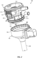
- FIG. 1 is an isometric view of an example trocar assembly 100..
- the trocar assembly 100 includes a trocar 102 and a seal cartridge 104 that may be releasably coupled to the trocar 102.
- the trocar 102 includes a trocar housing 106 and a cannula 108 that extends distally from the trocar housing 106.
- the cannula 108 may comprise an integral extension of the trocar housing 106.
- the trocar housing 106 and the cannula 108 may comprise two separate components that are permanently or semi-permanently mated to one another.
- the trocar 102 may be made of any rigid or semi-rigid material, such as a metal or a plastic.
- the outer lip 202 and the inner lip 204 may be oppositely angled and thereby complement one another to urge the latches 110 to flex radially inward as the outer lip 202 engages the inner lip 204 in the distal direction.
- the latches 110 are able to flex radially outward and opposing flat surfaces of the outer lip 202 and the inner lip 204 engage to help secure and maintain the seal cartridge 104 within the trocar housing 106.
- the latches 110 may be flexed radially inward to disengage the opposing flat surfaces and thereby enable to the outer lip 202 to bypass the inner lip 204 as the seal cartridge 104 is moved proximally.
- the relative spacing of the protrusions 206 may match the relative spacing of the indentations 208 such that when the seal cartridge 104 is received within the trocar housing 106 and the outer lip 202 mates with the inner lip 204, as generally described above, the protrusions 206 may be able to angularly align with and be received within the indentations 208. Receiving the protrusions 206 within the indentations 208 may help restrain the seal cartridge 104 in a particular, discrete angular orientation.
- protrusions 206 and the indentations 208 are elongated features that extend longitudinally and generally parallel to the centerline of the trocar assembly 100
- protrusions 206 and indentations 208 may comprise circular or spherical buttons and the indentations 208 may define corresponding circular or spherical cavities sized to receive the buttons.
- the mating protrusions 206 and indentations 208 may be employed.
- the defined edges of one or both of the protrusions 206 and the indentations 208 may be angled or rounded.
- the seal cartridge 104 may be able to "ratchet" in the angular direction as the protrusions 206 successively engage and disengage the angularly adjacent indentations 208. Having angled or rounded edges may prove advantageous in helping to facilitate easy disengagement and reengagement of the protrusions 206 with the indentations 208 during rotational movement.
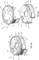
- the top cap 212 may be permanently coupled to the frame 210, such as through the use of an adhesive or via a welding operation that permanently joins the top cap 212 to the frame 210.
- Example welding technologies that may be employed include, but are not limited to, ultrasonic, heated tool, or any combination thereof.
- the top cap 212 may be permanently coupled to the frame 210 via an infrared laser welding operation.
- the frame 210 may be made of a material that is transparent or translucent to the wavelength of the infrared source and thereby allows the electromagnetic radiation of the infrared source to transmit through the frame 210 material with little or no dissipation.
- a pulsed or continuous laser beam may be directed through a portion of the frame 210 that interfaces an opposing portion of the top cap 212, as indicated by the arrow A.
- the laser beam A is shown directed through a radial lip or protrusion 218 defined on the frame 210, and the radial protrusion 218 interfaces with a bottom portion 220 of the top cap 212.
- the laser beam A may be directed through other portions of the frame 210 that interface other opposing portions of the top cap 212.
- the electromagnetic radiation of the laser transmits through the radial protrusion 218 with little or no dissipation, but is absorbed by the opposing material of the top cap 212 after transmitting through the frame 210 material. Absorbing the electromagnetic radiation with the top cap 212 material dramatically increases the temperature at the interface of the top cap 212 and the frame 210 at that location, which heats both components by thermal conduction and results in a welded interface between the two parts once cooled. This process may be repeated multiple times at various locations about the circumference of the seal cartridge 104 to secure the top cap 212 to the frame 210.
- the electromagnetic radiation of the laser B penetrates the frame 210 material with little or no dissipation, but is absorbed by the seal retainer 222 material and causes one or both of the materials to melt and provide a welded interface upon cooling. This process may be repeated multiple times at various locations about the circumference of the seal retainer 222 to secure the seal retainer 222 to the frame 210.
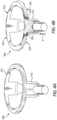
- FIGS. 3A and 3B are enlarged isometric and exploded views, respectively, of the top cap 212, according to one or more embodiments.
- the top cap 212 includes two or more component parts. More particularly, the top cap 212 comprises a main body 302 (alternately referred to as an "upper seal retainer") and a latch ring 304 that is mounted to the main body 302.
- a main body 302 alternatively referred to as an "upper seal retainer”
- latch ring 304 that is mounted to the main body 302.
- the main body 302 may comprise a generally cylindrical structure that defines the central opening 216.
- the main body 302 may comprise a first portion 306a and a second portion 306b attached to or otherwise extending from the first portion 306a.
- the main body 302 may comprise a two-shot molded component where the second portion 306b may be overmolded onto the first portion 306a, or vice versa.
- the first and second portions 306a,b may be made of the same or different materials.
- the main body 302 may comprise a monolithic structure manufactured in a single molding process or fabricated from a single piece of material.
- the main body 302 may also define slots 308 (only one visible) sized and otherwise configured to receive the latches 110 when the latch ring 304 is mounted to the main body 302. As will be appreciated, the number of slots 308 will depend on the number of latches 110. Moreover, in some embodiments, the main body 302 may further define a cutout 310 to accommodate the insufflation valve 112 ( FIG. 1 ).
Landscapes
- Health & Medical Sciences (AREA)
- Surgery (AREA)
- Life Sciences & Earth Sciences (AREA)
- Biomedical Technology (AREA)
- Nuclear Medicine, Radiotherapy & Molecular Imaging (AREA)
- Engineering & Computer Science (AREA)
- Heart & Thoracic Surgery (AREA)
- Medical Informatics (AREA)
- Molecular Biology (AREA)
- Animal Behavior & Ethology (AREA)
- General Health & Medical Sciences (AREA)
- Public Health (AREA)
- Veterinary Medicine (AREA)
- Pathology (AREA)
- Surgical Instruments (AREA)
Applications Claiming Priority (2)
| Application Number | Priority Date | Filing Date | Title |
|---|---|---|---|
| US16/034,942 US10987135B2 (en) | 2018-07-13 | 2018-07-13 | Seal cartridge design for trocar assemblies |
| EP19186144.2A EP3593744B1 (en) | 2018-07-13 | 2019-07-12 | Seal cartridge latch design for trocar assemblies |
Related Parent Applications (2)
| Application Number | Title | Priority Date | Filing Date |
|---|---|---|---|
| EP19186144.2A Division EP3593744B1 (en) | 2018-07-13 | 2019-07-12 | Seal cartridge latch design for trocar assemblies |
| EP19186144.2A Division-Into EP3593744B1 (en) | 2018-07-13 | 2019-07-12 | Seal cartridge latch design for trocar assemblies |
Publications (3)
| Publication Number | Publication Date |
|---|---|
| EP4049600A1 EP4049600A1 (en) | 2022-08-31 |
| EP4049600C0 EP4049600C0 (en) | 2024-07-10 |
| EP4049600B1 true EP4049600B1 (en) | 2024-07-10 |
Family
ID=67262225
Family Applications (2)
| Application Number | Title | Priority Date | Filing Date |
|---|---|---|---|
| EP22169095.1A Active EP4049600B1 (en) | 2018-07-13 | 2019-07-12 | Seal cartridge latch design for trocar assemblies |
| EP19186144.2A Active EP3593744B1 (en) | 2018-07-13 | 2019-07-12 | Seal cartridge latch design for trocar assemblies |
Family Applications After (1)
| Application Number | Title | Priority Date | Filing Date |
|---|---|---|---|
| EP19186144.2A Active EP3593744B1 (en) | 2018-07-13 | 2019-07-12 | Seal cartridge latch design for trocar assemblies |
Country Status (7)
| Country | Link |
|---|---|
| US (2) | US10987135B2 (pl) |
| EP (2) | EP4049600B1 (pl) |
| JP (1) | JP7419335B2 (pl) |
| KR (1) | KR20210032442A (pl) |
| CN (1) | CN112449582B (pl) |
| PL (1) | PL3593744T3 (pl) |
| WO (1) | WO2020012433A1 (pl) |
Families Citing this family (5)
| Publication number | Priority date | Publication date | Assignee | Title |
|---|---|---|---|---|
| USD976404S1 (en) * | 2020-05-01 | 2023-01-24 | Cilag Gmbh International | Trocar depth limiter |
| USD976403S1 (en) * | 2020-05-01 | 2023-01-24 | Cilag Gmbh International | Trocar depth limiter |
| USD963851S1 (en) | 2020-07-10 | 2022-09-13 | Covidien Lp | Port apparatus |
| USD956219S1 (en) | 2020-07-10 | 2022-06-28 | Covidien Lp | Port apparatus |
| US20240000475A1 (en) * | 2022-06-30 | 2024-01-04 | Cilag Gmbh International | Surgical instrument with various alignment features and method for improved disassembly and assembly |
Family Cites Families (11)
| Publication number | Priority date | Publication date | Assignee | Title |
|---|---|---|---|---|
| US5197955A (en) * | 1991-10-18 | 1993-03-30 | Ethicon, Inc. | Universal seal for trocar assembly |
| US5792113A (en) | 1996-12-12 | 1998-08-11 | Ethicon Endo-Surgerym Inc. | Universal seal for a trocar |
| US20040236347A1 (en) | 1999-03-12 | 2004-11-25 | Olympus Optical Co., Ltd. | Trocar sheath tube |
| DE60135765D1 (de) * | 2000-10-13 | 2008-10-23 | Tyco Healthcare | Ventilanordnung mit einer struktur zur durchmesserverkleinerung eines trokars |
| US8012128B2 (en) * | 2003-09-30 | 2011-09-06 | Ethicon Endo-Surgery Inc. | Button latching system for a trocar |
| US8961406B2 (en) | 2009-03-06 | 2015-02-24 | Ethicon Endo-Surgery, Inc. | Surgical access devices and methods providing seal movement in predefined movement regions |
| US8449460B2 (en) * | 2010-03-23 | 2013-05-28 | Ethicon Endo-Surgery, Inc. | Trocar |
| KR101092938B1 (ko) | 2011-04-22 | 2011-12-12 | 배경철 | 복강경 수술용 투관장치 및 그 제조방법 |
| WO2015142794A1 (en) | 2014-03-17 | 2015-09-24 | Intuitive Surgical Operations, Inc. | Cannula seal assembly |
| US9707011B2 (en) * | 2014-11-12 | 2017-07-18 | Covidien Lp | Attachments for use with a surgical access device |
| AU2016315760B2 (en) | 2015-09-01 | 2020-08-13 | Surgiquest, Inc. | Multi-port access device for minimally invasive surgical procedures |
-
2018
- 2018-07-13 US US16/034,942 patent/US10987135B2/en active Active
-
2019
- 2019-07-12 WO PCT/IB2019/055964 patent/WO2020012433A1/en not_active Ceased
- 2019-07-12 CN CN201980045483.8A patent/CN112449582B/zh active Active
- 2019-07-12 EP EP22169095.1A patent/EP4049600B1/en active Active
- 2019-07-12 PL PL19186144.2T patent/PL3593744T3/pl unknown
- 2019-07-12 JP JP2021500892A patent/JP7419335B2/ja active Active
- 2019-07-12 EP EP19186144.2A patent/EP3593744B1/en active Active
- 2019-07-12 KR KR1020217004217A patent/KR20210032442A/ko not_active Withdrawn
-
2021
- 2021-04-26 US US17/240,381 patent/US11992242B2/en active Active
Also Published As
| Publication number | Publication date |
|---|---|
| US20200015853A1 (en) | 2020-01-16 |
| JP2021530289A (ja) | 2021-11-11 |
| US20210244441A1 (en) | 2021-08-12 |
| KR20210032442A (ko) | 2021-03-24 |
| US11992242B2 (en) | 2024-05-28 |
| US10987135B2 (en) | 2021-04-27 |
| EP4049600A1 (en) | 2022-08-31 |
| EP4049600C0 (en) | 2024-07-10 |
| WO2020012433A1 (en) | 2020-01-16 |
| PL3593744T3 (pl) | 2023-05-22 |
| CN112449582A (zh) | 2021-03-05 |
| EP3593744B1 (en) | 2023-01-11 |
| EP3593744A1 (en) | 2020-01-15 |
| JP7419335B2 (ja) | 2024-01-22 |
| CN112449582B (zh) | 2024-03-29 |
Similar Documents
| Publication | Publication Date | Title |
|---|---|---|
| EP4049600B1 (en) | Seal cartridge latch design for trocar assemblies | |
| CN113811252B (zh) | 包括具有固持头部的关节运动销的外科器械 | |
| KR102465136B1 (ko) | 다수의 수술 도구 밀봉 | |
| US20210361289A1 (en) | Adapter, extension, and connector assemblies for surgical devices | |
| JP2023547474A (ja) | 解放可能な閉鎖駆動ロックを備える外科用器具 | |
| US10729443B2 (en) | Adapter, extension, and connector assemblies for surgical devices | |
| JP2023547480A (ja) | 外科用器具の関節運動駆動部が作動可能であるかどうかを検知するように構成されたセンサを備える外科用器具 | |
| JP2023547477A (ja) | 封止可能なインターフェースを備える外科用器具 | |
| US10398439B2 (en) | Adapter, extension, and connector assemblies for surgical devices | |
| JP2023547476A (ja) | 関節運動駆動部が作動可能であることを示すインジケータを備える外科用器具 | |
| JP2023547230A (ja) | ジョー位置合わせシステムを備える外科用器具 | |
| JP2023547231A (ja) | 制限付き移動スイッチを備える外科用器具 | |
| JP2023547234A (ja) | 関節運動インジケータを備える外科用器具 | |
| JP2023547478A (ja) | 関節運動ロックを備えた外科用器具 | |
| JP2023547236A (ja) | 段階的電圧調整始動システムを備える外科用器具 | |
| JP2023547473A (ja) | 格納された閉鎖アクチュエータ停止部を備える外科用器具 | |
| CN113784669A (zh) | 用于外科器械的关节运动致动器 | |
| JP2022532506A (ja) | 外科用器具のための組織停止部 | |
| CN113747845A (zh) | 外科器械上的轴旋转致动器 | |
| KR102853751B1 (ko) | 수술 기기용 시스 그리고 관련 장치 및 방법 | |
| JP2022531239A (ja) | 外科用器具のための関節運動制御マッピング | |
| EP2904885B1 (en) | Housing with releasable locking element | |
| US20160213434A1 (en) | Robot Comprising A Tool | |
| JP2006527045A (ja) | 外科手術用の封鎖具 | |
| EP1994899B1 (en) | Surgical access assembly with winepress seal |
Legal Events
| Date | Code | Title | Description |
|---|---|---|---|
| PUAI | Public reference made under article 153(3) epc to a published international application that has entered the european phase |
Free format text: ORIGINAL CODE: 0009012 |
|
| STAA | Information on the status of an ep patent application or granted ep patent |
Free format text: STATUS: THE APPLICATION HAS BEEN PUBLISHED |
|
| AC | Divisional application: reference to earlier application |
Ref document number: 3593744 Country of ref document: EP Kind code of ref document: P |
|
| AK | Designated contracting states |
Kind code of ref document: A1 Designated state(s): AL AT BE BG CH CY CZ DE DK EE ES FI FR GB GR HR HU IE IS IT LI LT LU LV MC MK MT NL NO PL PT RO RS SE SI SK SM TR |
|
| STAA | Information on the status of an ep patent application or granted ep patent |
Free format text: STATUS: REQUEST FOR EXAMINATION WAS MADE |
|
| 17P | Request for examination filed |
Effective date: 20230228 |
|
| RBV | Designated contracting states (corrected) |
Designated state(s): AL AT BE BG CH CY CZ DE DK EE ES FI FR GB GR HR HU IE IS IT LI LT LU LV MC MK MT NL NO PL PT RO RS SE SI SK SM TR |
|
| GRAP | Despatch of communication of intention to grant a patent |
Free format text: ORIGINAL CODE: EPIDOSNIGR1 |
|
| STAA | Information on the status of an ep patent application or granted ep patent |
Free format text: STATUS: GRANT OF PATENT IS INTENDED |
|
| RIC1 | Information provided on ipc code assigned before grant |
Ipc: A61B 17/00 20060101ALN20240124BHEP Ipc: A61B 17/34 20060101AFI20240124BHEP |
|
| INTG | Intention to grant announced |
Effective date: 20240207 |
|
| GRAS | Grant fee paid |
Free format text: ORIGINAL CODE: EPIDOSNIGR3 |
|
| GRAA | (expected) grant |
Free format text: ORIGINAL CODE: 0009210 |
|
| STAA | Information on the status of an ep patent application or granted ep patent |
Free format text: STATUS: THE PATENT HAS BEEN GRANTED |
|
| AC | Divisional application: reference to earlier application |
Ref document number: 3593744 Country of ref document: EP Kind code of ref document: P |
|
| AK | Designated contracting states |
Kind code of ref document: B1 Designated state(s): AL AT BE BG CH CY CZ DE DK EE ES FI FR GB GR HR HU IE IS IT LI LT LU LV MC MK MT NL NO PL PT RO RS SE SI SK SM TR |
|
| REG | Reference to a national code |
Ref country code: CH Ref legal event code: EP |
|
| REG | Reference to a national code |
Ref country code: DE Ref legal event code: R096 Ref document number: 602019055231 Country of ref document: DE |
|
| U01 | Request for unitary effect filed |
Effective date: 20240809 |
|
| U07 | Unitary effect registered |
Designated state(s): AT BE BG DE DK EE FI FR IT LT LU LV MT NL PT RO SE SI Effective date: 20240902 |
|
| U20 | Renewal fee for the european patent with unitary effect paid |
Year of fee payment: 6 Effective date: 20240902 |
|
| PG25 | Lapsed in a contracting state [announced via postgrant information from national office to epo] |
Ref country code: NO Free format text: LAPSE BECAUSE OF FAILURE TO SUBMIT A TRANSLATION OF THE DESCRIPTION OR TO PAY THE FEE WITHIN THE PRESCRIBED TIME-LIMIT Effective date: 20241010 |
|
| PG25 | Lapsed in a contracting state [announced via postgrant information from national office to epo] |
Ref country code: GR Free format text: LAPSE BECAUSE OF FAILURE TO SUBMIT A TRANSLATION OF THE DESCRIPTION OR TO PAY THE FEE WITHIN THE PRESCRIBED TIME-LIMIT Effective date: 20241011 Ref country code: PL Free format text: LAPSE BECAUSE OF FAILURE TO SUBMIT A TRANSLATION OF THE DESCRIPTION OR TO PAY THE FEE WITHIN THE PRESCRIBED TIME-LIMIT Effective date: 20240710 |
|
| PG25 | Lapsed in a contracting state [announced via postgrant information from national office to epo] |
Ref country code: IS Free format text: LAPSE BECAUSE OF FAILURE TO SUBMIT A TRANSLATION OF THE DESCRIPTION OR TO PAY THE FEE WITHIN THE PRESCRIBED TIME-LIMIT Effective date: 20241110 |
|
| PG25 | Lapsed in a contracting state [announced via postgrant information from national office to epo] |
Ref country code: HR Free format text: LAPSE BECAUSE OF FAILURE TO SUBMIT A TRANSLATION OF THE DESCRIPTION OR TO PAY THE FEE WITHIN THE PRESCRIBED TIME-LIMIT Effective date: 20240710 |
|
| PG25 | Lapsed in a contracting state [announced via postgrant information from national office to epo] |
Ref country code: ES Free format text: LAPSE BECAUSE OF FAILURE TO SUBMIT A TRANSLATION OF THE DESCRIPTION OR TO PAY THE FEE WITHIN THE PRESCRIBED TIME-LIMIT Effective date: 20240710 Ref country code: RS Free format text: LAPSE BECAUSE OF FAILURE TO SUBMIT A TRANSLATION OF THE DESCRIPTION OR TO PAY THE FEE WITHIN THE PRESCRIBED TIME-LIMIT Effective date: 20241010 |
|
| PG25 | Lapsed in a contracting state [announced via postgrant information from national office to epo] |
Ref country code: RS Free format text: LAPSE BECAUSE OF FAILURE TO SUBMIT A TRANSLATION OF THE DESCRIPTION OR TO PAY THE FEE WITHIN THE PRESCRIBED TIME-LIMIT Effective date: 20241010 Ref country code: PL Free format text: LAPSE BECAUSE OF FAILURE TO SUBMIT A TRANSLATION OF THE DESCRIPTION OR TO PAY THE FEE WITHIN THE PRESCRIBED TIME-LIMIT Effective date: 20240710 Ref country code: NO Free format text: LAPSE BECAUSE OF FAILURE TO SUBMIT A TRANSLATION OF THE DESCRIPTION OR TO PAY THE FEE WITHIN THE PRESCRIBED TIME-LIMIT Effective date: 20241010 Ref country code: IS Free format text: LAPSE BECAUSE OF FAILURE TO SUBMIT A TRANSLATION OF THE DESCRIPTION OR TO PAY THE FEE WITHIN THE PRESCRIBED TIME-LIMIT Effective date: 20241110 Ref country code: HR Free format text: LAPSE BECAUSE OF FAILURE TO SUBMIT A TRANSLATION OF THE DESCRIPTION OR TO PAY THE FEE WITHIN THE PRESCRIBED TIME-LIMIT Effective date: 20240710 Ref country code: GR Free format text: LAPSE BECAUSE OF FAILURE TO SUBMIT A TRANSLATION OF THE DESCRIPTION OR TO PAY THE FEE WITHIN THE PRESCRIBED TIME-LIMIT Effective date: 20241011 Ref country code: ES Free format text: LAPSE BECAUSE OF FAILURE TO SUBMIT A TRANSLATION OF THE DESCRIPTION OR TO PAY THE FEE WITHIN THE PRESCRIBED TIME-LIMIT Effective date: 20240710 |
|
| REG | Reference to a national code |
Ref country code: CH Ref legal event code: PL |
|
| PG25 | Lapsed in a contracting state [announced via postgrant information from national office to epo] |
Ref country code: SM Free format text: LAPSE BECAUSE OF FAILURE TO SUBMIT A TRANSLATION OF THE DESCRIPTION OR TO PAY THE FEE WITHIN THE PRESCRIBED TIME-LIMIT Effective date: 20240710 |
|
| PG25 | Lapsed in a contracting state [announced via postgrant information from national office to epo] |
Ref country code: MC Free format text: LAPSE BECAUSE OF FAILURE TO SUBMIT A TRANSLATION OF THE DESCRIPTION OR TO PAY THE FEE WITHIN THE PRESCRIBED TIME-LIMIT Effective date: 20240710 Ref country code: CH Free format text: LAPSE BECAUSE OF NON-PAYMENT OF DUE FEES Effective date: 20240731 |
|
| PG25 | Lapsed in a contracting state [announced via postgrant information from national office to epo] |
Ref country code: CZ Free format text: LAPSE BECAUSE OF FAILURE TO SUBMIT A TRANSLATION OF THE DESCRIPTION OR TO PAY THE FEE WITHIN THE PRESCRIBED TIME-LIMIT Effective date: 20240710 |
|
| PG25 | Lapsed in a contracting state [announced via postgrant information from national office to epo] |
Ref country code: SK Free format text: LAPSE BECAUSE OF FAILURE TO SUBMIT A TRANSLATION OF THE DESCRIPTION OR TO PAY THE FEE WITHIN THE PRESCRIBED TIME-LIMIT Effective date: 20240710 |
|
| PLBE | No opposition filed within time limit |
Free format text: ORIGINAL CODE: 0009261 |
|
| STAA | Information on the status of an ep patent application or granted ep patent |
Free format text: STATUS: NO OPPOSITION FILED WITHIN TIME LIMIT |
|
| 26N | No opposition filed |
Effective date: 20250411 |
|
| PGFP | Annual fee paid to national office [announced via postgrant information from national office to epo] |
Ref country code: GB Payment date: 20250529 Year of fee payment: 7 |
|
| U20 | Renewal fee for the european patent with unitary effect paid |
Year of fee payment: 7 Effective date: 20250606 |
|
| PG25 | Lapsed in a contracting state [announced via postgrant information from national office to epo] |
Ref country code: IE Free format text: LAPSE BECAUSE OF NON-PAYMENT OF DUE FEES Effective date: 20240712 |
|
| PG25 | Lapsed in a contracting state [announced via postgrant information from national office to epo] |
Ref country code: CY Free format text: LAPSE BECAUSE OF FAILURE TO SUBMIT A TRANSLATION OF THE DESCRIPTION OR TO PAY THE FEE WITHIN THE PRESCRIBED TIME-LIMIT; INVALID AB INITIO Effective date: 20190712 |