EP4049598B1 - Medizinische vorrichtung mit einem steuerung der die schnittendebedingungen bestimmt basierend auf der temperatur - Google Patents
Medizinische vorrichtung mit einem steuerung der die schnittendebedingungen bestimmt basierend auf der temperatur Download PDFInfo
- Publication number
- EP4049598B1 EP4049598B1 EP22150065.5A EP22150065A EP4049598B1 EP 4049598 B1 EP4049598 B1 EP 4049598B1 EP 22150065 A EP22150065 A EP 22150065A EP 4049598 B1 EP4049598 B1 EP 4049598B1
- Authority
- EP
- European Patent Office
- Prior art keywords
- temperature
- value
- ultrasonic
- peak
- treatment
- Prior art date
- Legal status (The legal status is an assumption and is not a legal conclusion. Google has not performed a legal analysis and makes no representation as to the accuracy of the status listed.)
- Active
Links
Images







Classifications
-
- A—HUMAN NECESSITIES
- A61—MEDICAL OR VETERINARY SCIENCE; HYGIENE
- A61B—DIAGNOSIS; SURGERY; IDENTIFICATION
- A61B17/00—Surgical instruments, devices or methods
- A61B17/32—Surgical cutting instruments
- A61B17/320068—Surgical cutting instruments using mechanical vibrations, e.g. ultrasonic
-
- A—HUMAN NECESSITIES
- A61—MEDICAL OR VETERINARY SCIENCE; HYGIENE
- A61B—DIAGNOSIS; SURGERY; IDENTIFICATION
- A61B17/00—Surgical instruments, devices or methods
- A61B17/32—Surgical cutting instruments
- A61B17/320068—Surgical cutting instruments using mechanical vibrations, e.g. ultrasonic
- A61B17/320092—Surgical cutting instruments using mechanical vibrations, e.g. ultrasonic with additional movable means for clamping or cutting tissue, e.g. with a pivoting jaw
-
- A—HUMAN NECESSITIES
- A61—MEDICAL OR VETERINARY SCIENCE; HYGIENE
- A61B—DIAGNOSIS; SURGERY; IDENTIFICATION
- A61B17/00—Surgical instruments, devices or methods
- A61B2017/00017—Electrical control of surgical instruments
-
- A—HUMAN NECESSITIES
- A61—MEDICAL OR VETERINARY SCIENCE; HYGIENE
- A61B—DIAGNOSIS; SURGERY; IDENTIFICATION
- A61B17/00—Surgical instruments, devices or methods
- A61B2017/00017—Electrical control of surgical instruments
- A61B2017/00022—Sensing or detecting at the treatment site
- A61B2017/00026—Conductivity or impedance, e.g. of tissue
- A61B2017/0003—Conductivity or impedance, e.g. of tissue of parts of the instruments
-
- A—HUMAN NECESSITIES
- A61—MEDICAL OR VETERINARY SCIENCE; HYGIENE
- A61B—DIAGNOSIS; SURGERY; IDENTIFICATION
- A61B17/00—Surgical instruments, devices or methods
- A61B2017/00017—Electrical control of surgical instruments
- A61B2017/00022—Sensing or detecting at the treatment site
- A61B2017/00084—Temperature
-
- A—HUMAN NECESSITIES
- A61—MEDICAL OR VETERINARY SCIENCE; HYGIENE
- A61B—DIAGNOSIS; SURGERY; IDENTIFICATION
- A61B17/00—Surgical instruments, devices or methods
- A61B17/32—Surgical cutting instruments
- A61B17/320068—Surgical cutting instruments using mechanical vibrations, e.g. ultrasonic
- A61B2017/320082—Surgical cutting instruments using mechanical vibrations, e.g. ultrasonic for incising tissue
-
- A—HUMAN NECESSITIES
- A61—MEDICAL OR VETERINARY SCIENCE; HYGIENE
- A61B—DIAGNOSIS; SURGERY; IDENTIFICATION
- A61B17/00—Surgical instruments, devices or methods
- A61B17/32—Surgical cutting instruments
- A61B17/320068—Surgical cutting instruments using mechanical vibrations, e.g. ultrasonic
- A61B17/320092—Surgical cutting instruments using mechanical vibrations, e.g. ultrasonic with additional movable means for clamping or cutting tissue, e.g. with a pivoting jaw
- A61B2017/320094—Surgical cutting instruments using mechanical vibrations, e.g. ultrasonic with additional movable means for clamping or cutting tissue, e.g. with a pivoting jaw additional movable means performing clamping operation
-
- A—HUMAN NECESSITIES
- A61—MEDICAL OR VETERINARY SCIENCE; HYGIENE
- A61B—DIAGNOSIS; SURGERY; IDENTIFICATION
- A61B90/00—Instruments, implements or accessories specially adapted for surgery or diagnosis and not covered by any of the groups A61B1/00 - A61B50/00, e.g. for luxation treatment or for protecting wound edges
- A61B90/06—Measuring instruments not otherwise provided for
- A61B2090/064—Measuring instruments not otherwise provided for for measuring force, pressure or mechanical tension
Definitions
- the systems, devices and exemplary methods disclosed herein are directed to medical devices, and in particular to medical devices for ultrasonic treatment.
- the ultrasonic impedance (“US impedance”) is monitored, and detection of a change of the US impedance is equated to completion of cutting of the living tissue. When such a change is detected, the ultrasonic vibration is stopped.
- U.S. Patent No. 8,749,116 discloses an ultrasonic treatment apparatus which includes a treatment section to which an ultrasonic vibration is transmitted and a jaw openable and closable relative to the treatment section.
- this ultrasonic treatment apparatus when vibration generating electric power is transmitted from an electric power source to a vibration generating section, the ultrasonic vibration is generated in an ultrasonic transducer and the generated ultrasonic vibration is transmitted to the treatment section, which then treats a treated target such as a biological tissue by use of the transmitted ultrasonic vibration.
- opening and closing directions of the jaw are perpendicular (transverse) to a transmitting direction of the ultrasonic vibration.
- the ultrasonic vibration When the ultrasonic vibration is transmitted to the treatment section in a state where the treated target is grasped between the treatment section and the jaw, frictional heat is generated between the treated target and the treatment section. By the frictional heat, the treated target is coagulated and simultaneously incised. Furthermore, in the ultrasonic treatment apparatus, an ultrasonic impedance value of the vibration generating electric power is detected with time, and it is judged whether the ultrasonic impedance value is within a range of a first default threshold or more and a second default threshold or less, with the second default threshold being greater than the first default threshold.
- U.S. Patent No. 9,848,903 discloses calculating and detecting the ultrasonic impedance value, as well as calculating the peak of the ultrasonic impedance values at which time a cut of living tissue should be complete.
- detection of the peak of the impedance does not always yield an accurate determination of when a cut of living tissue is complete.
- US 2017/0252087 A1 refers to an energy treatment instrument that includes a housing body. One end of a cable is connected to the housing body. The other end of the cable is attached to an energy control device. A footswitch is electrically connected to the energy control device. The energy control device controls a supply of energy to the energy treatment instrument.
- a cylindrical shaft is coupled to the housing body.
- An end effector is coupled to a distal portion of the shaft.
- the end effector includes a first clamp and a second clamp.
- the first clamp includes a support member rotatably coupled to the shaft. An outer surface of the first clamp is provided with a grasping surface.
- a relay member is attached to a grasping surface side with respect to the support member, and a blade is attached to a grasping surface side with respect to the relay member.
- a heating body is provided between the blade and relay member.
- the energy control device includes a controller. When energy is supplied to the energy treatment instrument and a grasped treated target is treated, the controller detects whether an operation input is performed in the footswitch. If the operation input is detected, the controller starts outputting high-frequency electric energy and heat generating electric energy. If the output of high-frequency electric energy is started, the controller controls the output of high-frequency electric energy by constant electric power control by which high-frequency electric power is kept constant with time at a first electric power.
- the controller adjusts the magnitudes of heat generating current, heat generating voltage and heat generating electric power, and adjusts a calorific value in the heating body, in such a state that the temperature of the grasping surface is kept constant with time at a reference temperature.
- the controller detects, with the passing of time, a resistance value of the heating body and the temperature of the grasping surface, and executes feedback control.
- the controller detects a tissue impedance with the passing of time. If the tissue impedance is an impedance threshold value or more, the controller controls the output of high-frequency electric energy by the constant electric power control which keeps the high-frequency electric power constant with time at a second electric power greater than the first electric power.
- control of a medical device for ultrasonic treatment is based on the temperature behavior of the vibration transmission member, such as the rate of change in temperature at the site of a vibration transmission member of an end-effector.
- control of a medical device for ultrasonic treatment is based on both the change of ultrasonic impedance during treatment and the temperature behavior of the vibration transmission member, such as the rate of change in temperature at the site of the vibration transmission member. Detecting both the change of ultrasonic impedance and the rate of change in temperature allows for discriminating false peaks (that are not associated with completion of cutting of living tissue being treated) from true peaks (that are associated with completion of cutting of living tissue being treated).
- completion of the ultrasonic treatment can by based on integrated temperature of the vibration transmission member.
- strain values are monitored so as to detect changes in the clinician's operation of the medical device for ultrasonic treatment, such as parameters related to the back-and-forth longitudinal movement of the transmission rod, and are then correlated to the ultrasonic impedance to discriminate false peaks (that can be caused by such clinician's operation) from true peaks (that are indicative of end of treatment conditions).
- the present disclosure further discloses a medical device, per se, which operates based on the method for detecting the completion of the ultrasonic treatment while also incorporating methods to detect the true peak due to completion of the cut of the living tissue medical devices for ultrasonic treatment.
- the present invention provides a medical control device, as defined in claim 1, and an ultrasonic treatment system, as defined in claim 5.
- Preferred embodiments are defined by the dependent claims.
- the medical device includes an ultrasonic instrument having a vibration transmission member that vibrates ultrasonically, a power source configured to supply electric energy to the ultrasonic instrument, and a processor including a control unit operably connected to the power source, the method including: controlling supply of the electric energy to the ultrasonic instrument, obtaining a temperature value related to a temperature of the vibration transmission member, the vibration transmission member being separate from a transducer, and controlling the power source to reduce or stop the supply of electric energy of the power source based on the rate of change of the temperature value.
- Another useful method not forming part of the present disclosure is a method of operating a medical device for ultrasonic treatment, the medical device including an ultrasonic instrument having a vibration transmission member that vibrates ultrasonically, a power source configured to provide power to an ultrasonic oscillator circuit for providing ultrasonic vibration the vibration transmission member to cut living tissue, and a processor including a control unit operably connected to the power source, the method including: calculating a plurality of temperature rate change values corresponding to a temperature increase rate per unit time, based on the temperature of the vibration transmission member, identifying a peak value among the plurality of temperature rate change values, the peak value being a largest value among the plurality of temperature rate change values, determining whether the peak value is a false peak corresponding to an incomplete cut of living tissue or a true peak corresponding to a complete cut of living tissue, when it is determined that the peak value is a false peak, then controlling the power source to reduce or stop providing power to the ultrasonic oscillator circuit, and when it is determined that the peak value is a true
- An object of the present disclosure is to provide a medical control device, including, a power source configured to: connect to an ultrasonic instrument having a vibration transmission member that vibrates ultrasonically, and supply electric energy to the ultrasonic instrument, a processor including a control unit operably connected to the power source, the control unit being configured to: control the supply of the electric energy to the ultrasonic instrument, obtain a temperature value related to a temperature of the vibration transmission member, and control the power source to reduce or stop the supply of electric energy of the power source based on the rate of change of the temperature value.
- Another medical control device includes: a power source configured to provide power to an ultrasonic oscillator circuit for providing ultrasonic vibration to cut living tissue, a processor operably connected to the power source, the processor being configured to: calculate a plurality of temperature rate change values corresponding to a temperature increase rate per unit time, based on the temperature of the vibration transmission member, identify a peak value among the plurality of temperature rate change values, the peak value being a largest value among the plurality of temperature rate change values, determine whether the peak value is a false peak corresponding to an incomplete cut of living tissue or a true peak corresponding to a complete cut of living tissue, when it is determined that the peak value is a false peak, then control the power source to reduce or stop providing power to the ultrasonic oscillator circuit, and when it is determined that the peak value is a true peak, then control the power source to continue providing power to the ultrasonic oscillator circuit.
- Medical devices that can provide ultrasonic vibration to apply heat to a body tissue are used in various surgical procedures, for example, to cauterize the blood vessel, or to weld or seal tissues or lumens.
- One of the common types of devices includes an end-effector that can produce ultrasound vibration at the site of the end-effector.
- the end-effector includes a vibration transmission member and a pad that are moved to come into contact with each other.
- a processor monitors ultrasonic impedance. The processor detects completion of cut of the living tissue based on the change of the ultrasonic impedance, and stops (or reduces) the ultrasonic vibration.
- the living tissue After the ultrasonic treatment is started, the living tissue is denatured by frictional heat and hardened, and the ultrasonic impedance increases.
- the living tissue is cut, and the vibration transmission member and pad come into contact with each other.
- the ultrasonic impedance decreases as the pad is denatured due to frictional heat generated by ultrasonic vibration.
- By detecting a point (peak) at which the ultrasonic impedance changes from an increase to a decrease it is possible to detect the completion of cut of the living tissue.
- the wear of the pad can be suppressed by speeding up the detection of completion of cut of the living tissue. It is thus possible to suppress excessive invasion of the living tissue.
- a “false peak” may occur before the peak, i.e., the "true peak,” due to completion of the cut of the living tissue.
- the processor detects the false peak, the processor reduces or stops the ultrasonic vibration despite there being no completion of the cut of the living tissue.
- the living tissue is a layered structure formed of two or more layers, e.g., a cervix, it is possible that the false peak may appear when the first layer is cut.
- Embodiments detect the completion of cut of the living tissue by detecting the peak in the change of ultrasonic impedance and by monitoring the change of the rate of increase of the temperature of the vibration transmission member. Some embodiments detect the completion of cut of the living tissue by monitoring the change of the rate of increase of the temperature of the vibration transmission member without detecting the impedance.
- one aspect of the present disclosure describes a method for accurately detecting the true peak due to completion of the cut of the living tissue.
- the present disclosure further describes control of the medical device based on the rate of change in temperature at the site of the vibration transmission member of the end-effector or based on both the change of ultrasonic impedance during treatment and the rate of change in temperature, such as the rate of change in temperature at the site of the end-effector. Detecting both the change of ultrasonic impedance and the rate of change in temperature allows for discriminating false peaks (that are not associated with completion of cutting of living tissue being treated) from true peaks (that are associated with completion of cutting of living tissue being treated).
- the present disclosure further relates to a medical device for ultrasonic treatment, per se, which operates based on the method for detecting the true peak due to completion of the cut of the living tissue.
- patient comprises any and all organisms and includes the term “subject.”
- a patient can be a human or an animal.
- the temperature of the vibration transmission member specifically indicates the temperature of the tip.
- the temperature of the vibration transmission member is treated in the same manner.
- the temperature is, for example, calculated based on the current and voltage supplied to the vibration transmission member, or acquired by various known methods.
- FIG. 1 shows a schematic of a medical device, in accordance with an embodiment of the present disclosure.
- the medical device 1 for treating a tissue of a patient is provided with a treatment instrument 2, a controller 3 having a processor includes an input controller 4, such as an actuation switch.
- the treatment instrument 2 may be, for example, a surgical operation energy inosculation apparatus used for welding biological tissue, such as in an abdominal cavity through an abdominal wall, or incising, such as in an open surgery procedure or laparoscopy.
- the treatment instrument 2 has a grip 2A1, a shaft 2A2, and a treatment section constituted by an end-effector 10 such as, for example, an openable or pivoting pair of grasping sections (including a first grasping section 11A and a second grasping section 11B) for grasping biological tissue to perform treatment.
- the grasping sections as whole are also referred to herein as the "treatment portion" or the "treatment section” of the medical instrument.
- the symbol A or B may be omitted.
- each of the first grasping section 11A and the second grasping section 11B may be referred to as the grasping section.
- the grip 2A1 is connected to the controller 3 via a cable 2L.
- the grip 2A1 has an opening/closing actuator 2A3, such as a trigger, for a surgeon to operate opening and closing of the treatment section and is in such a shape that the surgeon can easily clasp, for example, in a substantially L shape.
- the opening/closing actuator 2A3 is arranged at one end of the grip 2A1 and is integrated with the treatment section to transmit operation of the opening/closing actuator 2A3 to the treatment section.
- a grasping portion 2A4 is provided for a clinician to grasp when operating the instrument 2.
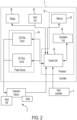
- FIG. 2 shows a schematic of a controller in accordance with an embodiment of the present disclosure.
- the controller 3 may include a processor 32, a display 36, an input unit 42, and a power source 44.
- the processor 32 may include a memory 34, a calculation unit 46 and a control unit 40.
- the calculation unit 46 and the control unit 40 are formed of an integrated circuit including a CPU (Central Processing Unit), an ASIC (Application Specific Integrated Circuit) or an FPGA (Field Programmable Gate Array).
- the calculation unit 46 and the control unit 40 may be formed as a single integrated circuit, or may be formed of a plurality of integrated circuits.
- various parameters used for estimating a current temperature such as, for example, the specific heat capacity of the treatment portion, the thermal resistance of the treatment portion, the thermal conductivity of the treatment portion, or a contact area between the body tissue and the treatment portion, any of which may be stored in memory 34, e.g., in a look-up table stored in the memory 34.
- the look-up table may include the values of the corresponding parameters for different treatment portions.
- the look-up table may include the parameters for muscle tissue, adipose tissue, blood vessels, intestinal wall, or other tissue types.
- estimating the current temperature may include determining the type of tissue on which the procedure is being performed, and determining the corresponding parameter values in the look-up table for estimating the current temperature.
- the procedure name may be used as the basis for entry into the look-up table.
- the calculation unit 46 is configured to compute the estimated current temperature as well as other parameters that are needed for computing the estimated current temperature and rate of change of temperature, which may require estimating a current temperature.
- estimating the current temperature may include determining the type of biological tissue on which the procedure is being performed, and determining the corresponding parameter values in the look-up table for estimating the current temperature.
- the procedure name may be used as the basis for entry into the look-up table.
- the control unit 40 is configured to control the power source 44 and the display 36 based on the commands provided by the processor 32 using the parameters computed by the calculation unit 46.
- a temperature may be determined, sensed, or calculated, by suitable devices and methods, for example, as disclosed in U.S. Provisional Patent Application Serial No. 63/042,594, filed on June 23, 2020 , titled "A METHOD FOR CONTROLLING A MEDICAL DEVICE AND A MEDICAL DEVICE IMPLEMENTING THE SAME".
- the data related to the various parameters is a value of the contact area calculated using size and shape of the end-effector, in particular, the treatment portion of the end-effector, and how the end-effector is used (e.g., related to the procedure) and this data is stored in the memory in advance.
- the various parameters can also correspondingly change during the medical procedure, and having the data for the various parameters readily available in memory allows for dynamic updating during the medical procedure.
- the display section 36 which displays treatment conditions and the like, and a setting operation section 35 for the surgeon to set the treatment conditions and the like on a front panel.
- a input controller 4 may be connected to the controller 3 via a cable 4L.
- the clinician may turn the power output from the controller 3 to the treatment instrument 2 ON or OFF by an input controller 4, such as by pressing a pedal of a foot switch of the input controller 4.
- the foot switch is not an essential component and any input controller can be utilized, such as a switch or the like which the clinician operates by hand or other alternative input controller.
- the controller 3 includes a processor 32, which controls the application of power to the instrument 2 via the power source 44 so as to maintain a temperature at the end-effector 10 in a safe and effective range.
- the processor 32 may override the input provided by the clinician (e.g., through the input controller 4) for turning the power to the instrument 2 ON or OFF.
- control unit 40 may be configured to cause the instrument 2 to increase or decrease a grasping force with which the instrument 2 or the end-effector 10 thereof grasps the portion of tissue on which the procedure is being performed.
- FIG. 3 is a graph showing a rate of increase of temperature (in %) over time (in seconds) in a medical device.
- FIG. 3 shows that the completion of the cut of the living tissue can be detected by the rate of change of the increase of the temperature ( ⁇ T, in %) of the vibration transmission member during treatment.
- An incomplete cut 303 (dashed circle) has the first rate of change of temperature ( ⁇ T1), which is less than the threshold ( ⁇ T th ).
- the peak of the rate of change of the increase of temperature at the incomplete cut 303 is a false peak where there is a temporary drop in the rate of change of the increase of temperature before it increases again.
- a complete cut 304 (solid circle) has the second rate of change of temperature ( ⁇ T2), which is greater than the threshold ( ⁇ T th ).
- the peak of the rate of change of the increase of temperature at the complete cut 304 is a true peak.
- the rate of change of the increase of the temperature will then drop after the cut is complete (arrow 305).
- FIG. 4 is a flow chart for a process of detecting completion of a cut of living tissue.
- operation S401 the ultrasonic treatment is started.
- operation S402 a determination is made whether a peak has been detected in the rate of change of the increase of the temperature of the vibration transmission member during treatment. If “NO”, then treatment continues with operation S402. If “YES”, then a determination is made whether the change of temperature increase rate is greater than the threshold value ( ⁇ Ttn) over a certain period of time (S403). If “NO”, then treatment continues with operation S402. If “YES”, then it is determined that the cut of the living tissue has been completed, and treatment stops (or is reduced) (S404).
- FIG. 5 is a graph showing ultrasonic impedance (in kiloohms (k ⁇ )) over time (in seconds) in a medical device.
- ultrasonic impedance of the ultrasonic transmission member may be concurrently monitored.
- FIG. 5 shows that, while the ultrasonic impedance is being monitored, the impedance will generally increase (arrow 501) until the cut is completed, then will decrease (arrow 502) until power is stopped or reduced.
- a false impedance peak 503 may be detected (dashed circle) where there is a temporary drop in impedance, followed by another increase in impedance until the true impedance peak 504 (solid circle).
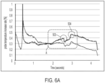
- FIG. 6A is a graph showing a rate of increase of temperature (in %) over time (in seconds) from FIG. 3 overlaid based on time with the ultrasonic impedance (in kiloohms (k ⁇ )) over time (in seconds) from FIG. 5 in a medical device.
- FIG. 6B is a detail of a portion A of the graph of FIG. 6A .
- the temperature increase rate per unit time is calculated based on the temperature of the vibration transmission member.
- the rate of change in the temperature ( ⁇ T) at the corresponding time period is analyzed.
- the rate of change in the temperature ( ⁇ T) is calculated, as discussed above, and is compared to a threshold value ( ⁇ T th ).
- a threshold value ⁇ T th
- the increase ( ⁇ T) from the minimum of the temperature increase rate of the vibration transmission member is smaller than a threshold value ( ⁇ T th )
- that peak of ultrasonic impedance is determined to be a false peak.
- the increase ( ⁇ T) from the minimum of the temperature increase rate of the vibration transmission member is larger than the threshold value( ⁇ T th )
- that peak of ultrasonic impedance is determined to be a true peak.
- the difference in the first rate of change of temperature ( ⁇ T1) at the false impedance peak 503, taken at the time associated with the temperature at 505, is less than a threshold value ( ⁇ T th ), while the difference in the second rate of change of temperature ( ⁇ T2) at the true peak 504, taken at the time associated with the temperature at 506, is greater than the threshold value ( ⁇ T th ).
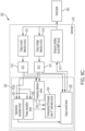
- FIG. 6C is a block diagram of a functional operation of the medical device of FIG. 6A .
- a generator 610 may be controlled by a field-programmable gate array (FPGA) 620, programmable circuit, or other integrated circuit, and may control a hand piece 630, e.g., the treatment instrument 2 of FIG. 1 .
- FPGA field-programmable gate array
- the generator 610 includes an ultrasonic oscillator circuit 613, e.g., an amplifier circuit, an output current detection circuit 611, an output voltage detection circuit 612, and analog-to-digital converters (ADCs) 614, 615.
- the ultrasonic oscillator circuit 613 outputs an ultrasonic oscillation signal to the hand piece 630.
- the output current detection circuit 611 detects the current of the ultrasonic oscillation signal from the ultrasonic oscillator circuit 613.
- the output voltage detection circuit 612 detects the voltage of the ultrasonic oscillation signal from the ultrasonic oscillator circuit 613.
- the output current detection circuit 611 and the output voltage detection circuit 612 output analog signals, corresponding to their respective detected values, to respective analog-to-digital converters 614, 615.
- the FPGA 620 may include an impedance calculation block 621 for calculating impedance, a power calculation block 622 for calculating how much power has been supplied, a frequency detection block 623 for detecting a vibration frequency of the medical device, a temperature(t)/increase rate of T estimation block 624 for calculating the increase ( ⁇ T) from the minimum of the temperature increase rate of the vibration transmission member, and an output control block 625 for controlling output of the ultrasonic oscillator circuit 613 of the generator 610.
- Each of the ADCs 614, 615 of the generator 610 outputs to the impedance calculation block 621, the power calculation block 622, the frequency detection block 623, and the output control block 625.
- the power calculation block 622 and the frequency detection block 623 output to the temperature(t)/increase rate of T estimation block 624.
- a minimum value and a peak value of the temperature increase rate is detected at the temperature(t)/increase rate of T estimation block 624.
- the output control block 625 receives results from the temperature(t)/increase rate of T estimation block 624 and the impedance calculation block 621, and uses those results along with the values from the ADCs 614, 615 to control the ultrasonic oscillator circuit 613.
- the output control block 625 controls the ultrasonic oscillator circuit 613 to continue to operate. If the temperature(t)/increase rate of T estimation block 624 determines that the increase ( ⁇ T) from the minimum of the temperature increase rate of the vibration transmission member is larger than the threshold value, it is determined to be a true peak, and the output control block 625 controls the ultrasonic oscillator circuit 613 to reduce or stop operation and cease transmission of oscillation to the hand piece 630.
- FIG. 7 is a flow chart for a process of detecting completion of a cut of living tissue.
- operation S701 the ultrasonic treatment is started.
- operation S702 a determination is made whether a peak has been detected in the ultrasonic impedance of the vibration transmission member during treatment based on the power supplied to the vibration transmission member. If “NO”, then treatment continues with operation S702. If “YES”, then, in operation S703, a determination is made whether a peak has been detected in the rate of change of the increase of the temperature of the vibration transmission member during treatment. If “NO”, then treatment continues with operation S702. If “YES”, then a determination is made whether the change of temperature increase rate is greater than the threshold value T th over a certain period of time (S704).
- operation S702 may be performed after or concurrently with operations S703 and S704.
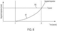
- FIG. 8 is a graph showing integrated temperature over time in a medical device.
- some embodiments may be configured to detect whether the living tissue is cut only by the integrated temperature of the vibration transmission member.
- the integrated temperature may also be used in addition to the above-discussed rate of change of the temperature increase and/or impedance.
- the integrated temperature can be determined by calculating the amount of energy, e.g., in joules (J), at the tip of the medical device, e.g., at the distal tip of the vibration transmission member of the end-effector 10 of FIG. 1 .
- the calculation may be performed by integrating the temperature of the vibration transmission member.
- the memory 34 may include information about protein denaturation temperatures of various tissues to determine whether the tissue has been cut.
- line 801 starts integrating the temperature of the vibration transmission member while ultrasonic energy is being supplied.
- output is stopped (or reduced) and treatment ends.
- FIG. 9 is a flow chart for a process of detecting completion of a cut of living tissue.
- operation S901 the ultrasonic treatment is started.
- operation S902 a determination is made whether a peak has been detected in the ultrasonic impedance of the vibration transmission member during treatment. If “NO”, then treatment continues with operation S902. If “YES”, then, in operation S903, a determination is made whether a peak has been detected in the rate of change of the increase of the temperature of the vibration transmission member during treatment. If “NO”, then treatment continues with operation S902. If “YES”, then a determination is made whether the change of temperature increase rate is greater than the threshold value T th over a certain period of time (S904). If “NO”, then treatment continues with operation S902. If “YES”, then it is determined that the cut of the living tissue has been completed, and treatment stops (or is reduced) (S905). It should be appreciated that operation S902 may be performed after or concurrently with operations S903 and S904.
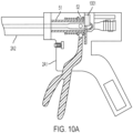
- FIG. 10A is a cross-section of a medical device, in accordance with an embodiment of the present disclosure.
- FIG. 10B is a graph showing operation of the medical device of FIG. 10A .
- the shaft 2A2 of the medical device 1 of FIG. 1 may extend internally to the grip 2A1.
- the internal portion of the shaft 2A2 may include an internal shaft 51 and a slider 52 that contributes to the longitudinal movement of the internal shaft 51.
- a force sensor 1001 e.g., a strain sensor, may be installed at the end of the slider 52 for detecting the gripping force of the clinician operating the medical device.
- a change in the gripping force means that the back-and-forth movement of the shaft is being generated.
- the force sensor 1001 (e.g., strain sensor) is used to detect a strain, which is a stress in the long axis direction generated by the longitudinal movement of the shaft, after the output is started.
- a higher strain detected by the force sensor 1001 means that the clinician is squeezing the opening/closing actuator 2A3 harder.
- the change in the rate of increase of temperature as in the FIG. 7 example, if the change in the amount of the strain, i.e., a distortion value, exceeds a certain range or exceeds a certain rate of change, it is determined to be a false peak. For example, the clinician may want to continue cutting, and so is gripping harder.
- a strain which is a stress in the long axis direction generated by the longitudinal movement of the shaft, after the output is started.
- a higher strain detected by the force sensor 1001 means that the clinician is squeezing the opening/closing actuator 2A3 harder.
- the change in the amount of the strain i.e., a
- part (I) shows the change in the rate of increase of temperature, similarly to the FIG. 7 example, with the false peak 1003 and true peak 1004.
- Part (II) shows the strain value detected by the force sensor 1001 of FIG. 10A . If the amount of strain at the corresponding time, e.g., as indicated by line 1005, exceeds a threshold, then the peak 1003 is occurring at the same time as the distortion value in strain is occurring, such that a false peak is determined.
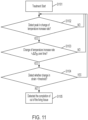
- FIG. 11 is a flow chart for a process of detecting completion of a cut of living tissue.
- the ultrasonic treatment is started.
- a determination is made whether a peak has been detected in the rate of change of the increase of the temperature of the vibration transmission member during treatment. If “NO”, then treatment continues with operation S1102. If “YES”, then a determination is made whether the change of temperature increase rate is greater than the threshold value T th over a certain period of time (S1103). If “NO”, then treatment continues with operation S1102. If “YES”, then, in operation S1104, a determination is made whether a change in the strain value detected by the force sensor 1001 of FIG. 10A is greater than a threshold.
- any of the clauses herein, which depend from the independent clause may depend from any one of the dependent clauses.
- any of the dependent clauses may be combined with any other one or more dependent clauses.
- a claim may include some or all of the words (e.g., steps, operations, means or components) recited in a sentence, a phrase or a paragraph.
- a claim may include some or all of the words recited in one or more sentences, phrases or paragraphs.
- some of the words in each of the sentences, phrases, paragraphs or dependent clauses may be removed.
- additional words or elements may be added to a clause, a sentence, a phrase or a paragraph.
- the subject technology may be implemented without utilizing some of the components, elements, functions or operations described herein. In one aspect, the subject technology may be implemented utilizing additional components, elements, functions or operations.
- a plunger component includes reference to one or more plunger components
- the magnet includes reference to one or more magnets.
- the terms “about,” “substantially,” and “approximately” may provide an industry-accepted tolerance for their corresponding terms and/or relativity between items, such as from less than one percent to five percent.
- the term “substantially” refers to the complete or nearly complete extent or degree of an action, characteristic, property, state, structure, item, or result.
- the techniques described herein may be implemented in hardware, software, firmware, or any combination thereof, unless specifically described as being implemented in a specific manner. Any features described as modules or components may also be implemented together in an integrated logic device or separately as discrete but interoperable logic devices. If implemented in software, the techniques may be realized at least in part by a non-transitory processor-readable storage medium comprising instructions that, when executed, performs one or more of the methods described above.
- the non-transitory processor-readable storage medium may comprise random access memory (RAM) such as synchronous dynamic random access memory (SDRAM), read only memory (ROM), non-volatile random access memory (NVRAM), electrically erasable programmable read-only memory (EEPROM), FLASH memory, other known storage media, and the like.
- RAM synchronous dynamic random access memory
- ROM read only memory
- NVRAM non-volatile random access memory
- EEPROM electrically erasable programmable read-only memory
- FLASH memory other known storage media, and the like.
- the techniques additionally, or alternatively, may be realized at least in part by a processor-readable communication medium that carries or communicates code in the form of instructions or data structures and that can be accessed, read, and/or executed by a computer or other processor.
- a carrier wave may be employed to carry computer-readable electronic data such as those used in transmitting and receiving electronic mail or in accessing a network such as the Internet or a local area network (LAN).
- LAN local area
Landscapes
- Health & Medical Sciences (AREA)
- Surgery (AREA)
- Engineering & Computer Science (AREA)
- Life Sciences & Earth Sciences (AREA)
- Heart & Thoracic Surgery (AREA)
- Nuclear Medicine, Radiotherapy & Molecular Imaging (AREA)
- Mechanical Engineering (AREA)
- Biomedical Technology (AREA)
- Dentistry (AREA)
- Medical Informatics (AREA)
- Molecular Biology (AREA)
- Animal Behavior & Ethology (AREA)
- General Health & Medical Sciences (AREA)
- Public Health (AREA)
- Veterinary Medicine (AREA)
- Surgical Instruments (AREA)
Claims (6)
- Medizinische Steuerungsvorrichtung, die umfasst;eine Energiequelle (44), die konfiguriert ist, um:mit einem Ultraschallgerät (2) verbunden zu werden, das ein Schwingungsübertragungselement besitzt, das mit Ultraschall schwingt, unddem Ultraschallgerät (2) elektrische Energie zuzuführen;einen Prozessor (32), der eine Steuereinheit (40) umfasst, die betriebsfähig mit der Energiequelle (44) verbunden ist, wobei die Steuereinheit (40) so konfiguriert ist, dass sie:die Versorgung des Ultraschallgeräts (2) mit elektrischer Energie zu steuert,einen Temperaturwert erhält, der sich auf eine Temperatur des Schwingungsübertragungselements bezieht, unddie Energiequelle (44) steuert, um die Zufuhr von elektrischer Energie der Energiequelle (44) auf der Grundlage der Änderungsrate des Temperaturwerts zu verringern oder zu stoppen;einen Generator (610), der umfasst:eine Ultraschalloszillatorschaltung (613), die so konfiguriert ist, dass sie ein Ultraschallschwingungssignal an ein Handstück (630) liefert,eine Ausgangsstromerfassungsschaltung (611), die so konfiguriert ist, dass sie einen Strom des von der Ultraschalloszillatorschaltung (613) ausgegebenen Ultraschallschwingungssignals erfasst,eine Ausgangsspannungserfassungsschaltung (612), die so konfiguriert ist, dass sie eine Spannung des von der Ultraschalloszillatorschaltung (613) ausgegebenen Ultraschallschwingungssignals erfasst,einen ersten Analog-Digital-Wandler, ADC, (614), der so konfiguriert ist, dass er einen analogen Stromwert von der Ausgangsstromerfassungsschaltung (611) in einen digitalen Stromwert umwandelt,einen zweiten ADC (615), der so konfiguriert ist, dass er einen analogen Spannungswert von der
Ausgangsspannungserfassungsschaltung (612) in einen digitalen Spannungswert umwandelt; undeine integrierte Schaltung, die so konfiguriert ist, dass sie die Ultraschalloszillatorschaltung (613) des Generators (610) steuert, wobei die integrierte Schaltung umfasst:einen Impedanzberechnungsblock (621), der so konfiguriert ist, dass er einen Impedanzwert auf der Grundlage berechnet von:dem digitalen Stromwert vom ersten ADC (614), unddem digitalen Spannungswert aus dem zweiten ADC (615),einen Leistungsberechnungsblock (622), der so konfiguriert ist, dass er eine Leistungsmenge berechnet, die von der Ultraschalloszillatorschaltung (613) geliefert wurde, basierend auf:dem digitalen Stromwert vom ersten ADC (614), unddem digitalen Spannungswert aus dem zweiten ADC (615),einen Frequenzerfassungsblock (623), der so konfiguriert ist, dass er eine Vibrationsfrequenz der medizinischen Vorrichtung erfasst, basierend auf:dem digitalen Stromwert vom ersten ADC (614), unddem digitalen Spannungswert aus dem zweiten ADC (615),einen Temperatur (T)/Erhöhungsrate der Temperatur (T)-Schätzblock (624), der so konfiguriert ist, dass er die Erhöhung (ΔT) aus einem Minimum der Temperaturerhöhungsrate des Schwingungsübertragungselements berechnet, basierend auf:der berechneten Leistung aus dem Leistungsberechnungsblock (622), undder erkannten Frequenz aus demFrequenzerkennungsblock (623), undeinen Ausgangssteuerblock (625), der so konfiguriert ist, dass er das Ultraschallschwingungssignal der Ultraschalloszillatorschaltung (613) des Generators (610) steuert auf der Grundlage:dem digitalen Stromwert aus dem ersten ADC (614),dem digitalen Spannungswert aus dem zweiten ADC (615),den berechneten Impedanzwert aus dem Impedanzberechnungsblock (621), unddem geschätzten Anstieg (ΔT) aus dem Minimum der Temperaturanstiegsrate des Schwingungsübertragungselements aus dem Temperatur (T)/Anstiegsrate der Temperatur (T)-Schätzblock (624). - Medizinische Steuerungsvorrichtung nach Anspruch 1, wobei:der Temperatur(T)/Erhöhungsrate der Temperatur (T)-Schätzblock (624) ferner konfiguriert ist, um einen Minimalwert und einen Spitzenwert der Temperaturerhöhungsrate zu erfassen, undder Anstieg (ΔT) vom Minimum der Temperaturanstiegsrate des Schwingungsübertragungselements eine Differenz zwischen dem Spitzenwert und dem Minimalwert ist.
- Medizinische Steuerungsvorrichtung nach Anspruch 2, wobei der Temperatur(T)/Erhöhungsrate der Temperatur (T)-Schätzblock (624) ferner so konfiguriert ist, dass er:bestimmt, ob der Spitzenwert ein falscher Spitzenwert ist, der einem unvollständigen Schnitt von lebendem Gewebe entspricht, oder ein echter Spitzenwert ist, der einem vollständigen Schnitt von lebendem Gewebe entspricht,wenn festgestellt wird, dass der Spitzenwert ein falscher Spitzenwert ist, der Ausgangssteuerblock (625) ferner so konfiguriert ist, dass er die Ultraschalloszillatorschaltung (613) steuert, um das Ultraschallschwingungssignal zu stoppen oder zu reduzieren, undwenn festgestellt wird, dass der Spitzenwert ein echter Spitzenwert ist, dann ist der Ausgangssteuerblock (625) weiterhin so konfiguriert, dass er die Ultraschalloszillatorschaltung (613) steuert, um das Ultraschallschwingungssignal aufrechtzuerhalten.
- Medizinische Steuerungsvorrichtung nach Anspruch 3, wobei, wenn der Anstieg (ΔT) kleiner als ein Schwellenwert für die Temperaturänderungsrate ist, der Temperatur(T)/Erhöhungsrate der Temperatur (T)-Schätzblock (624) ferner so konfiguriert ist, dass er den Spitzenwert als falschen Spitzenwert bestimmt.
- Ultraschallbehandlungssystem, das die medizinische Steuerungsvorrichtung nach Anspruch 3 umfasst, ferner umfassend:ein Steuergerät (3) mit einer Eingangssteuerung (4), die umfasst:den Prozessor, undeinen Betätigungsschalter; undein Behandlungsinstrument (2), das umfasst:einen Behandlungsabschnitt, der einen Endeffektor (10) umfasst, der so konfiguriert ist, dass er lebendes Gewebe zur Durchführung der Behandlung erfasst,einen Griff (2A1), der über ein Kabel (2L) mit dem Steuergerät (3) verbunden ist, wobei der Griff (2A1) umfasst:einen Öffnungs-/Schließaktuator (2A3), der so konfiguriert ist, dass er das Öffnen und Schließen des Behandlungsabschnitts betätigt, wobei der Öffnungs-/Schließaktuator (2A3) an einem Ende des Griffs (2A1) angeordnet ist und so konfiguriert ist, dass er die Betätigung des Öffnungs-/Schließaktuators (2A3) auf den Behandlungsabschnitt überträgt, undeinen Greifabschnitt (2A4), der so konfiguriert ist, dass er ergriffen wird, wenn das Behandlungsinstrument (2) betätigt wird, und eine Welle (2A2).
- Ultraschallbehandlungssystem nach Anspruch 5, wobei:sich die Welle (2A2) in den Griff (2A1) erstreckt und umfasst:einen inneren Teil im Inneren des Griffs (2A1), undeinen äußeren Teil außerhalb des Griffs (2A1),der innere Teil der Welle (2A2) umfasst:eine innere Welle (51) undeinen Schieber (52), der so gestaltet ist, dass er zur Längsbewegung der inneren Welle (51) beiträgt, undein Kraftsensor (1001) an einem Ende des Schiebers (52) angeordnet ist, wobei der Kraftsensor (1001) so konfiguriert ist, dass er einen Dehnungswert erfasst, wobei der Dehnungswert eine Spannung in einer Längsachsenrichtung ist, die durch eine Längsbewegung der Welle (2A2) erzeugt wird, während die Energiequelle (44) den Strom oder die Versorgung mit elektrischer Energie für die Ultraschallschwingung bereitstellt, wobei optional:der von dem Kraftsensor (1001) erfasste Dehnungswert proportional zu einer Greifkraft des Benutzers ist, so dass ein höherer Dehnungswert einem stärkeren Zusammendrücken des Öffnungs-/Schließaktuators (2A3) durch den Benutzer entspricht, undder Prozessor (32) ferner so konfiguriert ist, dass er die Stromversorgung oder die Zufuhr elektrischer Energie für Ultraschallschwingungen durch die Energiequelle (44) reduziert oder stoppt, wenn die Änderung des Wertes des Dehnungssensors (1001) einen Dehnungsschwellenwert überschreitet.
Applications Claiming Priority (2)
| Application Number | Priority Date | Filing Date | Title |
|---|---|---|---|
| US202163153548P | 2021-02-25 | 2021-02-25 | |
| US17/544,295 US12274466B2 (en) | 2021-02-25 | 2021-12-07 | Medical device and method for controlling the same including discriminating end-of-cut conditions based on temperature |
Publications (2)
| Publication Number | Publication Date |
|---|---|
| EP4049598A1 EP4049598A1 (de) | 2022-08-31 |
| EP4049598B1 true EP4049598B1 (de) | 2023-06-21 |
Family
ID=79230775
Family Applications (1)
| Application Number | Title | Priority Date | Filing Date |
|---|---|---|---|
| EP22150065.5A Active EP4049598B1 (de) | 2021-02-25 | 2022-01-03 | Medizinische vorrichtung mit einem steuerung der die schnittendebedingungen bestimmt basierend auf der temperatur |
Country Status (3)
| Country | Link |
|---|---|
| US (1) | US12274466B2 (de) |
| EP (1) | EP4049598B1 (de) |
| CN (1) | CN114948100B (de) |
Families Citing this family (2)
| Publication number | Priority date | Publication date | Assignee | Title |
|---|---|---|---|---|
| CN116058929A (zh) * | 2023-02-13 | 2023-05-05 | 河南省驼人医疗科技有限公司 | 一种基于滑动窗口的超声刀切割组织结束反馈控制方法 |
| CN119367008B (zh) * | 2024-10-31 | 2025-10-03 | 重庆西山科技股份有限公司 | 降低热损伤的温度控制方法、存储介质、能量输出设备及手术操作系统 |
Family Cites Families (13)
| Publication number | Priority date | Publication date | Assignee | Title |
|---|---|---|---|---|
| US9044261B2 (en) * | 2007-07-31 | 2015-06-02 | Ethicon Endo-Surgery, Inc. | Temperature controlled ultrasonic surgical instruments |
| US8095327B2 (en) * | 2008-04-15 | 2012-01-10 | Olympus Medical Systems Corp. | Power supply apparatus for operation |
| US9089360B2 (en) | 2008-08-06 | 2015-07-28 | Ethicon Endo-Surgery, Inc. | Devices and techniques for cutting and coagulating tissue |
| US8461744B2 (en) * | 2009-07-15 | 2013-06-11 | Ethicon Endo-Surgery, Inc. | Rotating transducer mount for ultrasonic surgical instruments |
| US9241731B2 (en) * | 2012-04-09 | 2016-01-26 | Ethicon Endo-Surgery, Inc. | Rotatable electrical connection for ultrasonic surgical instruments |
| US9788851B2 (en) * | 2012-04-18 | 2017-10-17 | Ethicon Llc | Surgical instrument with tissue density sensing |
| EP3108836B1 (de) | 2014-02-17 | 2019-01-09 | Olympus Corporation | Ultraschallbehandlungsgerät |
| WO2017018205A1 (ja) | 2015-07-24 | 2017-02-02 | オリンパス株式会社 | エネルギー処置システム、エネルギー制御装置及びエネルギー処置具 |
| WO2018016016A1 (ja) * | 2016-07-20 | 2018-01-25 | オリンパス株式会社 | エネルギー制御装置及び処置システム |
| WO2018020578A1 (ja) * | 2016-07-26 | 2018-02-01 | オリンパス株式会社 | エネルギー制御装置及び処置システム |
| US11229475B2 (en) * | 2017-05-22 | 2022-01-25 | Cilag Gmbh International | Combination ultrasonic and electrosurgical instrument and method for sealing tissue with various termination parameters |
| US11707293B2 (en) * | 2018-03-08 | 2023-07-25 | Cilag Gmbh International | Ultrasonic sealing algorithm with temperature control |
| US20210393310A1 (en) | 2020-06-23 | 2021-12-23 | Olympus Corporation | Method for controlling a medical device and a medical device implementing the same |
-
2021
- 2021-12-07 US US17/544,295 patent/US12274466B2/en active Active
-
2022
- 2022-01-03 EP EP22150065.5A patent/EP4049598B1/de active Active
- 2022-02-24 CN CN202210173727.4A patent/CN114948100B/zh active Active
Also Published As
| Publication number | Publication date |
|---|---|
| US12274466B2 (en) | 2025-04-15 |
| CN114948100B (zh) | 2026-03-17 |
| EP4049598A1 (de) | 2022-08-31 |
| US20220265303A1 (en) | 2022-08-25 |
| CN114948100A (zh) | 2022-08-30 |
Similar Documents
| Publication | Publication Date | Title |
|---|---|---|
| US12251124B2 (en) | Surgical instrument with staged application of electrosurgical and ultrasonic energy | |
| EP2691037B1 (de) | Chirurgische ultraschallinstrumente | |
| EP2853222B1 (de) | Systeme zur Bestimmung von Parametern mittels chirurgischer Vorrichtungen | |
| JP6133535B2 (ja) | 触覚フィードバックを有する電気外科用密封器具 | |
| US20250292086A1 (en) | Systems and methods for estimating tissue parameters using surgical devices | |
| EP4049598A1 (de) | Medizinische vorrichtung und verfahren zur steuerung derselben, einschliesslich der unterscheidung von schnittendebedingungen basierend auf der temperatur | |
| CN111031944A (zh) | 具有可调节的能量模式的组合超声和电外科器械以及用于限制刀温度的方法 | |
| EP3011924A1 (de) | Behandlungssystem, instrumentensteuerungsvorrichtung und behandlungsbetriebsverfahren | |
| CN104244850B (zh) | 具有组织密度感测的外科器械 | |
| US20130121366A1 (en) | Methods of measuring conditions of an ultrasonic instrument | |
| CN103648423A (zh) | 具有机械反馈和电反馈的马达驱动型电外科装置 | |
| US10045815B2 (en) | Energy treatment device and energy control device | |
| US20210393310A1 (en) | Method for controlling a medical device and a medical device implementing the same | |
| CN108697453B (zh) | 能量手术器械 | |
| CN118383839B (zh) | 一种超声刀的刀尖温度预估方法及预估系统 | |
| JP5816780B1 (ja) | 処置具及び処置システム | |
| CN114945334A (zh) | 用于控制超声手术系统的系统和方法 | |
| US12279788B2 (en) | End-point detection method and medical device controller and treatment system with end-point detection, particularly for electrosurgery | |
| EP3329874A1 (de) | Energiebehandlungswerkzeug, behandlungssystem und steuerungsvorrichtung | |
| JP2005160733A (ja) | 手術用処置具 |
Legal Events
| Date | Code | Title | Description |
|---|---|---|---|
| PUAI | Public reference made under article 153(3) epc to a published international application that has entered the european phase |
Free format text: ORIGINAL CODE: 0009012 |
|
| STAA | Information on the status of an ep patent application or granted ep patent |
Free format text: STATUS: REQUEST FOR EXAMINATION WAS MADE |
|
| 17P | Request for examination filed |
Effective date: 20220103 |
|
| AK | Designated contracting states |
Kind code of ref document: A1 Designated state(s): AL AT BE BG CH CY CZ DE DK EE ES FI FR GB GR HR HU IE IS IT LI LT LU LV MC MK MT NL NO PL PT RO RS SE SI SK SM TR |
|
| GRAP | Despatch of communication of intention to grant a patent |
Free format text: ORIGINAL CODE: EPIDOSNIGR1 |
|
| STAA | Information on the status of an ep patent application or granted ep patent |
Free format text: STATUS: GRANT OF PATENT IS INTENDED |
|
| RIC1 | Information provided on ipc code assigned before grant |
Ipc: A61B 90/00 20160101ALN20230126BHEP Ipc: A61B 17/00 20060101ALN20230126BHEP Ipc: A61B 17/32 20060101AFI20230126BHEP |
|
| INTG | Intention to grant announced |
Effective date: 20230209 |
|
| GRAS | Grant fee paid |
Free format text: ORIGINAL CODE: EPIDOSNIGR3 |
|
| GRAA | (expected) grant |
Free format text: ORIGINAL CODE: 0009210 |
|
| STAA | Information on the status of an ep patent application or granted ep patent |
Free format text: STATUS: THE PATENT HAS BEEN GRANTED |
|
| AK | Designated contracting states |
Kind code of ref document: B1 Designated state(s): AL AT BE BG CH CY CZ DE DK EE ES FI FR GB GR HR HU IE IS IT LI LT LU LV MC MK MT NL NO PL PT RO RS SE SI SK SM TR |
|
| REG | Reference to a national code |
Ref country code: CH Ref legal event code: EP |
|
| P01 | Opt-out of the competence of the unified patent court (upc) registered |
Effective date: 20230528 |
|
| REG | Reference to a national code |
Ref country code: DE Ref legal event code: R096 Ref document number: 602022000133 Country of ref document: DE |
|
| REG | Reference to a national code |
Ref country code: AT Ref legal event code: REF Ref document number: 1580331 Country of ref document: AT Kind code of ref document: T Effective date: 20230715 |
|
| REG | Reference to a national code |
Ref country code: IE Ref legal event code: FG4D |
|
| REG | Reference to a national code |
Ref country code: LT Ref legal event code: MG9D |
|
| REG | Reference to a national code |
Ref country code: NL Ref legal event code: MP Effective date: 20230621 |
|
| PG25 | Lapsed in a contracting state [announced via postgrant information from national office to epo] |
Ref country code: SE Free format text: LAPSE BECAUSE OF FAILURE TO SUBMIT A TRANSLATION OF THE DESCRIPTION OR TO PAY THE FEE WITHIN THE PRESCRIBED TIME-LIMIT Effective date: 20230621 Ref country code: NO Free format text: LAPSE BECAUSE OF FAILURE TO SUBMIT A TRANSLATION OF THE DESCRIPTION OR TO PAY THE FEE WITHIN THE PRESCRIBED TIME-LIMIT Effective date: 20230921 |
|
| REG | Reference to a national code |
Ref country code: AT Ref legal event code: MK05 Ref document number: 1580331 Country of ref document: AT Kind code of ref document: T Effective date: 20230621 |
|
| PG25 | Lapsed in a contracting state [announced via postgrant information from national office to epo] |
Ref country code: RS Free format text: LAPSE BECAUSE OF FAILURE TO SUBMIT A TRANSLATION OF THE DESCRIPTION OR TO PAY THE FEE WITHIN THE PRESCRIBED TIME-LIMIT Effective date: 20230621 Ref country code: NL Free format text: LAPSE BECAUSE OF FAILURE TO SUBMIT A TRANSLATION OF THE DESCRIPTION OR TO PAY THE FEE WITHIN THE PRESCRIBED TIME-LIMIT Effective date: 20230621 Ref country code: LV Free format text: LAPSE BECAUSE OF FAILURE TO SUBMIT A TRANSLATION OF THE DESCRIPTION OR TO PAY THE FEE WITHIN THE PRESCRIBED TIME-LIMIT Effective date: 20230621 Ref country code: LT Free format text: LAPSE BECAUSE OF FAILURE TO SUBMIT A TRANSLATION OF THE DESCRIPTION OR TO PAY THE FEE WITHIN THE PRESCRIBED TIME-LIMIT Effective date: 20230621 Ref country code: HR Free format text: LAPSE BECAUSE OF FAILURE TO SUBMIT A TRANSLATION OF THE DESCRIPTION OR TO PAY THE FEE WITHIN THE PRESCRIBED TIME-LIMIT Effective date: 20230621 Ref country code: GR Free format text: LAPSE BECAUSE OF FAILURE TO SUBMIT A TRANSLATION OF THE DESCRIPTION OR TO PAY THE FEE WITHIN THE PRESCRIBED TIME-LIMIT Effective date: 20230922 |
|
| PG25 | Lapsed in a contracting state [announced via postgrant information from national office to epo] |
Ref country code: FI Free format text: LAPSE BECAUSE OF FAILURE TO SUBMIT A TRANSLATION OF THE DESCRIPTION OR TO PAY THE FEE WITHIN THE PRESCRIBED TIME-LIMIT Effective date: 20230621 |
|
| PG25 | Lapsed in a contracting state [announced via postgrant information from national office to epo] |
Ref country code: SK Free format text: LAPSE BECAUSE OF FAILURE TO SUBMIT A TRANSLATION OF THE DESCRIPTION OR TO PAY THE FEE WITHIN THE PRESCRIBED TIME-LIMIT Effective date: 20230621 |
|
| PG25 | Lapsed in a contracting state [announced via postgrant information from national office to epo] |
Ref country code: ES Free format text: LAPSE BECAUSE OF FAILURE TO SUBMIT A TRANSLATION OF THE DESCRIPTION OR TO PAY THE FEE WITHIN THE PRESCRIBED TIME-LIMIT Effective date: 20230621 |
|
| PG25 | Lapsed in a contracting state [announced via postgrant information from national office to epo] |
Ref country code: IS Free format text: LAPSE BECAUSE OF FAILURE TO SUBMIT A TRANSLATION OF THE DESCRIPTION OR TO PAY THE FEE WITHIN THE PRESCRIBED TIME-LIMIT Effective date: 20231021 |
|
| PG25 | Lapsed in a contracting state [announced via postgrant information from national office to epo] |
Ref country code: SM Free format text: LAPSE BECAUSE OF FAILURE TO SUBMIT A TRANSLATION OF THE DESCRIPTION OR TO PAY THE FEE WITHIN THE PRESCRIBED TIME-LIMIT Effective date: 20230621 Ref country code: SK Free format text: LAPSE BECAUSE OF FAILURE TO SUBMIT A TRANSLATION OF THE DESCRIPTION OR TO PAY THE FEE WITHIN THE PRESCRIBED TIME-LIMIT Effective date: 20230621 Ref country code: RO Free format text: LAPSE BECAUSE OF FAILURE TO SUBMIT A TRANSLATION OF THE DESCRIPTION OR TO PAY THE FEE WITHIN THE PRESCRIBED TIME-LIMIT Effective date: 20230621 Ref country code: PT Free format text: LAPSE BECAUSE OF FAILURE TO SUBMIT A TRANSLATION OF THE DESCRIPTION OR TO PAY THE FEE WITHIN THE PRESCRIBED TIME-LIMIT Effective date: 20231023 Ref country code: IS Free format text: LAPSE BECAUSE OF FAILURE TO SUBMIT A TRANSLATION OF THE DESCRIPTION OR TO PAY THE FEE WITHIN THE PRESCRIBED TIME-LIMIT Effective date: 20231021 Ref country code: ES Free format text: LAPSE BECAUSE OF FAILURE TO SUBMIT A TRANSLATION OF THE DESCRIPTION OR TO PAY THE FEE WITHIN THE PRESCRIBED TIME-LIMIT Effective date: 20230621 Ref country code: EE Free format text: LAPSE BECAUSE OF FAILURE TO SUBMIT A TRANSLATION OF THE DESCRIPTION OR TO PAY THE FEE WITHIN THE PRESCRIBED TIME-LIMIT Effective date: 20230621 Ref country code: CZ Free format text: LAPSE BECAUSE OF FAILURE TO SUBMIT A TRANSLATION OF THE DESCRIPTION OR TO PAY THE FEE WITHIN THE PRESCRIBED TIME-LIMIT Effective date: 20230621 Ref country code: AT Free format text: LAPSE BECAUSE OF FAILURE TO SUBMIT A TRANSLATION OF THE DESCRIPTION OR TO PAY THE FEE WITHIN THE PRESCRIBED TIME-LIMIT Effective date: 20230621 |
|
| PG25 | Lapsed in a contracting state [announced via postgrant information from national office to epo] |
Ref country code: PL Free format text: LAPSE BECAUSE OF FAILURE TO SUBMIT A TRANSLATION OF THE DESCRIPTION OR TO PAY THE FEE WITHIN THE PRESCRIBED TIME-LIMIT Effective date: 20230621 |
|
| REG | Reference to a national code |
Ref country code: DE Ref legal event code: R097 Ref document number: 602022000133 Country of ref document: DE |
|
| PLBE | No opposition filed within time limit |
Free format text: ORIGINAL CODE: 0009261 |
|
| STAA | Information on the status of an ep patent application or granted ep patent |
Free format text: STATUS: NO OPPOSITION FILED WITHIN TIME LIMIT |
|
| PG25 | Lapsed in a contracting state [announced via postgrant information from national office to epo] |
Ref country code: DK Free format text: LAPSE BECAUSE OF FAILURE TO SUBMIT A TRANSLATION OF THE DESCRIPTION OR TO PAY THE FEE WITHIN THE PRESCRIBED TIME-LIMIT Effective date: 20230621 |
|
| PG25 | Lapsed in a contracting state [announced via postgrant information from national office to epo] |
Ref country code: SI Free format text: LAPSE BECAUSE OF FAILURE TO SUBMIT A TRANSLATION OF THE DESCRIPTION OR TO PAY THE FEE WITHIN THE PRESCRIBED TIME-LIMIT Effective date: 20230621 |
|
| 26N | No opposition filed |
Effective date: 20240322 |
|
| PG25 | Lapsed in a contracting state [announced via postgrant information from national office to epo] |
Ref country code: SI Free format text: LAPSE BECAUSE OF FAILURE TO SUBMIT A TRANSLATION OF THE DESCRIPTION OR TO PAY THE FEE WITHIN THE PRESCRIBED TIME-LIMIT Effective date: 20230621 Ref country code: IT Free format text: LAPSE BECAUSE OF FAILURE TO SUBMIT A TRANSLATION OF THE DESCRIPTION OR TO PAY THE FEE WITHIN THE PRESCRIBED TIME-LIMIT Effective date: 20230621 |
|
| PG25 | Lapsed in a contracting state [announced via postgrant information from national office to epo] |
Ref country code: MC Free format text: LAPSE BECAUSE OF FAILURE TO SUBMIT A TRANSLATION OF THE DESCRIPTION OR TO PAY THE FEE WITHIN THE PRESCRIBED TIME-LIMIT Effective date: 20230621 |
|
| PG25 | Lapsed in a contracting state [announced via postgrant information from national office to epo] |
Ref country code: MC Free format text: LAPSE BECAUSE OF FAILURE TO SUBMIT A TRANSLATION OF THE DESCRIPTION OR TO PAY THE FEE WITHIN THE PRESCRIBED TIME-LIMIT Effective date: 20230621 |
|
| PG25 | Lapsed in a contracting state [announced via postgrant information from national office to epo] |
Ref country code: LU Free format text: LAPSE BECAUSE OF NON-PAYMENT OF DUE FEES Effective date: 20240103 |
|
| PG25 | Lapsed in a contracting state [announced via postgrant information from national office to epo] |
Ref country code: LU Free format text: LAPSE BECAUSE OF NON-PAYMENT OF DUE FEES Effective date: 20240103 |
|
| PG25 | Lapsed in a contracting state [announced via postgrant information from national office to epo] |
Ref country code: BE Free format text: LAPSE BECAUSE OF NON-PAYMENT OF DUE FEES Effective date: 20240131 |
|
| PG25 | Lapsed in a contracting state [announced via postgrant information from national office to epo] |
Ref country code: FR Free format text: LAPSE BECAUSE OF NON-PAYMENT OF DUE FEES Effective date: 20240131 |
|
| PG25 | Lapsed in a contracting state [announced via postgrant information from national office to epo] |
Ref country code: FR Free format text: LAPSE BECAUSE OF NON-PAYMENT OF DUE FEES Effective date: 20240131 Ref country code: BE Free format text: LAPSE BECAUSE OF NON-PAYMENT OF DUE FEES Effective date: 20240131 |
|
| REG | Reference to a national code |
Ref country code: BE Ref legal event code: MM Effective date: 20240131 |
|
| PG25 | Lapsed in a contracting state [announced via postgrant information from national office to epo] |
Ref country code: BG Free format text: LAPSE BECAUSE OF FAILURE TO SUBMIT A TRANSLATION OF THE DESCRIPTION OR TO PAY THE FEE WITHIN THE PRESCRIBED TIME-LIMIT Effective date: 20230621 |
|
| PG25 | Lapsed in a contracting state [announced via postgrant information from national office to epo] |
Ref country code: BG Free format text: LAPSE BECAUSE OF FAILURE TO SUBMIT A TRANSLATION OF THE DESCRIPTION OR TO PAY THE FEE WITHIN THE PRESCRIBED TIME-LIMIT Effective date: 20230621 |
|
| PG25 | Lapsed in a contracting state [announced via postgrant information from national office to epo] |
Ref country code: IE Free format text: LAPSE BECAUSE OF NON-PAYMENT OF DUE FEES Effective date: 20240103 |
|
| PG25 | Lapsed in a contracting state [announced via postgrant information from national office to epo] |
Ref country code: IE Free format text: LAPSE BECAUSE OF NON-PAYMENT OF DUE FEES Effective date: 20240103 |
|
| PG25 | Lapsed in a contracting state [announced via postgrant information from national office to epo] |
Ref country code: CY Free format text: LAPSE BECAUSE OF FAILURE TO SUBMIT A TRANSLATION OF THE DESCRIPTION OR TO PAY THE FEE WITHIN THE PRESCRIBED TIME-LIMIT; INVALID AB INITIO Effective date: 20220103 |
|
| REG | Reference to a national code |
Ref country code: CH Ref legal event code: PL |
|
| PG25 | Lapsed in a contracting state [announced via postgrant information from national office to epo] |
Ref country code: CH Free format text: LAPSE BECAUSE OF NON-PAYMENT OF DUE FEES Effective date: 20250131 |
|
| PG25 | Lapsed in a contracting state [announced via postgrant information from national office to epo] |
Ref country code: TR Free format text: LAPSE BECAUSE OF FAILURE TO SUBMIT A TRANSLATION OF THE DESCRIPTION OR TO PAY THE FEE WITHIN THE PRESCRIBED TIME-LIMIT Effective date: 20230621 |
|
| PGFP | Annual fee paid to national office [announced via postgrant information from national office to epo] |
Ref country code: DE Payment date: 20260121 Year of fee payment: 5 |
|
| PG25 | Lapsed in a contracting state [announced via postgrant information from national office to epo] |
Ref country code: CH Free format text: THE PATENT HAS BEEN ANNULLED BY A DECISION OF A NATIONAL AUTHORITY Effective date: 20250131 |
|
| PG25 | Lapsed in a contracting state [announced via postgrant information from national office to epo] |
Ref country code: HU Free format text: LAPSE BECAUSE OF FAILURE TO SUBMIT A TRANSLATION OF THE DESCRIPTION OR TO PAY THE FEE WITHIN THE PRESCRIBED TIME-LIMIT; INVALID AB INITIO Effective date: 20220103 |