EP4048986B1 - Verfahren zur bestimmung der normalkraft eines reifens - Google Patents
Verfahren zur bestimmung der normalkraft eines reifens Download PDFInfo
- Publication number
- EP4048986B1 EP4048986B1 EP19794952.2A EP19794952A EP4048986B1 EP 4048986 B1 EP4048986 B1 EP 4048986B1 EP 19794952 A EP19794952 A EP 19794952A EP 4048986 B1 EP4048986 B1 EP 4048986B1
- Authority
- EP
- European Patent Office
- Prior art keywords
- tyre
- normal force
- vehicle
- max
- suspension
- Prior art date
- Legal status (The legal status is an assumption and is not a legal conclusion. Google has not performed a legal analysis and makes no representation as to the accuracy of the status listed.)
- Active
Links
- 238000000034 method Methods 0.000 title claims description 62
- 239000000725 suspension Substances 0.000 claims description 90
- 230000001133 acceleration Effects 0.000 claims description 22
- 230000006835 compression Effects 0.000 claims description 22
- 238000007906 compression Methods 0.000 claims description 22
- 230000014509 gene expression Effects 0.000 claims description 19
- 238000012545 processing Methods 0.000 claims description 10
- 238000004590 computer program Methods 0.000 claims description 8
- 238000005259 measurement Methods 0.000 claims description 8
- 230000005484 gravity Effects 0.000 claims description 3
- 230000008901 benefit Effects 0.000 description 13
- 230000006870 function Effects 0.000 description 6
- 238000004422 calculation algorithm Methods 0.000 description 4
- 238000005457 optimization Methods 0.000 description 4
- 239000013598 vector Substances 0.000 description 3
- 238000004364 calculation method Methods 0.000 description 2
- 238000004891 communication Methods 0.000 description 2
- 230000000295 complement effect Effects 0.000 description 2
- 230000009471 action Effects 0.000 description 1
- 238000007792 addition Methods 0.000 description 1
- 238000013459 approach Methods 0.000 description 1
- 238000010276 construction Methods 0.000 description 1
- 238000013016 damping Methods 0.000 description 1
- 238000010586 diagram Methods 0.000 description 1
- 230000004069 differentiation Effects 0.000 description 1
- 238000012986 modification Methods 0.000 description 1
- 230000004048 modification Effects 0.000 description 1
- 230000003287 optical effect Effects 0.000 description 1
- 230000002085 persistent effect Effects 0.000 description 1
- 230000000135 prohibitive effect Effects 0.000 description 1
- 230000004044 response Effects 0.000 description 1
- 238000005096 rolling process Methods 0.000 description 1
- 239000007787 solid Substances 0.000 description 1
- 238000006467 substitution reaction Methods 0.000 description 1
Images


Classifications
-
- G—PHYSICS
- G01—MEASURING; TESTING
- G01G—WEIGHING
- G01G23/00—Auxiliary devices for weighing apparatus
- G01G23/002—Means for correcting for obliquity of mounting
-
- B—PERFORMING OPERATIONS; TRANSPORTING
- B60—VEHICLES IN GENERAL
- B60G—VEHICLE SUSPENSION ARRANGEMENTS
- B60G17/00—Resilient suspensions having means for adjusting the spring or vibration-damper characteristics, for regulating the distance between a supporting surface and a sprung part of vehicle or for locking suspension during use to meet varying vehicular or surface conditions, e.g. due to speed or load
- B60G17/015—Resilient suspensions having means for adjusting the spring or vibration-damper characteristics, for regulating the distance between a supporting surface and a sprung part of vehicle or for locking suspension during use to meet varying vehicular or surface conditions, e.g. due to speed or load the regulating means comprising electric or electronic elements
- B60G17/018—Resilient suspensions having means for adjusting the spring or vibration-damper characteristics, for regulating the distance between a supporting surface and a sprung part of vehicle or for locking suspension during use to meet varying vehicular or surface conditions, e.g. due to speed or load the regulating means comprising electric or electronic elements characterised by the use of a specific signal treatment or control method
- B60G17/0182—Resilient suspensions having means for adjusting the spring or vibration-damper characteristics, for regulating the distance between a supporting surface and a sprung part of vehicle or for locking suspension during use to meet varying vehicular or surface conditions, e.g. due to speed or load the regulating means comprising electric or electronic elements characterised by the use of a specific signal treatment or control method involving parameter estimation, e.g. observer, Kalman filter
-
- G—PHYSICS
- G01—MEASURING; TESTING
- G01G—WEIGHING
- G01G19/00—Weighing apparatus or methods adapted for special purposes not provided for in the preceding groups
- G01G19/02—Weighing apparatus or methods adapted for special purposes not provided for in the preceding groups for weighing wheeled or rolling bodies, e.g. vehicles
- G01G19/025—Weighing apparatus or methods adapted for special purposes not provided for in the preceding groups for weighing wheeled or rolling bodies, e.g. vehicles wheel-load scales
-
- B—PERFORMING OPERATIONS; TRANSPORTING
- B60—VEHICLES IN GENERAL
- B60T—VEHICLE BRAKE CONTROL SYSTEMS OR PARTS THEREOF; BRAKE CONTROL SYSTEMS OR PARTS THEREOF, IN GENERAL; ARRANGEMENT OF BRAKING ELEMENTS ON VEHICLES IN GENERAL; PORTABLE DEVICES FOR PREVENTING UNWANTED MOVEMENT OF VEHICLES; VEHICLE MODIFICATIONS TO FACILITATE COOLING OF BRAKES
- B60T8/00—Arrangements for adjusting wheel-braking force to meet varying vehicular or ground-surface conditions, e.g. limiting or varying distribution of braking force
- B60T8/17—Using electrical or electronic regulation means to control braking
- B60T8/172—Determining control parameters used in the regulation, e.g. by calculations involving measured or detected parameters
-
- B—PERFORMING OPERATIONS; TRANSPORTING
- B60—VEHICLES IN GENERAL
- B60T—VEHICLE BRAKE CONTROL SYSTEMS OR PARTS THEREOF; BRAKE CONTROL SYSTEMS OR PARTS THEREOF, IN GENERAL; ARRANGEMENT OF BRAKING ELEMENTS ON VEHICLES IN GENERAL; PORTABLE DEVICES FOR PREVENTING UNWANTED MOVEMENT OF VEHICLES; VEHICLE MODIFICATIONS TO FACILITATE COOLING OF BRAKES
- B60T8/00—Arrangements for adjusting wheel-braking force to meet varying vehicular or ground-surface conditions, e.g. limiting or varying distribution of braking force
- B60T8/17—Using electrical or electronic regulation means to control braking
- B60T8/1755—Brake regulation specially adapted to control the stability of the vehicle, e.g. taking into account yaw rate or transverse acceleration in a curve
- B60T8/17551—Brake regulation specially adapted to control the stability of the vehicle, e.g. taking into account yaw rate or transverse acceleration in a curve determining control parameters related to vehicle stability used in the regulation, e.g. by calculations involving measured or detected parameters
-
- B—PERFORMING OPERATIONS; TRANSPORTING
- B60—VEHICLES IN GENERAL
- B60W—CONJOINT CONTROL OF VEHICLE SUB-UNITS OF DIFFERENT TYPE OR DIFFERENT FUNCTION; CONTROL SYSTEMS SPECIALLY ADAPTED FOR HYBRID VEHICLES; ROAD VEHICLE DRIVE CONTROL SYSTEMS FOR PURPOSES NOT RELATED TO THE CONTROL OF A PARTICULAR SUB-UNIT
- B60W40/00—Estimation or calculation of non-directly measurable driving parameters for road vehicle drive control systems not related to the control of a particular sub unit, e.g. by using mathematical models
- B60W40/12—Estimation or calculation of non-directly measurable driving parameters for road vehicle drive control systems not related to the control of a particular sub unit, e.g. by using mathematical models related to parameters of the vehicle itself, e.g. tyre models
- B60W40/13—Load or weight
-
- G—PHYSICS
- G01—MEASURING; TESTING
- G01G—WEIGHING
- G01G19/00—Weighing apparatus or methods adapted for special purposes not provided for in the preceding groups
- G01G19/08—Weighing apparatus or methods adapted for special purposes not provided for in the preceding groups for incorporation in vehicles
-
- G—PHYSICS
- G01—MEASURING; TESTING
- G01G—WEIGHING
- G01G19/00—Weighing apparatus or methods adapted for special purposes not provided for in the preceding groups
- G01G19/14—Weighing apparatus or methods adapted for special purposes not provided for in the preceding groups for weighing suspended loads
-
- B—PERFORMING OPERATIONS; TRANSPORTING
- B60—VEHICLES IN GENERAL
- B60G—VEHICLE SUSPENSION ARRANGEMENTS
- B60G17/00—Resilient suspensions having means for adjusting the spring or vibration-damper characteristics, for regulating the distance between a supporting surface and a sprung part of vehicle or for locking suspension during use to meet varying vehicular or surface conditions, e.g. due to speed or load
- B60G17/015—Resilient suspensions having means for adjusting the spring or vibration-damper characteristics, for regulating the distance between a supporting surface and a sprung part of vehicle or for locking suspension during use to meet varying vehicular or surface conditions, e.g. due to speed or load the regulating means comprising electric or electronic elements
- B60G17/0195—Resilient suspensions having means for adjusting the spring or vibration-damper characteristics, for regulating the distance between a supporting surface and a sprung part of vehicle or for locking suspension during use to meet varying vehicular or surface conditions, e.g. due to speed or load the regulating means comprising electric or electronic elements characterised by the regulation being combined with other vehicle control systems
-
- B—PERFORMING OPERATIONS; TRANSPORTING
- B60—VEHICLES IN GENERAL
- B60G—VEHICLE SUSPENSION ARRANGEMENTS
- B60G2300/00—Indexing codes relating to the type of vehicle
- B60G2300/02—Trucks; Load vehicles
- B60G2300/026—Heavy duty trucks
-
- B—PERFORMING OPERATIONS; TRANSPORTING
- B60—VEHICLES IN GENERAL
- B60G—VEHICLE SUSPENSION ARRANGEMENTS
- B60G2300/00—Indexing codes relating to the type of vehicle
- B60G2300/04—Trailers
- B60G2300/042—Semi-trailers
-
- B—PERFORMING OPERATIONS; TRANSPORTING
- B60—VEHICLES IN GENERAL
- B60G—VEHICLE SUSPENSION ARRANGEMENTS
- B60G2400/00—Indexing codes relating to detected, measured or calculated conditions or factors
- B60G2400/05—Attitude
- B60G2400/051—Angle
- B60G2400/0511—Roll angle
-
- B—PERFORMING OPERATIONS; TRANSPORTING
- B60—VEHICLES IN GENERAL
- B60G—VEHICLE SUSPENSION ARRANGEMENTS
- B60G2400/00—Indexing codes relating to detected, measured or calculated conditions or factors
- B60G2400/05—Attitude
- B60G2400/051—Angle
- B60G2400/0512—Pitch angle
-
- B—PERFORMING OPERATIONS; TRANSPORTING
- B60—VEHICLES IN GENERAL
- B60G—VEHICLE SUSPENSION ARRANGEMENTS
- B60G2400/00—Indexing codes relating to detected, measured or calculated conditions or factors
- B60G2400/05—Attitude
- B60G2400/053—Angular acceleration
- B60G2400/0531—Roll acceleration
-
- B—PERFORMING OPERATIONS; TRANSPORTING
- B60—VEHICLES IN GENERAL
- B60G—VEHICLE SUSPENSION ARRANGEMENTS
- B60G2400/00—Indexing codes relating to detected, measured or calculated conditions or factors
- B60G2400/05—Attitude
- B60G2400/053—Angular acceleration
- B60G2400/0532—Pitch acceleration
-
- B—PERFORMING OPERATIONS; TRANSPORTING
- B60—VEHICLES IN GENERAL
- B60G—VEHICLE SUSPENSION ARRANGEMENTS
- B60G2400/00—Indexing codes relating to detected, measured or calculated conditions or factors
- B60G2400/05—Attitude
- B60G2400/053—Angular acceleration
- B60G2400/0533—Yaw acceleration
-
- B—PERFORMING OPERATIONS; TRANSPORTING
- B60—VEHICLES IN GENERAL
- B60G—VEHICLE SUSPENSION ARRANGEMENTS
- B60G2400/00—Indexing codes relating to detected, measured or calculated conditions or factors
- B60G2400/10—Acceleration; Deceleration
- B60G2400/104—Acceleration; Deceleration lateral or transversal with regard to vehicle
-
- B—PERFORMING OPERATIONS; TRANSPORTING
- B60—VEHICLES IN GENERAL
- B60G—VEHICLE SUSPENSION ARRANGEMENTS
- B60G2400/00—Indexing codes relating to detected, measured or calculated conditions or factors
- B60G2400/10—Acceleration; Deceleration
- B60G2400/106—Acceleration; Deceleration longitudinal with regard to vehicle, e.g. braking
-
- B—PERFORMING OPERATIONS; TRANSPORTING
- B60—VEHICLES IN GENERAL
- B60G—VEHICLE SUSPENSION ARRANGEMENTS
- B60G2400/00—Indexing codes relating to detected, measured or calculated conditions or factors
- B60G2400/20—Speed
- B60G2400/204—Vehicle speed
-
- B—PERFORMING OPERATIONS; TRANSPORTING
- B60—VEHICLES IN GENERAL
- B60G—VEHICLE SUSPENSION ARRANGEMENTS
- B60G2400/00—Indexing codes relating to detected, measured or calculated conditions or factors
- B60G2400/25—Stroke; Height; Displacement
- B60G2400/252—Stroke; Height; Displacement vertical
-
- B—PERFORMING OPERATIONS; TRANSPORTING
- B60—VEHICLES IN GENERAL
- B60G—VEHICLE SUSPENSION ARRANGEMENTS
- B60G2400/00—Indexing codes relating to detected, measured or calculated conditions or factors
- B60G2400/50—Pressure
- B60G2400/51—Pressure in suspension unit
- B60G2400/512—Pressure in suspension unit in spring
- B60G2400/5122—Fluid spring
- B60G2400/51222—Pneumatic
-
- B—PERFORMING OPERATIONS; TRANSPORTING
- B60—VEHICLES IN GENERAL
- B60G—VEHICLE SUSPENSION ARRANGEMENTS
- B60G2400/00—Indexing codes relating to detected, measured or calculated conditions or factors
- B60G2400/60—Load
-
- B—PERFORMING OPERATIONS; TRANSPORTING
- B60—VEHICLES IN GENERAL
- B60G—VEHICLE SUSPENSION ARRANGEMENTS
- B60G2400/00—Indexing codes relating to detected, measured or calculated conditions or factors
- B60G2400/80—Exterior conditions
- B60G2400/82—Ground surface
-
- B—PERFORMING OPERATIONS; TRANSPORTING
- B60—VEHICLES IN GENERAL
- B60G—VEHICLE SUSPENSION ARRANGEMENTS
- B60G2600/00—Indexing codes relating to particular elements, systems or processes used on suspension systems or suspension control systems
- B60G2600/04—Means for informing, instructing or displaying
-
- B—PERFORMING OPERATIONS; TRANSPORTING
- B60—VEHICLES IN GENERAL
- B60G—VEHICLE SUSPENSION ARRANGEMENTS
- B60G2600/00—Indexing codes relating to particular elements, systems or processes used on suspension systems or suspension control systems
- B60G2600/12—Sampling or average detecting; Addition or substraction
- B60G2600/124—Error signal
-
- B—PERFORMING OPERATIONS; TRANSPORTING
- B60—VEHICLES IN GENERAL
- B60G—VEHICLE SUSPENSION ARRANGEMENTS
- B60G2600/00—Indexing codes relating to particular elements, systems or processes used on suspension systems or suspension control systems
- B60G2600/18—Automatic control means
- B60G2600/187—Digital Controller Details and Signal Treatment
-
- B—PERFORMING OPERATIONS; TRANSPORTING
- B60—VEHICLES IN GENERAL
- B60G—VEHICLE SUSPENSION ARRANGEMENTS
- B60G2600/00—Indexing codes relating to particular elements, systems or processes used on suspension systems or suspension control systems
- B60G2600/60—Signal noise suppression; Electronic filtering means
-
- B—PERFORMING OPERATIONS; TRANSPORTING
- B60—VEHICLES IN GENERAL
- B60G—VEHICLE SUSPENSION ARRANGEMENTS
- B60G2600/00—Indexing codes relating to particular elements, systems or processes used on suspension systems or suspension control systems
- B60G2600/90—Indexing codes relating to particular elements, systems or processes used on suspension systems or suspension control systems other signal treatment means
-
- B—PERFORMING OPERATIONS; TRANSPORTING
- B60—VEHICLES IN GENERAL
- B60T—VEHICLE BRAKE CONTROL SYSTEMS OR PARTS THEREOF; BRAKE CONTROL SYSTEMS OR PARTS THEREOF, IN GENERAL; ARRANGEMENT OF BRAKING ELEMENTS ON VEHICLES IN GENERAL; PORTABLE DEVICES FOR PREVENTING UNWANTED MOVEMENT OF VEHICLES; VEHICLE MODIFICATIONS TO FACILITATE COOLING OF BRAKES
- B60T2240/00—Monitoring, detecting wheel/tire behaviour; counteracting thereof
- B60T2240/06—Wheel load; Wheel lift
Definitions
- the present disclosure relates to methods, control units, and vehicles for estimating normal forces acting on the tyres of a vehicle.
- the methods find applications in, e.g., level 4 (L4) autonomous driving.
- the invention can be applied in heavy-duty vehicles, such as trucks and construction equipment.
- trucks and construction equipment such as trucks and construction equipment.
- cargo transport vehicles such as semi-trailer vehicles and trucks
- the invention is not restricted to this particular type of vehicle but may also be used in other types of vehicles such as cars.
- Advanced vehicle motion control systems are being introduced to support, e.g., autonomous drive functionality and to improve vehicle safety through advanced driver assistance systems (ADAS).
- ADAS advanced driver assistance systems
- These vehicle control systems use models that describe how the vehicle, or parts of the vehicle, is expected to behave in response to control signals for a given driving scenario.
- the tyre normal force has a significant impact on, e.g., the acceleration capability of a vehicle, since it impacts road grip. Tyre normal force also has an impact on the achievable lateral force when controlling vehicle motion. It is therefore desired to estimate the tyre normal forces acting on a vehicle during vehicle operation.
- US 2018/0361812 discusses systems and methods for real-time determination of tyre normal forces.
- This object is obtained by a method for determining a tyre normal force range, F z,min - F z,max , of a tyre force F z acting on a vehicle.
- the method comprises obtaining suspension data associated with a suspension system of the vehicle and obtaining inertial measurement unit (IMU) data associated with the vehicle 100.
- IMU inertial measurement unit
- the method comprises estimating, by a suspension-based estimator a first tyre normal force range, F z1,min - F z1,max , based on the suspension data 310 and estimating, by an inertial force-based estimator, a second tyre normal force range, F z2,min - F z2,max , based on the IMU data.
- the method determines the tyre normal force range, F z,min - F z,max , based on the first tyre normal force range and on the second tyre normal force range.
- the suspension compression value is a bellow pressure value, an electromechanical suspension compression value or other compression force value associated with a suspension system of the vehicle.
- the disclosed methods can be used with a variety of different types of suspension systems, which is an advantage.
- This expression is of relatively low complexity, which is an advantage since the estimation can be performed despite limitations on processing resources.
- the expression is linear in its variables, and is therefore suitable for minimization and maximization operations, which is an advantage.
- the first tyre normal force range (F z1,min to F z1,max ) is determined based on a minimization and on a maximization, respectively, of an expression of tyre force based on the suspension data, subject to a set of pre-determined constraints on the suspension data.
- these optimization operations can be performed in a straightforward manner. The result is a robust range which comprises the actual tyre normal force with high probability, which is an advantage.
- the first tyre normal force range (F z1,min to F z1,max ) is determined based on a nominal value of tyre force obtained based on the suspension data, and on a pre-determined perturbation of the suspension data.
- the perturbation also provides a range of tyre normal force values where the actual tyre force resides with high probability.
- estimating the second tyre normal force range comprises defining at least one virtual vehicle axle for each vehicle unit, estimating tyre normal forces for each virtual axle, and allocating the estimated tyre normal forces between the physical axles of the vehicle unit.
- tyre normal forces acting on multiple-axle vehicle units can be estimated with relatively low complexity. It is an advantage that tyre normal forces acting also on multi-axle vehicles can be efficiently and robustly estimated by the disclosed methods.
- allocating the estimated tyre normal forces between the physical axles of the vehicle comprises allocating the estimated tyre normal forces based on a known load quotient between physical axles. This 'trick' simplifies calculations, which is an advantage.
- the second tyre normal force range (F z2,min to F z2,max ) is also determined based on a minimization and on a maximization, respectively, of an expression of tyre force based on the IMU data, subject to a set of pre-determined constraints on the IMU data.
- the second tyre normal force range (F z2,min to F z2,max ) is determined based on a nominal value of tyre force obtained based on the IMU data, and on a pre-determined perturbation of the IMU data.
- the methods disclosed herein may also comprise determining an uncertainty value F z,uncertainty associated with the determined tyre normal force range (F z,min to F z,max ), wherein the uncertainty value is based on a measure of road roughness.
- Vehicle control can actively be based on the reliability of the provided tyre normal force estimates. For instance, speed margins and the like can be increased proactively if the reported uncertainty increases.
- the measure of road roughness is obtained based on any of; an IMU vertical acceleration value, an IMU pitch-rate value, and on a variation in level sensors of the vehicle suspension system.
- the uncertainty measure is based on already available data, which is an advantage.
- the disclosed methods also comprise determining a range of vehicle acceleration capabilities based on the determined tyre normal force range.
- a vehicle control algorithm can be provided with current acceleration capabilities of the vehicle, which is an advantage.
- the acceleration capabilities are robustly determined, since they are based on the determined range of tyre normal forces and not just on a single tyre normal force estimate.
- the disclosed methods also comprise distributing wheel torque for vehicle operation between wheels of the vehicle, based on the determined tyre normal force range for each wheel.
- wheel torque can be distributed in dependence of current wheel normal force, thereby providing, e.g., increased vehicle robustness.
- control units computer programs, computer readable media, computer program products, and vehicles associated with the above discussed advantages.
- FIG. 1 illustrates a vehicle 100 for cargo transport.
- the vehicle is supported on wheels 110, some of which are powered or driven wheels.
- Each wheel is associated with a respective tyre normal force F z .
- the tyre normal force (measured in Newton) is a vertical force which is sometimes also referred to as the load of the wheel or tyre.
- the vehicle 100 may comprise a control unit 101 arranged to estimate tyre normal force.
- the x-axis is extending in the longitudinal (heading) direction of the vehicle 100
- the y-axis is extending in the transversal direction of the vehicle
- the z-axis is extending in the vertical direction of the vehicle.
- FIG. 2 schematically illustrates a vehicle tyre 200, such as a front wheel tyre or a rear wheel tyre.
- the tyre is subject to a longitudinal force F x , a lateral force F y , and a normal force F z .
- the normal force F z is key to determining some important vehicle properties. For instance, the normal force to a large extent determines the achievable lateral tyre force F y since, normally, F y ⁇ ⁇ F z , where ⁇ is a friction coefficient associated with a road friction condition.
- a range of vehicle acceleration capabilities between a min and a max can be determined. This information can be reported up to some vehicle control algorithm, such as a control algorithm for autonomous drive. The control algorithm can then better plan a vehicle trajectory, since it knows what accelerations that can be requested from the vehicle.
- a vehicle 100 may also use the estimated tyre normal forces for distributing wheel torque for vehicle operation between wheels of the vehicle 100, based on the determined tyre normal force range for each wheel.
- a wheel associated with larger normal force may support more torque, while wheels associated with smaller normal force may not be able to support as large torques. This information may, e.g., be relevant to ensure vehicle stability.
- Figure 3 schematically illustrates a system for robust estimation of tyre normal forces. The system is based on two different at least partially independent estimators;
- a first estimator 330 uses data from the vehicle suspension system in order to estimate tyre normal force.
- This estimator obtains data 310 such as, e.g., bellow pressures or other compression force related value from the suspension system, and suspension position data (from levelling sensors) from the vehicle suspension system. Based on this data a range of normal forces is determined, delimited by an upper limit F z1,max and a lower limit F z1,min .
- a second estimator 340 uses data 320 from at least one Inertial Measurement Unit (IMU) to estimate tyre normal force.
- the IMU data may comprise, e.g., acceleration values about the x, y, and z-axis. This estimation again results in an upper limit F z2,max and a lower limit F z2,min on tyre normal force.
- the ranges can, e.g., be determined from minimizing and maximizing, respectively, an expression for normal force based on the suspension data 310 and on the IMU data 320 under constraints on the input parameters.
- the ranges can also be determined by first estimating a respective nominal value for the normal force, using the two different estimators, and then applying a perturbation to the suspension data 310 and the IMU data 320, respectively, to determine how the estimates vary. The variation below and above the nominal force value then gives the desired range of tyre normal forces.
- the first and the second estimators are at least partly independent in the sense that they use different types of data for estimating normal force.
- the normal force estimation system in Figure 3 comprises a measure of redundancy, which is an advantage.
- the output from the two estimators can be compared in order to verify the normal force estimates, which should be similar.
- the outputs from the two estimators are merged into a final estimated tyre normal force range between a lower limit F z,min and an upper limit F z,max .
- a max function 350 determines the upper limit F z,max on the final estimated tyre normal force range.
- a corresponding min function 360 determines the lower limit F z,min on the final estimated tyre normal force range.
- This min function may also comprise just taking the smallest value out of F z1,min . and F z2,min , or it can comprise some weighting function like above.
- the weights w1 and w2 may, e.g., be chosen in dependence of an accuracy level of the two estimators, where the more accurate estimator is assigned a larger weight compared to the less accurate estimator.
- a system for estimating tyre normal force which uses two separate normal force estimators 330, 340 where upper and lower limits on tyre normal force are calculated for each of the estimators.
- the system is redundant in the sense that tyre normal force is estimated based on at least two different principles, i.e., based on suspension data 310 and based on IMU data 320.
- the system is, according to some aspects, arranged to perform a method for determining a tyre normal force range F z,min , F z,max of a tyre force F z acting on the vehicle 100.
- the method comprises obtaining suspension data 310 associated with a suspension system of the vehicle 100, and obtaining IMU data 320 associated with the vehicle 100.
- the method comprises estimating, by a suspension-based estimator 330 a first tyre normal force range F z1,min , F z1,max based on the suspension data 310, and estimating, by an inertial force-based estimator 340, a second tyre normal force range F z2,min , F z2,max based on the IMU data 320.
- the method determines the tyre normal force range F z,min , F z,max based on the first tyre normal force range F z1,min , F z1,max and on the second tyre normal force range F z2,min , F z2,max .
- the inertial based estimator 340 may not be perfectly reliable when operating the vehicle 100 on uneven ground, since the IMU data is then negatively affected in terms of accuracy by the vehicle as it travels over rough surfaces. In such scenarios accurate normal force estimates comes mainly from the suspension based estimator 330. In this situation, the performance is degraded since there is a reduced redundancy in that one estimator is no longer reliable.
- a monitor 370 may be added to detect that the vehicle is driven over uneven ground. The monitor outputs a measure of uncertainty F z,uncertainty associated with the range F z,min to F z,max . If the vehicle is driven on an uneven road, then the measure of uncertainty will be high and the end-user of the normal force estimate could take action by, e.g. lowering vehicle speed.
- suspension-based estimator 330 and the inertial force-based estimator 340 will now be discussed in more detail.
- FIG. 4 schematically illustrates a vehicle wheel axle with a suspension system 430, 440.
- the suspension system comprises level sensors 410, 420 and resilient members 430, 440, e.g., bellows or springs, configured to output a reading indicating compression which can be converted into a compression force value F z,suspension .
- the compression value may, e.g., be a bellow pressure value F z,bellow , an electromechanical suspension compression value or other compression force value associated with a suspension system of the vehicle 100.
- the two wheels 401, 402 are connected by an axle 403 with weight m axle .
- the first tyre normal force range F z1,min to F z1,max is determined based on a minimization and on a maximization operation, respectively, of the above expression for tyre force F z based on the suspension data 310, subject to a set of pre-determined constraints on the suspension data 310.
- tyre force F z based on the suspension data 310 is a linear combination of input variables
- a method involving differentiation can be employed to obtain the first tyre normal force range.
- the parameters may first be lumped to a fewer amount of parameters in order to simplify calculation.
- the expression is then differentiated to obtain a minimum and a maximum value.
- F z1,min can be found by solving the optimization problem; min k , u u 1 ⁇ k 1 + k 2 k 3 u 2 ⁇ k 2 k 3 u 3 subject to a set of pre-determined constraints on the parameter vectors k and u. These constraints can, for instance, be set as some statistical deviation from a measured nominal value, and/or manually configured.
- F z1,max can be found by solving; max k , u u 1 ⁇ k 1 + k 2 k 3 u 2 ⁇ k 2 k 3 u 3 subject to the set of pre-determined constraints on the parameter vectors k and u. Methods for minimizing and maximizing these types of linear expressions are known and will not be discussed in more detail herein.
- the first tyre normal force range F z1,min to F z1,max is determined based on a nominal value of tyre force F z obtained based on the suspension data 310, and on a pre-determined perturbation of the suspension data 310.
- the second estimator 340 in Figure 3 uses data 320 from at least one IMU to estimate tyre normal force F z .
- the inertial force based estimator 340 is based om measurements comprising acceleration about axes x,y, and z, and angular speeds (also around axes x,y,z).
- the model does not necessarily include direct measurements from the suspension system, but the model does include suspension parameters such as roll stiffness.
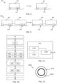
- FIGS 8 and 9 schematically illustrate the definition of virtual axles;
- Figure 8 shows an example 800 with a single vehicle unit 801 supported on three axles and
- Figure 9 illustrates an example 900 where two vehicle units 901, 902 are supported on a total of six axles.
- a vehicle unit 801 has two rear axles 810, they are grouped together and represented by a single virtual axle 820.
- a similar situation is illustrated for the vehicle unit 901 in Figure 9 which also has two rear axles 910.
- a towed vehicle unit 902 with three physical axles 920 grouped together will be modelled as a vehicle unit 902 with a single virtual axle 940 representing the three physical axles 910, as shown in Figure 9 .
- a vertical plane through the CoG may be used to assign physical axles to front or rear vertical axles.
- the location of the at least one virtual axle 820, 930, 940 can be selected such as to be pitch torque equivalent with the corresponding vehicle unit 801, 901, 902.
- An axle roll stiffness for front and rear axles C f , C r , respectively, of the at least one virtual axle may be determined by adding physical roll stiffness of corresponding physical axles.
- a roll center height H rc of the at least one virtual axle may be defined as an average roll center height of the corresponding physical axles.
- F z 2 l r ⁇ m ⁇ g 2 ⁇ L ⁇ m ⁇ h 2 ⁇ L a x + m h ⁇ C f ⁇ L ⁇ H rc ⁇ C f ⁇ l f ⁇ C r ⁇ l r w ⁇ L ⁇ C f + C r a y + H
- the same principles discussed above for determining range for the suspension based estimator can be applied also for the IMU-based estimator, i.e., the second tyre normal force range F z2,min , F z2,max can be determined based on a minimization and on a maximization, respectively, of an expression of tyre force F z based on the IMU data 320, subject to a set of pre-determined constraints on the IMU data 320.
- F z 1 l r ⁇ m ⁇ g 2 ⁇ L ⁇ m ⁇ h ⁇ g 2 ⁇ L a x ⁇ m h ⁇ C f ⁇ L ⁇ H rc ⁇ C f ⁇ l f ⁇ C r ⁇ l r w ⁇ L ⁇ C f + C r a y ⁇ H rc ⁇ J z w ⁇ L ⁇ ⁇ z + C f ⁇ J x w ⁇ C f + C r ⁇ ⁇ x
- the expressions now comprise 5 parameters p 1 -p 5 .
- the second tyre normal force range F z2,min to F z2,max is determined based on a nominal value of tyre force F z obtained based on the IMU data 320, and on a pre-determined perturbation of the IMU data 320.
- Figures 5-7 show details of a vehicle model that can be used to support normal force estimation according to the discussion above.
- Figure 5 shows a side view 500 of a vehicle unit travelling downhill at an angle ⁇ yr .
- Figure 6 shows a rear view of a vehicle at a banking angle ⁇ xr with respect to some reference surface. It is appreciated that, although the relationship between parameters in Figures 5-7 is not explicitly defined herein, the skilled person is able to determine relationships between the different parameters in a straight forward manner.
- the vehicle modelled in Figures 5-7 here has one rigid body and two axles. Each axle has two wheels.
- the body thus has four degrees of freedom: longitudinal and lateral motion in the road plane and roll and yaw angular motion.
- the rolling motion is exhibited around a roll axis defined by roll center heights at the front and rear axle. Note that the body pitch angular degree of freedom is intentionally ignored to not complicate the discussion.
- the suspension is conceptually modelled with a spiral spring at each axle with two axle parameters; roll stiffness and roll center height. Axles are modelled mass less and suspension damping is neglected.
- FIG. 10 is a flow chart illustrating methods which summarize the above discussions. There is shown a method for determining a tyre normal force range F z,min to F z,max of a tyre force F z acting on a vehicle 100.
- the method comprises obtaining S1 suspension data 310 associated with a suspension system of the vehicle 100, and also obtaining S2 inertial measurement unit (IMU) data 320 associated with the vehicle 100.
- IMU inertial measurement unit
- the suspension data 310 comprises an axle length L w or track width w, an axle mass m axle , a suspension compression force value and left and right levelling sensor values.
- the suspension compression value may be a bellow pressure value related to a air suspension compression force F z,bellow , an electromechanical suspension compression value or other compression force value associated with a suspension system of the vehicle 100.
- the method also comprises estimating S3, by a suspension-based estimator 330, a first tyre normal force range F z1,min to F z1,max based on the suspension data 310.
- the first tyre normal force range F z1,min , F z1,max may be determined based on a minimization and on a maximization, respectively, of an expression of tyre force F z based on the suspension data 310, subject to a set of pre-determined constraints on the suspension data 310.
- the first tyre normal force range F z1,min , F z1,max may also be determined based on a nominal value of tyre force F z obtained based on the suspension data 310, and on a pre-determined perturbation of the suspension data 310.
- the method also comprises estimating S4, by an inertial force-based estimator 340, a second tyre normal force range F z2,min to F z2,max based on the IMU data 320.
- estimating the second tyre normal force range also comprises defining S41 at least one virtual vehicle axle 820, 930, 940 for each vehicle unit 801, 901, 902, estimating S42 tyre normal forces for each virtual axle, and allocating S43 the estimated tyre normal forces between the physical axles 810, 910, 920 of the vehicle unit 801, 901, 902.
- the at least one virtual axle 820, 930, 940 is defined S44 based on a center of gravity (CoG) of a corresponding vehicle unit 801, 901, 902.
- CoG center of gravity
- a location of the at least one virtual axle 820, 930, 940 is selected S45 to be pitch torque equivalent with the vehicle unit 801, 901, 902, wherein an axle roll stiffness of the at least one virtual axle is determined by adding physical roll stiffness of corresponding physical axles, and wherein a roll center height of the at least one virtual axle is defined as an average roll center height of the corresponding physical axles.
- allocating the estimated tyre normal forces between the physical axles of the vehicle comprises allocating S46 the estimated tyre normal forces based on a known load quotient between physical axles.
- the second tyre normal force range F z2,min to F z2,max may for example be determined based on a minimization and on a maximization, respectively, of an expression of tyre force F z based on the IMU data 320, subject to a set of pre-determined constraints on the IMU data 320.
- the second tyre normal force range F z2,min to F z2,max may also be determined based on a nominal value of tyre force F z obtained based on the IMU data 320, and on a pre-determined perturbation of the IMU data 320.
- the disclosed method also determines S5 the tyre normal force range F z,min to F z,max based on the first tyre normal force range F z1,min to F z1,max and on the second tyre normal force range F z2,min to F z2,max .
- the disclosed methods may furthermore comprise determining S51 an upper limit F z,max of the tyre normal force range as the largest of the upper limits of the first tyre normal force range F z1,max and the second tyre normal force range F z2,max .
- the disclosed methods may also comprise determining S52 a lower limit F z,min of the tyre normal force range as the smallest of the lower limits of the first tyre normal force range F z1,min and the second tyre normal force range F z2,min .
- the disclosed methods comprise determining S6 an uncertainty value F z,uncertainty associated with the determined tyre normal force range F z,min , F z,max , wherein the uncertainty value is based on a measure of road roughness.
- the measure of road roughness may for example be obtained S61 based on any of; an IMU vertical acceleration value, an IMU pitch-rate value, and on a variation in level sensors of the vehicle suspension system.
- the uncertainty value F z,uncertainty is determined S62 based on a sum of squared measures of road roughness.
- the disclosed methods may also comprise determining S7 a range of vehicle acceleration capabilities a min to a max based on the determined tyre normal force range.
- the disclosed methods may furthermore comprise comprising distributing S8 wheel torque for vehicle operation between wheels of the vehicle 100, based on the determined tyre normal force range F z,min , F z,max for each wheel.
- FIG. 11 schematically illustrates, in terms of a number of functional units, the components of a control unit 101 according to embodiments of the discussions herein.
- This control unit 101 may be comprised in the vehicle 100.
- Processing circuitry 1110 is provided using any combination of one or more of a suitable central processing unit CPU, multiprocessor, microcontroller, digital signal processor DSP, etc., capable of executing software instructions stored in a computer program product, e.g. in the form of a storage medium 1130.
- the processing circuitry 1110 may further be provided as at least one application specific integrated circuit ASIC, or field programmable gate array FPGA.
- the processing circuitry 1110 is configured to cause the control unit 101 to perform a set of operations, or steps, such as the methods discussed in connection to Figure 10 .
- the storage medium 1130 may store the set of operations
- the processing circuitry 1110 may be configured to retrieve the set of operations from the storage medium 1130 to cause the control unit 101 to perform the set of operations.
- the set of operations may be provided as a set of executable instructions.
- the processing circuitry 1110 is thereby arranged to execute methods as herein disclosed.
- the storage medium 1130 may also comprise persistent storage, which, for example, can be any single one or combination of magnetic memory, optical memory, solid state memory or even remotely mounted memory.
- the control unit 101 may further comprise an interface 1120 for communications with at least one external device such as a suspension system sensor or IMU.
- the interface 1120 may comprise one or more transmitters and receivers, comprising analogue and digital components and a suitable number of ports for wireline or wireless communication.
- the processing circuitry 1110 controls the general operation of the control unit 101, e.g., by sending data and control signals to the interface 1120 and the storage medium 1130, by receiving data and reports from the interface 1120, and by retrieving data and instructions from the storage medium 1130.
- Other components, as well as the related functionality, of the control node are omitted in order not to obscure the concepts presented herein.
- Figure 12 illustrates a computer readable medium 1210 carrying a computer program comprising program code means 1220 for performing the methods illustrated in Figure 10 , when said program product is run on a computer.
- the computer readable medium and the code means may together form a computer program product 1200.
Landscapes
- Engineering & Computer Science (AREA)
- Mechanical Engineering (AREA)
- Physics & Mathematics (AREA)
- Transportation (AREA)
- General Physics & Mathematics (AREA)
- Automation & Control Theory (AREA)
- Mathematical Physics (AREA)
- Vehicle Body Suspensions (AREA)
- Control Of Driving Devices And Active Controlling Of Vehicle (AREA)
Claims (23)
- Verfahren zum Bestimmen eines Reifennormalkraftbereichs (Fz,min, Fz,max) einer Reifenkraft (Fz), die auf ein Fahrzeug (100) wirkt, wobei das Verfahren Folgendes umfasst:Erlangen (S1) von Aufhängungsdaten (310), die einem Aufhängungssystem des Fahrzeugs (100) zugeordnet sind;Erlangen (S2) von Trägheitsmesseinheitsdaten, IMU-Daten, (320), die dem Fahrzeug (100) zugeordnet sind;Schätzen (S3), durch einen aufhängungsbasierten Schätzer (330), eines ersten Reifennormalkraftbereichs (Fz1,min, Fz1,max) basierend auf den Aufhängungsdaten (310);Schätzen (S4), durch einen trägheitskraftbasierten Schätzer (340), eines zweiten Reifennormalkraftbereichs (Fz2,min, Fz2,max) basierend auf den IMU-Daten (320); undBestimmen (S5) des Reifennormalkraftbereichs (Fz,min, Fz,max) basierend auf dem ersten Reifennormalkraftbereich (Fz1,min, Fz1,max) und auf dem zweiten Reifennormalkraftbereich (Fz2,min, Fz2,max) .
- Verfahren nach Anspruch 1, wobei die Aufhängungsdaten (310) eine Achslänge (Lw) oder Spurweite (w), eine Achsmasse (mAchse), einen Aufhängungskompressionskraftwert und einen linken und rechten Nivellierungssensorwert umfassen.
- Verfahren nach Anspruch 2, wobei der Aufhängungskompressionswert ein Balgdruckwert (Fz,Balg), ein Kompressionswert einer elektromechanischen Aufhängung oder ein anderer Kompressionskraftwert ist, der einem Aufhängungssystem des Fahrzeugs (100) zugeordnet ist.
- Verfahren nach Anspruch 2 oder 3, wobei der erste Reifennormalkraftbereich (Fz1,min, Fz1,max) basierend auf einer Beziehung

- Verfahren nach einem vorhergehenden Anspruch, wobei der erste Reifennormalkraftbereich (Fz1,min, Fz1,max) basierend auf einer Minimierung bzw. auf einer Maximierung eines Ausdrucks der Reifenkraft (Fz) basierend auf den Aufhängungsdaten (310) unter einem Satz von vorbestimmten Nebenbedingungen an den Aufhängungsdaten (310) bestimmt wird.
- Verfahren nach einem der Ansprüche 1-4, wobei der erste Reifennormalkraftbereich (Fz1,min, Fz1,max) basierend auf einem Nennwert der Reifenkraft (Fz) bestimmt wird, der basierend auf den Aufhängungsdaten (310) und auf einer vorbestimmten Störung der Aufhängungsdaten (310) erlangt wird.
- Verfahren nach einem vorhergehenden Anspruch, wobei das Schätzen des zweiten Reifennormalkraftbereichs Folgendes umfasst:Definieren (S41) mindestens einer virtuellen Fahrzeugachse (820, 930, 940) für jede Fahrzeugeinheit (801, 901, 902);Schätzen (S42) von Reifennormalkräften für jede virtuelle Achse; undZuweisen (S43) der geschätzten Reifennormalkräfte zu den physischen Achsen (810, 910, 920) der Fahrzeugeinheit (801, 901, 902) .
- Verfahren nach Anspruch 7, wobei die mindestens eine virtuelle Achse (820, 930, 940) basierend auf einem Schwerpunkt einer entsprechenden Fahrzeugeinheit (801, 901, 902) definiert (S44) wird.
- Verfahren nach Anspruch 8, wobei eine Stelle der mindestens einen virtuellen Achse (820, 930, 940) so ausgewählt (S45) wird, dass sie das gleiche Nickdrehmoment wie die Fahrzeugeinheit (801, 901, 902) aufweist, wobei eine Achsrollsteifigkeit der mindestens einen virtuellen Achse durch Addieren der physischen Rollsteifigkeit entsprechender physischer Achsen bestimmt wird und wobei eine Rollzentrumshöhe der mindestens einen virtuellen Achse als durchschnittliche Rollzentrumshöhe der entsprechenden physischen Achsen definiert ist.
- Verfahren nach einem der Ansprüche 7-9, wobei das Zuweisen der geschätzten Reifennormalkräfte zu den physischen Achsen des Fahrzeugs Zuweisen (S46) der geschätzten Reifennormalkräfte basierend auf einem bekannten Lastquotienten zwischen physischen Achsen umfasst.
- Verfahren nach einem der Ansprüche 7-10, wobei der zweite Reifennormalkraftbereich (Fz2,min, Fz2,max) basierend auf einer Minimierung bzw. auf einer Maximierung eines Ausdrucks der Reifenkraft (Fz) basierend auf den IMU-Daten (320) unter einem Satz von vorbestimmten Nebenbedingungen an den IMU-Daten (320) bestimmt wird.
- Verfahren nach einem der Ansprüche 7-10, wobei der zweite Reifennormalkraftbereich (Fz2,min, Fz2,max) basierend auf einem Nennwert der Reifenkraft (Fz) bestimmt wird, der basierend auf den IMU-Daten (320) und auf einer vorbestimmten Störung der IMU-Daten (320) erlangt wird.
- Verfahren nach einem vorhergehenden Anspruch, umfassend Bestimmen (S51) einer Obergrenze (Fz,max) des Reifennormalkraftbereichs als die größte der Obergrenzen des ersten Reifennormalkraftbereichs (Fz1,max) und des zweiten Reifennormalkraftbereichs (Fz2,max).
- Verfahren nach einem vorhergehenden Anspruch, umfassend Bestimmen (S52) einer Untergrenze (Fz,min) des Reifennormalkraftbereichs als die kleinste der Untergrenzen des ersten Reifennormalkraftbereichs (Fz1,min) und des zweiten Reifennormalkraftbereichs (Fz2,min).
- Verfahren nach einem vorhergehenden Anspruch, umfassend Bestimmen (S6) eines Unsicherheitswerts (Fz,Unsicherheit), der dem bestimmten Reifennormalkraftbereich (Fz,min, Fz,max) zugeordnet ist, wobei der Unsicherheitswert auf einem Maß der Straßenrauheit basiert.
- Verfahren nach Anspruch 15, wobei das Maß der Straßenrauheit basierend auf beliebigen von Folgendem erlangt (S61) wird: einem IMU-Vertikalbeschleunigungswert, einem IMU-Nickratenwert und einer Variation bei Nivellierungssensoren des Fahrzeugaufhängungssystems.
- Verfahren nach Anspruch 15 oder 16, wobei der Unsicherheitswert (Fz,Unsicherheit) basierend auf einer Summe von quadrierten Maßen der Straßenrauheit bestimmt (S62) wird.
- Verfahren nach einem vorhergehenden Anspruch, umfassend Bestimmen (S7) eines Bereichs von Fahrzeugbeschleunigungsfähigkeiten (amin, amax) basierend auf dem bestimmten Reifennormalkraftbereich.
- Verfahren nach einem vorhergehenden Anspruch, umfassend Verteilen (S8) von Raddrehmoment für den Fahrzeugbetrieb auf Räder des Fahrzeugs (100) basierend auf dem bestimmten Reifennormalkraftbereich (Fz,min, Fz,max) für jedes Rad.
- Computerprogramm (920), umfassend Programmcodemittel zum Durchführen der Schritte nach einem der Ansprüche 1-19, wenn das Programm auf einem Computer oder auf einer Verarbeitungsschaltung (810) einer Steuereinheit (800) ausgeführt wird.
- Computerlesbares Medium (910), das ein Computerprogramm (920) trägt, umfassend Programmcodemittel zum Durchführen der Schritte nach einem der Ansprüche 1-19, wenn das Programmprodukt auf einem Computer oder auf einer Verarbeitungsschaltung (810) einer Steuereinheit (800) ausgeführt wird.
- Steuereinheit (800), die dazu ausgelegt ist, einen Reifennormalkraftbereich einer Reifenkraft zu bestimmen, die auf ein Fahrzeug (100) wirkt, wobei die Steuereinheit (800) dazu konfiguriert ist, die Schritte des Verfahrens nach einem der Ansprüche 1-19 durchzuführen.
- Fahrzeug (100), umfassend eine Steuereinheit (800) nach Anspruch 22.
Applications Claiming Priority (1)
| Application Number | Priority Date | Filing Date | Title |
|---|---|---|---|
| PCT/EP2019/078823 WO2021078371A1 (en) | 2019-10-23 | 2019-10-23 | A method for estimating tyre normal force |
Publications (3)
| Publication Number | Publication Date |
|---|---|
| EP4048986A1 EP4048986A1 (de) | 2022-08-31 |
| EP4048986B1 true EP4048986B1 (de) | 2023-08-02 |
| EP4048986C0 EP4048986C0 (de) | 2023-08-02 |
Family
ID=68382423
Family Applications (1)
| Application Number | Title | Priority Date | Filing Date |
|---|---|---|---|
| EP19794952.2A Active EP4048986B1 (de) | 2019-10-23 | 2019-10-23 | Verfahren zur bestimmung der normalkraft eines reifens |
Country Status (6)
| Country | Link |
|---|---|
| US (1) | US20230150332A1 (de) |
| EP (1) | EP4048986B1 (de) |
| JP (1) | JP2023500059A (de) |
| KR (1) | KR20220082912A (de) |
| CN (1) | CN114945809B (de) |
| WO (1) | WO2021078371A1 (de) |
Families Citing this family (1)
| Publication number | Priority date | Publication date | Assignee | Title |
|---|---|---|---|---|
| CN117610159A (zh) * | 2023-11-23 | 2024-02-27 | 苏州郅荣软件有限公司 | 一种汽车悬置系统稳健性优化方法 |
Family Cites Families (8)
| Publication number | Priority date | Publication date | Assignee | Title |
|---|---|---|---|---|
| DE60022738T8 (de) * | 2000-04-17 | 2006-06-08 | Robert Bosch Gmbh | Vorrichtung und Verfahren zur Bestimmung von Fahrzeugbetriebs-und Dynamikparametern |
| US6549842B1 (en) * | 2001-10-31 | 2003-04-15 | Delphi Technologies, Inc. | Method and apparatus for determining an individual wheel surface coefficient of adhesion |
| US20090177346A1 (en) * | 2007-12-19 | 2009-07-09 | Hac Aleksander B | Dynamic estimation of vehicle inertial parameters and tire forces from tire sensors |
| KR101470221B1 (ko) * | 2013-10-17 | 2014-12-05 | 현대자동차주식회사 | 현가 제어 장치 및 그 방법 |
| US9371073B1 (en) * | 2015-06-19 | 2016-06-21 | GM Global Technology Operations LLC | Real-time determination of tire normal forces |
| US9752962B2 (en) * | 2015-10-09 | 2017-09-05 | The Goodyear Tire & Rubber Company | Robust tire forces estimation system |
| DE102017207248A1 (de) * | 2017-04-28 | 2018-10-31 | Deere & Company | Verfahren zur Ermittlung einer Aufstandskraft an einem Nutzfahrzeug |
| US10207559B2 (en) * | 2017-06-15 | 2019-02-19 | GM Global Technology Operations LLC | Systems and methods for the real-time determination of tire normal forces |
-
2019
- 2019-10-23 US US17/754,878 patent/US20230150332A1/en active Pending
- 2019-10-23 KR KR1020227016923A patent/KR20220082912A/ko unknown
- 2019-10-23 EP EP19794952.2A patent/EP4048986B1/de active Active
- 2019-10-23 WO PCT/EP2019/078823 patent/WO2021078371A1/en unknown
- 2019-10-23 JP JP2022523442A patent/JP2023500059A/ja active Pending
- 2019-10-23 CN CN201980101490.5A patent/CN114945809B/zh active Active
Also Published As
| Publication number | Publication date |
|---|---|
| KR20220082912A (ko) | 2022-06-17 |
| EP4048986C0 (de) | 2023-08-02 |
| EP4048986A1 (de) | 2022-08-31 |
| US20230150332A1 (en) | 2023-05-18 |
| JP2023500059A (ja) | 2023-01-04 |
| WO2021078371A1 (en) | 2021-04-29 |
| CN114945809B (zh) | 2024-01-16 |
| CN114945809A (zh) | 2022-08-26 |
Similar Documents
| Publication | Publication Date | Title |
|---|---|---|
| US6684140B2 (en) | System for sensing vehicle global and relative attitudes using suspension height sensors | |
| US7222007B2 (en) | Attitude sensing system for an automotive vehicle relative to the road | |
| US8095309B2 (en) | GPS assisted vehicular longitudinal velocity determination | |
| USRE40496E1 (en) | Attitude sensing system for an automotive vehicle relative to the road | |
| US6593849B2 (en) | Wheel lift identification for an automotive vehicle | |
| US7451033B2 (en) | Lateral and longitudinal velocity determination for an automotive vehicle | |
| US7600826B2 (en) | System for dynamically determining axle loadings of a moving vehicle using integrated sensing system and its application in vehicle dynamics controls | |
| US7010409B2 (en) | Reference signal generator for an integrated sensing system | |
| CN109606379B (zh) | 一种分布式驱动无人驾驶车辆路径跟踪容错控制方法 | |
| US20040249545A1 (en) | Integrated sensing system for an automotive system | |
| US20090177346A1 (en) | Dynamic estimation of vehicle inertial parameters and tire forces from tire sensors | |
| US10160280B2 (en) | Vehicle yaw motion control method and apparatus using suspension | |
| US20130151075A1 (en) | System and method for vehicle rollover prediction | |
| US20030212482A1 (en) | Method and apparatus for determining lateral velocity of a motor vehicle in closed form for all road and driving conditions | |
| US11639178B2 (en) | Vehicle control method and device | |
| US20040064237A1 (en) | System and method for characterizing vehicle body to road angle for vehicle roll stability control | |
| US20230140485A1 (en) | Architecture and model predictive control-based methodology to manage chassis and driveline actuators | |
| EP4048986B1 (de) | Verfahren zur bestimmung der normalkraft eines reifens | |
| JP2020117196A (ja) | 車両運動状態推定装置 | |
| Singh et al. | Integrated state and parameter estimation for vehicle dynamics control | |
| US20080167777A1 (en) | Method for Controlling the Steering Orientation of a Vehicle | |
| KR102046994B1 (ko) | 노면의 경사도 및 차량의 무게중심 실시간 측정 방법 및 그 장치 | |
| EP3514030A1 (de) | Neigungssteuerungssystem für muldenkipper | |
| CN114312199B (zh) | 车辆侧倾状态确定方法、装置、设备及介质 | |
| CN116279523B (zh) | 一种四轮转向驱动电动汽车状态估计方法 |
Legal Events
| Date | Code | Title | Description |
|---|---|---|---|
| STAA | Information on the status of an ep patent application or granted ep patent |
Free format text: STATUS: UNKNOWN |
|
| STAA | Information on the status of an ep patent application or granted ep patent |
Free format text: STATUS: THE INTERNATIONAL PUBLICATION HAS BEEN MADE |
|
| PUAI | Public reference made under article 153(3) epc to a published international application that has entered the european phase |
Free format text: ORIGINAL CODE: 0009012 |
|
| STAA | Information on the status of an ep patent application or granted ep patent |
Free format text: STATUS: REQUEST FOR EXAMINATION WAS MADE |
|
| 17P | Request for examination filed |
Effective date: 20220517 |
|
| AK | Designated contracting states |
Kind code of ref document: A1 Designated state(s): AL AT BE BG CH CY CZ DE DK EE ES FI FR GB GR HR HU IE IS IT LI LT LU LV MC MK MT NL NO PL PT RO RS SE SI SK SM TR |
|
| DAV | Request for validation of the european patent (deleted) | ||
| DAX | Request for extension of the european patent (deleted) | ||
| GRAP | Despatch of communication of intention to grant a patent |
Free format text: ORIGINAL CODE: EPIDOSNIGR1 |
|
| STAA | Information on the status of an ep patent application or granted ep patent |
Free format text: STATUS: GRANT OF PATENT IS INTENDED |
|
| RIC1 | Information provided on ipc code assigned before grant |
Ipc: G01G 23/00 20060101ALI20230213BHEP Ipc: B60T 8/172 20060101ALI20230213BHEP Ipc: B60T 8/1755 20060101ALI20230213BHEP Ipc: B60W 40/13 20120101ALI20230213BHEP Ipc: B60W 10/22 20060101ALI20230213BHEP Ipc: B60G 17/018 20060101ALI20230213BHEP Ipc: B60G 17/0195 20060101ALI20230213BHEP Ipc: B60T 8/17 20060101ALI20230213BHEP Ipc: G01G 19/08 20060101ALI20230213BHEP Ipc: G01G 19/02 20060101AFI20230213BHEP |
|
| INTG | Intention to grant announced |
Effective date: 20230303 |
|
| GRAS | Grant fee paid |
Free format text: ORIGINAL CODE: EPIDOSNIGR3 |
|
| GRAA | (expected) grant |
Free format text: ORIGINAL CODE: 0009210 |
|
| STAA | Information on the status of an ep patent application or granted ep patent |
Free format text: STATUS: THE PATENT HAS BEEN GRANTED |
|
| AK | Designated contracting states |
Kind code of ref document: B1 Designated state(s): AL AT BE BG CH CY CZ DE DK EE ES FI FR GB GR HR HU IE IS IT LI LT LU LV MC MK MT NL NO PL PT RO RS SE SI SK SM TR |
|
| REG | Reference to a national code |
Ref country code: GB Ref legal event code: FG4D |
|
| REG | Reference to a national code |
Ref country code: CH Ref legal event code: EP |
|
| REG | Reference to a national code |
Ref country code: DE Ref legal event code: R096 Ref document number: 602019034149 Country of ref document: DE |
|
| REG | Reference to a national code |
Ref country code: IE Ref legal event code: FG4D |
|
| U01 | Request for unitary effect filed |
Effective date: 20230901 |
|
| U07 | Unitary effect registered |
Designated state(s): AT BE BG DE DK EE FI FR IT LT LU LV MT NL PT SE SI Effective date: 20230908 |
|
| U20 | Renewal fee paid [unitary effect] |
Year of fee payment: 5 Effective date: 20230905 |
|
| PG25 | Lapsed in a contracting state [announced via postgrant information from national office to epo] |
Ref country code: GR Free format text: LAPSE BECAUSE OF FAILURE TO SUBMIT A TRANSLATION OF THE DESCRIPTION OR TO PAY THE FEE WITHIN THE PRESCRIBED TIME-LIMIT Effective date: 20231103 |
|
| PG25 | Lapsed in a contracting state [announced via postgrant information from national office to epo] |
Ref country code: IS Free format text: LAPSE BECAUSE OF FAILURE TO SUBMIT A TRANSLATION OF THE DESCRIPTION OR TO PAY THE FEE WITHIN THE PRESCRIBED TIME-LIMIT Effective date: 20231202 |
|
| PG25 | Lapsed in a contracting state [announced via postgrant information from national office to epo] |
Ref country code: RS Free format text: LAPSE BECAUSE OF FAILURE TO SUBMIT A TRANSLATION OF THE DESCRIPTION OR TO PAY THE FEE WITHIN THE PRESCRIBED TIME-LIMIT Effective date: 20230802 Ref country code: NO Free format text: LAPSE BECAUSE OF FAILURE TO SUBMIT A TRANSLATION OF THE DESCRIPTION OR TO PAY THE FEE WITHIN THE PRESCRIBED TIME-LIMIT Effective date: 20231102 Ref country code: IS Free format text: LAPSE BECAUSE OF FAILURE TO SUBMIT A TRANSLATION OF THE DESCRIPTION OR TO PAY THE FEE WITHIN THE PRESCRIBED TIME-LIMIT Effective date: 20231202 Ref country code: HR Free format text: LAPSE BECAUSE OF FAILURE TO SUBMIT A TRANSLATION OF THE DESCRIPTION OR TO PAY THE FEE WITHIN THE PRESCRIBED TIME-LIMIT Effective date: 20230802 Ref country code: GR Free format text: LAPSE BECAUSE OF FAILURE TO SUBMIT A TRANSLATION OF THE DESCRIPTION OR TO PAY THE FEE WITHIN THE PRESCRIBED TIME-LIMIT Effective date: 20231103 |
|
| PG25 | Lapsed in a contracting state [announced via postgrant information from national office to epo] |
Ref country code: PL Free format text: LAPSE BECAUSE OF FAILURE TO SUBMIT A TRANSLATION OF THE DESCRIPTION OR TO PAY THE FEE WITHIN THE PRESCRIBED TIME-LIMIT Effective date: 20230802 |
|
| U1N | Appointed representative for the unitary patent procedure changed [after the registration of the unitary effect] |
Representative=s name: STROEM & GULLIKSSON AB; SE |
|
| PG25 | Lapsed in a contracting state [announced via postgrant information from national office to epo] |
Ref country code: ES Free format text: LAPSE BECAUSE OF FAILURE TO SUBMIT A TRANSLATION OF THE DESCRIPTION OR TO PAY THE FEE WITHIN THE PRESCRIBED TIME-LIMIT Effective date: 20230802 |
|
| PG25 | Lapsed in a contracting state [announced via postgrant information from national office to epo] |
Ref country code: SM Free format text: LAPSE BECAUSE OF FAILURE TO SUBMIT A TRANSLATION OF THE DESCRIPTION OR TO PAY THE FEE WITHIN THE PRESCRIBED TIME-LIMIT Effective date: 20230802 Ref country code: RO Free format text: LAPSE BECAUSE OF FAILURE TO SUBMIT A TRANSLATION OF THE DESCRIPTION OR TO PAY THE FEE WITHIN THE PRESCRIBED TIME-LIMIT Effective date: 20230802 Ref country code: ES Free format text: LAPSE BECAUSE OF FAILURE TO SUBMIT A TRANSLATION OF THE DESCRIPTION OR TO PAY THE FEE WITHIN THE PRESCRIBED TIME-LIMIT Effective date: 20230802 Ref country code: CZ Free format text: LAPSE BECAUSE OF FAILURE TO SUBMIT A TRANSLATION OF THE DESCRIPTION OR TO PAY THE FEE WITHIN THE PRESCRIBED TIME-LIMIT Effective date: 20230802 Ref country code: SK Free format text: LAPSE BECAUSE OF FAILURE TO SUBMIT A TRANSLATION OF THE DESCRIPTION OR TO PAY THE FEE WITHIN THE PRESCRIBED TIME-LIMIT Effective date: 20230802 |