EP4048936B1 - Leckdetektion - Google Patents
Leckdetektion Download PDFInfo
- Publication number
- EP4048936B1 EP4048936B1 EP20775181.9A EP20775181A EP4048936B1 EP 4048936 B1 EP4048936 B1 EP 4048936B1 EP 20775181 A EP20775181 A EP 20775181A EP 4048936 B1 EP4048936 B1 EP 4048936B1
- Authority
- EP
- European Patent Office
- Prior art keywords
- hydrogen
- hydrogen storage
- leakage
- pressure
- storage tanks
- Prior art date
- Legal status (The legal status is an assumption and is not a legal conclusion. Google has not performed a legal analysis and makes no representation as to the accuracy of the status listed.)
- Active
Links
Images


Classifications
-
- F—MECHANICAL ENGINEERING; LIGHTING; HEATING; WEAPONS; BLASTING
- F17—STORING OR DISTRIBUTING GASES OR LIQUIDS
- F17C—VESSELS FOR CONTAINING OR STORING COMPRESSED, LIQUEFIED OR SOLIDIFIED GASES; FIXED-CAPACITY GAS-HOLDERS; FILLING VESSELS WITH, OR DISCHARGING FROM VESSELS, COMPRESSED, LIQUEFIED, OR SOLIDIFIED GASES
- F17C13/00—Details of vessels or of the filling or discharging of vessels
- F17C13/02—Special adaptations of indicating, measuring, or monitoring equipment
-
- F—MECHANICAL ENGINEERING; LIGHTING; HEATING; WEAPONS; BLASTING
- F17—STORING OR DISTRIBUTING GASES OR LIQUIDS
- F17C—VESSELS FOR CONTAINING OR STORING COMPRESSED, LIQUEFIED OR SOLIDIFIED GASES; FIXED-CAPACITY GAS-HOLDERS; FILLING VESSELS WITH, OR DISCHARGING FROM VESSELS, COMPRESSED, LIQUEFIED, OR SOLIDIFIED GASES
- F17C5/00—Methods or apparatus for filling containers with liquefied, solidified, or compressed gases under pressures
- F17C5/06—Methods or apparatus for filling containers with liquefied, solidified, or compressed gases under pressures for filling with compressed gases
-
- F—MECHANICAL ENGINEERING; LIGHTING; HEATING; WEAPONS; BLASTING
- F17—STORING OR DISTRIBUTING GASES OR LIQUIDS
- F17C—VESSELS FOR CONTAINING OR STORING COMPRESSED, LIQUEFIED OR SOLIDIFIED GASES; FIXED-CAPACITY GAS-HOLDERS; FILLING VESSELS WITH, OR DISCHARGING FROM VESSELS, COMPRESSED, LIQUEFIED, OR SOLIDIFIED GASES
- F17C2221/00—Handled fluid, in particular type of fluid
- F17C2221/01—Pure fluids
- F17C2221/012—Hydrogen
-
- F—MECHANICAL ENGINEERING; LIGHTING; HEATING; WEAPONS; BLASTING
- F17—STORING OR DISTRIBUTING GASES OR LIQUIDS
- F17C—VESSELS FOR CONTAINING OR STORING COMPRESSED, LIQUEFIED OR SOLIDIFIED GASES; FIXED-CAPACITY GAS-HOLDERS; FILLING VESSELS WITH, OR DISCHARGING FROM VESSELS, COMPRESSED, LIQUEFIED, OR SOLIDIFIED GASES
- F17C2221/00—Handled fluid, in particular type of fluid
- F17C2221/03—Mixtures
- F17C2221/032—Hydrocarbons
- F17C2221/033—Methane, e.g. natural gas, CNG, LNG, GNL, GNC, PLNG
-
- F—MECHANICAL ENGINEERING; LIGHTING; HEATING; WEAPONS; BLASTING
- F17—STORING OR DISTRIBUTING GASES OR LIQUIDS
- F17C—VESSELS FOR CONTAINING OR STORING COMPRESSED, LIQUEFIED OR SOLIDIFIED GASES; FIXED-CAPACITY GAS-HOLDERS; FILLING VESSELS WITH, OR DISCHARGING FROM VESSELS, COMPRESSED, LIQUEFIED, OR SOLIDIFIED GASES
- F17C2250/00—Accessories; Control means; Indicating, measuring or monitoring of parameters
- F17C2250/04—Indicating or measuring of parameters as input values
- F17C2250/0404—Parameters indicated or measured
- F17C2250/043—Pressure
-
- F—MECHANICAL ENGINEERING; LIGHTING; HEATING; WEAPONS; BLASTING
- F17—STORING OR DISTRIBUTING GASES OR LIQUIDS
- F17C—VESSELS FOR CONTAINING OR STORING COMPRESSED, LIQUEFIED OR SOLIDIFIED GASES; FIXED-CAPACITY GAS-HOLDERS; FILLING VESSELS WITH, OR DISCHARGING FROM VESSELS, COMPRESSED, LIQUEFIED, OR SOLIDIFIED GASES
- F17C2250/00—Accessories; Control means; Indicating, measuring or monitoring of parameters
- F17C2250/04—Indicating or measuring of parameters as input values
- F17C2250/0404—Parameters indicated or measured
- F17C2250/0439—Temperature
-
- F—MECHANICAL ENGINEERING; LIGHTING; HEATING; WEAPONS; BLASTING
- F17—STORING OR DISTRIBUTING GASES OR LIQUIDS
- F17C—VESSELS FOR CONTAINING OR STORING COMPRESSED, LIQUEFIED OR SOLIDIFIED GASES; FIXED-CAPACITY GAS-HOLDERS; FILLING VESSELS WITH, OR DISCHARGING FROM VESSELS, COMPRESSED, LIQUEFIED, OR SOLIDIFIED GASES
- F17C2250/00—Accessories; Control means; Indicating, measuring or monitoring of parameters
- F17C2250/04—Indicating or measuring of parameters as input values
- F17C2250/0404—Parameters indicated or measured
- F17C2250/0473—Time or time periods
-
- F—MECHANICAL ENGINEERING; LIGHTING; HEATING; WEAPONS; BLASTING
- F17—STORING OR DISTRIBUTING GASES OR LIQUIDS
- F17C—VESSELS FOR CONTAINING OR STORING COMPRESSED, LIQUEFIED OR SOLIDIFIED GASES; FIXED-CAPACITY GAS-HOLDERS; FILLING VESSELS WITH, OR DISCHARGING FROM VESSELS, COMPRESSED, LIQUEFIED, OR SOLIDIFIED GASES
- F17C2250/00—Accessories; Control means; Indicating, measuring or monitoring of parameters
- F17C2250/04—Indicating or measuring of parameters as input values
- F17C2250/0486—Indicating or measuring characterised by the location
- F17C2250/0491—Parameters measured at or inside the vessel
-
- F—MECHANICAL ENGINEERING; LIGHTING; HEATING; WEAPONS; BLASTING
- F17—STORING OR DISTRIBUTING GASES OR LIQUIDS
- F17C—VESSELS FOR CONTAINING OR STORING COMPRESSED, LIQUEFIED OR SOLIDIFIED GASES; FIXED-CAPACITY GAS-HOLDERS; FILLING VESSELS WITH, OR DISCHARGING FROM VESSELS, COMPRESSED, LIQUEFIED, OR SOLIDIFIED GASES
- F17C2260/00—Purposes of gas storage and gas handling
- F17C2260/03—Dealing with losses
- F17C2260/035—Dealing with losses of fluid
- F17C2260/038—Detecting leaked fluid
-
- F—MECHANICAL ENGINEERING; LIGHTING; HEATING; WEAPONS; BLASTING
- F17—STORING OR DISTRIBUTING GASES OR LIQUIDS
- F17C—VESSELS FOR CONTAINING OR STORING COMPRESSED, LIQUEFIED OR SOLIDIFIED GASES; FIXED-CAPACITY GAS-HOLDERS; FILLING VESSELS WITH, OR DISCHARGING FROM VESSELS, COMPRESSED, LIQUEFIED, OR SOLIDIFIED GASES
- F17C2265/00—Effects achieved by gas storage or gas handling
- F17C2265/06—Fluid distribution
- F17C2265/065—Fluid distribution for refuelling vehicle fuel tanks
-
- F—MECHANICAL ENGINEERING; LIGHTING; HEATING; WEAPONS; BLASTING
- F17—STORING OR DISTRIBUTING GASES OR LIQUIDS
- F17C—VESSELS FOR CONTAINING OR STORING COMPRESSED, LIQUEFIED OR SOLIDIFIED GASES; FIXED-CAPACITY GAS-HOLDERS; FILLING VESSELS WITH, OR DISCHARGING FROM VESSELS, COMPRESSED, LIQUEFIED, OR SOLIDIFIED GASES
- F17C2270/00—Applications
- F17C2270/01—Applications for fluid transport or storage
- F17C2270/0134—Applications for fluid transport or storage placed above the ground
- F17C2270/0139—Fuel stations
-
- Y—GENERAL TAGGING OF NEW TECHNOLOGICAL DEVELOPMENTS; GENERAL TAGGING OF CROSS-SECTIONAL TECHNOLOGIES SPANNING OVER SEVERAL SECTIONS OF THE IPC; TECHNICAL SUBJECTS COVERED BY FORMER USPC CROSS-REFERENCE ART COLLECTIONS [XRACs] AND DIGESTS
- Y02—TECHNOLOGIES OR APPLICATIONS FOR MITIGATION OR ADAPTATION AGAINST CLIMATE CHANGE
- Y02E—REDUCTION OF GREENHOUSE GAS [GHG] EMISSIONS, RELATED TO ENERGY GENERATION, TRANSMISSION OR DISTRIBUTION
- Y02E60/00—Enabling technologies; Technologies with a potential or indirect contribution to GHG emissions mitigation
- Y02E60/30—Hydrogen technology
- Y02E60/32—Hydrogen storage
-
- Y—GENERAL TAGGING OF NEW TECHNOLOGICAL DEVELOPMENTS; GENERAL TAGGING OF CROSS-SECTIONAL TECHNOLOGIES SPANNING OVER SEVERAL SECTIONS OF THE IPC; TECHNICAL SUBJECTS COVERED BY FORMER USPC CROSS-REFERENCE ART COLLECTIONS [XRACs] AND DIGESTS
- Y02—TECHNOLOGIES OR APPLICATIONS FOR MITIGATION OR ADAPTATION AGAINST CLIMATE CHANGE
- Y02P—CLIMATE CHANGE MITIGATION TECHNOLOGIES IN THE PRODUCTION OR PROCESSING OF GOODS
- Y02P90/00—Enabling technologies with a potential contribution to greenhouse gas [GHG] emissions mitigation
- Y02P90/45—Hydrogen technologies in production processes
Definitions
- the present invention relates to detection of leakages in a hydrogen refuelling station.
- the invention further relates to a hydrogen refuelling station.
- Hydrogen refuelling stations are used for filling hydrogen fuel cell vehicles with hydrogen fuel by leading hydrogen from hydrogen storage tanks to dispensers arranged to engage with the hydrogen fuel cell vehicle such that the hydrogen fuel may be transferred to the vehicle tank.
- US2006283237 disclose a system for evaluating leak tightness to a gas storage device of a filling station.
- the system comprises a pressure measure device, a processor and a display.
- an unit for comparing pleasured pressures are comparing measured pressures to a threshold value to determine if any gas is leaking from the gas storage device.
- the hydrogen storage tanks of the hydrogen refuelling station may typically store hydrogen fuel at high pressures in order to meet customer demands, however storing hydrogen at such pressures involves safety concerns.
- a leakage in a hydrogen storage tank results in hydrogen, which is highly flammable, being vented to the surroundings of the hydrogen refuelling station, and this could be detrimental to the safety of people surrounding the hydrogen refuelling station.
- the inventors have identified the above-mentioned issue related to storing hydrogen at high pressure, and subsequently made the below-described invention which provides for a way of detecting if such a leakage is present and which further provides advantages as described below.
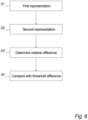
- the invention relates to a method of detecting a leakage in a hydrogen refuelling station comprising a plurality of hydrogen storage tanks, said method comprising the steps of: establishing at a first time a first representation of at least one fluid parameter associated with hydrogen for at least one of said plurality of hydrogen storage tanks; establishing at a second time a second representation of said at least one fluid parameter for said at least one of said plurality of hydrogen storage tanks; the method is characterised in that the at least one fluid parameter is density and wherein the method furthermore comprises the steps of: establishing the density of hydrogen gas in each of a plurality of hydrogen storage tanks, compare the established densities, and indicate the presence of a leakage if at least one of the established densities deviates from the majority of established densities by a deviation threshold value
- a hydrogen refuelling station a piece of infrastructure arranged for filling vehicles with hydrogen fuel in the form of pressurized hydrogen.
- the hydrogen refuelling station may be a part of a station for fossil fuel refuelling or it may be an independent station.
- the hydrogen refuelling station may comprise a production unit, such as an electrolyser unit, which enables the hydrogen refuelling station to produce hydrogen locally.
- hydrogen may be supplied to the hydrogen refuelling station from external sources such as a truck trailer.
- hydrogen storage tank is understood a tank, vessel or container configured for storing hydrogen.
- hydrogen is stored in one or more hydrogen storage tanks, such as a plurality of hydrogen storage tanks, at high pressures.
- hydrogen is stored at high pressures it is possible to store large quantities of hydrogen in a compact volume, and furthermore, the high pressure is of great benefit to the hydrogen refuelling process where the large pressure difference between the hydrogen storage tank of the refuelling station and an empty tank of a vehicle can be used to force hydrogen into the vehicle tank until the two pressures are at equilibrium.
- a cascade refuelling is commonly known as a cascade refuelling.
- the hydrogen refuelling station may use one or more compressors to further increase the pressure of the hydrogen dispensed from the hydrogen storage tanks. This refuelling process including the use of a compressor is commonly known as direct fill.
- Hydrogen is highly flammable and therefore storing large quantities of hydrogen at high pressures is accompanied with safety concerns such as the issue of leakage of hydrogen from hydrogen storage tanks.
- a large cloud of hydrogen gas may form in proximity of the hydrogen storage tank, which when ignited can cause an explosion.
- the hydrogen storage tank itself may also explode, which may cause severe damage to the hydrogen refuelling station and its surroundings. For this reason, it is particularly advantageous to detect if a hydrogen storage tank is leaking.
- an operator and/or a user of the hydrogen refuelling station may be appropriately warned about the level of danger. Furthermore, the hydrogen refuelling station may also cease its operation in response to a detected leakage.
- a leakage in a hydrogen storage tank may be detectable by a change in one at least one fluid parameter associated with the hydrogen stored in the hydrogen storage tank, such as two or more fluid parameters associated with the hydrogen stored in the hydrogen storage tank.
- Such fluid parameters may comprise pressure, temperature, density and any other physical/chemical parameters from which the beforementioned parameters may be derived from.
- Said at least one fluid parameter associated with stored hydrogen may be directly established or indirectly established through establishment of a fluid parameter associated with the immediate surroundings of the hydrogen storage tank.
- the ambient air temperature at the location of the hydrogen storage tank may affect the temperature of the stored hydrogen gas, and an increase in ambient air temperature, due to e.g. changing weather conditions, may result in an increase in the temperature of the stored hydrogen.
- a leakage in a hydrogen storage tank may be detectable as a decrease in hydrogen pressure over time.
- a decrease in hydrogen pressure may not unambiguously be associated with a leakage since changes in the temperature of hydrogen also affect the hydrogen pressure.
- the temperature of the hydrogen increases so does the pressure of the hydrogen, if no significant leakage of hydrogen is present, and likewise when the temperature of the hydrogen decreases so does the pressure of the hydrogen.
- a reference to the temperature of the hydrogen or the ambient temperature may be needed. For example, if a sudden drop in pressure is detected this may be indicative of a leakage unless a corresponding, and sudden, drop in temperature is also observed.
- said threshold difference is a first threshold difference step of comparing said relative difference with a threshold difference comprises comparing said relative difference with a second threshold difference to detect a leakage.
- the first threshold difference may be used for detection of a small leakage, such as a leakage given by a decrease in hydrogen density exceeding 0.5 percent over 30 minutes.
- a small detected leakage may be an indication of an actual small leakage in a hydrogen storage tank, be due to an instrumental error or due to extraordinary conditions such as sudden changes in temperature.
- An operator of the hydrogen refuelling station may receive a warning of a small leakage such that he/she may continue to monitor the hydrogen refuelling station, and in particular monitor the evolution of the detected leakage over time.
- a leakage is detected when at least one relative difference is outside a range of acceptable values of relative difference, said range being limited in at least one end by said threshold difference.
- the settling time may be in the range of 1 to 20 minutes, such as in the range of 5 to 15 minutes, for example 10 minutes. Alternatively, the settling time may be less than 5 minutes, such as 1 minutes, or less than 1 minutes, such as half a minute.
- said method further comprises receiving said measurements, in the form of sensor data, of said at least one fluid parameter in a memory associated with a controller, such as a programmable logic controller, via a data communication link, wherein said steps of determining a relative difference between said first and second measurement of said at least one fluid parameter is carried out by said controller, wherein said step of comparing said relative difference with said threshold difference to detect a leakage in said at least one hydrogen storage tank is carried out by said controller.
- a controller such as a programmable logic controller
- controller By a controller is understood a microcontroller, computer, PLC controller or programmable logic controller, electro-mechanical controller or any other type of controlling unit comprising a processor.
- This equation is advantageous in that it has the effect, that by applying an initial temperature (e.g. measured at time T1) and a Delta temperature (e.g. difference between measured temperature at T1 and T2) a percentage pressure deviation can be calculated.
- an initial temperature e.g. measured at time T1
- a Delta temperature e.g. difference between measured temperature at T1 and T2
- a leakage is indicated if: ⁇ P LeakCheck > ⁇ P abs then: Pressure decrease by leak wherein ⁇ P LeakCheck is the pressure change established based on measurements of pressure of a storage tank at a first time T1 and a second time T2.
- ⁇ P LeakCheck is the pressure change established based on measurements of pressure of a storage tank at a first time T1 and a second time T2.
- the invention relates to a hydrogen refuelling station comprising: a hydrogen storage module comprising a plurality of hydrogen storage tanks; one or more sensors; a hydrogen station module comprising a compressor; a hydrogen dispensing module in fluid connection with said hydrogen storage module, said hydrogen dispensing module comprising at least one hydrogen dispensing nozzle; wherein said hydrogen storage module is fluidly connected to said hydrogen station module by a first fluid connection, wherein said hydrogen station module is fluidly connected to said hydrogen dispensing module through a second fluid connection; and wherein said hydrogen refuelling station is controlled by a controller arranged to detect a leakage in at least one of said hydrogen storage tanks said hydrogen refuelling station is characterized that said controller is configured for: established density of hydrogen gas in each of a plurality of hydrogen storage tanks, comparison of the established densities, and indicating the presence of a leakage if at least one of the established densities deviates from the majority of established densities by a deviation threshold value or said controller is configured for detecting said leakage
- hydrogen fuel cell vehicles must be refuelled in a hydrogen refuelling station HRS, which are analogous to conventional petrol stations for petrol powered vehicles.
- a hydrogen refuelling station HRS stores large amounts of hydrogen in one or more hydrogen storage tanks HST under high pressure.
- a hydrogen refuelling station HRS could make use of a single hydrogen storage tank HST storing hydrogen at an extremely high pressure, such as well above 1000 bars of pressure, to meet customer demands, e.g. a desired number of refuelling in a single day.
- the hydrogen refuelling station HRS may utilize a plurality of hydrogen storage tanks HST storing hydrogen at lower pressures.
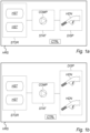
- Fig. 1a shows a hydrogen refuelling station HRS according to an embodiment of the invention.
- the hydrogen refuelling station HRS comprises a hydrogen storage module STOR, a hydrogen station module STAT and a hydrogen dispensing module DISP.
- the hydrogen storage module STOR of this embodiment comprises two hydrogen storage tanks HST, however in other embodiments of the invention the hydrogen storage module STOR may comprise any other number of hydrogen storage tanks HST, such as three or more hydrogen storage tanks HST.
- the hydrogen storage tanks HST are arranged to store hydrogen at a pressure in the range of 0 bar to 1000 bar.
- the hydrogen storage module STOR comprising the hydrogen storage tanks HST, is in fluid connection with the hydrogen station module STAT which comprise at least one compressor arrange to compress stored hydrogen prior to refuelling of a hydrogen fuel cell vehicle.
- hydrogen may be stored in a hydrogen storage tank HST at a pressure of e.g. 500 bar, and the compressor is thus needed for further increasing the hydrogen pressure if the hydrogen is to be dispensed in a hydrogen fuel cell vehicle at e.g. 750 bars of pressure.
- the hydrogen dispensing module DISP comprises a hydrogen dispensing nozzle HDN which facilitates a fluid connection between a hydrogen fuel cell vehicle and the hydrogen refuelling station HRS.
- the hydrogen dispensing nozzle HDN of the hydrogen refuelling station HRS is thus analogous to a fuel dispenser of a conventional petrol station.
- Fig. 1b shows a similar embodiment of the invention, in which the hydrogen dispensing module DISP comprises two hydrogen dispensing nozzles HDN, and in other embodiments of the invention, the hydrogen dispensing module DISP of the hydrogen refuelling station HRS comprises a plurality of hydrogen dispensing nozzles such as three or more hydrogen dispensing nozzles. It should be mentioned that with respect to compressor and cooling capacity, it may be preferred to have only 1, 2 or 3 dispensers connected to one station module.
- the hydrogen refuelling station HRS is operated by a controller CTRL which may control a plurality of valves V (not shown) of the hydrogen refuelling station HRS according to external inputs such as pressure and temperature.
- the controller CTRL is shown as being comprised by the hydrogen refuelling station, however in other embodiments of the invention the controller CTRL may be external from the hydrogen refuelling station HRS, and in such situations the controller CTRL may process e.g. sensor readings externally and communicate instructions for valve operation to the hydrogen refuelling station HRS via e.g. wireless means of connection, such as Wi-Fi, 3G, 4G-LTE and 5G connections.
- Parts of the refilling process of a hydrogen fuel cell vehicle may be performed without use of the compressor COMP.
- the hydrogen content in the vehicle tank may be so low that the pressure in a hydrogen storage tank HST1-HST3 exceeds the pressure of the vehicle tank.
- a pressure difference between a hydrogen storage tank HST1-HST3 and a fuel cell vehicle tank may exist, and this difference in pressure may force hydrogen from a hydrogen storage tank HST1-HST3 to the vehicle tank in parts of the refilling process referred to as a cascade refilling.
- the compressor COMP of the hydrogen station module STAT may be used to further compress stored hydrogen which is referred to as pressure consolidation.
- the hydrogen storage tanks HST1-HST3 may operate at different pressures such that the cascade refilling is undertaken as a sequence of cascade refuelling starting with cascade refuelling from one hydrogen storage tank at one pressure and followed by cascade refuelling from another hydrogen storage tank at a greater pressure.
- the hydrogen pressure in the fuel cell vehicle tank may be ramped up in a number of steps through cascade refuelling until the greatest possible pressure is achieved.
- This cascade refuelling may be followed by refuelling using the compressor if an even greater vehicle tank pressure is needed.
- the desired path of hydrogen from a hydrogen storage tank HST1-HST3 to the hydrogen fuel cell is ensured by one or more valves V of the hydrogen refuelling station HRS.
- the valves V are controlled by a controller CTRL.
- the valve V connecting a hydrogen storage tank HST1-HST3 to the hydrogen station module STAT may be opened to permit flow of hydrogen or closed to block the passage of hydrogen. This is particularly advantageous during cascade refuelling where only a few, e.g. only one, hydrogen storage tank is operated at any given time.
- the valves V may also ensure that the compressor COMP is bypassed during cascade refuelling and that the flow of hydrogen is directed through the compressor COMP when higher refuelling pressures are needed than what can be achieved through cascade refuelling.
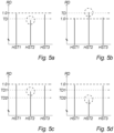
- Figs. 3a-b show embodiments of the invention.
- Fig. 3a illustrates a hydrogen storage module STOR comprising three hydrogen storage tanks HST1-HST3, although any other number of hydrogen storage tanks are conceivable.
- Each of the hydrogen storage tanks HST1-HST3 are connected with a pressure sensor PS arranged to establish at least a representation of the pressure within its respective hydrogen storage tank HST1-HST3.
- the pressure sensors are positioned on one side of the hydrogen storage tanks, however the pressure sensor may be positioned anywhere on or in the hydrogen storage tank or immediately adjacent to the hydrogen storage tanks, for example in piping connecting the hydrogen storage tank to the hydrogen station module STAT.
- the hydrogen refuelling station HRS may also comprise a temperature sensor TS.
- the temperature sensor TS may be an ambient temperature sensor which is arranged to establish a representation of the temperature of the surroundings of the of the hydrogen storage tanks HST1-HST3. Under the assumption of thermal equilibrium between the hydrogen stored in the hydrogen storage tanks and the surroundings, a temperature measurement of an ambient temperature sensor may be representative of the temperature of stored hydrogen.
- each of the hydrogen storage tanks HST1-HST3 comprises a respective temperature sensor TS arranged to establish a representation of the temperature of the hydrogen stored within a hydrogen storage tank.
- the temperature sensors TS are positioned on one side of the hydrogen storage tanks, however the pressure sensor may be positioned anywhere on or in the hydrogen storage tank or immediately adjacent to the hydrogen storage tanks, for example in piping connecting the hydrogen storage tank to the hydrogen station module STAT.
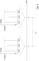
- Fig. 4 shows an embodiment of the invention.
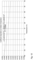
- the drawing illustrates a timeline over which a representation of a fluid parameter is established for hydrogen stored in hydrogen storage tanks HST1-HST3 of a hydrogen refuelling station HRS.
- the fluid parameter is the density of the stored hydrogen.
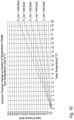
- the density of the hydrogen in the hydrogen storage tanks HST1-HST3 is determined. This determination may be based on measurements of pressure and temperature of the hydrogen, and the determination may be performed by comparing the measurements of temperature and pressure with reference values in a table or graph depicting the density as a function of temperature and pressure. An example of a graph depicting density as a function of pressure is shown in fig. 8 .
- the density of the hydrogen in the first hydrogen storage tank HST1 is about 30 kg/m3 (kilograms per meter cubed) at the first time T1.
- the density of hydrogen in the second hydrogen storage tank HST2 is lower than 30 kg/m3 (kilograms per meter cubed) and the density in the third hydrogen storage tank HST3 is above 30 kg/m3 (kilograms per meter cubed).
- a representation of the density in the same hydrogen storage tanks HST1-HST3 is established.
- the second time T2 occurs at the end of a time period TP starting at the first time T1.
- the density of hydrogen remains the same for the first hydrogen storage tank HST1 and the third hydrogen storage tank HST3, whereas the density of hydrogen has decreased in the second hydrogen storage tank HST2 from the first time T1 to the second time T2, and this may be an indication of a leakage in the second hydrogen storage tank HST2.
- the method of detection of leakage of pressurized gas (in particular hydrogen gas) in a hydrogen refuelling station and particularly in hydrogen storage tanks (HRS) thereof it is important to account for pressure decreases caused by decreasing gas temperature due to an external source, such as ambient temperature "soaking" the pressurized gas volume.
- pressurized gas in particular hydrogen gas
- HRS hydrogen storage tanks
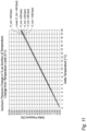
- an absolute temperature change ⁇ T abs is directly corelated with an absolute pressure change ⁇ P abs .
- the trendlines for pressure change diverges.
- One example, that can be established from Fig. 10 is that if the initial pressure in a vessel is 1000bar, then the pressure in the vessel change 15bar, if the temperature changes 4°C.
- ⁇ P % a ⁇ T init 2 + b ⁇ T init + c ⁇ ⁇ T abs
- the time period between time T1 and time T2 should be chosen based on considerations of which kind of leakage should be detected. Hence in a non-limiting example, if the purpose is to detect minor leakages, the time between T1 and T2 should be short e.g. measured in minutes below 1 hour such as 10 to 15 minutes, whereas if large leakages are to be detected, the time period between T1 and T2 should be longer e.g. measured in hours below 2 hours.
- a non-limiting example of what could lead to a minor leakage is worn components and a non-limiting example of what could lead to a large leakage is a hole in a pipe or vessel. Hence, a minor and larger leakage may occur due to the same fault, error or the like and may be categorized as the one or the other depending on the flow escaping the hydrogen pipe and vessel system.
- a software implementable routine based on the above equations and coefficients, which when executed in a controller of e.g. a hydrogen refuelling station, can carrying out a leak check of a pressurized gas volume such as the hydrogen storage tank.
- Such software implementable routine is able to qualify whether a measured pressure decrease established during a leak check ( ⁇ P LeakCheck ) is caused by an external temperature factor such as ambient temperature or it is indeed a gas leak.
- ⁇ P LeakCheck is determined as the pressure difference between measurements of pressure made at time T1 and time T2. Hence: if ⁇ P LeakCheck ⁇ ⁇ P abs then: Pressure decrease by external factor, and if ⁇ P LeakCheck > ⁇ P abs then: Pressure decrease by leak!
- a leakage detection method as describe above can be used to determine if one single storage tank is leaking, however the validity of the method is increased if the leakage detection method is used to determine pressure change of a plurality of different storage tanks and compare these pressure changes to identify outliers.
- said first time and said second time are separated in time by a plurality of predetermined time periods.
- said representation of at least one fluid parameter is said at least one fluid parameter itself.
- said steps of establishing said first and second representation of said at least one fluid parameter comprises measuring said at least one fluid parameter.
- measuring said at least one fluid parameter is understood performing a measurement directly or indirectly on the stored hydrogen in order to establish said at least one fluid parameter.
- said pressure is measured using a pressure sensor connected to said at least one of said plurality of hydrogen storage tanks.
- said pressure is measured for each of said plurality of hydrogen storage tanks using a plurality of pressure sensors, each pressure sensor connected to a respective hydrogen storage tank.
- said at least one fluid parameter comprises temperature
- Measuring the temperature of the hydrogen stored in the hydrogen storage tanks is advantageous when also simultaneously measuring the pressure since it then becomes possible to check whether a change in pressure may be correlated with a change in temperature. Furthermore, measuring the temperature and pressure is advantageous in that it allows for determining a density of the hydrogen.
- said temperature is an ambient temperature measured by at least one temperature sensor positioned externally from said plurality of hydrogen storage tanks.
- a temperature sensor may be located on or in the hydrogen storage tank, or alternatively in immediate fluid connection with the hydrogen storage tank.
- an individual temperature sensor may be located in, or on, piping adjacent to, and in fluid connection with, its corresponding hydrogen storage tank.
- a warning signal is initiated in response to a detected leakage.
- Initiating a warning signal in the form of an alarm signal is advantageous in that users of the hydrogen refuelling station, or other nearby people, may be alerted when a large leakage of hydrogen is detected.
- the warning signal may for example be initiated when a relative difference of a hydrogen storage tank surpasses the second threshold difference.
- the switching from dispensing mode to shutdown mode may be done when a determined relative difference surpasses the second threshold difference.
- said settling time is in the range of 1 to 20 minutes.
- said controller is comprised by said hydrogen refuelling station.
- said predetermined threshold difference is stored in said memory associated with said controller.
- the memory may also be arranged to store said first and second threshold differences. This is advantageous in that the controller may thereby be able to compare a relative difference to said first threshold difference and/or said second threshold difference.
- said hydrogen refuelling station comprises a plurality of hydrogen storage tanks, said plurality of hydrogen storage tanks arranged to store hydrogen at a plurality of values of pressure.
- said controller is comprised by said hydrogen refuelling station.
- a temperature sensor may be located on or in the hydrogen storage tank, or alternatively in immediate fluid connection with the hydrogen storage tank.
- an individual temperature sensor may be located in, or on, piping adjacent to, and in fluid connection with, its corresponding hydrogen storage tank.
- each of said plurality of hydrogen storage tanks is connected to a temperature sensor.
- Having two dispensing nozzles is advantageous in that it enables for simultaneous refuelling of vehicles.
- said hydrogen storage module and said hydrogen station module are physically separated from each other.
- Disposing the second fluid connection at least partly underground is advantageous in that hydrogen flowing from the hydrogen station module to the hydrogen dispensing module is not unnecessarily subjected to weather. For practical reasons, and in order to achieve low refuelling times, it is desirable to have the hydrogen at a low temperature during refuelling, and therefore heating induced by the sun is best avoided. When a fluid line is submerged in the ground it is not nearly as susceptible to heating from the sun, and the temperature of the soil is generally lower than the temperature over ground which may also change rapidly with changing weather conditions.
- a further advantage of having the second fluid connection disposed at least partly underground is that the risk of the second fluid line being run over or crashed into by a vehicle is reduced.
- said hydrogen refuelling station further comprises a cooling unit.
- the hydrogen should be stored at a high pressure in a vehicle tank. This of course, imposes great requirements to the equipment at the station and in the vehicle.
- Another challenge is during refuelling, the hydrogen gas temperature will increase due to two physical phenomena: 1) reverse Joule-Thomson effect during isenthalpic expansion through valves in the refuelling system, and 2) heat of compression in the vehicle tank, i.e. as a vehicle tank is filled with hydrogen (either through cascade refuelling or refuelling using a compressor) the pressure and temperature increases as a function of enthalpy growth. For this reason, it is advantageous to have a cooling unit.
- said cooling unit is arranged in said hydrogen station module.
- the hydrogen refuelling station may comprise a plurality of hydrogen storage tanks arranged to store hydrogen at different pressure levels.
- a hydrogen refuelling station may comprise a first hydrogen storage tank rated at a pressure of 200 bar and a second hydrogen storage tank rated at a pressure of 500 bar.
- the deviation threshold value is at least 5%, preferably 3% and most preferably 2%. Having a deviation threshold value between 5% and 1%, such as e.g. 2.% of the deviating fluid parameter, is advantageous in that it has the effect, that leakages are not indicated based on differences in calibration of sensors etc.
- the controller is configured to indicate a leakage by changing at least one output of an I/O module associated with the controller. This is advantageous in that it has the effect, that the hydrogen refueling station can be turned off in case the controller indicates a leakage.
- the controller in addition to changing an output, the controller also communicates to a controller external to the hydrogen refueling station.
- the controller is configured to detect leakage of hydrogen storage tanks between two subsequent vehicle refuelings. This is advantageous in that it has the effect, that the leakage detection is facilitated 24 hours a day.
- the present invention relates to determining if a hydrogen storage tank comprising e.g. hydrogen gas or other gaseous fluids are leaking. More specific, by monitoring change of pressure inside each of a plurality of hydrogen storage tanks and compare these measured pressure values, it is possible to determine if pressure in one tank deviates from the pressure in the majority of tanks. If this is the case, a leakage is indicated. If not, pressure changes in the tanks may relate to change in ambient temperature.
Landscapes
- Engineering & Computer Science (AREA)
- Mechanical Engineering (AREA)
- General Engineering & Computer Science (AREA)
- Filling Or Discharging Of Gas Storage Vessels (AREA)
Claims (12)
- Verfahren zum Erkennen einer Leckage in einer Wasserstofftankstelle (HRS), die eine Vielzahl von Wasserstoffspeicherungstanks (HST) umfasst, wobei das Verfahren die folgenden Schritte umfasst:Erstellen einer ersten Darstellung von mindestens einem Wasserstoff zugeordneten Fluidparameter für mindestens einen der Vielzahl von Wasserstoffspeicherungstanks (HST) zu einem ersten Zeitpunkt (T1);Erstellen einer zweiten Darstellung des mindestens einen Fluidparameters für den mindestens einen der Vielzahl von Wasserstoffspeicherungstanks (HST) zu einem zweiten Zeitpunkt (T2);das Verfahren ist dadurch gekennzeichnet, dass der mindestens eine Fluidparameter die Dichte ist, und wobei das Verfahren darüber hinaus die folgenden Schritte umfasst:• Ermitteln der Dichte des Wasserstoffgases in jedem einer Vielzahl von Wasserstoffspeicherungstanks,• Vergleichen der ermittelten Dichten, und• Angeben des Vorhandensein einer Leckage, wenn mindestens eine der ermittelten Dichten um einen Abweichungsschwellenwert von der Mehrheit der ermittelten Dichten abweicht.
- Verfahren zum Erkennen einer Leckage nach Anspruch 1, wobei jeder Schritt des Ermittelns des mindestens einen Fluidparameters das Ermitteln des mindestens einen Fluidparameters für jeden der Vielzahl von Wasserstoffspeicherungstanks (HST) umfasst.
- Verfahren zum Erkennen einer Leckage nach Anspruch 2, wobei der Schritt des Bestimmens einer relativen Differenz (RD) zwischen der ersten und der zweiten Darstellung des mindestens einen Fluidparameters das Bestimmen der relativen Differenz (RD) zwischen der ersten und der zweiten Darstellung des mindestens einen Fluidparameters für jeden der Vielzahl von Wasserstoffspeicherungstanks (HST) umfasst.
- Verfahren zum Erkennen einer Leckage nach Anspruch 2, wobei der Schritt des Vergleichens der relativen Differenz (RD) mit einer Schwellenwertdifferenz (TD) zum Erkennen einer Leckage das Vergleichen der relativen Differenz (RD) mit der Schwellenwertdifferenz (TD) für jeden der Vielzahl von Wasserstoffspeicherungstanks (HST) umfasst.
- Verfahren zum Erkennen einer Leckage nach einem der vorstehenden Ansprüche, wobei die Schwellenwertdifferenz (TD) eine erste Schwellenwertdifferenz (TD1) ist,
wobei der Schritt des Vergleichens der relativen Differenz (RD) mit einer Schwellenwertdifferenz (TD) das Vergleichen der relativen Differenz (RD) mit einer zweiten Schwellenwertdifferenz (TD2) umfasst, um eine Leckage zu erkennen. - Verfahren zum Erkennen einer Leckage nach einem der vorstehenden Ansprüche, wobei die Schwellenwertdifferenz (TD) auf der Grundlage eines Volumens des mindestens einen Wasserstoffspeicherungstanks (HST) und einer Leckagerate vorbestimmt wird.
- Verfahren zum Erkennen einer Leckage nach einem der vorstehenden Ansprüche, wobei eine Leckage erkannt wird, wenn mindestens eine relative Differenz (RD) außerhalb eines Bereichs akzeptabler Werte der relativen Differenz liegt, wobei der Bereich in mindestens einem Ende durch die Schwellenwertdifferenz (TD) begrenzt ist.
- Verfahren zum Erkennen einer Leckage nach einem der vorstehenden Ansprüche, wobei die Schritte zum Erstellen einer Darstellung mindestens eines Fluidparameters nach Ablauf einer Beruhigungszeit durchgeführt werden.
- Verfahren zum Erkennen einer Leckage nach einem der vorstehenden Ansprüche, wobei das Verfahren ferner das Empfangen der Messungen in Form von Sensordaten des mindestens einen Fluidparameters in einem Speicher umfasst, der einer Steuerung (CTRL), wie einer programmierbaren Logiksteuerung, über eine Datenkommunikationsverbindung zugeordnet ist.
- Verfahren zum Erkennen einer Leckage nach Anspruch 1, wobei die Schritte des Bestimmens einer relativen Differenz zwischen der ersten und zweiten Messung des mindestens einen Fluidparameters und
des Vergleichens der relativen Differenz (RD) mit der Schwellenwertdifferenz (TD) zum Erkennen einer Leckage in dem mindestens einen Wasserstoffspeicherungstank (HST) durch die Steuerung (CTRL) durchgeführt werden. - Wasserstofftankstelle (HRS), umfassend:ein Wasserstoffspeicherungsmodul (STOR), das eine Vielzahl von Wasserstoffspeicherungstanks (HST) umfasst;einen oder mehrere Sensoren;ein Wasserstofftankstellenmodul (STAT), das einen Kompressor (COMP) umfasst;ein Wasserstoffabgabemodul (HDM) in Fluidverbindung mit dem Wasserstoffspeicherungsmodul (STOR), wobei das Wasserstoffabgabemodul (DISP) mindestens eine Wasserstoffabgabedüse (HDN) umfasst;wobei das Wasserstoffspeicherungsmodul (STOR) durch eine erste Fluidverbindung fluidisch mit dem Wasserstofftankstellenmodul (STAT) verbunden ist, wobei das Wasserstofftankstellenmodul (STAT) durch eine zweite Fluidverbindung fluidisch mit dem Wasserstoffabgabemodul (DISP) verbunden ist; undwobei die Wasserstofftankstelle (HRS) durch eine Steuerung (CTRL) gesteuert wird, die angeordnet ist, um eine Leckage in mindestens einem der Wasserstoffspeicherungstanks (HST) zu erkennen,die Wasserstofftankstelle (HRS) ist dadurch gekennzeichnet, dass die Steuerung (CTRL) konfiguriert ist für:• eine ermittelte Dichte des Wasserstoffgases in jedem einer Vielzahl von Wasserstoffspeicherungstanks,• einen Vergleich der ermittelten Dichten, und• Angeben des Vorhandenseins einer Leckage, wenn mindestens eine der ermittelten Dichten um einen Abweichungsschwellenwert von der Mehrzahl der ermittelten Dichten abweicht.
- Wasserstofftankstelle (HRS) nach Anspruch 11, wobei die Steuerung (CTRL) angeordnet ist, um unter Verwendung des Verfahrens nach einem der Ansprüche 1 bis 10 eine Leckage in mindestens einem der Wasserstoffspeicherungstanks (HST) zu erkennen.
Applications Claiming Priority (2)
| Application Number | Priority Date | Filing Date | Title |
|---|---|---|---|
| DKPA201970665A DK201970665A1 (en) | 2019-10-25 | 2019-10-25 | Leakage detection |
| PCT/DK2020/050252 WO2021078340A1 (en) | 2019-10-25 | 2020-09-14 | Leakage detection |
Publications (3)
| Publication Number | Publication Date |
|---|---|
| EP4048936A1 EP4048936A1 (de) | 2022-08-31 |
| EP4048936B1 true EP4048936B1 (de) | 2025-07-09 |
| EP4048936C0 EP4048936C0 (de) | 2025-07-09 |
Family
ID=72561547
Family Applications (1)
| Application Number | Title | Priority Date | Filing Date |
|---|---|---|---|
| EP20775181.9A Active EP4048936B1 (de) | 2019-10-25 | 2020-09-14 | Leckdetektion |
Country Status (5)
| Country | Link |
|---|---|
| US (1) | US12313225B2 (de) |
| EP (1) | EP4048936B1 (de) |
| KR (1) | KR20220085830A (de) |
| DK (1) | DK201970665A1 (de) |
| WO (1) | WO2021078340A1 (de) |
Families Citing this family (7)
| Publication number | Priority date | Publication date | Assignee | Title |
|---|---|---|---|---|
| CN112576930B (zh) * | 2020-12-29 | 2025-01-28 | 长江勘测规划设计研究有限责任公司 | 基于全浸式移动车载储氢装置的安全加氢装置及使用方法 |
| DE102023200442A1 (de) | 2023-01-20 | 2024-07-25 | Robert Bosch Gesellschaft mit beschränkter Haftung | Verfahren zum Betreiben einer Tankvorrichtung zum Speichern eines Gastreibstoffs und Tankvorrichtung zum Speichern eines Gastreibstoffs |
| EP4421374A1 (de) * | 2023-02-22 | 2024-08-28 | Linde GmbH | Verfahren zum befüllen eines tanks mit medium |
| DE102023202514A1 (de) | 2023-03-21 | 2024-02-22 | Vitesco Technologies GmbH | Verfahren zum Ermitteln der Funktionstüchtigkeit eines Wasserstoffsensors eines Fahrzeugs |
| US12292007B2 (en) | 2023-09-22 | 2025-05-06 | Pratt & Whitney Canada Corp. | Hydrogen leak detection system for an aircraft propulsion system |
| CN118602277B (zh) * | 2024-08-06 | 2024-11-26 | 陕西黑石绿能能源科技有限公司 | 加氢站的泄漏事件预防控制方法及电子设备、存储介质 |
| CN119374026B (zh) * | 2024-10-25 | 2025-11-18 | 潍柴动力股份有限公司 | 一种车载储氢系统的检测方法及装置 |
Family Cites Families (17)
| Publication number | Priority date | Publication date | Assignee | Title |
|---|---|---|---|---|
| WO2001069340A2 (en) | 2000-03-15 | 2001-09-20 | Gaslow International Limited | Monitoring system |
| FR2887332B1 (fr) | 2005-06-16 | 2007-09-21 | Gaz De France | Procede et systeme d'evaluation de l'etancheite d'un dispositif de stockage de gaz carburant sous haute pression |
| US20080141760A1 (en) * | 2006-12-19 | 2008-06-19 | Gm Global Technology Operations, Inc. | Leak detection in a fuel cell system |
| US8494772B2 (en) | 2007-05-17 | 2013-07-23 | Texaco Inc. | Method for calculating hydrogen storage inventory |
| CN102869970B (zh) | 2010-04-30 | 2015-09-16 | 丰田自动车株式会社 | 燃料泄漏检测装置及检测方法 |
| JP5839546B2 (ja) | 2011-06-30 | 2016-01-06 | 株式会社神戸製鋼所 | 水素ステーション |
| JP6327341B2 (ja) | 2014-05-07 | 2018-05-23 | 日産自動車株式会社 | 燃料ガス充填システム及び燃料ガス充填方法 |
| KR101755805B1 (ko) * | 2015-07-09 | 2017-07-07 | 현대자동차주식회사 | 수소연료전지 차량의 수소탱크 내 리크 감지 장치 및 방법 |
| JP2017026599A (ja) * | 2015-07-22 | 2017-02-02 | パナソニックIpマネジメント株式会社 | 水素ガス検査方法および水素ガス検査装置 |
| JP6514611B2 (ja) * | 2015-09-10 | 2019-05-15 | 本田技研工業株式会社 | ガス充填方法 |
| JP6848784B2 (ja) | 2017-09-22 | 2021-03-24 | トヨタ自動車株式会社 | タンク搭載装置 |
| CN113022331B (zh) * | 2021-03-10 | 2022-06-21 | 北京卡达克科技中心有限公司 | 一种燃料电池车的氢泄漏监测报警方法及系统 |
| US12241424B2 (en) * | 2021-03-23 | 2025-03-04 | General Electric Company | Hydrogen fuel leak detection system |
| EP4184140A1 (de) * | 2021-11-19 | 2023-05-24 | Airbus S.A.S. | Anordnung und verfahren zur detektion eines wasserstofflecks in einem wasserstoffversorgungssystem |
| KR20230088605A (ko) * | 2021-12-10 | 2023-06-20 | 현대자동차주식회사 | 차량의 수소저장시스템 모니터링 장치 및 방법 |
| US20230399986A1 (en) * | 2022-06-09 | 2023-12-14 | General Electric Company | Monitoring systems for hydrogen fueled aircraft |
| US20240079616A1 (en) * | 2022-09-02 | 2024-03-07 | Cummins Inc. | Systems and methods for hydrogen leak detection |
-
2019
- 2019-10-25 DK DKPA201970665A patent/DK201970665A1/en not_active Application Discontinuation
-
2020
- 2020-09-14 WO PCT/DK2020/050252 patent/WO2021078340A1/en not_active Ceased
- 2020-09-14 KR KR1020227017726A patent/KR20220085830A/ko active Pending
- 2020-09-14 EP EP20775181.9A patent/EP4048936B1/de active Active
- 2020-09-14 US US17/771,586 patent/US12313225B2/en active Active
Also Published As
| Publication number | Publication date |
|---|---|
| DK201970665A1 (en) | 2021-07-01 |
| US20220373134A1 (en) | 2022-11-24 |
| KR20220085830A (ko) | 2022-06-22 |
| US12313225B2 (en) | 2025-05-27 |
| WO2021078340A1 (en) | 2021-04-29 |
| EP4048936A1 (de) | 2022-08-31 |
| EP4048936C0 (de) | 2025-07-09 |
Similar Documents
| Publication | Publication Date | Title |
|---|---|---|
| EP4048936B1 (de) | Leckdetektion | |
| KR102551697B1 (ko) | 계량기의 유량계 고장 진단 방법 및 수소 충전 장치 | |
| CA2787670C (en) | Fuel gas station, fuel gas filling system, and fuel gas supplying method | |
| AU2018207266B2 (en) | Device and method for determining the heat insulation quality of dual-wall, vacuum-insulated containers | |
| US6619336B2 (en) | System and method for dispensing pressurized gas | |
| CA2824901C (en) | Cng time fill system and method with safe fill technology | |
| US5551490A (en) | Apparatus and method for controlling the charging of NGV cylinders from natural gas refueling stations | |
| US9939298B2 (en) | Pressure relief detection for use with gas storage | |
| KR20230088157A (ko) | 연료전지차량의 수소 누출 감지 장치 및 방법 | |
| CN110873282A (zh) | 用于运行机动车的方法以及机动车 | |
| JP2006349180A (ja) | 高圧燃料ガス貯蔵装置の気密性評価方法およびシステム | |
| KR101031221B1 (ko) | 가스미터 온압보정장치의 휴대용 검증장치 | |
| EP2796848B1 (de) | Verfahren und System zur Überwachung der Unversehrtheit eines unter Druck stehenden Tanks | |
| CN115917207B (zh) | 流量计故障判定方法和氢填充装置 | |
| CN111502866A (zh) | 用于运行燃料系统的方法以及控制器 | |
| US12152736B2 (en) | System and method for compressed gas dispensing with subsequent venting | |
| KR20250135879A (ko) | 가스 연료를 저장하는 탱크 장치의 작동 방법 및 가스 연료를 저장하는 탱크 장치 | |
| Petitpas | 1,000+ cycles of a 350 bar prototype cryo-compressed pressure vessel | |
| US11906109B2 (en) | Method for displaying a fill level of a pressure vessel, and pressure vessel assembly | |
| KR20250129812A (ko) | 가스 연료를 저장하는 탱크 장치의 작동 방법 및 가스 연료를 저장하는 탱크 장치 | |
| KR20250135854A (ko) | 가스 연료를 저장하는 탱크 장치를 작동시키기 위한 방법 및 가스 연료를 저장하기 위한 탱크 장치 | |
| JP2010116981A (ja) | バルク管理システム |
Legal Events
| Date | Code | Title | Description |
|---|---|---|---|
| STAA | Information on the status of an ep patent application or granted ep patent |
Free format text: STATUS: UNKNOWN |
|
| STAA | Information on the status of an ep patent application or granted ep patent |
Free format text: STATUS: THE INTERNATIONAL PUBLICATION HAS BEEN MADE |
|
| PUAI | Public reference made under article 153(3) epc to a published international application that has entered the european phase |
Free format text: ORIGINAL CODE: 0009012 |
|
| STAA | Information on the status of an ep patent application or granted ep patent |
Free format text: STATUS: REQUEST FOR EXAMINATION WAS MADE |
|
| 17P | Request for examination filed |
Effective date: 20220516 |
|
| AK | Designated contracting states |
Kind code of ref document: A1 Designated state(s): AL AT BE BG CH CY CZ DE DK EE ES FI FR GB GR HR HU IE IS IT LI LT LU LV MC MK MT NL NO PL PT RO RS SE SI SK SM TR |
|
| DAV | Request for validation of the european patent (deleted) | ||
| DAX | Request for extension of the european patent (deleted) | ||
| STAA | Information on the status of an ep patent application or granted ep patent |
Free format text: STATUS: EXAMINATION IS IN PROGRESS |
|
| 17Q | First examination report despatched |
Effective date: 20231222 |
|
| RAP3 | Party data changed (applicant data changed or rights of an application transferred) |
Owner name: CAVENDISH HYDROGEN A/S |
|
| GRAP | Despatch of communication of intention to grant a patent |
Free format text: ORIGINAL CODE: EPIDOSNIGR1 |
|
| STAA | Information on the status of an ep patent application or granted ep patent |
Free format text: STATUS: GRANT OF PATENT IS INTENDED |
|
| INTG | Intention to grant announced |
Effective date: 20250204 |
|
| GRAS | Grant fee paid |
Free format text: ORIGINAL CODE: EPIDOSNIGR3 |
|
| GRAA | (expected) grant |
Free format text: ORIGINAL CODE: 0009210 |
|
| STAA | Information on the status of an ep patent application or granted ep patent |
Free format text: STATUS: THE PATENT HAS BEEN GRANTED |
|
| AK | Designated contracting states |
Kind code of ref document: B1 Designated state(s): AL AT BE BG CH CY CZ DE DK EE ES FI FR GB GR HR HU IE IS IT LI LT LU LV MC MK MT NL NO PL PT RO RS SE SI SK SM TR |
|
| REG | Reference to a national code |
Ref country code: GB Ref legal event code: FG4D |
|
| REG | Reference to a national code |
Ref country code: CH Ref legal event code: EP |
|
| REG | Reference to a national code |
Ref country code: IE Ref legal event code: FG4D |
|
| U01 | Request for unitary effect filed |
Effective date: 20250709 |
|
| U07 | Unitary effect registered |
Designated state(s): AT BE BG DE DK EE FI FR IT LT LU LV MT NL PT RO SE SI Effective date: 20250715 |
|
| U20 | Renewal fee for the european patent with unitary effect paid |
Year of fee payment: 6 Effective date: 20250929 |