EP4048849B1 - Fireproof panel construction for buildings and fireproof glass clamp applied thereby - Google Patents
Fireproof panel construction for buildings and fireproof glass clamp applied thereby Download PDFInfo
- Publication number
- EP4048849B1 EP4048849B1 EP20797197.9A EP20797197A EP4048849B1 EP 4048849 B1 EP4048849 B1 EP 4048849B1 EP 20797197 A EP20797197 A EP 20797197A EP 4048849 B1 EP4048849 B1 EP 4048849B1
- Authority
- EP
- European Patent Office
- Prior art keywords
- base piece
- panel construction
- piece
- fireproof
- construction according
- Prior art date
- Legal status (The legal status is an assumption and is not a legal conclusion. Google has not performed a legal analysis and makes no representation as to the accuracy of the status listed.)
- Active
Links
Images


Classifications
-
- E—FIXED CONSTRUCTIONS
- E06—DOORS, WINDOWS, SHUTTERS, OR ROLLER BLINDS IN GENERAL; LADDERS
- E06B—FIXED OR MOVABLE CLOSURES FOR OPENINGS IN BUILDINGS, VEHICLES, FENCES OR LIKE ENCLOSURES IN GENERAL, e.g. DOORS, WINDOWS, BLINDS, GATES
- E06B3/00—Window sashes, door leaves, or like elements for closing wall or like openings; Layout of fixed or moving closures, e.g. windows in wall or like openings; Features of rigidly-mounted outer frames relating to the mounting of wing frames
- E06B3/04—Wing frames not characterised by the manner of movement
- E06B3/263—Frames with special provision for insulation
- E06B3/26301—Frames with special provision for insulation with prefabricated insulating strips between two metal section members
- E06B3/26303—Frames with special provision for insulation with prefabricated insulating strips between two metal section members with thin strips, e.g. defining a hollow space between the metal section members
-
- E—FIXED CONSTRUCTIONS
- E06—DOORS, WINDOWS, SHUTTERS, OR ROLLER BLINDS IN GENERAL; LADDERS
- E06B—FIXED OR MOVABLE CLOSURES FOR OPENINGS IN BUILDINGS, VEHICLES, FENCES OR LIKE ENCLOSURES IN GENERAL, e.g. DOORS, WINDOWS, BLINDS, GATES
- E06B3/00—Window sashes, door leaves, or like elements for closing wall or like openings; Layout of fixed or moving closures, e.g. windows in wall or like openings; Features of rigidly-mounted outer frames relating to the mounting of wing frames
- E06B3/54—Fixing of glass panes or like plates
- E06B3/5481—Fixing of glass panes or like plates by means of discrete fixing elements, e.g. glazing clips, glaziers points
-
- E—FIXED CONSTRUCTIONS
- E06—DOORS, WINDOWS, SHUTTERS, OR ROLLER BLINDS IN GENERAL; LADDERS
- E06B—FIXED OR MOVABLE CLOSURES FOR OPENINGS IN BUILDINGS, VEHICLES, FENCES OR LIKE ENCLOSURES IN GENERAL, e.g. DOORS, WINDOWS, BLINDS, GATES
- E06B3/00—Window sashes, door leaves, or like elements for closing wall or like openings; Layout of fixed or moving closures, e.g. windows in wall or like openings; Features of rigidly-mounted outer frames relating to the mounting of wing frames
- E06B3/04—Wing frames not characterised by the manner of movement
- E06B3/263—Frames with special provision for insulation
- E06B2003/26394—Strengthening arrangements in case of fire
-
- E—FIXED CONSTRUCTIONS
- E06—DOORS, WINDOWS, SHUTTERS, OR ROLLER BLINDS IN GENERAL; LADDERS
- E06B—FIXED OR MOVABLE CLOSURES FOR OPENINGS IN BUILDINGS, VEHICLES, FENCES OR LIKE ENCLOSURES IN GENERAL, e.g. DOORS, WINDOWS, BLINDS, GATES
- E06B5/00—Doors, windows, or like closures for special purposes; Border constructions therefor
- E06B5/10—Doors, windows, or like closures for special purposes; Border constructions therefor for protection against air-raid or other war-like action; for other protective purposes
- E06B5/16—Fireproof doors or similar closures; Adaptations of fixed constructions therefor
- E06B5/161—Profile members therefor
Definitions
- the present invention relates to a fireproof panel construction.
- the invention more specifically relates to panel constructions with aluminium profiles which are composed of an inner shell made from aluminium on the inside of the building and of an outer shell made from aluminium on the outside of the building, whereby the inner shell and the outer shell are connected by so-called insulating bars which extend in the width direction of the profile to form a thermal break and are made from a heat insulating material for this.
- the profiles are provided with a rebate which forms a seat for the edges of the panel and which is delimited by a supporting wall which extends over the width of the profile around the panel with a certain clearance between the peripheral edge of the panel and the supporting wall.
- the panel is clamped in the rebate by means of glass supports which along the contour of the panel are spread at a distance from each other and which are mounted between the peripheral edges of the panel and the supporting wall of the profiles of the frame.
- the rebate is further delimited by an abutment lip on the outer shell which extends transversely to the supporting wall of the rebate and behind which the edges of the panel are hidden viewed from the outside.
- glazing beads in the form of profiles which are attached from the inside of the building on the inner shells in a mounting groove in the supporting wall provided for this purpose.
- the panel construction is provided with an inner seal and an outer seal, which are mounted on either side of the panel, respectively between the glazing bead and the inner surface of the panel and between the abutment lip and the outer surface of the panel, for which purpose the abutment lip is provided with a sealing groove.
- the specific feature of a fireproof panel construction is that in case of fire the panel must not come loose for a certain period of time when the heat melts and/or deforms the aluminium inner and/or outer shell and/or the insulating bars.
- the glass clamps are executed as two piece clamps with a base piece containing one of the legs and attached to the supporting wall and a clamp piece containing the other leg and is slid and clipped on the base piece upon assembly thus enclosing the panel between said legs.
- Such glass clamps are disclosed in DE102015118156A and DE202006004606U1 .
- holes are drilled in the supporting wall in advance, typically two holes per glass clamp, and the base piece is attached to the supporting wall by means of screws which are screwed into the drilled holes.
- a disadvantage of this is that assembling a panel in the frame of such fireproof panel construction is relatively time-consuming and labour-intensive because two holes need to be drilled per glass clamp which subsequently need to be sealed with silicones before screwing the screws in the holes to attach the base piece.
- the base piece is attached or clamped in a groove of the supporting wall additionally included in the design of the profiles specifically to that end.
- water may accumulate in such extra groove, for which it is necessary to provide drainage, for example by locally interrupting a part of the walls of the groove, which again involves a time-consuming extra operation.
- the purpose of the present invention is to provide a solution to one or more of the aforementioned and other disadvantages.
- the invention relates to a fireproof panel construction, constructed from a frame and a panel attached therein, whereby the frame is composed of aluminium profiles which are composed of an outer shell and an inner shell which are connected to each other by means of insulating bars and which are provided with a rebate which is delimited by a supporting wall which extends in the width direction of the profiles and by an abutment lip which is provided on the outer shell and extends transversely to the supporting wall, whereby along the contour of the panel glass clamps made from a fireproof material are provided at a distance from each other which are attached to the profiles and are provided with a U-shaped piece with two legs between which the panel is enclosed along an edge, whereby the glass clamps are composed of a base piece containing one said leg and attached to a supporting wall and of a clamp piece containing the other leg and attached to the base piece, whereby the abutment lip along the rebate side is provided with an undercut system groove, characterised in that the base piece is executed with a clip part with which one end of
- An advantage of the invention is that for mounting the glass clamps in the rebate of the profiles, putting holes and screws in the profiles is completely unnecessary and consequently the disadvantages connected to holes and screws in the profiles can be completely excluded.
- a profile detail can be used with which the inner shell of the known profiles is standard equipped, such that in the design of the profiles no extra attention needs to be paid to this.
- conventional profiles are provided with one or more ribs with a bent free end on the inner shell, for example to delimit one or more undercut grooves.
- the base piece is clipped to such rib with a clip part.
- the anchoring part is executed with a base with two opposite edges with which the anchoring part is attached to the abutment lip behind the undercut edges of the system groove.
- Such anchoring part therefore uses the existing system groove of the applicant's standard profiles such that no special profile for fireproof panel constructions needs to be provided.
- the base of the anchoring part viewed in the width direction, possesses a narrow dimension which is narrower than the width of the opening of the system groove on the abutment lip and on the level of said opposite edges possesses a wide dimension which is wider than said opening and is sized such that the base can be inserted with its narrow dimension in the longitudinal direction of the system groove and subsequently by rotation over a certain angle can be attached with its opposite edges behind the undercut edges of the system groove.
- said opposite edges of the base of the anchoring part are connected by a bridge which in a mounted condition of the anchoring part together with the abutment lip delimits a channel in the longitudinal direction of the system groove and the base piece of the glass clamps is provided with a hook-shaped protrusion which in said channel hooks behind the anchoring part.
- the base piece with the opposite end of the clip part can be easily attached without screws or holes in the rebate of the profiles by hooking into the channel behind the attachment part.
- the hook-shaped protrusion is part of the lip of the base piece or is formed by it such that no extra equipment is needed for the hook-shaped part.
- the base piece is provided with two supports with which it rests on the supporting wall of the rebate, bridging the swelling tape on the supporting wall with one support resting on the inner shell and the other leg resting on the outer shell.
- the base piece can advantageously be made in one piece from a slat-shaped fireproof material such as stainless steel, for example by folding and punching a strip made from this material.
- a slat-shaped fireproof material such as stainless steel
- the invention also relates to a fireproof glass clamp for use in a fireproof panel construction according to the invention with a rebate for a panel which is delimited by a supporting wall and by an abutment lip transverse thereto, whereby the glass clamp is provided with a U-shaped piece with two upright legs and is composed of a base piece containing one said leg and a clamp piece containing the other leg and can be attached to the base piece, characterised in that the base piece is executed with a downward facing clip part at one end with which said end of the base piece can be clipped to a rib of the abutment lip without screws or holes in the abutment lip and that the glass clamp is further provided with an anchoring part with which the other end of the base piece can be attached to the abutment lip.
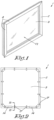
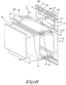
- a fireproof panel construction 1 according to the invention in the form of a leaf of a window is shown in figures 1 to 3 .
- the panel construction 1 is constructed from a frame 2 and a panel attached therein, whereby the frame 2 is composed of hollow aluminium profiles 4 which are composed of an inner shell 4a and an outer shell 4b which are connected to each other by means of insulating bars 4c made from synthetic material or the like, whereby the outer shell is provided with an abutment lip 4d to delimit a rebate 5 for the edges 3a of the panel 3.
- the rebate 5 is delimited by a supporting wall 4e which extends in the width direction of the profiles 4 and by said abutment lip 4d which extends transversely to said supporting wall 4e.
- the abutment lip 4d along the rebate side 5 is also provided with an undercut system groove 12, the opening of which is delimited in a width direction by two undercut edges 13 in the form of two ribs oriented towards one another.
- the panel 3 is enclosed in the rebate 5 by a series of glass supports 14 which are mounted along the contour of the panel 3 at a distance from each other to support the panel 3 with a gap 15 between the panel 3 and the supporting walls 4e of the rebate 5 of the frame 2.
- Swelling tape 16 is mounted around the panel 3 on the supporting walls 4e on the level of the insulating bars 4c which in case of fire are to seal the gap 15 by swelling under the influence of the heat to prevent that heat and/or flames could penetrate from one side of the panel construction 1 to the other side.
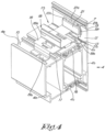
- glass clamps 17 are also mounted between the frame 2 and the panel 3 which are bridgingly attached across the swelling tape 16 to the frame 2 and which contain a U-shaped piece 18 with legs on either side of the panel 3, respectively a leg 18a between the inside 3b of the panel 3 and the glazing beads 9 of the frame 2 and a leg 18b between the outside 3c of the panel 3 and the abutment lip 4d.
- the glass clamps 17 are made from a fireproof material, such as stainless steel, which in case of fire lasts longer than the materials from which the profiles 4 of the frame 2 are made, such as aluminium for the inner and outer shell 4a and 4b and heat-insulating synthetic material for the insulating bars 4c.
- a fireproof material such as stainless steel
- the glass clamps 17 according to the invention are composed of three separate pieces, i.e.:
- the base piece 19 is made of a strip of sheet material, for example steel, and is mounted across the swelling tape 16 and to this end is provided with two supports 19a and 19b with which the base piece 19 supports on the abutment 4e in the rebate 5, respectively a first support 19a at a first end with which the base piece 19 supports on the inner shell 4a and a second support 19b supporting on the abutment 4e of the outer shell 4b.
- a downward facing clip part 19c is provided with a barb 19d oriented toward the first support 19a which together with the first support 19e forms a clip with which the first end of the base piece 19 can be hooked over the T-shaped rib 11 without having to screw or drill holes.
- the second end of the base piece 19 is bent right-angledly in the direction away from the supports 19a and 19b to form said leg 18b of the U-shaped piece 18 between the panel 3 and the abutment lip 4d.
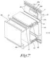
- This bent end 18b is detached over a certain width of the base piece 19 from the rest of the base piece 19 to form a hook-shaped protrusion 19f with which the base piece 19 can be or is hooked behind the anchoring part 21 as shown in the figures 3 and 4 and figure 11 .
- the free end 19f of the hook-shaped piece 19e is bent along a small length in the direction of the first support 19a of the basic element 19.
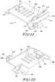
- the anchoring part 21 contains a base 21a with two opposite edges 21b with which the anchoring part 21 can be, or is, attached behind the undercut edges 13 of the system groove 12.
- said base 21a of the anchoring part 21 possesses a narrow dimension 3 which is narrower than the width A of the opening of the system groove 12 on the abutment lip 4d and possesses a wide dimension C on the level of said opposite edges 21a which is wider than said opening.
- the anchoring part 21 is sized such that the base 21a can be inserted with its narrow dimension B in the longitudinal direction of the system groove 12 as shown in figure 6 and subsequently, as shown with arrow R in figure 6 , by rotation over a certain angle can be attached with its opposite edges 21b behind the undercut edges 13 of the system groove 12 as shown in figure 7 .
- the body of the anchoring part 21 is formed by a bridge 21c which connects said edges 21b to each other and which in a mounted condition of the anchoring part 21 together with the base of the system groove 12 on the abutment lip 4e delimits a channel 22 which extends in the longitudinal direction of the system groove 12.
- the anchoring part 21 is provided with a seal 21d at the side facing away from the abutment lip 4e.
- the base piece 19 shown in the example is made in one piece, based on a slat made from a fireproof material.
- the first support 19a is obtained by double folding an end of the slat along a certain length downwards.
- the leg 18b of the U-shaped piece 18 that is part of the basic element 19 is formed by folding the other end of the slat upward.
- the second support 19b is realised by making an L-shaped incision in the slat along the folding line of said leg 18b and further connecting right-angledly thereon in the longitudinal direction of the slat to form a tongue which is subsequently folded down double and in the example has a width which is approximately half the width of the slat.
- the clip part 19c is formed by an incision for delimiting a lip-shaped part which is folded downward along its base and the free end of which is folded over to form said barb 19d.
- the clamp piece 20 is also formed in one piece from plate material and possesses U-shaped folded side edges 20a with which said clamp piece 20 is slideably mounted over the side edges of the base piece 19.
- the clamp piece 20 is provided with locking means in the known way in the form of a downward angled lip 20b which when sliding the clamp piece 20 on the base piece 19 elastically clicks in a groove 19g of a series of grooves which to this end are provided in different click positions in the base piece 19.
- the assembly of a fireproof glass clamp 17 according to the invention is very simple and as follows.
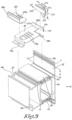
- an anchoring part 21 is mounted in the system groove 12 on the inside of the abutment lip 4e of the frame 2 by screwing in as shown in the figures 6 and 7 .
- a base piece 19 in an upwardly sloping position with the hook-shaped protrusion 19e in the direction of arrow P is hooked behind the anchoring part 21, to subsequently, as shown with arrow Q in figure 9 , let the base piece 19 hinge around the hook-shaped protrusion 19e to clip the clips 19a-19d at the other end over the T-shaped rib 11 as shown in figure 10 .
- the base piece 19 is now anchored to the frame 2, on the one hand with one end to the inner shell 4a and, on the other hand, with the other end to the outer shell 4b and this without drilling or screwing and without having to interrupt the swelling tape 16.
- the panel 3 can be mounted in the frame 2 and fixed in the rebate 5 by means of the glass supports 14.
- clamp pieces 20 of the glass clamps 17 can be slid from the inside of the frame on the mounted base pieces with enclosure of the panel 3 between the legs 18a and 18b of the U-shaped piece 18 of the glass clamps 17.
- the glazing beads 9 with the inner seals 7 can be mounted to finish the fireproof panel construction 1 according to the invention.
- the fireproof glass clamps 17 prevent that the panel 3 can fall out of the frame 2 because it is still held by the glass clamps 17 which remain anchored to the inner shell or to the outer shell on the other side of the fire and which last longer than the shells on the side of the fire.
- the present invention is by no means limited to the embodiments described as an example and shown in the figures, but a fireproof panel construction according to the invention and a fireproof glass clamp 17 applied thereby can be realised in all kinds of forms and dimensions without departing from the scope of the invention.
Landscapes
- Engineering & Computer Science (AREA)
- Civil Engineering (AREA)
- Structural Engineering (AREA)
- Special Wing (AREA)
- Securing Of Glass Panes Or The Like (AREA)
Applications Claiming Priority (2)
| Application Number | Priority Date | Filing Date | Title |
|---|---|---|---|
| BE20195740A BE1027713B1 (nl) | 2019-10-25 | 2019-10-25 | Brandbestendige paneelconstructie voor gebouwen en brandbestendige glasklem daarbij toegepast |
| PCT/IB2020/059917 WO2021079298A1 (en) | 2019-10-25 | 2020-10-22 | Fireproof panel construction for buildings and fireproof glass clamp applied thereby |
Publications (3)
| Publication Number | Publication Date |
|---|---|
| EP4048849A1 EP4048849A1 (en) | 2022-08-31 |
| EP4048849B1 true EP4048849B1 (en) | 2025-03-19 |
| EP4048849C0 EP4048849C0 (en) | 2025-03-19 |
Family
ID=68502784
Family Applications (1)
| Application Number | Title | Priority Date | Filing Date |
|---|---|---|---|
| EP20797197.9A Active EP4048849B1 (en) | 2019-10-25 | 2020-10-22 | Fireproof panel construction for buildings and fireproof glass clamp applied thereby |
Country Status (4)
| Country | Link |
|---|---|
| EP (1) | EP4048849B1 (pl) |
| BE (1) | BE1027713B1 (pl) |
| PL (1) | PL4048849T3 (pl) |
| WO (1) | WO2021079298A1 (pl) |
Families Citing this family (2)
| Publication number | Priority date | Publication date | Assignee | Title |
|---|---|---|---|---|
| JP7570980B2 (ja) * | 2021-06-21 | 2024-10-22 | Ykk Ap株式会社 | 開き窓 |
| CN118815021B (zh) * | 2024-08-27 | 2025-02-07 | 赫曼斯盾(广东)建材科技有限公司 | 一种组合式防火隔热型钢质隔断墙 |
Family Cites Families (3)
| Publication number | Priority date | Publication date | Assignee | Title |
|---|---|---|---|---|
| DE202006004606U1 (de) * | 2006-03-21 | 2006-06-08 | SCHÜCO International KG | Rahmenkonstruktion |
| DE102015118156B4 (de) * | 2015-10-23 | 2018-01-04 | Hörmann KG Eckelhausen | Glashalter, damit versehener Brandschutzabschluss sowie Herstellverfahren |
| DE102018007897A1 (de) * | 2018-10-06 | 2020-04-09 | Hydro Extruded Solutions As | Rahmenelement |
-
2019
- 2019-10-25 BE BE20195740A patent/BE1027713B1/nl active IP Right Grant
-
2020
- 2020-10-22 EP EP20797197.9A patent/EP4048849B1/en active Active
- 2020-10-22 PL PL20797197.9T patent/PL4048849T3/pl unknown
- 2020-10-22 WO PCT/IB2020/059917 patent/WO2021079298A1/en not_active Ceased
Also Published As
| Publication number | Publication date |
|---|---|
| WO2021079298A1 (en) | 2021-04-29 |
| PL4048849T3 (pl) | 2025-06-09 |
| BE1027713B1 (nl) | 2021-05-27 |
| EP4048849A1 (en) | 2022-08-31 |
| EP4048849C0 (en) | 2025-03-19 |
| BE1027713A1 (nl) | 2021-05-20 |
Similar Documents
| Publication | Publication Date | Title |
|---|---|---|
| CA2550101C (en) | Window blind system | |
| US8347939B2 (en) | Corrosion resistant intruder screen | |
| US8550140B2 (en) | Storm window and panel attachment | |
| CA1313744C (en) | J-channel member for siding | |
| EP2013435B1 (en) | A window assembly | |
| EP4048849B1 (en) | Fireproof panel construction for buildings and fireproof glass clamp applied thereby | |
| US9970231B2 (en) | Quick release cladding system for fenestration frames | |
| US5667178A (en) | Bracket assembly for mounting a shade | |
| US11788341B2 (en) | Extruded frame system for glazing | |
| US7340866B1 (en) | Wall adapter | |
| US20110005153A1 (en) | Window and Trim Assembly and Method | |
| EP3995664B1 (en) | Assembly of a screen device and a securing profile for securing a screen casing of this screen device | |
| US4115964A (en) | Windows and method of making the same | |
| US4021980A (en) | Storm window | |
| US20070284065A1 (en) | Mounting brackets for hanging blinds and similar structures | |
| US20240247535A1 (en) | Attachable blind bracket for window | |
| EP2171170B1 (en) | System for fitting window blinds to a conservatory roof | |
| GB2479976A (en) | Blind and curtain fixture | |
| EP4023829B1 (en) | Swelling seal for a fire-resistant façade construction and façade construction equipped therewith | |
| US6305144B1 (en) | Window frame and method | |
| JP6671523B2 (ja) | 建具 | |
| GB2344372A (en) | Retaining device for a glazed unit comprising a bracket and glazing clip | |
| BE1030594B1 (nl) | Getrapt deurpaneel, deurblad met mechanisch bevestigd getrapt deurpaneel, paneelkit en werkwijze voor dergelijk deurblad | |
| CN211899136U (zh) | 一种装饰百叶组件及幕墙 | |
| EP1640547A1 (en) | A method of attaching a cover element to a window casement, and a cover element to be attached to a window casement |
Legal Events
| Date | Code | Title | Description |
|---|---|---|---|
| STAA | Information on the status of an ep patent application or granted ep patent |
Free format text: STATUS: UNKNOWN |
|
| STAA | Information on the status of an ep patent application or granted ep patent |
Free format text: STATUS: THE INTERNATIONAL PUBLICATION HAS BEEN MADE |
|
| PUAI | Public reference made under article 153(3) epc to a published international application that has entered the european phase |
Free format text: ORIGINAL CODE: 0009012 |
|
| STAA | Information on the status of an ep patent application or granted ep patent |
Free format text: STATUS: REQUEST FOR EXAMINATION WAS MADE |
|
| 17P | Request for examination filed |
Effective date: 20220425 |
|
| AK | Designated contracting states |
Kind code of ref document: A1 Designated state(s): AL AT BE BG CH CY CZ DE DK EE ES FI FR GB GR HR HU IE IS IT LI LT LU LV MC MK MT NL NO PL PT RO RS SE SI SK SM TR |
|
| DAV | Request for validation of the european patent (deleted) | ||
| DAX | Request for extension of the european patent (deleted) | ||
| REG | Reference to a national code |
Ref country code: DE Ref legal event code: R079 Free format text: PREVIOUS MAIN CLASS: E06B0003263000 Ipc: E06B0003540000 Ref document number: 602020047998 Country of ref document: DE |
|
| GRAP | Despatch of communication of intention to grant a patent |
Free format text: ORIGINAL CODE: EPIDOSNIGR1 |
|
| STAA | Information on the status of an ep patent application or granted ep patent |
Free format text: STATUS: GRANT OF PATENT IS INTENDED |
|
| RIC1 | Information provided on ipc code assigned before grant |
Ipc: E06B 3/263 20060101ALI20241014BHEP Ipc: E06B 5/16 20060101ALI20241014BHEP Ipc: E06B 3/54 20060101AFI20241014BHEP |
|
| INTG | Intention to grant announced |
Effective date: 20241120 |
|
| GRAS | Grant fee paid |
Free format text: ORIGINAL CODE: EPIDOSNIGR3 |
|
| GRAA | (expected) grant |
Free format text: ORIGINAL CODE: 0009210 |
|
| STAA | Information on the status of an ep patent application or granted ep patent |
Free format text: STATUS: THE PATENT HAS BEEN GRANTED |
|
| AK | Designated contracting states |
Kind code of ref document: B1 Designated state(s): AL AT BE BG CH CY CZ DE DK EE ES FI FR GB GR HR HU IE IS IT LI LT LU LV MC MK MT NL NO PL PT RO RS SE SI SK SM TR |
|
| REG | Reference to a national code |
Ref country code: GB Ref legal event code: FG4D |
|
| REG | Reference to a national code |
Ref country code: CH Ref legal event code: EP |
|
| REG | Reference to a national code |
Ref country code: DE Ref legal event code: R096 Ref document number: 602020047998 Country of ref document: DE |
|
| REG | Reference to a national code |
Ref country code: IE Ref legal event code: FG4D |
|
| U01 | Request for unitary effect filed |
Effective date: 20250402 |
|
| U07 | Unitary effect registered |
Designated state(s): AT BE BG DE DK EE FI FR IT LT LU LV MT NL PT RO SE SI Effective date: 20250409 |
|
| PG25 | Lapsed in a contracting state [announced via postgrant information from national office to epo] |
Ref country code: RS Free format text: LAPSE BECAUSE OF FAILURE TO SUBMIT A TRANSLATION OF THE DESCRIPTION OR TO PAY THE FEE WITHIN THE PRESCRIBED TIME-LIMIT Effective date: 20250619 |
|
| PG25 | Lapsed in a contracting state [announced via postgrant information from national office to epo] |
Ref country code: NO Free format text: LAPSE BECAUSE OF FAILURE TO SUBMIT A TRANSLATION OF THE DESCRIPTION OR TO PAY THE FEE WITHIN THE PRESCRIBED TIME-LIMIT Effective date: 20250619 |
|
| PG25 | Lapsed in a contracting state [announced via postgrant information from national office to epo] |
Ref country code: HR Free format text: LAPSE BECAUSE OF FAILURE TO SUBMIT A TRANSLATION OF THE DESCRIPTION OR TO PAY THE FEE WITHIN THE PRESCRIBED TIME-LIMIT Effective date: 20250319 |
|
| PG25 | Lapsed in a contracting state [announced via postgrant information from national office to epo] |
Ref country code: GR Free format text: LAPSE BECAUSE OF FAILURE TO SUBMIT A TRANSLATION OF THE DESCRIPTION OR TO PAY THE FEE WITHIN THE PRESCRIBED TIME-LIMIT Effective date: 20250620 |
|
| PG25 | Lapsed in a contracting state [announced via postgrant information from national office to epo] |
Ref country code: SM Free format text: LAPSE BECAUSE OF FAILURE TO SUBMIT A TRANSLATION OF THE DESCRIPTION OR TO PAY THE FEE WITHIN THE PRESCRIBED TIME-LIMIT Effective date: 20250319 |
|
| PG25 | Lapsed in a contracting state [announced via postgrant information from national office to epo] |
Ref country code: ES Free format text: LAPSE BECAUSE OF FAILURE TO SUBMIT A TRANSLATION OF THE DESCRIPTION OR TO PAY THE FEE WITHIN THE PRESCRIBED TIME-LIMIT Effective date: 20250319 |
|
| PG25 | Lapsed in a contracting state [announced via postgrant information from national office to epo] |
Ref country code: CZ Free format text: LAPSE BECAUSE OF FAILURE TO SUBMIT A TRANSLATION OF THE DESCRIPTION OR TO PAY THE FEE WITHIN THE PRESCRIBED TIME-LIMIT Effective date: 20250319 |
|
| PG25 | Lapsed in a contracting state [announced via postgrant information from national office to epo] |
Ref country code: SK Free format text: LAPSE BECAUSE OF FAILURE TO SUBMIT A TRANSLATION OF THE DESCRIPTION OR TO PAY THE FEE WITHIN THE PRESCRIBED TIME-LIMIT Effective date: 20250319 |
|
| PG25 | Lapsed in a contracting state [announced via postgrant information from national office to epo] |
Ref country code: IS Free format text: LAPSE BECAUSE OF FAILURE TO SUBMIT A TRANSLATION OF THE DESCRIPTION OR TO PAY THE FEE WITHIN THE PRESCRIBED TIME-LIMIT Effective date: 20250719 |
|
| REG | Reference to a national code |
Ref country code: CH Ref legal event code: U11 Free format text: ST27 STATUS EVENT CODE: U-0-0-U10-U11 (AS PROVIDED BY THE NATIONAL OFFICE) Effective date: 20251101 |
|
| U20 | Renewal fee for the european patent with unitary effect paid |
Year of fee payment: 6 Effective date: 20251027 |