EP4047549B1 - Verfahren und vorrichtung zur bilddetektion und elektronische vorrichtung - Google Patents
Verfahren und vorrichtung zur bilddetektion und elektronische vorrichtung Download PDFInfo
- Publication number
- EP4047549B1 EP4047549B1 EP20890350.0A EP20890350A EP4047549B1 EP 4047549 B1 EP4047549 B1 EP 4047549B1 EP 20890350 A EP20890350 A EP 20890350A EP 4047549 B1 EP4047549 B1 EP 4047549B1
- Authority
- EP
- European Patent Office
- Prior art keywords
- image
- detected image
- light source
- foreground
- determining
- Prior art date
- Legal status (The legal status is an assumption and is not a legal conclusion. Google has not performed a legal analysis and makes no representation as to the accuracy of the status listed.)
- Active
Links
Images


Classifications
-
- G—PHYSICS
- G06—COMPUTING OR CALCULATING; COUNTING
- G06V—IMAGE OR VIDEO RECOGNITION OR UNDERSTANDING
- G06V10/00—Arrangements for image or video recognition or understanding
- G06V10/98—Detection or correction of errors, e.g. by rescanning the pattern or by human intervention; Evaluation of the quality of the acquired patterns
-
- G—PHYSICS
- G06—COMPUTING OR CALCULATING; COUNTING
- G06T—IMAGE DATA PROCESSING OR GENERATION, IN GENERAL
- G06T7/00—Image analysis
- G06T7/0002—Inspection of images, e.g. flaw detection
-
- G—PHYSICS
- G06—COMPUTING OR CALCULATING; COUNTING
- G06T—IMAGE DATA PROCESSING OR GENERATION, IN GENERAL
- G06T7/00—Image analysis
- G06T7/10—Segmentation; Edge detection
- G06T7/11—Region-based segmentation
-
- G—PHYSICS
- G06—COMPUTING OR CALCULATING; COUNTING
- G06T—IMAGE DATA PROCESSING OR GENERATION, IN GENERAL
- G06T7/00—Image analysis
- G06T7/10—Segmentation; Edge detection
- G06T7/136—Segmentation; Edge detection involving thresholding
-
- G—PHYSICS
- G06—COMPUTING OR CALCULATING; COUNTING
- G06T—IMAGE DATA PROCESSING OR GENERATION, IN GENERAL
- G06T7/00—Image analysis
- G06T7/10—Segmentation; Edge detection
- G06T7/194—Segmentation; Edge detection involving foreground-background segmentation
-
- G—PHYSICS
- G06—COMPUTING OR CALCULATING; COUNTING
- G06V—IMAGE OR VIDEO RECOGNITION OR UNDERSTANDING
- G06V10/00—Arrangements for image or video recognition or understanding
- G06V10/20—Image preprocessing
- G06V10/25—Determination of region of interest [ROI] or a volume of interest [VOI]
-
- G—PHYSICS
- G06—COMPUTING OR CALCULATING; COUNTING
- G06V—IMAGE OR VIDEO RECOGNITION OR UNDERSTANDING
- G06V10/00—Arrangements for image or video recognition or understanding
- G06V10/40—Extraction of image or video features
- G06V10/60—Extraction of image or video features relating to illumination properties, e.g. using a reflectance or lighting model
-
- G—PHYSICS
- G06—COMPUTING OR CALCULATING; COUNTING
- G06T—IMAGE DATA PROCESSING OR GENERATION, IN GENERAL
- G06T2200/00—Indexing scheme for image data processing or generation, in general
- G06T2200/24—Indexing scheme for image data processing or generation, in general involving graphical user interfaces [GUIs]
-
- G—PHYSICS
- G06—COMPUTING OR CALCULATING; COUNTING
- G06T—IMAGE DATA PROCESSING OR GENERATION, IN GENERAL
- G06T2207/00—Indexing scheme for image analysis or image enhancement
- G06T2207/10—Image acquisition modality
- G06T2207/10004—Still image; Photographic image
-
- G—PHYSICS
- G06—COMPUTING OR CALCULATING; COUNTING
- G06T—IMAGE DATA PROCESSING OR GENERATION, IN GENERAL
- G06T2207/00—Indexing scheme for image analysis or image enhancement
- G06T2207/10—Image acquisition modality
- G06T2207/10024—Color image
-
- G—PHYSICS
- G06—COMPUTING OR CALCULATING; COUNTING
- G06T—IMAGE DATA PROCESSING OR GENERATION, IN GENERAL
- G06T2207/00—Indexing scheme for image analysis or image enhancement
- G06T2207/20—Special algorithmic details
- G06T2207/20084—Artificial neural networks [ANN]
-
- G—PHYSICS
- G06—COMPUTING OR CALCULATING; COUNTING
- G06T—IMAGE DATA PROCESSING OR GENERATION, IN GENERAL
- G06T2207/00—Indexing scheme for image analysis or image enhancement
- G06T2207/30—Subject of image; Context of image processing
- G06T2207/30168—Image quality inspection
-
- G—PHYSICS
- G06—COMPUTING OR CALCULATING; COUNTING
- G06T—IMAGE DATA PROCESSING OR GENERATION, IN GENERAL
- G06T2207/00—Indexing scheme for image analysis or image enhancement
- G06T2207/30—Subject of image; Context of image processing
- G06T2207/30196—Human being; Person
- G06T2207/30201—Face
Definitions
- This application pertains to the field of electronic technologies, and in particular, to an artificial intelligence (Artificial Intelligence, AI) terminal-based image detection method and apparatus, and an electronic device.
- AI Artificial Intelligence
- an existing mobile terminal for example, a mobile phone, a tablet, or a camera
- an embodiment of this application provides a computer implemented image detection method, including:
- impact of a light source on clarity of the to-be-detected image is determined by performing light source region detection and foreground region detection on the to-be-detected image, to effectively detect whether an image shot in a backlight condition is blurred.
- the determining a blurring degree of the to-be-detected image based on the light source region and the foreground region includes: determining the blurring degree of the to-be-detected image based on a quantity of all pixels in the light source region and a quantity of all pixels in the foreground region.
- the determining the blurring degree of the to-be-detected image based on a quantity of all pixels in the light source region and a quantity of all pixels in the foreground region includes:
- the determining a light source region of the to-be-detected image includes:
- the to-be-detected image is converted to an HSV (Hue, Saturation, Value) color space or an LAB (CIELAB color model) color space through the color space conversion.
- HSV Human, Saturation, Value
- LAB CIELAB color model
- the to-be-detected image may also be converted to another color space to determine the brightness value of each pixel of the to-be-detected image.
- the color space conversion is performed on the to-be-detected image to determine brightness of each pixel, and the light source region of the to-be-detected image can be determined according to a threshold segmentation method, so that the light source region can be accurately and quickly determined, to improve image detection efficiency.
- the determining a foreground region of the to-be-detected image includes:
- the foreground target may be a target having a dynamic feature in the to-be-detected image, for example, a person or an animal, or the foreground target may be a scene that is close to a viewer and that has a static feature, for example, a flower or food.
- the determining a blurring degree of the to-be-detected image based on the light source region and the foreground region includes: determining the blurring degree of the to-be-detected image based on a quantity of all pixels in the light source region and an area of the foreground region.
- the obtaining a to-be-detected image includes:
- the first shooting mode is a Torch mode, in which a flashlight is steady on during photographing
- the second shooting mode is a Flash mode, in which a flashlight flashes during photographing.
- the switching a current shooting mode from the first shooting mode to a second shooting mode is for example specifically:
- An electronic device sends a control instruction to a flashlight module of the electronic device, to switch a flashlight from a steady-on mode to a mode in which the flashlight flashes once during photographing.
- an embodiment of this application provides a terminal device, including a memory, a processor, and a computer program that is stored in the memory and that can be run on the processor.
- the processor executes the computer program, the processor implements steps in the image detection method according to the first aspect.
- an embodiment of this application provides a computer-readable storage medium.
- the computer-readable storage medium stores a computer program.
- steps in the image detection method according to the first aspect are implemented.
- an embodiment of this application provides a computer program product.
- the computer program product runs on a electronic device, the electronic device is enabled to perform the image detection method according to any one of the first aspect or the possible implementations of the first aspect.
- an image detection method in embodiments of this application is mainly used to detect an image shot in a Torch mode, and can be used to switch a current shooting mode from the Torch mode to a Flash mode when it is detected that a to-be-detected image is a blurred image.
- photographing is performed based on different luminous intensities and different light source areas by using a dichotomy, to determine that a luminous intensity of 23 lux and a light source area of 25% are used as critical values for determining whether the image shot in the Torch mode is blurred.
- the light source area is a most important factor that affects whether a foreground is blurred. For a same foreground (a same face in different photos can be approximately considered as the same foreground), if a light source area is larger, impact on clarity of the foreground is greater. If the foreground is large enough and the light source area is small enough, the impact of the light source area on the clarity of the foreground can be ignored.
- a relationship between a light source area and a foreground area is an important parameter for detecting whether feature details of a to-be-detected image are blurred. Whether backlight blur exists in the to-be-detected image can be determined based on light source region detection and foreground region detection. If it is detected that backlight blur exists in the to-be-detected image, the image is not used as an object for evaluating a facial skin status, to improve accuracy of evaluating the facial skin status. It should be noted that the foreground is a person or an object that is in front of a subject or near a front edge in a lens.
- the foreground in embodiments of this application may include a plurality of object types, for example, objects such as a person, a vehicle, a plant, an animal, a building, a ground, a sky, a table, a chair, and a door frame.
- objects such as a person, a vehicle, a plant, an animal, a building, a ground, a sky, a table, a chair, and a door frame.
- the image detection method provided in embodiments of this application may be applied to a terminal device such as an electronic device, a tablet computer, a wearable device, a vehicle-mounted device, an augmented reality (augmented reality, AR) device/a virtual reality (virtual reality, VR) device, a notebook computer, an ultra-mobile personal computer (ultra-mobile personal computer, UMPC), a netbook, or a personal digital assistant (personal digital assistant, PDA).
- a terminal device such as an electronic device, a tablet computer, a wearable device, a vehicle-mounted device, an augmented reality (augmented reality, AR) device/a virtual reality (virtual reality, VR) device, a notebook computer, an ultra-mobile personal computer (ultra-mobile personal computer, UMPC), a netbook, or a personal digital assistant (personal digital assistant, PDA).
- a terminal device such as an electronic device, a tablet computer, a wearable device, a vehicle-mounted device, an augmented reality (augmented reality, AR) device/a virtual reality (vir
- the wearable device may alternatively be a generic term for wearable devices such as glasses, gloves, watches, clothes, and shoes that are developed based on intelligent design of daily wearing by using wearable technologies.
- the wearable device is a portable device that is directly worn on a body or integrated into clothes or an accessory of a user.
- the wearable device is not only a hardware device, but also implements a powerful function through software support, data exchange, and cloud interaction.
- the wearable intelligent device includes full-featured and large-sized devices that can implement all or some of functions without depending on smart electronic devices, for example, smart watches or smart glasses, and devices that focus on only one type of application function and need to be used with other devices such as smart electronic devices, for example, various smart bands or smart jewelry for monitoring physical signs.
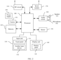
- FIG. 2 is a block diagram of a partial structure of an electronic device according to an embodiment of this application.
- the electronic device includes components such as a radio frequency (Radio Frequency, RF) circuit 110, a memory 120, an input unit 130, a display unit 140, a sensor 150, an audio circuit 160, a wireless fidelity (wireless fidelity, Wi-Fi) module 170, a processor 180, a power supply 190, and a camera 191.
- RF Radio Frequency
- the RF circuit 110 may be configured to: receive and send a signal in an information receiving or sending process or a call process. Particularly, after receiving downlink information from a base station, the RF circuit 110 sends the downlink information to the processor 180 for processing, and sends related uplink data to the base station.
- the RF circuit includes but is not limited to an antenna, at least one amplifier, a transceiver, a coupler, a low noise amplifier (Low Noise Amplifier, LNA), a duplexer, and the like.
- the RF circuit 110 may further communicate with a network and another device through wireless communication.
- the foregoing wireless communication may be any communications standard or protocol, which includes but is not limited to a global system for mobile communications (Global System for Mobile communications, GSM), a general packet radio service (General Packet Radio Service, GPRS), code division multiple access (Code Division Multiple Access, CDMA), wideband code division multiple access (Wideband Code Division Multiple Access, WCDMA), long term evolution (Long Term Evolution, LTE), an email, a short message service (Short Message Service, SMS), and the like.
- GSM Global System for Mobile communications
- GPRS General Packet Radio Service
- CDMA Code Division Multiple Access
- WCDMA wideband code division multiple access
- LTE Long Term Evolution
- SMS short message service
- the memory 120 may be configured to store a software program and a module.
- the processor 180 performs various function applications of the electronic device and data processing by running the software program and the module that are stored in the memory 120.
- the memory 120 may mainly include a program storage region and a data storage region.
- the program storage region may store an operating system, an application required by at least one function (such as a sound playback function or an image playback function), and the like.
- the data storage region may store data (such as audio data or an address book) created based on use of the electronic device, and the like.
- the memory 120 may include a high-speed random access memory, or may include a nonvolatile memory, such as at least one magnetic disk storage device, a flash memory device, or another volatile solid-state storage device.
- the input unit 130 may be configured to: receive entered digit or character information, and generate a key signal input related to a user setting and function control of the electronic device 100.
- the input unit 130 may include a touch panel 131 and another input device 132.
- the touch panel 131 also referred to as a touchscreen, can collect a touch operation performed by the user on or near the touch panel 131 (for example, an operation performed by the user on or near the touch panel 131 by using any proper object or accessory such as a finger or a stylus), and drive a corresponding connection apparatus based on a preset program.
- the touch panel 131 may include two parts: a touch detection apparatus and a touch controller.
- the touch detection apparatus detects a touch location of the user, detects a signal generated by the touch operation, and transfers the signal to the touch controller.
- the touch controller receives touch information from the touch detection apparatus, converts the touch information into touch point coordinates, then sends the touch point coordinates to the processor 180, and can receive and execute a command sent from the processor 180.
- the touch panel 131 may be implemented by using a plurality of types, such as a resistive type, a capacitive type, an infrared ray type, and a surface acoustic wave type.
- the input unit 130 may further include the another input device 132.
- the another input device 132 may include but is not limited to one or more of a physical keyboard, a function key (such as a volume control key or an on/off key), a trackball, a mouse, and a joystick.
- the display unit 140 may be configured to display information entered by the user or information provided for the user, and various menus of the electronic device.
- the display unit 140 may include a display panel 141.
- the display panel 141 may be configured in a form of a liquid crystal display (Liquid Crystal Display, LCD), an organic light-emitting diode (Organic Light-Emitting Diode, OLED), or the like.
- the touch panel 131 may cover the display panel 141. When detecting the touch operation on or near the touch panel 131, the touch panel 131 transfers the touch operation to the processor 180 to determine a type of a touch event, and then the processor 180 provides a corresponding visual output on the display panel 141 based on the type of the touch event.
- touch panel 131 and the display panel 141 are used as two independent parts in FIG. 1 to implement input and input functions of the electronic device, in some embodiments, the touch panel 131 and the display panel 141 may be integrated to implement the input and output functions of the electronic device.
- the electronic device 100 may further include at least one sensor 150 such as a light sensor, a motion sensor, and another sensor.
- the light sensor may include an ambient light sensor and a proximity sensor.
- the ambient light sensor may adjust luminance of the display panel 141 based on brightness of ambient light.
- the proximity sensor may turn off the display panel 141 and/or backlight when the electronic device moves to an ear.
- an accelerometer sensor may detect values of acceleration in all directions (usually, three axes), may detect a value and a direction of gravity when the accelerometer sensor is static, and may be used in an application for recognizing a posture (such as switching between landscape mode and portrait mode, a related game, or magnetometer posture calibration) of the electronic device, a function related to vibration recognition (such as a pedometer or a knock), or the like.
- a posture such as switching between landscape mode and portrait mode, a related game, or magnetometer posture calibration
- a function related to vibration recognition such as a pedometer or a knock
- a gyro a barometer, a hygrometer, a thermometer, or an infrared sensor that may be further disposed on the electronic device, details are not described herein.
- the audio circuit 160, a speaker 161, and a microphone 162 may provide an audio interface between the user and the electronic device.
- the audio circuit 160 may convert received audio data into an electrical signal and then transmit the electrical signal to the speaker 161, and the speaker 161 converts the electrical signal into a sound signal for output.
- the microphone 162 converts a collected sound signal into an electrical signal.
- the audio circuit 160 receives the electrical signal, converts the electrical signal into audio data, and then outputs the audio data to the processor 180 for processing, to send the audio data to, for example, another electronic device through the RF circuit 110, or outputs the audio data to the memory 120 for further processing.
- Wi-Fi belongs to a short distance wireless transmission technology.
- the electronic device may help, by using the Wi-Fi module 170, the user receive and send emails, browse a web page, access streaming media, and the like.
- the Wi-Fi module 170 provides wireless broadband internet access for the user.
- FIG. 1 shows the Wi-Fi module 170, it may be understood that the Wi-Fi module 170 is not a mandatory part of the electronic device 100, and may be omitted based on a requirement without changing the essence of the present invention.
- the processor 180 is a control center of the electronic device.
- the processor 180 is connected to all parts of the entire electronic device by using various interfaces and lines, and performs various functions of the electronic device and data processing by running or executing the software program and/or the module stored in the memory 120 and invoking data stored in the memory 120, to perform overall monitoring on the electronic device.
- the processor 180 may include one or more processing units.
- the processor 180 may integrate an application processor and a modem processor.
- the application processor mainly processes an operating system, a user interface, an application, and the like.
- the modem processor mainly processes wireless communication. It may be understood that the modem processor may not be integrated into the processor 180.
- the electronic device 100 further includes the power supply 190 (for example, a battery) supplying power to all parts.
- the power supply may be logically connected to the processor 180 by using a power management system, to implement functions such as charging management, discharging management, and power consumption management by using the power management system.
- the electronic device 100 may further include a camera 191.
- the camera 191 is configured to capture a static image or a video. An optical image of an object is generated through the lens, and is projected onto a photosensitive element.
- the photosensitive element may be a charge coupled device (charge coupled device, CCD) or a complementary metal-oxide-semiconductor (complementary metal-oxide-semiconductor, CMOS) phototransistor.
- CCD charge coupled device
- CMOS complementary metal-oxide-semiconductor
- the photosensitive element converts an optical signal into an electrical signal, and then transmits the electrical signal to an ISP for converting the electrical signal into a digital image signal.
- the ISP outputs the digital image signal to a DSP for processing.
- the DSP converts the digital image signal into a standard image signal in an RGB format, a YUV format, or the like.
- the camera may be disposed in front or rear of the electronic device 100. This is not limited in this
- the electronic device 100 may include one camera, two cameras, three cameras, and the like. This is not limited in this embodiment of this application.
- the electronic device If the electronic device detects that an image shot in a backlight condition or a frame of image in a preview image in a backlight condition is blurred, the electronic device switches a current shooting mode from the first shooting mode to a second shooting mode, where the first shooting mode is different from the second shooting mode.
- the electronic device if the electronic device detects that the to-be-detected image obtained from the album is blurred in a backlight condition, the electronic device prompts the user to select another image, or re-shoot an image.
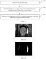
- FIG. 5 is a schematic flowchart of an implementation of an image detection method according to an embodiment of this application.
- the method may be implemented in the electronic device (for example, a mobile phone or a tablet computer) shown in FIG. 2 or FIG. 3 .
- the method may include the following steps.
- the electronic device 100 performs light source region detection on the to-be-detected image to determine the light source region.
- the light source region detection may be: performing color space conversion on the image to obtain a brightness value of each pixel, and determining the light source region according to a threshold segmentation method; and then re-converting the image obtained through the color space conversion to an original color space, detecting a foreground target in the to-be-detected image based on a feature point detection mode, and determining a location of the foreground target in the to-be-detected image, to determine the foreground region.
- the light source region can be determined based on the brightness value of each pixel of the to-be-detected image by using a threshold segmentation method.
- the image is first converted to an HSV (Hue, Saturation, Value) color space or an LAB (CIELAB color model) color space through color space conversion, so that the brightness value of each pixel of the image can be obtained. It may be understood that the image may also be converted to another color space to determine the brightness value of each pixel of the image. This is not limited herein.
- a V value (Value) of each pixel is the brightness value of the pixel.
- the determining a foreground region of the to-be-detected image includes:
- the foreground target may be a target having a dynamic feature in the to-be-detected image, for example, a person or an animal, or the foreground target may be a scene that is close to a viewer and that has a static feature, for example, a flower or food.
- a trained foreground detection model may be used to detect the foreground target in the to-be-detected image.
- the foreground detection model may be a model having a foreground target detection function, such as a single shot multibox detector (Single Shot Multibox Detector, SSD).
- a foreground target for example, a face
- a mode recognition algorithm for example, whether a foreground target (for example, a face) exists in the to-be-detected image is detected by using a mode recognition algorithm, and after it is detected that the foreground target exists, a location of the foreground target in the to-be-detected image is determined by using a target positioning algorithm or a target tracking algorithm.
- the foreground target is determined by performing, based on the foreground detection model, foreground target detection on the to-be-detected image that is converted to the original color space, and then the foreground region is determined based on the location of the foreground target in the to-be-detected image.
- the foreground target is a face image region.
- the foreground detection model may be used to perform face feature detection according to the HIA276 feature point detection method, and then select a foreground region including a face.
- the foreground region detection may be implemented by the neural-network (neural-network, NN) processing unit (NPU) of the electronic device 100.
- the NPU performs facial recognition on the to-be-detected image, selects, by using a rectangle, the foreground region including the face (the foreground target), and automatically outputs an area of the target rectangular region.
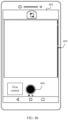
- a rectangular region shown in FIG. 7 is a foreground region, and a specific location of the foreground region can be determined by determining location coordinates of pixels of four vertices of the rectangle in the to-be-detected image.
- the foreground region including the face may alternatively be selected by using a circle, may be selected by using a triangle, or may be selected by using a plurality of shapes such as a pentagon.
- An area of the foreground region can be determined by calculating the area of the rectangular region.
- the location coordinates of the four vertices of the rectangular region are determined, so that a length and a width of the rectangular region are determined, and the area of the rectangular region is determined, that is, the area of the foreground region is obtained.
- the foreground target may alternatively be another object.
- the foreground target is a foam box.
- the blurring degree of the to-be-detected image (that is, the function value of the increasing function of the ratio of the quantity of all pixels in the light source region to the quantity of all pixels in the foreground region) is compared with the predetermined threshold. If the blurring degree of the image is greater than or equal to the predetermined threshold, it is determined that a detection result is that the to-be-detected image is the blurred image. If the blurring degree of the image is less than the predetermined threshold, it is determined that a detection result is that the to-be-detected image is a clear image.
- the predetermined threshold may be a predetermined threshold obtained by performing parameter adjustment after training and testing are performed on a large quantity of sample images, that is, if the blurring degree of the to-be-detected image is greater than or equal to the predetermined threshold, it may be determined that the to-be-detected image is the blurred image.
- traversal optimization may be further performed based on sample images in a training set to search for a trainer or a combination of trainers with a best classification effect, and the trainer or the combination of trainers is used as the image classifier in this embodiment.
- the image classifier is trained and tested based on the sample images to determine the predetermined threshold.
- an AadaBboost method based on a Hhaar feature and an SVM (support vector machine, Support Vector Machine) method For example, an AadaBboost method based on a Hhaar feature and an SVM (support vector machine, Support Vector Machine) method. Specifically, sample images in a training set and sample images in a test set are first constructed. Then, traversal optimization is performed based on the sample images in the training set to search for a trainer or a combination of trainers with a best classification effect, and the trainer or the combination of trainers is used as the image classifier in this embodiment. Finally, classification accuracy of the found image classifier is verified based on the sample images in the test set, and the image classifier can be used after an accuracy requirement (for example, accuracy of 70%) is met. If the requirement is not met, the initial model parameter and the predetermined threshold are adjusted, and the entire process is continuously repeated cyclically until the accuracy requirement is finally met, so that the classifier can determine the predetermined threshold.
- an accuracy requirement for example, accuracy
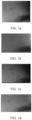
- a detection result corresponding to FIG. 8a is that the image is clear (backlight blur does not exist in the image); and a detection result corresponding to FIG. 8b is that the image is blurred (backlight blur exists in the image).
- the electronic device can automatically perform backlight blur detection on the obtained to-be-detected image, or may perform backlight blur detection after the user taps the first control, to output a corresponding detection result. If it is detected that backlight blur exists in the image, the user is prompted to re-obtain an image, for example, select another image or switch to a Flash mode for photographing again to obtain an image, so as to improve accuracy of facial skin evaluation.
- a detection result corresponding to FIG. 9 is that the image is blurred (backlight blur exists in the image).
- the obtaining a to-be-detected image includes: obtaining a preview frame image in a first shooting mode; and correspondingly, the determining a blurring degree of the to-be-detected image based on the light source region and the foreground region includes: if it is determined, based on the light source region and the foreground region, that the preview frame image is a blurred image, switching a current shooting mode from the first shooting mode to a second shooting mode, where the first shooting mode is different from the second shooting mode.
- the obtained to-be-detected image is the preview frame image in the first shooting mode. Because the preview frame image in the first shooting mode is the blurred image, if the image shot in the first shooting mode is definitely blurred, the current shooting mode needs to be switched from the first shooting mode to the second shooting mode.
- the first shooting mode is a Torch mode
- the second shooting mode is a Flash mode.
- the switching a current shooting mode from the first shooting mode to a second shooting mode is specifically:
- An electronic device 100 sends a control instruction to a flashlight module of the electronic device, to switch a flashlight from a steady-on mode to a mode in which the flashlight flashes once during photographing.
- an artificial intelligence terminal can effectively detect whether an image shot in a backlight condition is blurred, and determine impact of a light source on clarity of the image by performing light source region detection and foreground region detection on the image, to effectively detect whether the image shot in the backlight condition is blurred.
- sequence numbers of the steps do not mean an execution sequence in the foregoing embodiments.
- the execution sequence of the processes should be determined based on functions and internal logic of the processes, and should not constitute any limitation on the implementation processes of the embodiments of this application.
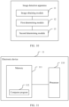
- FIG. 10 is a block diagram of a structure of an image detection apparatus according to an embodiment of this application. For ease of description, only a part related to embodiments of this application are shown.
- the image detection apparatus includes:
- the first determining module 12 includes:
- the first determining module 12 includes:
- the second determining module 13 includes: a third determining unit, configured to determine a blurring degree of the to-be-detected image based on a quantity of all pixels in the light source region and a quantity of all pixels in the foreground region.
- the third determining unit includes:
- the third determining unit is further configured to determine the blurring degree of the to-be-detected image based on the quantity of all pixels in the light source region and an area of the foreground region.
- the image obtaining module 11 includes: a first image obtaining unit, configured to obtain a preview frame image in a first shooting mode.
- the second determining module 13 is further configured to: if it is determined, based on the light source region and the foreground region, that the preview frame image is a blurred image, switch a current shooting mode from the first shooting mode to a second shooting mode, where the first shooting mode is different from the second shooting mode.
- the image detection apparatus can also determine impact of a light source on clarity of the image by performing light source region detection and foreground region detection on the image, to determine whether backlight blur exists in the image, so as to improve accuracy of an evaluation result of a facial skin status.
- FIG. 11 is a schematic diagram of a structure of an electronic device according to an embodiment of this application.
- the electronic device 11 in this embodiment includes at least one processor 110 (only one processor is shown in FIG. 11 ), a memory 111, and a computer program 112 that is stored in the memory 111 and that can be run on the at least one processor 110.
- the processor 110 executes the computer program 112 to implement steps in any one of the foregoing embodiments of the image detection method.
- the electronic device 11 may be a computing device such as a desktop computer, a notebook computer, a palmtop computer, or a cloud server.
- the electronic device may include but is not limited to the processor 110 and the memory 111.
- FIG. 11 is merely an example of the electronic device 11, and does not constitute a limitation on the electronic device 11.
- the electronic device may include more or fewer components than those shown in the figure, or may combine some components, or may have different components.
- the electronic device may further include an input/output device, a network access device, or the like.
- the processor 110 may be a central processing unit (Central Processing Unit, CPU).
- the processor 110 may alternatively be another general-purpose processor, a digital signal processor (Digital Signal Processor, DSP), an application-specific integrated circuit (Application-Specific Integrated Circuit, ASIC), a field-programmable gate array (Field-Programmable Gate Array, FPGA) or another programmable logic device, a discrete gate or a transistor logic device, or a discrete hardware component.
- the general-purpose processor may be a microprocessor, or the processor may be any conventional processor or the like.
- the memory 111 may be an internal storage unit of the electronic device 11, for example, a hard disk or memory of the electronic device 11. In some other embodiments, the memory 111 may alternatively be an external storage device of the electronic device 11, for example, a plug-connected hard disk, a smart media card (Smart Media Card, SMC), a secure digital (Secure Digital, SD) card, or a flash card (Flash Card) that is disposed on the electronic device 11. Further, the memory 111 may alternatively include both an internal storage unit and an external storage device of the electronic device 11.
- the memory 111 is configured to store an operating system, an application, a boot loader (Boot Loader), data, another program, and the like, for example, program code of the computer program.
- the memory 111 may be further configured to temporarily store data that has been output or is to be output.
- An embodiment of this application further provides a network device.
- the network device includes at least one processor, a memory, and a computer program that is stored in the memory and that can run on the at least one processor.
- the processor executes the computer program, implements steps in any one of the foregoing method embodiments.
- An embodiment of this application further provides a computer-readable storage medium.
- the computer-readable storage medium stores a computer program.
- steps in the foregoing method embodiments can be implemented.
- An embodiment of this application provides a computer program product.
- the computer program product runs on a mobile terminal, the mobile terminal is enabled to implement the steps in the foregoing method embodiments when executing the computer program product.
- the integrated unit When the integrated unit is implemented in a form of a software functional unit and sold or used as an independent product, the integrated unit may be stored in a computer-readable storage medium. Based on such an understanding, in this application, all or some of the procedures of the methods in the foregoing embodiments may be implemented by a computer program instructing related hardware.
- the computer program may be stored in a computer-readable storage medium. When the computer program is executed by a processor, the steps in the foregoing method embodiments can be implemented.
- the computer program includes computer program code, and the computer program code may be in a source code form, an object code form, an executable file form, some intermediate forms, or the like.
- the computer-readable medium may include at least any entity or apparatus that can carry computer program code to a photographing apparatus/terminal device, a recording medium, a computer memory, a read-only memory (ROM, Read-Only Memory), a random access memory (RAM, Random Access Memory), an electrical carrier signal, a telecommunications signal, and a software distribution medium, for example, a USB flash drive, a removable hard disk, a magnetic disk, or an optical disk.
- a computer-readable medium cannot be an electrical carrier signal or a telecommunications signal.
- the disclosed apparatus/network device and method may be implemented in other manners.
- the described apparatus/network device embodiment is merely an example.
- division into the modules or units is merely logical function division and may be other division in an actual implementation.
- a plurality of units or components may be combined or integrated into another system, or some features may be ignored or not performed.
- the displayed or discussed mutual couplings or direct couplings or communication connections may be implemented through some interfaces.
- the indirect couplings or communication connections between the apparatuses or units may be implemented in electronic, mechanical, or other forms.
- the units described as separate parts may or may not be physically separate, and parts displayed as units may or may not be physical units, and may be located in one position, or may be distributed on a plurality of network units. Some or all of the units may be selected based on an actual requirement to achieve the objectives of the solutions of embodiments.
Landscapes
- Engineering & Computer Science (AREA)
- Physics & Mathematics (AREA)
- General Physics & Mathematics (AREA)
- Theoretical Computer Science (AREA)
- Computer Vision & Pattern Recognition (AREA)
- Multimedia (AREA)
- Quality & Reliability (AREA)
- Software Systems (AREA)
- Image Analysis (AREA)
Claims (8)
- Computerimplementiertes Bilddetektionsverfahren, umfassend:Erlangen (S101) eines zu detektierenden Bildes;Bestimmen (S102) eines Lichtquellenbereichs des zu detektierenden Bildes und eines Vordergrundbereichs des zu detektierenden Bildes; undBestimmen (S103) eines Unschärfegrads des zu detektierenden Bildes basierend auf dem Lichtquellenbereich und dem Vordergrundbereich,wobei das Bestimmen eines Unschärfegrads des zu detektierenden Bildes basierend auf dem Lichtquellenbereich und dem Vordergrundbereich Folgendes umfasst:Bestimmen des Unschärfegrads des zu detektierenden Bildes basierend auf einer Menge aller Pixel in dem Lichtquellenbereich und einer Menge aller Pixel in dem Vordergrundbereich,wobei das Bestimmen des Unschärfegrads des zu detektierenden Bildes basierend auf einer Menge aller Pixel in dem Lichtquellenbereich und einer Menge aller Pixel in dem Vordergrundbereich Folgendes umfasst:Bestimmen, ob ein Funktionswert einer zunehmenden Funktion eines Verhältnisses der Menge aller Pixel in dem Lichtquellenbereich zu der Menge aller Pixel in dem Vordergrundbereich größer als ein vorbestimmter Schwellenwert ist; undfalls der Funktionswert der zunehmenden Funktion des Verhältnisses der Menge aller Pixel in dem Lichtquellenbereich zu der Menge aller Pixel in dem Vordergrundbereich größer als der vorbestimmter Schwellenwert ist, Bestimmen, dass das zu detektierende Bild ein unscharfes Bild ist.
- Bilddetektionsverfahren gemäß Anspruch 1, wobei das Bestimmen eines Lichtquellenbereichs des zu detektierenden Bildes Folgendes umfasst:Durchführen einer Farbraumkonvertierung an dem zu detektierenden Bild und Erlangen eines Helligkeitswertes jedes Pixels des Bildes, das durch die Farbraumkonvertierung erlangt wird; undBestimmen eines Bereichs eines Pixels, dessen Helligkeitswert größer als ein voreingestellter Helligkeitsschwellenwert ist, als den Lichtquellenbereich des zu detektierenden Bildes.
- Bilddetektionsverfahren gemäß Anspruch 1, wobei das Bestimmen eines Vordergrundbereichs des zu detektierenden Bildes Folgendes umfasst:Detektieren eines Vordergrundziels des zu detektierenden Bildes; undBestimmen eines Standorts des Vordergrundziels in dem zu detektierenden Bild und Bestimmen des Standorts des Vordergrundziels in dem zu detektierenden Bild als den Vordergrundbereich des zu detektierenden Bildes.
- Bilddetektionsverfahren gemäß Anspruch 1, wobei das Bestimmen eines Unschärfegrads des zu detektierenden Bildes basierend auf dem Lichtquellenbereich und dem Vordergrundbereich Folgendes umfasst:
Bestimmen des Unschärfegrads des zu detektierenden Bildes basierend auf einer Menge aller Pixel in dem Lichtquellenbereich und einer Fläche des Vordergrundbereichs. - Bilddetektionsverfahren gemäß einem der Ansprüche 1 bis 4, wobei das Erlangen eines zu detektierenden Bildes Folgendes umfasst:Erlangen eines Vorschaubildes in einem ersten Aufnahmemodus; unddementsprechend das Bestimmen eines Unschärfegrads des zu detektierenden Bildes basierend auf dem Lichtquellenbereich und dem Vordergrundbereich Folgendes umfasst:falls basierend auf dem Lichtquellenbereich und dem Vordergrundbereich bestimmt wird, dass das Vorschaubild ein unscharfes Bild ist, Umschalten eines aktuellen Aufnahmemodus von dem ersten Aufnahmemodus zu einem zweiten Aufnahmemodus, wobei der erste Aufnahmemodus sich von dem zweiten Aufnahmemodus unterscheidet,wobei der erste Aufnahmemodus der Handleuchtenmodus ist, in dem eine Taschenlampe während des Fotografierens konstant leuchtet, und der zweite Aufnahmemodus der Blitzmodus ist, in dem eine Taschenlampe während des Fotografierens blitzt.
- Elektronische Vorrichtung, umfassend einen Speicher (120), einen Prozessor (180) und ein Computerprogramm, das in dem Speicher gespeichert ist und das auf dem Prozessor laufen kann, wobei, wenn das Computerprogramm ausgeführt wird, der Prozessor (180) das Bilddetektionsverfahren gemäß einem der Ansprüche 1 bis 5 umsetzt.
- Computerlesbares Speichermedium, wobei das computerlesbare Speichermedium ein Computerprogramm speichert und, wenn das Computerprogramm ausgeführt wird, der Prozessor das Bilddetektionsverfahren gemäß einem der Ansprüche 1 bis 5 umsetzt.
- Computerprogrammprodukt, wobei, wenn das Computerprogrammprodukt auf einer elektronischen Vorrichtung läuft, die elektronische Vorrichtung in die Lage versetzt wird, das Bilddetektionsverfahren gemäß einem der Ansprüche 1 bis 5 durchzuführen.
Applications Claiming Priority (2)
| Application Number | Priority Date | Filing Date | Title |
|---|---|---|---|
| CN201911159693.8A CN112950525B (zh) | 2019-11-22 | 2019-11-22 | 图像检测方法、装置及电子设备 |
| PCT/CN2020/128786 WO2021098609A1 (zh) | 2019-11-22 | 2020-11-13 | 图像检测方法、装置及电子设备 |
Publications (3)
| Publication Number | Publication Date |
|---|---|
| EP4047549A1 EP4047549A1 (de) | 2022-08-24 |
| EP4047549A4 EP4047549A4 (de) | 2022-12-28 |
| EP4047549B1 true EP4047549B1 (de) | 2025-06-25 |
Family
ID=75980830
Family Applications (1)
| Application Number | Title | Priority Date | Filing Date |
|---|---|---|---|
| EP20890350.0A Active EP4047549B1 (de) | 2019-11-22 | 2020-11-13 | Verfahren und vorrichtung zur bilddetektion und elektronische vorrichtung |
Country Status (4)
| Country | Link |
|---|---|
| US (1) | US12315243B2 (de) |
| EP (1) | EP4047549B1 (de) |
| CN (1) | CN112950525B (de) |
| WO (1) | WO2021098609A1 (de) |
Families Citing this family (13)
| Publication number | Priority date | Publication date | Assignee | Title |
|---|---|---|---|---|
| CN112950525B (zh) * | 2019-11-22 | 2024-09-17 | 华为技术有限公司 | 图像检测方法、装置及电子设备 |
| KR102187123B1 (ko) * | 2020-02-12 | 2020-12-04 | 주식회사 카카오뱅크 | 홀로그램 검출 서비스 제공 서버 및 홀로그램 검출 방법 |
| CN113298801B (zh) * | 2021-06-15 | 2025-07-25 | 浙江大豪明德智控设备有限公司 | 缝头一体机的检测方法、装置及系统 |
| CN115512647B (zh) * | 2022-09-16 | 2025-09-19 | 深圳市艾比森光电股份有限公司 | Led显示屏像素饱和度的评估方法、装置、系统及介质 |
| CN116309381A (zh) * | 2023-02-24 | 2023-06-23 | 长川科技(苏州)有限公司 | 缺陷检测方法、装置、电子设备及存储介质 |
| CN115880300B (zh) * | 2023-03-03 | 2023-05-09 | 北京网智易通科技有限公司 | 图像模糊检测方法、装置、电子设备和存储介质 |
| CN117726788B (zh) * | 2023-05-16 | 2024-12-20 | 荣耀终端有限公司 | 一种图像区域定位方法和电子设备 |
| CN116818798A (zh) * | 2023-05-31 | 2023-09-29 | 成都瑞波科材料科技有限公司 | 用于涂布工艺的彩虹纹检测装置、方法及涂布工艺设备 |
| CN116682111B (zh) * | 2023-06-14 | 2026-01-06 | 斑马网络技术股份有限公司 | 智能汽车车载摄像头污损检测方法、操作系统及车载设备 |
| CN118038310B (zh) * | 2024-01-12 | 2024-10-11 | 广东机电职业技术学院 | 一种视频背景消除方法、系统、设备及存储介质 |
| CN119277193B (zh) * | 2024-03-12 | 2025-11-11 | 荣耀终端股份有限公司 | 拍摄方法、电子设备及存储介质 |
| CN118321184B (zh) * | 2024-05-28 | 2024-10-22 | 深圳市希购科技有限公司 | 基于条形码识别的物流快递自动化分拣方法 |
| CN119478914B (zh) * | 2025-01-17 | 2025-03-25 | 陕西高速电子工程有限公司 | 一种强逆光环境下的车牌识别方法及系统 |
Family Cites Families (21)
| Publication number | Priority date | Publication date | Assignee | Title |
|---|---|---|---|---|
| JP3868273B2 (ja) | 2001-11-16 | 2007-01-17 | オリンパス株式会社 | カメラのブレ検出方法 |
| CN100534143C (zh) | 2005-12-28 | 2009-08-26 | 华晶科技股份有限公司 | 摄影装置的影像模糊检测方法 |
| CN102006422B (zh) | 2009-09-01 | 2012-10-10 | 华晶科技股份有限公司 | 一种逆光拍摄方法 |
| JP5381565B2 (ja) * | 2009-09-29 | 2014-01-08 | 三菱電機株式会社 | 画像処理装置、画像処理用プログラムおよび画像処理方法 |
| CN102542552B (zh) | 2010-12-21 | 2015-06-03 | 北京汉王智通科技有限公司 | 视频图像的顺逆光判断和拍摄时间检测方法 |
| CN103177422A (zh) * | 2011-12-20 | 2013-06-26 | 富士通株式会社 | 背光补偿方法和系统 |
| CN103905737B (zh) | 2012-12-25 | 2017-09-29 | 联想(北京)有限公司 | 逆光检测方法及装置 |
| CN103646392B (zh) * | 2013-11-21 | 2016-10-26 | 华为技术有限公司 | 逆光检测方法及设备 |
| JP6529355B2 (ja) * | 2015-06-18 | 2019-06-12 | キヤノン株式会社 | 撮像制御装置、その制御方法およびプログラム |
| CN105657287A (zh) | 2015-08-24 | 2016-06-08 | 宇龙计算机通信科技(深圳)有限公司 | 一种逆光场景检测方法、装置以及成像装置 |
| US9516237B1 (en) * | 2015-09-01 | 2016-12-06 | Amazon Technologies, Inc. | Focus-based shuttering |
| CN105430292A (zh) | 2015-12-03 | 2016-03-23 | 上海卓易科技股份有限公司 | 一种改善逆光拍照效果的方法和装置 |
| CN105450932B (zh) | 2015-12-31 | 2018-11-09 | 华为技术有限公司 | 逆光拍照方法和装置 |
| CN106973236B (zh) * | 2017-05-24 | 2020-09-15 | 湖南盘子女人坊文化科技股份有限公司 | 一种拍摄控制方法及装置 |
| CN107277356B (zh) | 2017-07-10 | 2020-02-14 | Oppo广东移动通信有限公司 | 逆光场景的人脸区域处理方法和装置 |
| CN107451969B (zh) * | 2017-07-27 | 2020-01-10 | Oppo广东移动通信有限公司 | 图像处理方法、装置、移动终端及计算机可读存储介质 |
| CN107958231B (zh) * | 2017-12-25 | 2022-01-11 | 深圳云天励飞技术有限公司 | 光场图像过滤方法、人脸分析方法及电子设备 |
| CN108764040B (zh) * | 2018-04-24 | 2021-11-23 | Oppo广东移动通信有限公司 | 一种图像检测方法、终端及计算机存储介质 |
| CN108734676B (zh) * | 2018-05-21 | 2020-12-01 | Oppo广东移动通信有限公司 | 图像处理方法和装置、电子设备、计算机可读存储介质 |
| CN110111281A (zh) * | 2019-05-08 | 2019-08-09 | 北京市商汤科技开发有限公司 | 图像处理方法及装置、电子设备和存储介质 |
| CN112950525B (zh) * | 2019-11-22 | 2024-09-17 | 华为技术有限公司 | 图像检测方法、装置及电子设备 |
-
2019
- 2019-11-22 CN CN201911159693.8A patent/CN112950525B/zh active Active
-
2020
- 2020-11-13 EP EP20890350.0A patent/EP4047549B1/de active Active
- 2020-11-13 WO PCT/CN2020/128786 patent/WO2021098609A1/zh not_active Ceased
- 2020-11-13 US US17/778,469 patent/US12315243B2/en active Active
Also Published As
| Publication number | Publication date |
|---|---|
| EP4047549A4 (de) | 2022-12-28 |
| EP4047549A1 (de) | 2022-08-24 |
| CN112950525B (zh) | 2024-09-17 |
| CN112950525A (zh) | 2021-06-11 |
| WO2021098609A1 (zh) | 2021-05-27 |
| US20230005254A1 (en) | 2023-01-05 |
| US12315243B2 (en) | 2025-05-27 |
| US20230245441A9 (en) | 2023-08-03 |
Similar Documents
| Publication | Publication Date | Title |
|---|---|---|
| EP4047549B1 (de) | Verfahren und vorrichtung zur bilddetektion und elektronische vorrichtung | |
| JP7226851B2 (ja) | 画像処理の方法および装置並びにデバイス | |
| WO2021008456A1 (zh) | 图像处理方法、装置、电子设备及存储介质 | |
| WO2020019873A1 (zh) | 图像处理方法、装置、终端及计算机可读存储介质 | |
| US20240276097A1 (en) | Quick photographing method, electronic device, and computer-readable storage medium | |
| CN111353946B (zh) | 图像修复方法、装置、设备及存储介质 | |
| CN103871051A (zh) | 图像处理方法、装置和电子设备 | |
| CN110290426B (zh) | 展示资源的方法、装置、设备及存储介质 | |
| WO2018072271A1 (zh) | 一种图像显示优化方法及装置 | |
| CN117201930B (zh) | 一种拍照方法和电子设备 | |
| CN108038431A (zh) | 图像处理方法、装置、计算机设备和计算机可读存储介质 | |
| CN108921941A (zh) | 图像处理方法、装置、存储介质和电子设备 | |
| CN108234882A (zh) | 一种图像虚化方法及移动终端 | |
| CN110807769B (zh) | 图像显示控制方法及装置 | |
| CN104869309A (zh) | 一种拍照方法及装置 | |
| CN108259771A (zh) | 图像处理方法、装置、存储介质和电子设备 | |
| CN115115679B (zh) | 一种图像配准方法及相关设备 | |
| CN108427938A (zh) | 图像处理方法、装置、存储介质和电子设备 | |
| CN110944163A (zh) | 一种图像处理方法及电子设备 | |
| US12400298B2 (en) | Image fusion method and apparatus, storage medium and mobile terminal | |
| CN111107270B (zh) | 拍摄方法及电子设备 | |
| CN108259773A (zh) | 一种拍摄方法及装置 | |
| CN114245011B (zh) | 图像处理方法、用户界面及电子设备 | |
| CN114510192B (zh) | 图像处理方法及相关装置 | |
| CN113840062B (zh) | 相机的控制方法、移动终端及可读存储介质 |
Legal Events
| Date | Code | Title | Description |
|---|---|---|---|
| STAA | Information on the status of an ep patent application or granted ep patent |
Free format text: STATUS: THE INTERNATIONAL PUBLICATION HAS BEEN MADE |
|
| PUAI | Public reference made under article 153(3) epc to a published international application that has entered the european phase |
Free format text: ORIGINAL CODE: 0009012 |
|
| STAA | Information on the status of an ep patent application or granted ep patent |
Free format text: STATUS: REQUEST FOR EXAMINATION WAS MADE |
|
| 17P | Request for examination filed |
Effective date: 20220516 |
|
| AK | Designated contracting states |
Kind code of ref document: A1 Designated state(s): AL AT BE BG CH CY CZ DE DK EE ES FI FR GB GR HR HU IE IS IT LI LT LU LV MC MK MT NL NO PL PT RO RS SE SI SK SM TR |
|
| A4 | Supplementary search report drawn up and despatched |
Effective date: 20221125 |
|
| RIC1 | Information provided on ipc code assigned before grant |
Ipc: G06T 7/00 20170101AFI20221121BHEP |
|
| DAV | Request for validation of the european patent (deleted) | ||
| DAX | Request for extension of the european patent (deleted) | ||
| GRAP | Despatch of communication of intention to grant a patent |
Free format text: ORIGINAL CODE: EPIDOSNIGR1 |
|
| STAA | Information on the status of an ep patent application or granted ep patent |
Free format text: STATUS: GRANT OF PATENT IS INTENDED |
|
| INTG | Intention to grant announced |
Effective date: 20250207 |
|
| GRAS | Grant fee paid |
Free format text: ORIGINAL CODE: EPIDOSNIGR3 |
|
| GRAA | (expected) grant |
Free format text: ORIGINAL CODE: 0009210 |
|
| STAA | Information on the status of an ep patent application or granted ep patent |
Free format text: STATUS: THE PATENT HAS BEEN GRANTED |
|
| AK | Designated contracting states |
Kind code of ref document: B1 Designated state(s): AL AT BE BG CH CY CZ DE DK EE ES FI FR GB GR HR HU IE IS IT LI LT LU LV MC MK MT NL NO PL PT RO RS SE SI SK SM TR |
|
| REG | Reference to a national code |
Ref country code: GB Ref legal event code: FG4D |
|
| REG | Reference to a national code |
Ref country code: CH Ref legal event code: EP |
|
| REG | Reference to a national code |
Ref country code: CH Ref legal event code: EP |
|
| REG | Reference to a national code |
Ref country code: IE Ref legal event code: FG4D |
|
| REG | Reference to a national code |
Ref country code: DE Ref legal event code: R096 Ref document number: 602020053529 Country of ref document: DE |
|
| PG25 | Lapsed in a contracting state [announced via postgrant information from national office to epo] |
Ref country code: FI Free format text: LAPSE BECAUSE OF FAILURE TO SUBMIT A TRANSLATION OF THE DESCRIPTION OR TO PAY THE FEE WITHIN THE PRESCRIBED TIME-LIMIT Effective date: 20250625 |
|
| REG | Reference to a national code |
Ref country code: LT Ref legal event code: MG9D |
|
| PG25 | Lapsed in a contracting state [announced via postgrant information from national office to epo] |
Ref country code: NO Free format text: LAPSE BECAUSE OF FAILURE TO SUBMIT A TRANSLATION OF THE DESCRIPTION OR TO PAY THE FEE WITHIN THE PRESCRIBED TIME-LIMIT Effective date: 20250925 Ref country code: GR Free format text: LAPSE BECAUSE OF FAILURE TO SUBMIT A TRANSLATION OF THE DESCRIPTION OR TO PAY THE FEE WITHIN THE PRESCRIBED TIME-LIMIT Effective date: 20250926 |
|
| PG25 | Lapsed in a contracting state [announced via postgrant information from national office to epo] |
Ref country code: BG Free format text: LAPSE BECAUSE OF FAILURE TO SUBMIT A TRANSLATION OF THE DESCRIPTION OR TO PAY THE FEE WITHIN THE PRESCRIBED TIME-LIMIT Effective date: 20250625 |
|
| PGFP | Annual fee paid to national office [announced via postgrant information from national office to epo] |
Ref country code: GB Payment date: 20250930 Year of fee payment: 6 |
|
| PG25 | Lapsed in a contracting state [announced via postgrant information from national office to epo] |
Ref country code: HR Free format text: LAPSE BECAUSE OF FAILURE TO SUBMIT A TRANSLATION OF THE DESCRIPTION OR TO PAY THE FEE WITHIN THE PRESCRIBED TIME-LIMIT Effective date: 20250625 |
|
| PGFP | Annual fee paid to national office [announced via postgrant information from national office to epo] |
Ref country code: FR Payment date: 20250930 Year of fee payment: 6 |
|
| PG25 | Lapsed in a contracting state [announced via postgrant information from national office to epo] |
Ref country code: RS Free format text: LAPSE BECAUSE OF FAILURE TO SUBMIT A TRANSLATION OF THE DESCRIPTION OR TO PAY THE FEE WITHIN THE PRESCRIBED TIME-LIMIT Effective date: 20250925 |
|
| PG25 | Lapsed in a contracting state [announced via postgrant information from national office to epo] |
Ref country code: LV Free format text: LAPSE BECAUSE OF FAILURE TO SUBMIT A TRANSLATION OF THE DESCRIPTION OR TO PAY THE FEE WITHIN THE PRESCRIBED TIME-LIMIT Effective date: 20250625 |
|
| REG | Reference to a national code |
Ref country code: NL Ref legal event code: MP Effective date: 20250625 |
|
| PG25 | Lapsed in a contracting state [announced via postgrant information from national office to epo] |
Ref country code: NL Free format text: LAPSE BECAUSE OF FAILURE TO SUBMIT A TRANSLATION OF THE DESCRIPTION OR TO PAY THE FEE WITHIN THE PRESCRIBED TIME-LIMIT Effective date: 20250625 |
|
| PG25 | Lapsed in a contracting state [announced via postgrant information from national office to epo] |
Ref country code: PT Free format text: LAPSE BECAUSE OF FAILURE TO SUBMIT A TRANSLATION OF THE DESCRIPTION OR TO PAY THE FEE WITHIN THE PRESCRIBED TIME-LIMIT Effective date: 20251027 |
|
| REG | Reference to a national code |
Ref country code: AT Ref legal event code: MK05 Ref document number: 1807309 Country of ref document: AT Kind code of ref document: T Effective date: 20250625 |
|
| PG25 | Lapsed in a contracting state [announced via postgrant information from national office to epo] |
Ref country code: IS Free format text: LAPSE BECAUSE OF FAILURE TO SUBMIT A TRANSLATION OF THE DESCRIPTION OR TO PAY THE FEE WITHIN THE PRESCRIBED TIME-LIMIT Effective date: 20251025 |
|
| PGFP | Annual fee paid to national office [announced via postgrant information from national office to epo] |
Ref country code: DE Payment date: 20250930 Year of fee payment: 6 |
|
| PG25 | Lapsed in a contracting state [announced via postgrant information from national office to epo] |
Ref country code: AT Free format text: LAPSE BECAUSE OF FAILURE TO SUBMIT A TRANSLATION OF THE DESCRIPTION OR TO PAY THE FEE WITHIN THE PRESCRIBED TIME-LIMIT Effective date: 20250625 Ref country code: SM Free format text: LAPSE BECAUSE OF FAILURE TO SUBMIT A TRANSLATION OF THE DESCRIPTION OR TO PAY THE FEE WITHIN THE PRESCRIBED TIME-LIMIT Effective date: 20250625 |
|
| PG25 | Lapsed in a contracting state [announced via postgrant information from national office to epo] |
Ref country code: CZ Free format text: LAPSE BECAUSE OF FAILURE TO SUBMIT A TRANSLATION OF THE DESCRIPTION OR TO PAY THE FEE WITHIN THE PRESCRIBED TIME-LIMIT Effective date: 20250625 |
|
| PG25 | Lapsed in a contracting state [announced via postgrant information from national office to epo] |
Ref country code: PL Free format text: LAPSE BECAUSE OF FAILURE TO SUBMIT A TRANSLATION OF THE DESCRIPTION OR TO PAY THE FEE WITHIN THE PRESCRIBED TIME-LIMIT Effective date: 20250625 |
|
| PG25 | Lapsed in a contracting state [announced via postgrant information from national office to epo] |
Ref country code: EE Free format text: LAPSE BECAUSE OF FAILURE TO SUBMIT A TRANSLATION OF THE DESCRIPTION OR TO PAY THE FEE WITHIN THE PRESCRIBED TIME-LIMIT Effective date: 20250625 |
|
| PG25 | Lapsed in a contracting state [announced via postgrant information from national office to epo] |
Ref country code: SK Free format text: LAPSE BECAUSE OF FAILURE TO SUBMIT A TRANSLATION OF THE DESCRIPTION OR TO PAY THE FEE WITHIN THE PRESCRIBED TIME-LIMIT Effective date: 20250625 |
|
| PG25 | Lapsed in a contracting state [announced via postgrant information from national office to epo] |
Ref country code: ES Free format text: LAPSE BECAUSE OF FAILURE TO SUBMIT A TRANSLATION OF THE DESCRIPTION OR TO PAY THE FEE WITHIN THE PRESCRIBED TIME-LIMIT Effective date: 20250625 |