EP4046944A2 - Chain conveyor and link for same - Google Patents
Chain conveyor and link for same Download PDFInfo
- Publication number
- EP4046944A2 EP4046944A2 EP22153906.7A EP22153906A EP4046944A2 EP 4046944 A2 EP4046944 A2 EP 4046944A2 EP 22153906 A EP22153906 A EP 22153906A EP 4046944 A2 EP4046944 A2 EP 4046944A2
- Authority
- EP
- European Patent Office
- Prior art keywords
- link
- flight
- opening
- conveyor chain
- flight bar
- Prior art date
- Legal status (The legal status is an assumption and is not a legal conclusion. Google has not performed a legal analysis and makes no representation as to the accuracy of the status listed.)
- Pending
Links
- 239000000463 material Substances 0.000 claims abstract description 15
- 230000008878 coupling Effects 0.000 claims description 6
- 238000010168 coupling process Methods 0.000 claims description 6
- 238000005859 coupling reaction Methods 0.000 claims description 6
- 238000005065 mining Methods 0.000 abstract description 7
- 230000010006 flight Effects 0.000 description 5
- 238000000034 method Methods 0.000 description 4
- 230000002093 peripheral effect Effects 0.000 description 4
- 230000033001 locomotion Effects 0.000 description 3
- 239000004677 Nylon Substances 0.000 description 2
- 238000010276 construction Methods 0.000 description 2
- 230000007246 mechanism Effects 0.000 description 2
- 229920001778 nylon Polymers 0.000 description 2
- 239000011236 particulate material Substances 0.000 description 2
- 239000004033 plastic Substances 0.000 description 2
- 230000008569 process Effects 0.000 description 2
- 230000008901 benefit Effects 0.000 description 1
- 238000004891 communication Methods 0.000 description 1
- 230000000295 complement effect Effects 0.000 description 1
- 238000007689 inspection Methods 0.000 description 1
- 238000012986 modification Methods 0.000 description 1
- 230000004048 modification Effects 0.000 description 1
- 238000007790 scraping Methods 0.000 description 1
- 230000032258 transport Effects 0.000 description 1
Images


Classifications
-
- B—PERFORMING OPERATIONS; TRANSPORTING
- B65—CONVEYING; PACKING; STORING; HANDLING THIN OR FILAMENTARY MATERIAL
- B65G—TRANSPORT OR STORAGE DEVICES, e.g. CONVEYORS FOR LOADING OR TIPPING, SHOP CONVEYOR SYSTEMS OR PNEUMATIC TUBE CONVEYORS
- B65G19/00—Conveyors comprising an impeller or a series of impellers carried by an endless traction element and arranged to move articles or materials over a supporting surface or underlying material, e.g. endless scraper conveyors
- B65G19/18—Details
- B65G19/20—Traction chains, ropes, or cables
-
- B—PERFORMING OPERATIONS; TRANSPORTING
- B65—CONVEYING; PACKING; STORING; HANDLING THIN OR FILAMENTARY MATERIAL
- B65G—TRANSPORT OR STORAGE DEVICES, e.g. CONVEYORS FOR LOADING OR TIPPING, SHOP CONVEYOR SYSTEMS OR PNEUMATIC TUBE CONVEYORS
- B65G19/00—Conveyors comprising an impeller or a series of impellers carried by an endless traction element and arranged to move articles or materials over a supporting surface or underlying material, e.g. endless scraper conveyors
- B65G19/04—Conveyors comprising an impeller or a series of impellers carried by an endless traction element and arranged to move articles or materials over a supporting surface or underlying material, e.g. endless scraper conveyors for moving bulk material in open troughs or channels
- B65G19/06—Conveyors comprising an impeller or a series of impellers carried by an endless traction element and arranged to move articles or materials over a supporting surface or underlying material, e.g. endless scraper conveyors for moving bulk material in open troughs or channels the impellers being scrapers similar in size and shape to the cross-section of the trough or channel
- B65G19/08—Conveyors comprising an impeller or a series of impellers carried by an endless traction element and arranged to move articles or materials over a supporting surface or underlying material, e.g. endless scraper conveyors for moving bulk material in open troughs or channels the impellers being scrapers similar in size and shape to the cross-section of the trough or channel and attached to a single belt, rope or chain
-
- B—PERFORMING OPERATIONS; TRANSPORTING
- B65—CONVEYING; PACKING; STORING; HANDLING THIN OR FILAMENTARY MATERIAL
- B65G—TRANSPORT OR STORAGE DEVICES, e.g. CONVEYORS FOR LOADING OR TIPPING, SHOP CONVEYOR SYSTEMS OR PNEUMATIC TUBE CONVEYORS
- B65G19/00—Conveyors comprising an impeller or a series of impellers carried by an endless traction element and arranged to move articles or materials over a supporting surface or underlying material, e.g. endless scraper conveyors
- B65G19/18—Details
- B65G19/22—Impellers, e.g. push-plates, scrapers; Guiding means therefor
- B65G19/24—Attachment of impellers to traction element
-
- F—MECHANICAL ENGINEERING; LIGHTING; HEATING; WEAPONS; BLASTING
- F16—ENGINEERING ELEMENTS AND UNITS; GENERAL MEASURES FOR PRODUCING AND MAINTAINING EFFECTIVE FUNCTIONING OF MACHINES OR INSTALLATIONS; THERMAL INSULATION IN GENERAL
- F16G—BELTS, CABLES, OR ROPES, PREDOMINANTLY USED FOR DRIVING PURPOSES; CHAINS; FITTINGS PREDOMINANTLY USED THEREFOR
- F16G13/00—Chains
- F16G13/02—Driving-chains
- F16G13/06—Driving-chains with links connected by parallel driving-pins with or without rollers so called open links
-
- F—MECHANICAL ENGINEERING; LIGHTING; HEATING; WEAPONS; BLASTING
- F16—ENGINEERING ELEMENTS AND UNITS; GENERAL MEASURES FOR PRODUCING AND MAINTAINING EFFECTIVE FUNCTIONING OF MACHINES OR INSTALLATIONS; THERMAL INSULATION IN GENERAL
- F16G—BELTS, CABLES, OR ROPES, PREDOMINANTLY USED FOR DRIVING PURPOSES; CHAINS; FITTINGS PREDOMINANTLY USED THEREFOR
- F16G13/00—Chains
- F16G13/18—Chains having special overall characteristics
-
- F—MECHANICAL ENGINEERING; LIGHTING; HEATING; WEAPONS; BLASTING
- F16—ENGINEERING ELEMENTS AND UNITS; GENERAL MEASURES FOR PRODUCING AND MAINTAINING EFFECTIVE FUNCTIONING OF MACHINES OR INSTALLATIONS; THERMAL INSULATION IN GENERAL
- F16G—BELTS, CABLES, OR ROPES, PREDOMINANTLY USED FOR DRIVING PURPOSES; CHAINS; FITTINGS PREDOMINANTLY USED THEREFOR
- F16G15/00—Chain couplings, Shackles; Chain joints; Chain links; Chain bushes
- F16G15/12—Chain links
-
- B—PERFORMING OPERATIONS; TRANSPORTING
- B65—CONVEYING; PACKING; STORING; HANDLING THIN OR FILAMENTARY MATERIAL
- B65G—TRANSPORT OR STORAGE DEVICES, e.g. CONVEYORS FOR LOADING OR TIPPING, SHOP CONVEYOR SYSTEMS OR PNEUMATIC TUBE CONVEYORS
- B65G2201/00—Indexing codes relating to handling devices, e.g. conveyors, characterised by the type of product or load being conveyed or handled
- B65G2201/04—Bulk
- B65G2201/045—Sand, soil and mineral ore
Definitions
- the present disclosure relates to material conveyors, and particularly to chain and flight conveyors.
- Mining machines such as continuous miners and chain haulage units may include chain conveyors that are capable of deflecting laterally in order to travel through lateral turns.
- the chain conveyors may include flight members for pushing or urging material along a pan.
- the chain may be driven by one or more sprockets.
- a link for a chain conveyor includes a link body including a first end and a second end opposite the first end, a first opening proximate the first end and extending in a direction transverse to a direction of travel of the link, a second opening proximate the second end and extending in a direction transverse to the direction of travel of the link, and a relief opening extending through the link body and positioned between the first end and the second end.
- the first opening is configured to receive a first connecting member
- the second opening is configured to receive a second connecting member.
- a link for a conveyor chain in another independent aspect, includes a body having an inner surface, and a flight bar extending laterally away from the body opposite the inner surface.
- the inner surface including at least one opening therein, and the at least one opening is configured to receive a coupling pin.
- the flight bar including a leading side and a trailing side.
- a lower surface of the flight bar including a first edge proximate the leading side and a second edge proximate the trailing side.
- the flight bar further includes a recess disposed between the first edge and the second edge and extending at least partially along a length of the flight bar.
- a conveyor chain in yet another independent aspect, includes a first flight link including an arcuate inner surface facing a centerline of the conveyor chain and a flight bar extending laterally away from the centerline of the conveyor chain.
- the flight bar including a recess defining two edges configured to scrape material along a conveyor deck.
- the conveyor chain further includes a second flight link disposed laterally opposite the first flight link.
- the second flight link including an arcuate inner surface facing the centerline of the conveyor chain and a flight bar extending laterally away from the centerline of the conveyor chain in a direction opposite the flight bar of the first flight link.
- the flight bar including a recess defining two edges configured to scrape material along the conveyor deck.
- the conveyor chain further includes a connecting link positioned between the first flight link and the second flight link, and at least one pin coupling the first flight link, the connecting link, and the second flight link.
- the connecting link including a relief opening extending therethrough.
- FIG. 1 illustrates a mining machine 10, such as a continuous mining machine.
- the mining machine 10 includes a frame or chassis 18, a boom 22 pivotably coupled to the chassis 18, and a cutter head 26 supported on the boom 22.
- the chassis 18 may be supported for movement relative to a support surface (not shown) by a traction mechanism (e.g., crawlers 30).
- a traction mechanism e.g., crawlers 30.
- a collecting mechanism or gathering head 34 is positioned adjacent a first end or forward end 38 of the chassis 18, and a conveyor 42 extends in a continuous loop from the forward end 38 of the chassis 18 toward a second or rear end 46 of the chassis 18.
- the gathering head 34 is positioned below the cutter head 26 and includes a deck 50 and a device (e.g., rotating arms 54) that directs dislodged material onto the conveyor 42.
- the conveyor 42 transports the cut material along a direction of travel A from the forward end 38 toward the rear end 46 of the chassis 18, from the area below the cutter head 26 to another conveyor or a haulage machine (not shown) positioned proximate the rear end 46 of the chassis 18.
- the conveyor 42 is a chain conveyor formed by chain link connected sequentially in a continuous loop.
- the conveyor 42 drives cut material along a chain pan or deck.
- the conveyor 42 is driven by a drive assembly.
- the drive assembly includes a shaft oriented laterally relative to the chassis 18 and is driven (e.g., by one or more motors) to rotate relative to the chassis 18, and a sprocket 62 ( FIG. 1 ) is coupled to the shaft and drives the conveyor 42 due to rotation of the shaft.
- FIG. 2 shows a unit of a chain 82 that forms the conveyor 42.
- the chain 82 includes a pair of flight links 86, a pair of side links 90, and a coupler link or connecting link 94 coupling the flight links 86 to the side links 90, and flights or flight bars 98 positioned laterally outward from the flight link 86.
- Each flight link 86 is coupled to the adjacent connecting links 94 by flight pins 102
- each side link 90 is coupled to the adjacent connecting links 94 by pins 106.
- a gap 108 is formed between adjacent connecting links 94, and the teeth of the sprocket 62 pass into the gap 108 between the connecting links 94 to engage and drive the conveyor chain 82.
- the conveyor chain 82 includes a sequence of alternating flight links and connecting links, each joined to one another by swivel links.
- the chain 82 may include a different sequence of links - for example, multiple connecting links may be positioned between one flight link and the subsequent flight link.
- Various permutations of the link sequence are possible.
- the spacing between each flight pin 102 and an adjacent connecting pin 106 is different from the spacing between each flight pin 102 and an adjacent flight pin 102.
- the flight pins 102 extend through the connecting link 94 and each end of the flight pins 102 is received within an end portion of one of the flights 86.
- the connecting pins 106 extend through the connecting link 94 and each end of the connecting pins 106 is received within one of the side links 90.
- Each of the flight pins 102 and the connecting pins 106 includes a peripheral groove 122, 124, each of which extends around an outer surface adjacent an end of the associated flight pins 102 and connecting pins 106.
- each peripheral groove 124 of the connecting pins 106 is aligned with a hole 126 extending between the opening in the associated side link 90 and an outer surface of the side link 90.
- the groove 124 is also aligned within a complementary groove 128 extending at least partially along the perimeter of the opening.
- a retainer e.g., an elongated wire, not shown
- the retainer may be formed from a polymeric material (e.g., plastic, nylon) that can be broken by an operator to facilitate removal of the pins 106 for replacement/servicing.
- Each flight 86 includes an inner surface 208 including a pair of openings 134, each of which receives an end of one of the flight pins 102. As shown in FIG. 5A , each of the openings 134 is formed as a blind hole, and the end of the flight pins 102 are enclosed within the flight 86. Similar to the engagement between the side links 90 and the connecting pins 106, when the ends of the flight pins 102 are positioned within the openings 134 of the flights 86, each peripheral groove 122 of the flight pins 102 is aligned with a hole 130 and a groove 138 extending around an inner surface of the opening 134.
- the flight pins 102 and the end portions of the flights 86 are coupled in a similar manner to the connecting pins 106 and side links 90.
- the retainer may be formed from a polymeric material (e.g., plastic, nylon) that can be broken by an operator to facilitate removal of the pins 102 for replacement/servicing.
- each flight 86 includes a recess 142 extending substantially along the length of the flight bar 98.
- the recess 142 extends along only a portion of the length of the flight bar 98.
- the recess 142 may have an arcuate (e.g., elliptical) profile relative to a transverse section of the flight 86, and the recess 142 tapers such that the recess 142 becomes narrower toward the distal end of the flight 86.
- the flight 86 includes two edges 146 on each side of the recess 142, and the edges 146 provide multiple engagement regions for scraping material along the conveyor deck.
- the recess 142 may have a differently shaped profile (e.g., rectangular shaped, V-shaped, etc.).
- the sides 148 of the flight bar 98 protrude outwardly at a middle section and taper inwardly toward the upper and lower surfaces.
- the side surfaces 148 of the flight bar 98 are convex such that the flight bar 98 is widest near a center portion.
- the side surfaces 148 of the flight bar 98 are concave such that the flight bar 98 is narrowest near a center portion.
- the concave shape provides an X-shaped profile, which may require less material and be lighter while still maintaining sufficient strength.
- the flight bar 98 is symmetric about a plane encompassing the direction of travel A (e.g., about a horizontal plane).
- the connecting link 94 includes a first end 190 and a second end 194, and a link axis 198 extended between the first end 190 and the second end 194.
- the link 94 includes shoulders or ridges 200 that protrude from the portions adjacent the ends 190, 194.
- a first opening 202 and a second opening 206 extend laterally from one side of the connecting link 94 to another opposite side of the connecting link 94.
- the first opening 202 has a substantially circular profile
- the second opening 206 has an oblong or oval profile.
- the oblong profile of the second opening 206 permits pivoting movement of the connecting link 94 relative to the flight pins 102 ( FIG. 4 ).
- the inner surface 208 of the flight links 86 may have an arcuate or concave profile to facilitate pivoting movement of the connecting link 94.
- the connecting link 94 has an increased outer wall thickness compared to conventional links, thereby providing greater strength and durability.
- the connecting link 94 has a unitary or single-piece construction to reduce the number of parts and reduce wear.
- the connecting link 94 includes a relief opening 210 extending between one side of the link 94 to the other side.
- the relief opening 210 extends through the connecting link 94 from an upper surface 214 to a lower surface 218 (e.g., in a substantially vertical direction).
- the relief opening 210 may be tapered outwardly from a center of the link 94 in each direction, toward the upper surface 214 and the lower surface 218.
- the relief opening 210 at least partially intersects the second opening 206, such that the second opening 206 provides communication with the relief opening 210.
- particulate material e.g., dirt
- the relief opening 210 permits removal or evacuation of the particulate material from the second opening 206.
- the conveyor is described above with respect to a continuous mining machine, it is understood that the conveyor may be incorporated into other types of machines including but not limited to roadheaders and entry drivers, as well as loading and hauling machines including but not limited to shuttle cars, battery haulers, or other types.
Landscapes
- Engineering & Computer Science (AREA)
- Mechanical Engineering (AREA)
- General Engineering & Computer Science (AREA)
- Chain Conveyers (AREA)
- Control Of Conveyors (AREA)
Abstract
Description
- This application claims the benefit of co-pending
U.S. Provisional Patent Application No. 63/142,989, filed January 28, 2021 U.S. Provisional Patent Application No. 63/159,652, filed March 11, 2021 - The present disclosure relates to material conveyors, and particularly to chain and flight conveyors.
- Mining machines such as continuous miners and chain haulage units may include chain conveyors that are capable of deflecting laterally in order to travel through lateral turns. The chain conveyors may include flight members for pushing or urging material along a pan. The chain may be driven by one or more sprockets.
- In one independent aspect, a link for a chain conveyor includes a link body including a first end and a second end opposite the first end, a first opening proximate the first end and extending in a direction transverse to a direction of travel of the link, a second opening proximate the second end and extending in a direction transverse to the direction of travel of the link, and a relief opening extending through the link body and positioned between the first end and the second end. The first opening is configured to receive a first connecting member, and the second opening is configured to receive a second connecting member.
- In another independent aspect, a link for a conveyor chain includes a body having an inner surface, and a flight bar extending laterally away from the body opposite the inner surface. The inner surface including at least one opening therein, and the at least one opening is configured to receive a coupling pin. The flight bar including a leading side and a trailing side. A lower surface of the flight bar including a first edge proximate the leading side and a second edge proximate the trailing side. The flight bar further includes a recess disposed between the first edge and the second edge and extending at least partially along a length of the flight bar.
- In yet another independent aspect, a conveyor chain includes a first flight link including an arcuate inner surface facing a centerline of the conveyor chain and a flight bar extending laterally away from the centerline of the conveyor chain. The flight bar including a recess defining two edges configured to scrape material along a conveyor deck. The conveyor chain further includes a second flight link disposed laterally opposite the first flight link. The second flight link including an arcuate inner surface facing the centerline of the conveyor chain and a flight bar extending laterally away from the centerline of the conveyor chain in a direction opposite the flight bar of the first flight link. The flight bar including a recess defining two edges configured to scrape material along the conveyor deck. The conveyor chain further includes a connecting link positioned between the first flight link and the second flight link, and at least one pin coupling the first flight link, the connecting link, and the second flight link. The connecting link including a relief opening extending therethrough.
- Other aspects will become apparent by consideration of the detailed description and accompanying drawings.
-
-
FIG. 1 is a perspective view of a mining machine with a portion of a gathering head cutaway. -
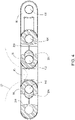
FIG. 2 is a perspective view of a chain conveyor unit. -
FIG. 3 is an exploded view of the chain conveyor unit ofFIG. 2 . -
FIG. 4 is a section view of the chain conveyor unit ofFIG. 2 , viewed along section 4--4. -
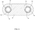
FIG. 5 is a section view of a side link, viewed along section 5--5 ofFIG. 2 . -
FIG. 5A is a section view of a chain conveyor unit ofFIG. 2 , viewed alongsection 5A--5A. -
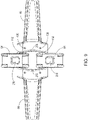
FIG. 6 is a section view of the chain conveyor unit ofFIG. 2 , viewed alongsection 6--6. -
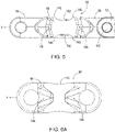
FIG. 6A is a section view of a flight according to another embodiment, viewed along a similar section as 6--6. -
FIG. 7 is a perspective view of a connecting link. -
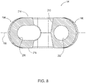
FIG. 8 is a section view of the connecting link ofFIG. 3 , viewed alongsection 8--8. -
FIG. 9 is a plan view of the chain conveyor unit ofFIG. 2 . -
FIG. 10 is a section view of a chain conveyor unit with a connecting link oriented at an angle relative to the flights. - Before any independent embodiments of the disclosure is explained in detail, it is to be understood that the disclosure is not limited in its application to the details of the construction and the arrangements of components set forth in the following description or illustrated in the drawings. The disclosure is capable of other independent embodiments and of being practiced or being carried out in various ways.
- Also, it is to be understood that the phraseology and terminology used herein is for the purpose of description and should not be regarded as limiting. The use of "including," "comprising" or "having" and variations thereof herein is meant to encompass the items listed thereafter and equivalents thereof as well as additional items. The terms "mounted," "connected" and "coupled" are used broadly and encompass both direct and indirect mounting, connecting and coupling.
-
FIG. 1 illustrates amining machine 10, such as a continuous mining machine. In the illustrated embodiment, themining machine 10 includes a frame orchassis 18, aboom 22 pivotably coupled to thechassis 18, and acutter head 26 supported on theboom 22. Thechassis 18 may be supported for movement relative to a support surface (not shown) by a traction mechanism (e.g., crawlers 30). - As shown in
FIG. 1 , a collecting mechanism or gatheringhead 34 is positioned adjacent a first end orforward end 38 of thechassis 18, and aconveyor 42 extends in a continuous loop from theforward end 38 of thechassis 18 toward a second orrear end 46 of thechassis 18. Thegathering head 34 is positioned below thecutter head 26 and includes adeck 50 and a device (e.g., rotating arms 54) that directs dislodged material onto theconveyor 42. Theconveyor 42 transports the cut material along a direction of travel A from theforward end 38 toward therear end 46 of thechassis 18, from the area below thecutter head 26 to another conveyor or a haulage machine (not shown) positioned proximate therear end 46 of thechassis 18. - The
conveyor 42 is a chain conveyor formed by chain link connected sequentially in a continuous loop. Theconveyor 42 drives cut material along a chain pan or deck. Theconveyor 42 is driven by a drive assembly. In some embodiments, the drive assembly includes a shaft oriented laterally relative to thechassis 18 and is driven (e.g., by one or more motors) to rotate relative to thechassis 18, and a sprocket 62 (FIG. 1 ) is coupled to the shaft and drives theconveyor 42 due to rotation of the shaft. -
FIG. 2 shows a unit of achain 82 that forms theconveyor 42. In the illustrated embodiment, thechain 82 includes a pair offlight links 86, a pair ofside links 90, and a coupler link or connectinglink 94 coupling theflight links 86 to theside links 90, and flights orflight bars 98 positioned laterally outward from theflight link 86. Eachflight link 86 is coupled to the adjacent connectinglinks 94 byflight pins 102, and eachside link 90 is coupled to the adjacent connectinglinks 94 bypins 106. Agap 108 is formed between adjacent connectinglinks 94, and the teeth of thesprocket 62 pass into thegap 108 between the connectinglinks 94 to engage and drive theconveyor chain 82. - In the illustrated embodiment, the
conveyor chain 82 includes a sequence of alternating flight links and connecting links, each joined to one another by swivel links. In other embodiments, thechain 82 may include a different sequence of links - for example, multiple connecting links may be positioned between one flight link and the subsequent flight link. Various permutations of the link sequence are possible. Also, in the illustrated embodiment, the spacing between eachflight pin 102 and an adjacent connectingpin 106 is different from the spacing between eachflight pin 102 and anadjacent flight pin 102. - As shown in
FIGS. 2-4 , theflight pins 102 extend through the connectinglink 94 and each end of theflight pins 102 is received within an end portion of one of theflights 86. Similarly, the connectingpins 106 extend through the connectinglink 94 and each end of the connectingpins 106 is received within one of theside links 90. Each of the flight pins 102 and the connectingpins 106 includes aperipheral groove pins 106. - As shown in
FIG. 5 , when the ends of the connectingpins 106 are positioned within openings in the side links 90, eachperipheral groove 124 of the connectingpins 106 is aligned with ahole 126 extending between the opening in the associatedside link 90 and an outer surface of theside link 90. Thegroove 124 is also aligned within acomplementary groove 128 extending at least partially along the perimeter of the opening. A retainer (e.g., an elongated wire, not shown) can be inserted into thehole 126 to wrap around theperipheral groove 124, thereby engaging thegroove 124 and thegroove 128 to retain the connectingpin 126. In some embodiments, the retainer may be formed from a polymeric material (e.g., plastic, nylon) that can be broken by an operator to facilitate removal of thepins 106 for replacement/servicing. - Each
flight 86 includes aninner surface 208 including a pair ofopenings 134, each of which receives an end of one of the flight pins 102. As shown inFIG. 5A , each of theopenings 134 is formed as a blind hole, and the end of the flight pins 102 are enclosed within theflight 86. Similar to the engagement between the side links 90 and the connectingpins 106, when the ends of the flight pins 102 are positioned within theopenings 134 of theflights 86, eachperipheral groove 122 of the flight pins 102 is aligned with ahole 130 and agroove 138 extending around an inner surface of theopening 134. It is understood that the flight pins 102 and the end portions of theflights 86 are coupled in a similar manner to the connectingpins 106 and side links 90. In some embodiments, the retainer may be formed from a polymeric material (e.g., plastic, nylon) that can be broken by an operator to facilitate removal of thepins 102 for replacement/servicing. - As shown in
FIGS. 2 and6 , eachflight 86 includes arecess 142 extending substantially along the length of theflight bar 98. In some embodiments, therecess 142 extends along only a portion of the length of theflight bar 98. As shown inFIG. 6 , therecess 142 may have an arcuate (e.g., elliptical) profile relative to a transverse section of theflight 86, and therecess 142 tapers such that therecess 142 becomes narrower toward the distal end of theflight 86. In addition, theflight 86 includes twoedges 146 on each side of therecess 142, and theedges 146 provide multiple engagement regions for scraping material along the conveyor deck. Also, in other embodiments therecess 142 may have a differently shaped profile (e.g., rectangular shaped, V-shaped, etc.). - In addition, rather than being planar, the
sides 148 of theflight bar 98 protrude outwardly at a middle section and taper inwardly toward the upper and lower surfaces. Stated another way, the side surfaces 148 of theflight bar 98 are convex such that theflight bar 98 is widest near a center portion. In other embodiments, as shown inFIG. 6A , the side surfaces 148 of theflight bar 98 are concave such that theflight bar 98 is narrowest near a center portion. The concave shape provides an X-shaped profile, which may require less material and be lighter while still maintaining sufficient strength. In some embodiments, theflight bar 98 is symmetric about a plane encompassing the direction of travel A (e.g., about a horizontal plane). - As shown in
FIGS. 7 and8 , the connectinglink 94 includes afirst end 190 and asecond end 194, and alink axis 198 extended between thefirst end 190 and thesecond end 194. Thelink 94 includes shoulders orridges 200 that protrude from the portions adjacent theends first opening 202 and asecond opening 206 extend laterally from one side of the connectinglink 94 to another opposite side of the connectinglink 94. In the illustrated embodiment, thefirst opening 202 has a substantially circular profile, while thesecond opening 206 has an oblong or oval profile. The oblong profile of thesecond opening 206 permits pivoting movement of the connectinglink 94 relative to the flight pins 102 (FIG. 4 ). As shown inFIGS. 9 and10 , theinner surface 208 of the flight links 86 may have an arcuate or concave profile to facilitate pivoting movement of the connectinglink 94. - The connecting
link 94 has an increased outer wall thickness compared to conventional links, thereby providing greater strength and durability. In addition, the connectinglink 94 has a unitary or single-piece construction to reduce the number of parts and reduce wear. - In addition, the connecting
link 94 includes arelief opening 210 extending between one side of thelink 94 to the other side. In the illustrated embodiment, therelief opening 210 extends through the connectinglink 94 from anupper surface 214 to a lower surface 218 (e.g., in a substantially vertical direction). Therelief opening 210 may be tapered outwardly from a center of thelink 94 in each direction, toward theupper surface 214 and thelower surface 218. In addition, therelief opening 210 at least partially intersects thesecond opening 206, such that thesecond opening 206 provides communication with therelief opening 210. During operation of the conveyor, particulate material (e.g., dirt) may accumulate in thesecond opening 206. Therelief opening 210 permits removal or evacuation of the particulate material from thesecond opening 206. - Although the conveyor is described above with respect to a continuous mining machine, it is understood that the conveyor may be incorporated into other types of machines including but not limited to roadheaders and entry drivers, as well as loading and hauling machines including but not limited to shuttle cars, battery haulers, or other types.
- Although aspects have been described in detail with reference to certain preferred embodiments, variations and modifications exist within the scope and spirit of one or more independent aspects as described.
- The invention is not restricted to the details of the foregoing embodiment(s). The invention extends to any novel one, or any novel combination, of the features disclosed in this specification (including any accompanying claims, abstract and drawings), or to any novel one, or any novel combination, of the steps of any method or process so disclosed.
- Attention is directed to all papers and documents which are filed concurrently with or previous to this specification in connection with this application and which are open to public inspection with this specification, and the contents of all such papers and documents are incorporated herein by reference.
- All of the features disclosed in this specification (including any accompanying claims, abstract and drawings), and/or all of the steps of any method or process so disclosed, may be combined in any combination, except combinations where at least some of such features and/or steps are mutually exclusive.
- Each feature disclosed in this specification (including any accompanying claims, abstract and drawings) may be replaced by alternative features serving the same, equivalent or similar purpose unless expressly stated otherwise. Thus, unless expressly stated otherwise, each feature disclosed is one example only of a generic series of equivalent or similar features.
Claims (20)
- A link for a conveyor chain, the link comprising:a link body including a first end and a second end opposite the first end;a first opening proximate the first end and extending in a direction transverse to a direction of travel of the link, the first opening configured to receive a first connecting member;a second opening proximate the second end and extending in a direction transverse to the direction of travel of the link, the second opening configured to receive a second connecting member; anda relief opening extending through the link body and positioned between the first end and the second end.
- The link of claim 1, wherein at least one of the first opening and the second opening has an oblong profile.
- The link of claim 1 or claim 2, wherein the relief opening is perpendicular to a direction of travel of the link, and wherein the relief opening is perpendicular to the first opening.
- The link of any preceding claim wherein the at least one relief opening tapers outwardly from a center of the link.
- The link of any preceding claim, wherein the link body includes a center plane extending through the first end and the second end, wherein a surface of the relief opening tapers inwardly from an upper surface of the link body and a surface of the relief opening tapers inwardly from a lower surface of the link body.
- The link of any preceding claim, wherein the relief opening at least partially intersects the second opening.
- The link of claim 6, wherein the second opening has an oblong profile that is elongated in a direction parallel to the direction of travel, and wherein the relief opening intersects a portion of the second opening.
- A link for a conveyor chain, the link comprising:a body having an inner surface, the inner surface including at least one opening therein, the at least one opening configured to receive a coupling pin; anda flight bar extending laterally from the body opposite the inner surface, the flight bar including a leading side and a trailing side, a lower surface of the flight bar including a first edge proximate the leading side and a second edge proximate the trailing side, the flight bar further including a recess disposed between the first edge and the second edge and extending at least partially along a length of the flight bar.
- The link of claim 8, wherein the recess has an arcuate profile relative to a transverse section of the flight bar.
- The link of claim 8 or claim 9, wherein a side of the flight bar adjacent the recess is convex
- The link of any one of claims 8 to 10, wherein the flight bar is symmetric about a plane containing a direction of travel of the link.
- The link of any one of claims 8 to 11, wherein the flight bar has an X-shaped profile when viewed along a longitudinal extent of the flight bar
- The link of any one of claims 8 to 12, wherein the inner surface of the body is arcuate.
- The link of any one of claims 8 to 13, wherein the opening is a blind hole configured to receive a pin.
- The link of any one of claims 8 to 14, wherein the recess tapers toward a distal end of the flight bar.
- A conveyor chain comprising:a first flight link including an arcuate inner surface facing a centerline of the conveyor chain and a flight bar extending laterally away from the centerline of the conveyor chain, the flight bar including a recess defining two edges configured to scrape material along a conveyor deck;a second flight link disposed laterally opposite the first flight link, the second flight link including an arcuate inner surface facing the centerline of the conveyor chain and a flight bar extending laterally away from the centerline of the conveyor chain in a direction opposite the flight bar of the first flight link, the flight bar including a recess defining two edges configured to scrape material along the conveyor deck;a connecting link positioned between the first flight link and the second flight link, the connecting link including a relief opening extending therethrough; andat least one pin coupling the first flight link, the connecting link, and the second flight link.
- The conveyor chain of claim 16, wherein the at least one pin pivotally couples the connecting link to the first flight link and the second flight link, the connecting link configured to pivot within a plane containing a longitudinal axis of the at least one pin and the centerline of the conveyor chain.
- The conveyor chain of claim 16 or claim 17, further comprising a retainer configured to secure the first flight link and the second flight link to the pin.
- The conveyor chain of any one of claims 16 to 18 wherein the retainer is formed of a polymeric material.
- The conveyor chain of any one of claims 16 to 19, wherein the retainer is a wire.
Applications Claiming Priority (2)
| Application Number | Priority Date | Filing Date | Title |
|---|---|---|---|
| US202163142989P | 2021-01-28 | 2021-01-28 | |
| US202163159652P | 2021-03-11 | 2021-03-11 |
Publications (2)
| Publication Number | Publication Date |
|---|---|
| EP4046944A2 true EP4046944A2 (en) | 2022-08-24 |
| EP4046944A3 EP4046944A3 (en) | 2022-11-16 |
Family
ID=80121978
Family Applications (1)
| Application Number | Title | Priority Date | Filing Date |
|---|---|---|---|
| EP22153906.7A Pending EP4046944A3 (en) | 2021-01-28 | 2022-01-28 | Chain conveyor and link for same |
Country Status (6)
| Country | Link |
|---|---|
| US (1) | US11858745B2 (en) |
| EP (1) | EP4046944A3 (en) |
| CN (2) | CN217731634U (en) |
| AU (1) | AU2022200568A1 (en) |
| CA (1) | CA3146838A1 (en) |
| ZA (1) | ZA202201354B (en) |
Cited By (1)
| Publication number | Priority date | Publication date | Assignee | Title |
|---|---|---|---|---|
| PL443313A1 (en) * | 2022-12-27 | 2024-07-01 | Politechnika Śląska | Removable pull chain, especially for mining machines |
Families Citing this family (1)
| Publication number | Priority date | Publication date | Assignee | Title |
|---|---|---|---|---|
| CN115715148A (en) * | 2021-06-22 | 2023-02-24 | 株式会社海泰 | Feed supply trough structure and feed supply auxiliary |
Family Cites Families (146)
| Publication number | Priority date | Publication date | Assignee | Title |
|---|---|---|---|---|
| US231186A (en) | 1880-08-17 | Log-conveyer | ||
| US572991A (en) | 1896-12-15 | Chain | ||
| US708924A (en) | 1902-04-18 | 1902-09-09 | John G Scott | Conveyer-chain. |
| US1020863A (en) | 1908-11-05 | 1912-03-19 | Wenzel Weichseldorfer | Conveyer-cleat. |
| US1008890A (en) | 1911-08-07 | 1911-11-14 | Ernest Demarest | Cable-chain conveyer-cleat. |
| US1153375A (en) | 1913-12-17 | 1915-09-14 | Alonzo E Elliott | Conveyer-bucket. |
| US1427229A (en) | 1922-01-30 | 1922-08-29 | Ross Meehan Foundries | Conveyer cleat |
| GB205440A (en) | 1923-04-16 | 1923-10-18 | George Carstens | Improvements in drive chain for conveyers |
| US1699334A (en) | 1926-09-07 | 1929-01-15 | Link Belt Co | Scraper attachment for chain belts |
| US1869050A (en) | 1932-04-06 | 1932-07-26 | William R Coppage | Conveyer chain |
| US2222025A (en) | 1939-02-08 | 1940-11-19 | Charles E Kimball | Chain |
| US2386619A (en) | 1944-03-27 | 1945-10-09 | Long Super Mine Car Company | Tail section for chain conveyers |
| US2450501A (en) | 1945-04-04 | 1948-10-05 | John L Clarkson | Conveyer chain |
| GB658623A (en) | 1948-08-13 | 1951-10-10 | John Leroy Clarkson | Conveyor chains |
| GB671424A (en) | 1949-08-23 | 1952-05-07 | Henry Waldemar Hapman | Improvements relating to endless driving and conveyor chains |
| US2674365A (en) | 1951-09-12 | 1954-04-06 | Joy Mfg Co | Flight conveyer chain |
| US2754957A (en) | 1953-06-11 | 1956-07-17 | Electric Steel Foundry | Conveyor flight |
| US2784836A (en) | 1954-04-05 | 1957-03-12 | Tourneau Robert G Le | Self-cleaning chains and supporting sprockets |
| US2761548A (en) | 1955-06-24 | 1956-09-04 | Long Company | Scraper flight and built-up conveyor chain and flight combination |
| US3005358A (en) | 1960-05-16 | 1961-10-24 | United Shoe Machinery Corp | Irreversible high efficiency transmission |
| US3089579A (en) | 1960-06-08 | 1963-05-14 | Goodman Mfg Co | Composite flight |
| US3145576A (en) | 1960-06-14 | 1964-08-25 | Austin Hoy & Co Ltd | Universal joint for chain links |
| US3103275A (en) | 1960-06-17 | 1963-09-10 | Joy Mfg Co | Conveyor device |
| US3119276A (en) | 1961-11-13 | 1964-01-28 | Chain Belt Co | Block link with integral bushing |
| US3452228A (en) | 1962-10-15 | 1969-06-24 | Scott & Fetzer Co | Motor construction |
| US3225897A (en) | 1962-10-17 | 1965-12-28 | Lester G Rollins | Conveyor device |
| US3324990A (en) | 1966-05-05 | 1967-06-13 | Nat Mine Service Co | Articulated chain type conveyor |
| US3472563A (en) | 1967-11-22 | 1969-10-14 | Outboard Marine Corp | Vehicle track |
| US3540566A (en) | 1967-12-15 | 1970-11-17 | Cincinnati Milacron Inc | Connector system |
| US3602364A (en) | 1969-07-22 | 1971-08-31 | Stevens & Co Inc J P | Segmented belt |
| US4037713A (en) | 1974-03-22 | 1977-07-26 | Gewerkschaft Eisenhutte Westfalia | Scraper-chain conveyors |
| US4218932A (en) | 1977-04-29 | 1980-08-26 | The Gates Rubber Company | Belt sprocket wheel |
| SU713780A1 (en) | 1977-07-01 | 1980-02-05 | Ivashkov Ilya | Scraper conveyer pull member |
| US4238028A (en) | 1977-07-28 | 1980-12-09 | Joy Manufacturing Company | Flight conveyor |
| US4175797A (en) | 1977-10-12 | 1979-11-27 | The Cincinnati Mine Machinery Company | Ground engaging tread or track comprised of improved articulated crawler pads, for treaded vehicles such as mining machines and the like |
| US4202219A (en) | 1978-04-18 | 1980-05-13 | C. L. Frost & Son, Inc. | Chain pin assembly with captive securing means |
| CA1126666A (en) | 1978-12-26 | 1982-06-29 | Andrew H. Bekkala | Caliper guide assembly for disc brakes |
| SU963922A2 (en) | 1980-05-26 | 1982-10-07 | Всесоюзный Научно-Исследовательский И Проектно-Конструкторский Институт Горнорудного Машиностроения | Double-hinge scraper chain |
| DE3151059A1 (en) | 1981-12-23 | 1983-07-28 | Gewerkschaft Eisenhütte Westfalia, 4670 Lünen | Loading conveyor, in particular for winning and heading machines and the like |
| US5096048A (en) | 1982-11-06 | 1992-03-17 | Klockner-Becorit Gmbh | Conveyor |
| US4585117A (en) | 1984-05-24 | 1986-04-29 | Esco Corporation | Flight for link chain conveyor |
| US4766995A (en) | 1986-09-03 | 1988-08-30 | The Cincinnati Mine Machinery Company | Pusher-type conveyor chain |
| US4899868A (en) | 1986-09-04 | 1990-02-13 | The Goodyear Tire & Rubber Company | Conveyor for a crop harvester |
| US4844314A (en) | 1988-02-08 | 1989-07-04 | International Business Machines Corporation | Pulley for forms feed tractor |
| JPH0211250U (en) | 1988-07-05 | 1990-01-24 | ||
| GB8902510D0 (en) | 1989-02-04 | 1989-03-22 | Huwood Ltd | Chain |
| US4964344A (en) | 1989-04-28 | 1990-10-23 | Mid-West Conveyor Company, Inc. | Side link pusher dog with lubrication passage |
| US5177949A (en) | 1989-06-09 | 1993-01-12 | Zinser Textilmaschinen Gmbh | Apparatus for transporting bobbin tubes of a textile machine |
| US5088594A (en) | 1989-06-16 | 1992-02-18 | Joy Technologies Inc. | Chain and flight conveyor |
| US5000310A (en) | 1989-06-16 | 1991-03-19 | Joy Technologies Inc. | Chain and flight conveyor |
| DE4007685A1 (en) | 1990-03-10 | 1991-09-12 | Halbach & Braun Ind Anlagen | CHAIN TAPE FOR CHAIN SCRATCH CONVEYOR |
| JPH0810352Y2 (en) | 1990-04-19 | 1996-03-29 | 日立金属株式会社 | Flight for sludge attractor and its roller shoe |
| US5186526A (en) | 1990-08-31 | 1993-02-16 | General Chemical Corporation | One-piece crawler pad |
| US5165766A (en) | 1991-01-09 | 1992-11-24 | Joy Technologies Inc. | Tram chain connection link |
| DE4115810A1 (en) | 1991-05-15 | 1992-11-19 | Westfalia Becorit Ind Tech | DRIVER FOR DOUBLE SLEEVE STRING CHAINS WITH SWIVELING CONNECTED CLAMP |
| US5156256A (en) | 1992-01-07 | 1992-10-20 | Joy Technologies Inc. | Elevated auxiliary conveying apparatus |
| US5305872A (en) | 1992-01-30 | 1994-04-26 | Esco Corporation | Chain |
| US5226526A (en) | 1992-07-16 | 1993-07-13 | O'brien Systems | Detachable flights for bulk material conveyors |
| US5215185A (en) * | 1992-09-08 | 1993-06-01 | Rexnord Corporation | Breakable molded plastic links for forming conveyor chain |
| RU2064393C1 (en) | 1993-01-21 | 1996-07-27 | Виктор Григорьевич Смирнов | Method of disassembling air cleaner |
| DE9300855U1 (en) | 1993-01-22 | 1993-03-11 | Gebhardt Fördertechnik GmbH, 6920 Sinsheim | Kit for standardization and creation of a modular system for chain conveyors, chain accumulation conveyors and/or toothed belt conveyors |
| CN2211981Y (en) | 1994-04-13 | 1995-11-08 | 太原锅炉厂 | Frame transport chain |
| IT233253Y1 (en) | 1994-04-15 | 2000-01-26 | Berco Spa | TRUCK TROLLEY IN PARTICULAR FOR SMALL EXCAVATORS |
| US5628393A (en) | 1995-06-08 | 1997-05-13 | Steeber; Dorian F. | Conveyor apparatus having a nodular conveying surface |
| DE19633298B4 (en) | 1996-08-19 | 2006-10-19 | Bühler AG | conveyor chain |
| US5762424A (en) | 1996-10-03 | 1998-06-09 | Rexnord Corporation | Full perimeter fiber wound bearing construction |
| US5911305A (en) * | 1996-11-22 | 1999-06-15 | Span Tech Corporation | Endless loop modular conveyor system with drive screw |
| AU1018501A (en) | 1998-11-20 | 2001-05-08 | Vkr Holding A/S | A chain joint assembly and a method for the manufacture thereof |
| DE10040186A1 (en) | 2000-08-17 | 2002-03-14 | K B P Kettenwerk Becker Prunte | Carrier for scraper chain conveyor has top and bottom parts, chain beds, cavities for screws, guide surfaces, and side guide sections. |
| AU2001296806A1 (en) | 2000-10-06 | 2002-04-15 | Randall Lee Morris | Conveyor chain for mining machinery |
| US6447397B1 (en) | 2000-10-13 | 2002-09-10 | Weasler Engineering, Inc. | Detent torque overload clutch |
| JP4514305B2 (en) | 2000-10-17 | 2010-07-28 | 株式会社椿本チエイン | Low noise type offset chain |
| GB0106190D0 (en) | 2001-03-14 | 2001-05-02 | Pennine Ind Equipment Ltd | Enclosure member |
| US7217510B2 (en) | 2001-06-26 | 2007-05-15 | Isis Pharmaceuticals, Inc. | Methods for providing bacterial bioagent characterizing information |
| US20050274590A1 (en) | 2001-08-03 | 2005-12-15 | C. U. E., Inc. | Flight for a conveyor |
| US7246699B2 (en) | 2002-03-08 | 2007-07-24 | Frost Links, Inc. | Conveyor chain |
| DE20206947U1 (en) | 2002-05-02 | 2003-02-06 | Joh. Winklhofer & Söhne GmbH und Co KG, 81369 München | Link chain with nitrided link pin |
| US6662932B1 (en) | 2003-06-01 | 2003-12-16 | Joy Mm Delaware, Inc. | Chain and flight conveyor with swivel links |
| DE20300239U1 (en) | 2003-01-07 | 2003-03-13 | DBT GmbH, 44534 Lünen | Scraper is for chain scraper conveyor, particularly of the mining double central chain type, comprises a stirrup part engaging beneath at least one horizontal chain member and scraper part which encloses partly the stirrup part |
| US7118648B2 (en) | 2003-01-08 | 2006-10-10 | Sdf Group, Llc | Paper Strap |
| DE20310521U1 (en) * | 2003-07-03 | 2004-11-04 | Rud-Kettenfabrik Rieger & Dietz Gmbh U. Co. | Conveyor chain esp. for use with bucket chain conveyors has inner links of steel/cast steel with cross bars having projecting wear zones facing and away from drive pulleys |
| US7036657B1 (en) | 2004-02-17 | 2006-05-02 | Robinson Christopher J | Conveyor chain |
| US7794329B2 (en) | 2004-05-03 | 2010-09-14 | Weasler Engineering, Inc. | Torque overload clutch |
| US20060058144A1 (en) | 2004-07-07 | 2006-03-16 | Mario Lacerda | System for lubricating a rivetless chain |
| JP4357402B2 (en) | 2004-10-18 | 2009-11-04 | 株式会社椿本チエイン | Transport device |
| US7343730B2 (en) | 2004-10-28 | 2008-03-18 | Humcke Michael W | Investment cast, stainless steel chain link and casting process therefor |
| ES2245259B1 (en) | 2005-02-02 | 2007-02-16 | Afher Eurobelt, S.A. | DRIVE CROWN FOR CONVEYOR CHAINS. |
| DE102006030984B4 (en) | 2005-08-17 | 2016-08-04 | Caterpillar Global Mining Europe Gmbh | Kettenantriebs- or deflection and thereby used chain belt |
| US20070108025A1 (en) | 2005-11-17 | 2007-05-17 | Jean-Marc Boudreau | Slides for endless belt conveyors |
| US7438180B1 (en) | 2005-12-09 | 2008-10-21 | Taylor John S | Multi-axis adjustable conveyor |
| US7364036B2 (en) * | 2006-02-09 | 2008-04-29 | Habasit Ag | Module for a perforated flat top belt with hinge gap for better fluid flow |
| US7422256B2 (en) | 2006-03-03 | 2008-09-09 | Mueller Dewayne | Lifting sling with excessive elongation warning indicator |
| DE502006007000D1 (en) | 2006-03-24 | 2010-07-01 | Bucyrus Europe Gmbh | CONCRETE CHAIN FOR CHAIN CONVEYOR AND CHAIN WHEEL FOR THIS |
| JP2009532308A (en) | 2006-04-03 | 2009-09-10 | スパン テック エルエルシー | Product conveying component with powder coating and method related thereto |
| AU2007286864A1 (en) | 2006-08-24 | 2008-02-28 | Frost Links, Inc. | Chain wear monitoring device |
| US20080284245A1 (en) | 2007-05-18 | 2008-11-20 | Caterpillar Inc. | Machine track system and machine track segment |
| CN201087012Y (en) | 2007-08-10 | 2008-07-16 | 三一重型装备有限公司 | Support scratch board used for conveying equipment on coal mine working surface |
| US7624858B2 (en) * | 2007-12-21 | 2009-12-01 | Habasit Ag | Modular plastic conveyor belt for spiral conversion |
| US9415939B2 (en) | 2008-04-03 | 2016-08-16 | Joy Mm Delaware, Inc. | Chain and flight conveyor |
| US8950571B2 (en) | 2008-04-03 | 2015-02-10 | Joy Mm Delaware, Inc. | Chain and flight conveyor |
| US8177049B2 (en) | 2008-04-03 | 2012-05-15 | Joy Mm Delaware, Inc. | Chain and flight conveyor |
| NZ567552A (en) | 2008-04-18 | 2011-03-31 | Southchain Conveying Systems N Z Ltd | Chain link and chain |
| EP2136095B1 (en) | 2008-06-20 | 2011-08-17 | GKN Walterscheid GmbH | Coupling for limiting rotational movement |
| AT507167B1 (en) | 2008-07-25 | 2010-08-15 | Pewag Austria Gmbh | MITNEHMER |
| US9227787B2 (en) | 2008-09-22 | 2016-01-05 | The Cincinnati Mine Machinery Company | Conveyor chain |
| US10875717B2 (en) | 2008-09-22 | 2020-12-29 | The Cincinnati Mine Machinery Company | Conveyor chain |
| US9487358B2 (en) | 2008-09-22 | 2016-11-08 | The Cincinnati Mine Machinery Company | Conveyor chain |
| US8453826B2 (en) | 2008-09-22 | 2013-06-04 | The Cincinnati Mine Machinery Company | Conveyor chain |
| US8936146B2 (en) | 2008-09-22 | 2015-01-20 | The Cincinnati Mine Machinery Company | Conveyor chain |
| WO2010058627A1 (en) | 2008-11-18 | 2010-05-27 | 横浜ゴム株式会社 | Pneumatic tire |
| DE202009000265U1 (en) | 2009-01-07 | 2010-05-12 | Bucyrus Europe Gmbh | Link chain for chain conveyors and horizontal chain links for this purpose |
| US8978877B2 (en) | 2009-04-30 | 2015-03-17 | Joy Mm Delaware, Inc. | Sound dampening conveyor chain flight |
| US8141696B2 (en) | 2009-04-30 | 2012-03-27 | Joy Mm Delaware, Inc. | Replaceable sound dampening conveyor chain flight |
| CN101602433B (en) | 2009-07-01 | 2011-10-12 | 宣化冶金工业有限责任公司 | Scraper of CuNiMo alloying isothermal quenching ductile iron scraper conveyor and preparation method |
| AT508498B1 (en) | 2009-07-09 | 2011-09-15 | Sandvik Mining & Constr Oy | RAILWAY TRUCK FOR MINING MACHINES, AS WELL AS CHAIN MEMBER FOR A TRACKING DEVICE AND METHOD FOR THE PRODUCTION THEREOF |
| US8074438B2 (en) | 2009-10-19 | 2011-12-13 | Joy Mm Delaware, Inc. | Link chain |
| EP2390530B1 (en) | 2010-05-31 | 2012-03-28 | iwis motorsysteme GmbH & Co. KG | Articulated chain with chain links made of boron manganese steel |
| US8672110B2 (en) | 2010-09-29 | 2014-03-18 | Actuant Corporation | Automatic torque overload clutch |
| CH704136A1 (en) | 2010-11-26 | 2012-05-31 | Ferag Ag | Funding chain for funding for a conveyor. |
| JP5576263B2 (en) | 2010-12-28 | 2014-08-20 | 保線機器整備株式会社 | Roadbed ballast scraping chain |
| US8905493B2 (en) | 2011-05-11 | 2014-12-09 | Caterpillar Inc. | Track link with replaceable rail and method of replacing worn rails on track links |
| US8850754B2 (en) | 2011-10-17 | 2014-10-07 | Dynoraxx, Inc. | Molded solar panel racking assembly |
| SE536767C2 (en) | 2012-03-20 | 2014-07-22 | Flexlink Components Ab | Transport chain link, transport chain and drive wheels for a transport chain |
| ZA201303709B (en) | 2012-05-25 | 2014-04-30 | Joy Mm Delaware Inc | Crawler track |
| DE202012102111U1 (en) | 2012-06-08 | 2013-09-09 | Caterpillar Global Mining Europe Gmbh | Scratch for chain scraper conveyor, scraper bridge and bracket for this purpose |
| US8899409B2 (en) | 2012-06-13 | 2014-12-02 | Ashworth Bros., Inc. | Conveyor belt link having wear resistant portion |
| US8887901B2 (en) | 2012-07-30 | 2014-11-18 | Joy Mm Delaware, Inc. | Conveyor sprocket assembly |
| CA2888898A1 (en) | 2012-10-25 | 2014-05-01 | Solus Industrial Innovations, Llc | Device and method for controlling the wear of the rail of a conveyor |
| US20140131177A1 (en) | 2012-11-15 | 2014-05-15 | Habasit Ag | Dampened Radius Modular Conveyor Belts and Belt Modules |
| US8960809B2 (en) | 2013-02-25 | 2015-02-24 | Joy Mm Delaware, Inc. | Continuous miner mid-conveyor drive |
| CA2914482C (en) | 2013-06-03 | 2022-08-30 | The Cincinnati Mine Machinery Company | Conveyor chain |
| US20160200520A1 (en) | 2013-08-27 | 2016-07-14 | Rexnord Flattop Europe B.V. | Conveyor module, conveyor mat or chain, method for monitoring wear of a conveyor element, and conveyor system |
| JP5946222B2 (en) * | 2013-11-28 | 2016-07-05 | 株式会社椿本チエイン | Metal chain |
| NL2012090C2 (en) | 2014-01-15 | 2015-07-16 | Rexnord Flattop Europe Bv | MODULAR TRANSPORT MAT AND MODULE THEREFOR, AND CHAIN WHEEL AND TRANSPORT SYSTEM. |
| US9434428B2 (en) | 2014-06-06 | 2016-09-06 | Caterpillar Inc. | Track pad wear indicator |
| CN105221664A (en) | 2014-06-25 | 2016-01-06 | 天津市强力链条有限公司 | A kind of readily removable chain |
| CN104295668A (en) | 2014-10-09 | 2015-01-21 | 江苏永钢集团有限公司 | Transmission chain connecting device |
| US9643668B2 (en) | 2014-12-05 | 2017-05-09 | Caterpillar Global Mining America Llc | Sprocket for a track-type machine |
| WO2016138010A1 (en) * | 2015-02-23 | 2016-09-01 | Span Tech Llc | Modular link conveyor with features for enhancing the efficient conveyance of articles |
| US20150266527A1 (en) | 2015-06-09 | 2015-09-24 | Caterpillar Inc. | Link for track assembly |
| CN105083860A (en) | 2015-08-10 | 2015-11-25 | 浙江神龙链传动有限公司 | Driving chain for material conveying device |
| CN204916962U (en) | 2015-09-08 | 2015-12-30 | 浙江德马工业设备有限公司 | Location and transmission structure suitable for roller sprocket |
| CN105386759B (en) | 2015-10-21 | 2018-03-20 | 三门峡义翔铝业有限公司 | A kind of double drum type coal mine development machine |
| WO2017139748A1 (en) * | 2016-02-12 | 2017-08-17 | Span Tech Llc | Modular link conveyor with features for enhancing efficient article conveyance |
| CN110709219B (en) | 2017-03-06 | 2022-04-29 | 久益环球地下采矿有限责任公司 | Chain conveyor and coupling chain link for chain conveyor |
| US10556748B1 (en) * | 2018-08-09 | 2020-02-11 | T.F. & J.H. Braime (Holdings) P.L.C. | Round bottom drag conveyor paddle assembly and method of making the same |
-
2022
- 2022-01-27 CA CA3146838A patent/CA3146838A1/en active Pending
- 2022-01-28 CN CN202220238373.2U patent/CN217731634U/en active Active
- 2022-01-28 EP EP22153906.7A patent/EP4046944A3/en active Pending
- 2022-01-28 US US17/587,328 patent/US11858745B2/en active Active
- 2022-01-28 CN CN202210107279.8A patent/CN114803313A/en active Pending
- 2022-01-28 AU AU2022200568A patent/AU2022200568A1/en active Pending
- 2022-01-28 ZA ZA2022/01354A patent/ZA202201354B/en unknown
Cited By (1)
| Publication number | Priority date | Publication date | Assignee | Title |
|---|---|---|---|---|
| PL443313A1 (en) * | 2022-12-27 | 2024-07-01 | Politechnika Śląska | Removable pull chain, especially for mining machines |
Also Published As
| Publication number | Publication date |
|---|---|
| CA3146838A1 (en) | 2022-07-28 |
| CN114803313A (en) | 2022-07-29 |
| US11858745B2 (en) | 2024-01-02 |
| CN217731634U (en) | 2022-11-04 |
| ZA202201354B (en) | 2022-08-31 |
| AU2022200568A1 (en) | 2022-08-11 |
| US20220234835A1 (en) | 2022-07-28 |
| EP4046944A3 (en) | 2022-11-16 |
Similar Documents
| Publication | Publication Date | Title |
|---|---|---|
| US11530095B2 (en) | Chain conveyor and link for same | |
| EP4046944A2 (en) | Chain conveyor and link for same |
Legal Events
| Date | Code | Title | Description |
|---|---|---|---|
| PUAI | Public reference made under article 153(3) epc to a published international application that has entered the european phase |
Free format text: ORIGINAL CODE: 0009012 |
|
| STAA | Information on the status of an ep patent application or granted ep patent |
Free format text: STATUS: THE APPLICATION HAS BEEN PUBLISHED |
|
| AK | Designated contracting states |
Kind code of ref document: A2 Designated state(s): AL AT BE BG CH CY CZ DE DK EE ES FI FR GB GR HR HU IE IS IT LI LT LU LV MC MK MT NL NO PL PT RO RS SE SI SK SM TR |
|
| PUAL | Search report despatched |
Free format text: ORIGINAL CODE: 0009013 |
|
| AK | Designated contracting states |
Kind code of ref document: A3 Designated state(s): AL AT BE BG CH CY CZ DE DK EE ES FI FR GB GR HR HU IE IS IT LI LT LU LV MC MK MT NL NO PL PT RO RS SE SI SK SM TR |
|
| RIC1 | Information provided on ipc code assigned before grant |
Ipc: F16G 13/12 20060101ALI20221010BHEP Ipc: F16G 15/12 20060101ALI20221010BHEP Ipc: F16G 13/18 20060101ALI20221010BHEP Ipc: F16G 13/06 20060101ALI20221010BHEP Ipc: B65G 19/22 20060101ALI20221010BHEP Ipc: B65G 19/24 20060101ALI20221010BHEP Ipc: B65G 19/20 20060101ALI20221010BHEP Ipc: B65G 19/08 20060101AFI20221010BHEP |
|
| STAA | Information on the status of an ep patent application or granted ep patent |
Free format text: STATUS: REQUEST FOR EXAMINATION WAS MADE |
|
| 17P | Request for examination filed |
Effective date: 20230331 |
|
| RBV | Designated contracting states (corrected) |
Designated state(s): AL AT BE BG CH CY CZ DE DK EE ES FI FR GB GR HR HU IE IS IT LI LT LU LV MC MK MT NL NO PL PT RO RS SE SI SK SM TR |
|
| STAA | Information on the status of an ep patent application or granted ep patent |
Free format text: STATUS: EXAMINATION IS IN PROGRESS |