EP4046865A1 - Kopfstützenverriegelung mit formgedächtnislegierungsauslösevorrichtung - Google Patents
Kopfstützenverriegelung mit formgedächtnislegierungsauslösevorrichtung Download PDFInfo
- Publication number
- EP4046865A1 EP4046865A1 EP22157110.2A EP22157110A EP4046865A1 EP 4046865 A1 EP4046865 A1 EP 4046865A1 EP 22157110 A EP22157110 A EP 22157110A EP 4046865 A1 EP4046865 A1 EP 4046865A1
- Authority
- EP
- European Patent Office
- Prior art keywords
- release
- headrest assembly
- vehicle headrest
- latch mechanism
- slide
- Prior art date
- Legal status (The legal status is an assumption and is not a legal conclusion. Google has not performed a legal analysis and makes no representation as to the accuracy of the status listed.)
- Withdrawn
Links
Images


Classifications
-
- B—PERFORMING OPERATIONS; TRANSPORTING
- B60—VEHICLES IN GENERAL
- B60N—SEATS SPECIALLY ADAPTED FOR VEHICLES; VEHICLE PASSENGER ACCOMMODATION NOT OTHERWISE PROVIDED FOR
- B60N2/00—Seats specially adapted for vehicles; Arrangement or mounting of seats in vehicles
- B60N2/80—Head-rests
- B60N2/806—Head-rests movable or adjustable
- B60N2/809—Head-rests movable or adjustable vertically slidable
- B60N2/812—Head-rests movable or adjustable vertically slidable characterised by their locking devices
- B60N2/815—Release mechanisms, e.g. buttons
-
- B—PERFORMING OPERATIONS; TRANSPORTING
- B60—VEHICLES IN GENERAL
- B60N—SEATS SPECIALLY ADAPTED FOR VEHICLES; VEHICLE PASSENGER ACCOMMODATION NOT OTHERWISE PROVIDED FOR
- B60N2/00—Seats specially adapted for vehicles; Arrangement or mounting of seats in vehicles
- B60N2/80—Head-rests
- B60N2/806—Head-rests movable or adjustable
- B60N2/838—Tiltable
- B60N2/841—Tiltable characterised by their locking devices
- B60N2/844—Release mechanisms, e.g. buttons
-
- B—PERFORMING OPERATIONS; TRANSPORTING
- B60—VEHICLES IN GENERAL
- B60N—SEATS SPECIALLY ADAPTED FOR VEHICLES; VEHICLE PASSENGER ACCOMMODATION NOT OTHERWISE PROVIDED FOR
- B60N2/00—Seats specially adapted for vehicles; Arrangement or mounting of seats in vehicles
- B60N2/80—Head-rests
- B60N2/806—Head-rests movable or adjustable
- B60N2/809—Head-rests movable or adjustable vertically slidable
- B60N2/829—Head-rests movable or adjustable vertically slidable characterised by their adjusting mechanisms, e.g. electric motors
-
- B—PERFORMING OPERATIONS; TRANSPORTING
- B60—VEHICLES IN GENERAL
- B60N—SEATS SPECIALLY ADAPTED FOR VEHICLES; VEHICLE PASSENGER ACCOMMODATION NOT OTHERWISE PROVIDED FOR
- B60N2/00—Seats specially adapted for vehicles; Arrangement or mounting of seats in vehicles
- B60N2/80—Head-rests
- B60N2/806—Head-rests movable or adjustable
- B60N2/838—Tiltable
- B60N2/853—Tiltable characterised by their adjusting mechanisms, e.g. electric motors
-
- B—PERFORMING OPERATIONS; TRANSPORTING
- B60—VEHICLES IN GENERAL
- B60N—SEATS SPECIALLY ADAPTED FOR VEHICLES; VEHICLE PASSENGER ACCOMMODATION NOT OTHERWISE PROVIDED FOR
- B60N2/00—Seats specially adapted for vehicles; Arrangement or mounting of seats in vehicles
- B60N2/80—Head-rests
- B60N2/806—Head-rests movable or adjustable
- B60N2/838—Tiltable
- B60N2/856—Tiltable movable to an inoperative or stowed position
- B60N2/859—Tiltable movable to an inoperative or stowed position specially adapted for rear seats
-
- B—PERFORMING OPERATIONS; TRANSPORTING
- B60—VEHICLES IN GENERAL
- B60N—SEATS SPECIALLY ADAPTED FOR VEHICLES; VEHICLE PASSENGER ACCOMMODATION NOT OTHERWISE PROVIDED FOR
- B60N2/00—Seats specially adapted for vehicles; Arrangement or mounting of seats in vehicles
- B60N2/80—Head-rests
- B60N2/806—Head-rests movable or adjustable
- B60N2/838—Tiltable
- B60N2/862—Tiltable with means for maintaining a desired position when the seat-back is adjusted, e.g. parallelogram mechanisms
-
- B—PERFORMING OPERATIONS; TRANSPORTING
- B60—VEHICLES IN GENERAL
- B60N—SEATS SPECIALLY ADAPTED FOR VEHICLES; VEHICLE PASSENGER ACCOMMODATION NOT OTHERWISE PROVIDED FOR
- B60N2/00—Seats specially adapted for vehicles; Arrangement or mounting of seats in vehicles
- B60N2/80—Head-rests
- B60N2/806—Head-rests movable or adjustable
- B60N2/874—Head-rests movable or adjustable movable to an inoperative or stowed position
- B60N2/876—Head-rests movable or adjustable movable to an inoperative or stowed position specially adapted for rear seats
-
- F—MECHANICAL ENGINEERING; LIGHTING; HEATING; WEAPONS; BLASTING
- F03—MACHINES OR ENGINES FOR LIQUIDS; WIND, SPRING, OR WEIGHT MOTORS; PRODUCING MECHANICAL POWER OR A REACTIVE PROPULSIVE THRUST, NOT OTHERWISE PROVIDED FOR
- F03G—SPRING, WEIGHT, INERTIA OR LIKE MOTORS; MECHANICAL-POWER PRODUCING DEVICES OR MECHANISMS, NOT OTHERWISE PROVIDED FOR OR USING ENERGY SOURCES NOT OTHERWISE PROVIDED FOR
- F03G7/00—Mechanical-power-producing mechanisms, not otherwise provided for or using energy sources not otherwise provided for
- F03G7/06—Mechanical-power-producing mechanisms, not otherwise provided for or using energy sources not otherwise provided for using expansion or contraction of bodies due to heating, cooling, moistening, drying or the like
- F03G7/061—Mechanical-power-producing mechanisms, not otherwise provided for or using energy sources not otherwise provided for using expansion or contraction of bodies due to heating, cooling, moistening, drying or the like characterised by the actuating element
- F03G7/0614—Mechanical-power-producing mechanisms, not otherwise provided for or using energy sources not otherwise provided for using expansion or contraction of bodies due to heating, cooling, moistening, drying or the like characterised by the actuating element using shape memory elements
- F03G7/06143—Wires
-
- F—MECHANICAL ENGINEERING; LIGHTING; HEATING; WEAPONS; BLASTING
- F03—MACHINES OR ENGINES FOR LIQUIDS; WIND, SPRING, OR WEIGHT MOTORS; PRODUCING MECHANICAL POWER OR A REACTIVE PROPULSIVE THRUST, NOT OTHERWISE PROVIDED FOR
- F03G—SPRING, WEIGHT, INERTIA OR LIKE MOTORS; MECHANICAL-POWER PRODUCING DEVICES OR MECHANISMS, NOT OTHERWISE PROVIDED FOR OR USING ENERGY SOURCES NOT OTHERWISE PROVIDED FOR
- F03G7/00—Mechanical-power-producing mechanisms, not otherwise provided for or using energy sources not otherwise provided for
- F03G7/06—Mechanical-power-producing mechanisms, not otherwise provided for or using energy sources not otherwise provided for using expansion or contraction of bodies due to heating, cooling, moistening, drying or the like
- F03G7/064—Mechanical-power-producing mechanisms, not otherwise provided for or using energy sources not otherwise provided for using expansion or contraction of bodies due to heating, cooling, moistening, drying or the like characterised by its use
- F03G7/0641—Motors; Energy harvesting or waste energy recovery
-
- H—ELECTRICITY
- H02—GENERATION; CONVERSION OR DISTRIBUTION OF ELECTRIC POWER
- H02N—ELECTRIC MACHINES NOT OTHERWISE PROVIDED FOR
- H02N10/00—Electric motors using thermal effects
Definitions
- the present invention relates to vehicle headrests and, more particularly, to a latch mechanism with a shape memory alloy release assembly for such headrest.
- headrest An example component of an automobile that has historically been developed with an emphasis on strength and comfort is a headrest.
- Most automobiles include headrests atop an occupant's seat and in a position adjacent the occupant's head. Because headrests are specifically designed to interface with an occupant's head, they must be comfortable both tactilely and positionally. In addition to comfort, headrests must be able to withstand amounts of impact to prevent whiplash to the occupant during a rear end collision, and to a certain extent block foreign objects in the event of a crash or sudden braking situation.
- the headrests may reduce the rear and side visibility of the driver, leading to potential safety issues.
- the upright headrest(s) simply result in obstructed visibility without any benefit, unless the driver takes the time and effort to rotate, lower, or otherwise remove the headrest(s) whenever the rear seats are empty.
- an upwardly extending headrest in the upright position may obstruct the ability to rotate the seatbacks downwardly to form a cargo space with a generally flat surface.
- a vehicle headrest assembly includes a latch mechanism moveable between an engaged position and a release position, the engaged position maintaining a first rotational position of the vehicle headrest assembly, the release position allowing a spring force to bias the vehicle headrest assembly to a second rotational position.
- the vehicle headrest assembly also includes a shape memory alloy (SMA) release assembly operatively coupled to the latch mechanism to selectively move the latch mechanism from the engaged position to the release position.
- the SMA release assembly includes an actuator base including a pair of tracks defining a slot, the actuator base including a plurality of retaining tabs.
- the SMA release assembly also includes a printed circuit board (PCB) retained directly to the actuator base and disposed adjacent the plurality of retaining tabs.
- PCB printed circuit board
- the SMA release assembly further includes a slide disposed within the slot and retained to the actuator base with the pair of tracks.
- the SMA release assembly yet further includes a SMA wire connected to a pair of electrical terminals of the PCB and to the slide, the slide moveable to contact and bias the latch mechanism to the release position upon energization and contraction of the SMA wire.
- a vehicle headrest assembly includes a latch mechanism moveable between an engaged position and a release position, the engaged position maintaining a first rotational position of the vehicle headrest assembly, the release position allowing a spring force to bias the vehicle headrest assembly to a second rotational position.
- the latch mechanism includes a lock plate fixed in a non-rotatable manner to an armature, the lock plate defining a detent slot.
- the latch mechanism also includes a lock pawl having a latch finger, the lock pawl rotatable between the engaged position and the release position, wherein the engaged position is defined by insertion of the latch finger in the detent slot, the release position defined by removal of the latch finger from the detent slot.
- the latch mechanism further includes a release lever.
- the latch mechanism yet further includes a pull rod operatively coupled to, or integrally formed with, the release lever, the pull rod operatively coupled to the lock pawl to move the lock pawl between the engaged position and the release position.
- the vehicle headrest assembly also includes a shape memory alloy (SMA) release assembly operatively coupled to the latch mechanism to selectively move the latch mechanism from the engaged position to the release position.
- SMA shape memory alloy
- a headrest assembly intended for providing comfort and safety to occupants of a vehicle by allowing the headrest assembly to be pivotable in a fore-aft direction.
- the headrest assembly is generally referred to with numeral 10.
- the headrest assembly 10 includes a housing 12 that at least partially encloses several components associated with stabilization and/or adjustment of the headrest assembly 10.
- a cushion and a cover may be provided over the housing 12 for aesthetic purposes and occupant comfort.
- a base portion 14 (which may also be referred to as an "armature") is mountable to a vehicle seat and, more specifically, to a top surface of a vehicle seatback.
- the base portion 14 includes two substantially parallel posts 13 that extend substantially vertically and into the seatback. The two posts 13 are connected by a lateral portion 15 of the base portion 14.
- the embodiments described herein allow pivoting of the headrest assembly 10 in a fore-aft direction 16 along the top surface of the seatback.
- the pivoting and pivotable movement described herein may also be referred to as rotating or tilting of the headrest.
- the extent of the movement of the headrest 10 may vary depending upon the particular application of use. In some arrangements, the headrest 10 is pivotal in the fore-aft direction up to about 180° to bring the headrest 10 into substantially flush contact with the seatback, but in other arrangements the headrest 10 is pivotable in the fore-aft direction to a smaller degree.
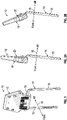
- FIG. 2A is a side view of the headrest assembly 10 in a substantially upright position, wherein the housing 12 is generally aligned in a substantially parallel relationship with the seatback.
- FIG. 2B is a side view of the headrest assembly 10 in a pivoted position, wherein the housing 12 is pivoted until it has a forward tilt with respect to the seatback, e.g., a tilt in the fore direction.
- FIG. 3 is a partially disassembled rear perspective view of the headrest assembly 10.
- the housing 12 includes a front shell 18 which may be operatively coupled to a rear shell (not shown) to define a cavity 20 therebetween.
- the rear shell is removed to illustrate a latch mechanism 30 disposed within the cavity 20.
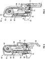
- FIG. 4 is a further disassembled view with the front shell 18 also removed.
- the cavity 20 includes a pair of journal blocks 22 having a lateral passage 23 therethrough to receive the lateral portion 15 of the base portion 14 in rotatable fashion, thus enabling the housing 12 to move angularly between the retracted and deployed positions of FIGS. 2A and 2B .
- a pair of helical coil springs 24 are secured about the lateral portion 15 adjacent to the blocks 22, with one end of each spring 24 secured to the lateral portion 15 and the other end 26 impinging on a portion of the interior the housing 12.
- the springs 24 deliver a resilient restoring force that urges the housing 12 to rotate toward the second position of FIG. 2B .
- the latch mechanism 30 releasably secures the housing 12 in the upward position of FIG.
- the latch mechanism 30 includes a lock plate 32 disposed between the springs 24 and secured to the lateral portion 15.
- the lock plate 32 includes a lobe 33 extending radially and eccentrically outwardly from the lateral portion 15, with a detent slot 34 extending into the upper edge portion of the lobe 33.
- a lock lever pivot shaft 36 is secured within in the housing 12, generally parallel with the lateral portion 15.
- a lock pawl 37 is secured to the shaft 36 in rotatable fashion in a generally coplanar relationship to lock plate 32.
- a lobe 38 extends radially and eccentrically from the edge of the lock pawl 37, with a latch finger 39 extending from the lobe 38.
- the latch finger 39 is shaped and dimensioned to be releasably engaged in the detent slot 34 of lock plate 32, an engagement that prevents rotation of the housing 12 about the lateral portion 15.
- the latch mechanism 30 further includes a release lever 41 comprised of a first arm 42 and a second arm 43 extending from a central web portion 44 in a substantially common plane, with the arms 42, 43 oriented in a generally orthogonal relationship.
- An opening 46 in the web portion 44 engages a pivot lug 47 projecting in the interior of the housing 12 so that the release lever 41 may rotate in a limited angular excursion.
- a torsion spring 50 is disposed about the pivot lug 47 and is connected between the release lever 41 and the housing 12 to resiliently bias the release lever 41.
- a pull rod 48 is joined at its lower end to a yoke 49 that is pivotally secured to the lobe 38 of the lock pawl 37, and at its upper end to the distal end of arm 42 of the release lever 41.
- Rotation of the release lever 41 in the counter-clockwise direction (as viewed in FIGS. 3 and 4 ) translates the pull rod 48 upwardly, rotating the lock pawl 37 about shaft 36 and releasing the latch finger 39 from the detent slot 34.
- the restoring forces of springs 24 are then free to rotate the housing 12 about the lateral portion 15 so that the overall assembly moves into the disposition of FIG. 2B .
- the headrest assembly 10 also includes a shape memory alloy (SMA) release assembly 60 that is operatively coupled to the latch mechanism 30.
- SMA release assembly 60 is an electrically driven actuator that is arranged to rotate the release lever 41 to carry out the latch release action described herein.
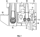
- FIGS. 5 and 6 show the SMA release assembly 60 in a first position, which corresponds to a non-actuated condition of the SMA release assembly 60.
- the SMA release assembly 60 includes an actuator base 62 that is positioned within the cavity 20 of the headrest assembly 10 and fixed therein.
- the actuator base 62 is formed of a non-metallic material, such as one comprising or consisting of plastic.
- a pulley wheel 64 is rotatably secured to the actuator base 62. In the illustrated embodiment, the pulley wheel 64 is positioned proximate an upper end of the actuator base 62.
- a length of SMA wire 68 is included and is anchored in adjacent electrical terminals 70 of a printed circuit board (PCB) 72.
- the PCB 72 is substantially smaller than the actuator base 62 and is operatively coupled thereto.
- the PCB 72 is coupled to the actuator base 62 proximate a lower end of the actuator base 62 with a plurality of retaining tabs 74 which are integrally formed with the actuator base 62 and protrude therefrom.
- the SMA wire 68 is formed in a loop, with the distal portion of the loop secured about a turnaround plug 76.
- the pulley wheel 64 is provided with two adjacent annular grooves in the periphery thereof to maintain spacing and separation of the wire portions from their adjacent counterparts.
- the SMA release assembly 60 also includes a slide 78 that is secured to the actuator base 62.
- the slide 78 is formed of a non-metallic material, such as one comprising or consisting of plastic, for example.
- a pair of tracks 80 protrude from the actuator base 62 to define a slot 82.
- a portion of the slide 78 is positioned within the slot 82 and is translatable therein in a substantially vertical manner, which is generally parallel to the longitudinal axis of the pull rod 48 ( FIGS. 3 and 4 ).
- the turnaround plug 76 is mounted on the lower extent of the slide 78, such that actuation of the SMA wire 68 causes it to contract and draw the slide 78 to translate upwardly.
- a drive arm 84 extends laterally from a lower portion of the slide 78 and is positioned to contact a follower pin 86 projecting from the distal end of the arm 42 of the release lever 41 ( FIGS. 3 and 4 ).
- a tension spring 88 is connected to the actuator base 62 and the slide 78 to resiliently bias the slide 78 downwardly toward the unactuated position of FIGS. 5 and 6 .
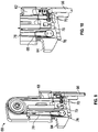
- the SMA actuator 60 is shown in a second position corresponding to an actuated condition which translates the slide 78 upwardly to rotate the release lever 41.
- the SMA release assembly 60 is activated by applying an electrical current to the SMA wire 68 through electrical terminals 70 to heat the wire 68, which causes it to contract when it surpasses a temperature threshold, which may be in the range of 75°C-100°C, for example.
- the contraction of the wire 68 applies tensile force to turnaround plug 76, causing the slide 78 to translate linearly upwardly.
- the drive arm 84 of slide 78 urges the follower pin 86 upwardly, thus rotating the release lever 41 and moving the pull rod 48 to rotate the lock pawl 37 and release the detent engagement of finger 39 in slot 34 ( FIGS. 3 and 4 ). Movement of the slide 78 to the second position shown in FIGS. 9 and 10 results in a portion of the slide 78 contacting a micro switch 79 to shut off the current, thereby allowing the SMA wire 68 to cool and expand to the position shown in FIGS. 5 and 6 .
- the micro switch 79 is mounted to the PCB 72.
- the springs 24 are enabled to rotate the housing 12 to the position of FIG. 2B .
- the housing 12 is restored to the upright, deployed position by manually rotating the housing 12 about the lateral portion 15 of the base portion 14. Finger 39 is urged by the spring forces to re-engage detent slot 34 to re-latch the housing in the upright position.
- the housing 12 further includes provisions to enable manual release of the latch mechanism 30 whenever desirable or necessary.
- a push button assembly 91 is secured in a sidewall portion of housing 12, and includes a cap 92 reciprocally translatably mounted on a cylindrical housing.
- the cap 92 is resiliently biased to extend outwardly, and a central plunger 93 is joined to the cap 92.
- the inner end of plunger 93 impinges on a distal portion of arm 43 of the release lever 41.
- the plunger 93 urges the distal end of arm 43 to rotate counter-clockwise, as viewed in FIGS. 3 and 4 .
- the pull rod 48 is translated upwardly to rotate the lock pawl 37 and release the detent engagement of finger 39 in slot 34.
- the springs 24 are enabled to rotate the housing 12 to the position of FIG. 2B . It is noted that since the follower pin 86 is not connected to arm 84 of the slide 78, no movement or force is applied to the SMA release assembly 60 when manual operation of the latch mechanism 30 is carried out.
- the SMA release assembly 60 is driven by power supplied through a power/control cable 96 that may be routed from the vehicle electrical power system through the base assembly 14 to the headrest assembly 10 ( FIGS. 4-10 ).
- the SMA release assembly 60 may be activated by remote command, using a standard communications protocol function that is built into the SMA release assembly 60. This may be accomplished by employing a button or touch pad on the dashboard of the vehicle, or through a personal communications device that is equipped to interact with the communications module of the actuator, for example.
- the PCB 72 may include a microprocessor that is programmed to manage the application of electrical power to the SMA wire 68, and to respond to communications protocols from the vehicle or the driver's commands. It is noted that the use of an SMA wire loop 68 serves to double the force generated by contraction of the wire 68 when heated beyond the threshold temperature, and also enables connecting the wire ends to fixed electrical terminals 70, so that any moving electrical contact is eliminated.
- an electrical push button may be provided in the headrest assembly 10 in addition to or in substitution to the manual push button assembly 91.
- the electrical push button is connected in the power circuit to the SMA release assembly 60, and may be employed to drive the SMA release assembly 60 to operate the latch mechanism 30 and lower the housing 12 from the deployed to the retracted position.
- the embodiments disclosed herein utilize the non-metallic actuator base 62 and slide 78 to reduce weight and cost of the SMA release assembly 60.
Landscapes
- Engineering & Computer Science (AREA)
- Mechanical Engineering (AREA)
- Aviation & Aerospace Engineering (AREA)
- Transportation (AREA)
- Chemical & Material Sciences (AREA)
- Combustion & Propulsion (AREA)
- General Engineering & Computer Science (AREA)
- Seats For Vehicles (AREA)
Applications Claiming Priority (1)
| Application Number | Priority Date | Filing Date | Title |
|---|---|---|---|
| US202163150384P | 2021-02-17 | 2021-02-17 |
Publications (1)
| Publication Number | Publication Date |
|---|---|
| EP4046865A1 true EP4046865A1 (de) | 2022-08-24 |
Family
ID=80682865
Family Applications (1)
| Application Number | Title | Priority Date | Filing Date |
|---|---|---|---|
| EP22157110.2A Withdrawn EP4046865A1 (de) | 2021-02-17 | 2022-02-16 | Kopfstützenverriegelung mit formgedächtnislegierungsauslösevorrichtung |
Country Status (2)
| Country | Link |
|---|---|
| US (1) | US20220258656A1 (de) |
| EP (1) | EP4046865A1 (de) |
Families Citing this family (11)
| Publication number | Priority date | Publication date | Assignee | Title |
|---|---|---|---|---|
| US11938853B2 (en) * | 2021-10-26 | 2024-03-26 | GM Global Technology Operations LLC | Multi-actuator capable headrest |
| US11912184B2 (en) | 2022-03-23 | 2024-02-27 | GM Global Technology Operations LLC | Cable sleeve for a foldable headrest |
| US12383066B2 (en) | 2022-04-26 | 2025-08-12 | Toyota Motor Engineering & Manufacturing North America, Inc. | Chair with shape memory material-based movement synchronized with visual content |
| DE102022120969A1 (de) * | 2022-08-19 | 2024-02-22 | Faurecia Autositze Gmbh | Verstellvorrichtung für eine Kopfstütze eines Fahrzeugsitzes und Fahrzeugsitz |
| US12241458B2 (en) | 2023-02-16 | 2025-03-04 | Toyota Motor Engineering & Manufacturing North America, Inc. | Actuator with contracting member |
| US12270386B2 (en) | 2023-02-16 | 2025-04-08 | Toyota Motor Engineering & Manufacturing North America, Inc. | Shape memory material member-based actuator |
| US12163507B2 (en) | 2023-02-22 | 2024-12-10 | Toyota Motor Engineering & Manufacturing North America, Inc. | Contracting member-based actuator with clutch |
| US12152570B2 (en) | 2023-02-22 | 2024-11-26 | Toyota Motor Engineering & Manufacturing North America, Inc. | Shape memory material member-based actuator with electrostatic clutch preliminary class |
| US12234811B1 (en) | 2023-08-21 | 2025-02-25 | Toyota Motor Engineering & Manufacturing North America, Inc. | Monitoring a state of a shape memory material member |
| US20250092862A1 (en) * | 2023-09-15 | 2025-03-20 | Toyota Motor Engineering & Manufacturing North America, Inc. | Shape memory material member anchor |
| US12589512B2 (en) | 2023-12-28 | 2026-03-31 | Toyota Motor Engineering & Manufacturing North America, Inc. | Shearing tool with closure assist |
Citations (2)
| Publication number | Priority date | Publication date | Assignee | Title |
|---|---|---|---|---|
| EP2407343A1 (de) * | 2009-03-10 | 2012-01-18 | Fujikura Ltd. | Vorrichtung zur einstellung der position einer kopfstüze und verfahren zur einstellung der position einer kopfstüze |
| US20150266401A1 (en) * | 2014-03-18 | 2015-09-24 | Bae Industries, Inc. | Headrest dump assembly with both cable and push button actuation |
Family Cites Families (13)
| Publication number | Priority date | Publication date | Assignee | Title |
|---|---|---|---|---|
| DE19939349A1 (de) * | 1999-08-19 | 2001-02-22 | Mannesmann Vdo Ag | Kopfstützenantrieb |
| US7556313B2 (en) * | 2005-11-04 | 2009-07-07 | Gm Global Technology Operations, Inc. | Active material actuated headrest assemblies |
| US8109567B2 (en) * | 2006-10-31 | 2012-02-07 | GM Global Technology Operations LLC | Active material actuated headrest utilizing bar linkage deployment system |
| US8851574B2 (en) * | 2009-05-06 | 2014-10-07 | Lear Corporation | Folding vehicle head restraint assembly |
| US8894142B2 (en) * | 2010-07-03 | 2014-11-25 | GM Global Technology Operations LLC | Stowable active material actuated rear seat headrest |
| US9785196B1 (en) * | 2016-08-18 | 2017-10-10 | Microsoft Technology Licensing, Llc | Capture connector for actuated locking devices |
| US20190168650A1 (en) * | 2017-12-01 | 2019-06-06 | Windsor Machine and Stamping (2009) Ltd. | Foldable head restraint |
| DE202018102797U1 (de) * | 2018-05-18 | 2019-05-22 | Alfmeier Präzision SE | Ventilanordnung und Pumpe mit integriertem Ventil für Lordosefunktion |
| US12353050B2 (en) * | 2018-08-07 | 2025-07-08 | Ningbo Sunny Opotech Co., Ltd | Camera apparatus, SMA driving device and manufacturing method, driving method and wiring method thereof |
| DE102019204782A1 (de) * | 2019-04-03 | 2020-10-08 | Rapitag Gmbh | Aktuatorelement und Verfahren zum Betreiben eines Aktuatorelements |
| EP3733451B1 (de) * | 2019-04-30 | 2022-07-13 | Lear Corporation | Aktuator |
| US11338715B2 (en) * | 2020-05-28 | 2022-05-24 | Mark A. Gummin | Shape memory alloy latch release mechanism for vehicle head restraint |
| TWI911320B (zh) * | 2020-11-20 | 2026-01-11 | 美商伊路米納有限公司 | 致動設備 |
-
2022
- 2022-02-16 EP EP22157110.2A patent/EP4046865A1/de not_active Withdrawn
- 2022-02-16 US US17/673,117 patent/US20220258656A1/en not_active Abandoned
Patent Citations (2)
| Publication number | Priority date | Publication date | Assignee | Title |
|---|---|---|---|---|
| EP2407343A1 (de) * | 2009-03-10 | 2012-01-18 | Fujikura Ltd. | Vorrichtung zur einstellung der position einer kopfstüze und verfahren zur einstellung der position einer kopfstüze |
| US20150266401A1 (en) * | 2014-03-18 | 2015-09-24 | Bae Industries, Inc. | Headrest dump assembly with both cable and push button actuation |
Also Published As
| Publication number | Publication date |
|---|---|
| US20220258656A1 (en) | 2022-08-18 |
Similar Documents
| Publication | Publication Date | Title |
|---|---|---|
| EP4046865A1 (de) | Kopfstützenverriegelung mit formgedächtnislegierungsauslösevorrichtung | |
| CN112078440B (zh) | 用于车辆座椅的翻移式装置 | |
| EP2216201B1 (de) | Elektrische Sitzsteuerungseinheit | |
| KR101363649B1 (ko) | 능동형 머리 지지대 시스템 | |
| US8851574B2 (en) | Folding vehicle head restraint assembly | |
| CN103038096B (zh) | 头枕,尤其用于汽车的头枕 | |
| US11338715B2 (en) | Shape memory alloy latch release mechanism for vehicle head restraint | |
| KR20050028311A (ko) | 형상기억 액츄에이터를 포함하는, 자동차 시트의구성요소를 위한 해제장치 | |
| US6957858B2 (en) | Dynamic flip-up head restraint | |
| US9132756B1 (en) | Head restraint assemblies | |
| US11319734B2 (en) | Unlocking unit having a variable trigger switch point | |
| US7484808B2 (en) | Vision improving system for a head restraint | |
| EP3988389A1 (de) | Kopfstützenanordnung mit verschiebbarem ratschenmechanismus | |
| KR100991236B1 (ko) | 자동차의 액티브 헤드레스트 | |
| EP2026995B1 (de) | Sicherheitsanordnung und verfahren zur montage einer sicherheitsanordnung | |
| CN110001462A (zh) | 车辆用座椅导轨 | |
| CN111231794B (zh) | 一种可调节的汽车座椅头枕及汽车座椅 | |
| US11235691B2 (en) | Actuating rear center head restraint | |
| US11897368B2 (en) | Floor lock release mechanism | |
| KR101028398B1 (ko) | 액티브 헤드레스트 | |
| JP2009101804A (ja) | 車両用シート及び車両用シートの製造方法 | |
| KR100764702B1 (ko) | 시트의 펌핑 및 리클라이닝 공용 레버 장치 | |
| JP5338279B2 (ja) | 乗物用シート | |
| CN111152692B (zh) | 一种座椅侧面碰撞断电机构及汽车电动座椅 | |
| KR20020068868A (ko) | 자동차용 헤드레스트 각도 조절장치 |
Legal Events
| Date | Code | Title | Description |
|---|---|---|---|
| PUAI | Public reference made under article 153(3) epc to a published international application that has entered the european phase |
Free format text: ORIGINAL CODE: 0009012 |
|
| STAA | Information on the status of an ep patent application or granted ep patent |
Free format text: STATUS: REQUEST FOR EXAMINATION WAS MADE |
|
| 17P | Request for examination filed |
Effective date: 20220216 |
|
| AK | Designated contracting states |
Kind code of ref document: A1 Designated state(s): AL AT BE BG CH CY CZ DE DK EE ES FI FR GB GR HR HU IE IS IT LI LT LU LV MC MK MT NL NO PL PT RO RS SE SI SK SM TR |
|
| GRAP | Despatch of communication of intention to grant a patent |
Free format text: ORIGINAL CODE: EPIDOSNIGR1 |
|
| STAA | Information on the status of an ep patent application or granted ep patent |
Free format text: STATUS: GRANT OF PATENT IS INTENDED |
|
| INTG | Intention to grant announced |
Effective date: 20230710 |
|
| STAA | Information on the status of an ep patent application or granted ep patent |
Free format text: STATUS: THE APPLICATION IS DEEMED TO BE WITHDRAWN |
|
| 18D | Application deemed to be withdrawn |
Effective date: 20231121 |