EP4046833B1 - Fahrzeug mit einem orientierungsflexiblen bodenwellensensor und verfahren zur kalibrierung dieses sensors - Google Patents
Fahrzeug mit einem orientierungsflexiblen bodenwellensensor und verfahren zur kalibrierung dieses sensors Download PDFInfo
- Publication number
- EP4046833B1 EP4046833B1 EP22158311.5A EP22158311A EP4046833B1 EP 4046833 B1 EP4046833 B1 EP 4046833B1 EP 22158311 A EP22158311 A EP 22158311A EP 4046833 B1 EP4046833 B1 EP 4046833B1
- Authority
- EP
- European Patent Office
- Prior art keywords
- vehicle
- sensor
- bump sensor
- suspension
- measurement
- Prior art date
- Legal status (The legal status is an assumption and is not a legal conclusion. Google has not performed a legal analysis and makes no representation as to the accuracy of the status listed.)
- Active
Links
Images


Classifications
-
- B—PERFORMING OPERATIONS; TRANSPORTING
- B62—LAND VEHICLES FOR TRAVELLING OTHERWISE THAN ON RAILS
- B62J—CYCLE SADDLES OR SEATS; AUXILIARY DEVICES OR ACCESSORIES SPECIALLY ADAPTED TO CYCLES AND NOT OTHERWISE PROVIDED FOR, e.g. ARTICLE CARRIERS OR CYCLE PROTECTORS
- B62J45/00—Electrical equipment arrangements specially adapted for use as accessories on cycles, not otherwise provided for
- B62J45/40—Sensor arrangements; Mounting thereof
- B62J45/42—Sensor arrangements; Mounting thereof characterised by mounting
- B62J45/423—Sensor arrangements; Mounting thereof characterised by mounting on or besides the wheel
-
- B—PERFORMING OPERATIONS; TRANSPORTING
- B60—VEHICLES IN GENERAL
- B60G—VEHICLE SUSPENSION ARRANGEMENTS
- B60G17/00—Resilient suspensions having means for adjusting the spring or vibration-damper characteristics, for regulating the distance between a supporting surface and a sprung part of vehicle or for locking suspension during use to meet varying vehicular or surface conditions, e.g. due to speed or load
- B60G17/015—Resilient suspensions having means for adjusting the spring or vibration-damper characteristics, for regulating the distance between a supporting surface and a sprung part of vehicle or for locking suspension during use to meet varying vehicular or surface conditions, e.g. due to speed or load the regulating means comprising electric or electronic elements
- B60G17/019—Resilient suspensions having means for adjusting the spring or vibration-damper characteristics, for regulating the distance between a supporting surface and a sprung part of vehicle or for locking suspension during use to meet varying vehicular or surface conditions, e.g. due to speed or load the regulating means comprising electric or electronic elements characterised by the type of sensor or the arrangement thereof
- B60G17/01908—Acceleration or inclination sensors
-
- B—PERFORMING OPERATIONS; TRANSPORTING
- B62—LAND VEHICLES FOR TRAVELLING OTHERWISE THAN ON RAILS
- B62J—CYCLE SADDLES OR SEATS; AUXILIARY DEVICES OR ACCESSORIES SPECIALLY ADAPTED TO CYCLES AND NOT OTHERWISE PROVIDED FOR, e.g. ARTICLE CARRIERS OR CYCLE PROTECTORS
- B62J45/00—Electrical equipment arrangements specially adapted for use as accessories on cycles, not otherwise provided for
- B62J45/20—Cycle computers as cycle accessories
-
- B—PERFORMING OPERATIONS; TRANSPORTING
- B62—LAND VEHICLES FOR TRAVELLING OTHERWISE THAN ON RAILS
- B62J—CYCLE SADDLES OR SEATS; AUXILIARY DEVICES OR ACCESSORIES SPECIALLY ADAPTED TO CYCLES AND NOT OTHERWISE PROVIDED FOR, e.g. ARTICLE CARRIERS OR CYCLE PROTECTORS
- B62J45/00—Electrical equipment arrangements specially adapted for use as accessories on cycles, not otherwise provided for
- B62J45/40—Sensor arrangements; Mounting thereof
- B62J45/41—Sensor arrangements; Mounting thereof characterised by the type of sensor
- B62J45/412—Speed sensors
-
- B—PERFORMING OPERATIONS; TRANSPORTING
- B62—LAND VEHICLES FOR TRAVELLING OTHERWISE THAN ON RAILS
- B62J—CYCLE SADDLES OR SEATS; AUXILIARY DEVICES OR ACCESSORIES SPECIALLY ADAPTED TO CYCLES AND NOT OTHERWISE PROVIDED FOR, e.g. ARTICLE CARRIERS OR CYCLE PROTECTORS
- B62J45/00—Electrical equipment arrangements specially adapted for use as accessories on cycles, not otherwise provided for
- B62J45/40—Sensor arrangements; Mounting thereof
- B62J45/41—Sensor arrangements; Mounting thereof characterised by the type of sensor
- B62J45/414—Acceleration sensors
-
- B—PERFORMING OPERATIONS; TRANSPORTING
- B62—LAND VEHICLES FOR TRAVELLING OTHERWISE THAN ON RAILS
- B62J—CYCLE SADDLES OR SEATS; AUXILIARY DEVICES OR ACCESSORIES SPECIALLY ADAPTED TO CYCLES AND NOT OTHERWISE PROVIDED FOR, e.g. ARTICLE CARRIERS OR CYCLE PROTECTORS
- B62J45/00—Electrical equipment arrangements specially adapted for use as accessories on cycles, not otherwise provided for
- B62J45/40—Sensor arrangements; Mounting thereof
- B62J45/41—Sensor arrangements; Mounting thereof characterised by the type of sensor
- B62J45/415—Inclination sensors
- B62J45/4151—Inclination sensors for sensing lateral inclination of the cycle
-
- B—PERFORMING OPERATIONS; TRANSPORTING
- B62—LAND VEHICLES FOR TRAVELLING OTHERWISE THAN ON RAILS
- B62J—CYCLE SADDLES OR SEATS; AUXILIARY DEVICES OR ACCESSORIES SPECIALLY ADAPTED TO CYCLES AND NOT OTHERWISE PROVIDED FOR, e.g. ARTICLE CARRIERS OR CYCLE PROTECTORS
- B62J45/00—Electrical equipment arrangements specially adapted for use as accessories on cycles, not otherwise provided for
- B62J45/40—Sensor arrangements; Mounting thereof
- B62J45/41—Sensor arrangements; Mounting thereof characterised by the type of sensor
- B62J45/415—Inclination sensors
- B62J45/4152—Inclination sensors for sensing longitudinal inclination of the cycle
-
- B—PERFORMING OPERATIONS; TRANSPORTING
- B60—VEHICLES IN GENERAL
- B60G—VEHICLE SUSPENSION ARRANGEMENTS
- B60G2204/00—Indexing codes related to suspensions per se or to auxiliary parts
- B60G2204/10—Mounting of suspension elements
- B60G2204/11—Mounting of sensors thereon
- B60G2204/116—Sensors coupled to the suspension arm
- B60G2204/1162—Sensors coupled to the suspension arm directly mounted on the suspension arm
-
- B—PERFORMING OPERATIONS; TRANSPORTING
- B60—VEHICLES IN GENERAL
- B60G—VEHICLE SUSPENSION ARRANGEMENTS
- B60G2300/00—Indexing codes relating to the type of vehicle
- B60G2300/12—Cycles; Motorcycles
-
- B—PERFORMING OPERATIONS; TRANSPORTING
- B60—VEHICLES IN GENERAL
- B60G—VEHICLE SUSPENSION ARRANGEMENTS
- B60G2400/00—Indexing codes relating to detected, measured or calculated conditions or factors
- B60G2400/80—Exterior conditions
- B60G2400/82—Ground surface
- B60G2400/821—Uneven, rough road sensing affecting vehicle body vibration
-
- B—PERFORMING OPERATIONS; TRANSPORTING
- B60—VEHICLES IN GENERAL
- B60G—VEHICLE SUSPENSION ARRANGEMENTS
- B60G2400/00—Indexing codes relating to detected, measured or calculated conditions or factors
- B60G2400/80—Exterior conditions
- B60G2400/82—Ground surface
- B60G2400/823—Obstacle sensing
-
- B—PERFORMING OPERATIONS; TRANSPORTING
- B60—VEHICLES IN GENERAL
- B60G—VEHICLE SUSPENSION ARRANGEMENTS
- B60G2500/00—Indexing codes relating to the regulated action or device
- B60G2500/10—Damping action or damper
-
- B—PERFORMING OPERATIONS; TRANSPORTING
- B60—VEHICLES IN GENERAL
- B60G—VEHICLE SUSPENSION ARRANGEMENTS
- B60G2800/00—Indexing codes relating to the type of movement or to the condition of the vehicle and to the end result to be achieved by the control action
- B60G2800/70—Estimating or calculating vehicle parameters or state variables
- B60G2800/702—Improving accuracy of a sensor signal
- B60G2800/7022—Calibration of a sensor, e.g. automatically
-
- B—PERFORMING OPERATIONS; TRANSPORTING
- B62—LAND VEHICLES FOR TRAVELLING OTHERWISE THAN ON RAILS
- B62J—CYCLE SADDLES OR SEATS; AUXILIARY DEVICES OR ACCESSORIES SPECIALLY ADAPTED TO CYCLES AND NOT OTHERWISE PROVIDED FOR, e.g. ARTICLE CARRIERS OR CYCLE PROTECTORS
- B62J45/00—Electrical equipment arrangements specially adapted for use as accessories on cycles, not otherwise provided for
- B62J45/40—Sensor arrangements; Mounting thereof
- B62J45/41—Sensor arrangements; Mounting thereof characterised by the type of sensor
-
- B—PERFORMING OPERATIONS; TRANSPORTING
- B62—LAND VEHICLES FOR TRAVELLING OTHERWISE THAN ON RAILS
- B62K—CYCLES; CYCLE FRAMES; CYCLE STEERING DEVICES; RIDER-OPERATED TERMINAL CONTROLS SPECIALLY ADAPTED FOR CYCLES; CYCLE AXLE SUSPENSIONS; CYCLE SIDECARS, FORECARS, OR THE LIKE
- B62K25/00—Axle suspensions
- B62K25/04—Axle suspensions for mounting axles resiliently on cycle frame or fork
- B62K2025/044—Suspensions with automatic adjustment
-
- G—PHYSICS
- G01—MEASURING; TESTING
- G01P—MEASURING LINEAR OR ANGULAR SPEED, ACCELERATION, DECELERATION, OR SHOCK; INDICATING PRESENCE, ABSENCE, OR DIRECTION, OF MOVEMENT
- G01P15/00—Measuring acceleration; Measuring deceleration; Measuring shock, i.e. sudden change of acceleration
-
- G—PHYSICS
- G01—MEASURING; TESTING
- G01P—MEASURING LINEAR OR ANGULAR SPEED, ACCELERATION, DECELERATION, OR SHOCK; INDICATING PRESENCE, ABSENCE, OR DIRECTION, OF MOVEMENT
- G01P21/00—Testing or calibrating of apparatus or devices covered by the preceding groups
Definitions
- the present invention relates to a vehicle and to a computer-implemented method for calibrating an orientationally flexible bump sensor.
- Vehicle suspension systems typically include a spring component or components and a damping component or components that form a suspension to provide for a comfortable ride, enhance performance of a vehicle, and the like. For example, a harder suspension is usually preferred on smooth terrain while a softer suspension is often the choice for an off-road environment.
- the suspension system is almost always a collection of compromises to obtain the "best" performance over a range of different possible encounters. Thus, as with every collection of compromises, an advancement in one area of a suspension system will often incur a new problem, set of problems, or performance changes/capabilities in another area.
- US 2019/187172 A discloses a self-calibrating sensor device.
- EP 2 130 721 A discloses a multifunctional safety, information and comfort device to be mounted on a vehicle, preferably a bicycle, comprising a rear-view mirror, an alphanumeric and iconographic display, sensors for measuring kinetic and environmental parameters, electronic components for measuring time and controlling said device, and an independent power supply.
- EP 2 567 839 discloses a device for determining an adjustment for a suspension component of a vehicle, which device comprises: a display; a memory storing computer-executable instructions; and a processor, the arrangement being such that when executed by the processor, the computer-executable instructions cause the device to: receive a weight value that indicates a load to be carried by the vehicle, determine a target pressure for an air spring of the suspension component based on the weight value, measure a loaded position of the suspension component, and determine an adjustment to the suspension component based on the loaded position and the target pressure.
- EP 2 248 691 A discloses a suspension system for a vehicle, which suspension system comprises: a damping assembly operatively connected to an actuator; a controller for controlling movement of said actuator whereby a damping rate of said damping assembly is adjusted by movement of the actuator; and a signal generating device remote from said damping assembly, which device, in use, provides an output electric signal representing a desired user adjustment to the damping rate of said damping assembly, said controller adapted to receive said electric signal and control said actuator to adjust said damping rate according to said electric signal, whereby said damping rate may be remotely altered during use of said vehicle.
- a vehicle comprising an orientationally flexible bump sensor, as set out in claim 1.
- the bump sensor may be an accelerometer.
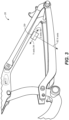
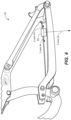
- the at least one bump sensor may be mounted to said vehicle at an orientation such that neither of said at least two axes of measurement are perpendicular to a ground plane.
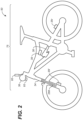
- the at least one bump sensor is mounted to a swingarm of said vehicle.
- the computer processor may be a microprocessor of said at least one bump sensor.
- the at least one bump sensor may have a wireless communication capability.
- the at least one bump sensor may have a wired communication capability.
- the method may further comprise mounting said bump sensor to said vehicle at an orientation such that neither of said at least two axes of measurement are perpendicular to a ground plane.
- the method may further comprise mounting said bump sensor to a swingarm of said vehicle.
- the method may further comprise evaluating said at least two axes of measurement and determining said gain value with a microprocessor of a suspension controller.
- the method may further comprise providing a wireless communication capability for said bump sensor.
- the method may further comprise providing a wired communication capability for said bump sensor.
- a suspension system for a vehicle provides a motion modifiable connection between a portion of the vehicle that is in contact with a surface and some or all of the rest of the vehicle that is not in contact with the surface.
- the portion of the vehicle that is in contact with the surface can include one or more wheel(s), skis, tracks, hulls, etc., while some or all of the rest of the vehicle that is not in contact with the surface include suspended portions such as anything on a frame, a seat, handlebars, engines, cranks, etc.
- the suspension In its basic form, the suspension is used to increase ride comfort, performance, endurance, component longevity and the like.
- the force of jarring events, rattles, vibrations, jostles, and the like which are encountered by the portion of the vehicle that is in contact with the surface are reduced or even removed as it transitions through the suspension before reaching suspended portions of the vehicle to include components such as seats, steering wheels/handlebars, pedals/foot pegs, fasteners, drive trains, engines, and the like.
- a portion of the wheel (or tire) will be in contact with the surface being traversed (e.g., pavement, dirt, gravel, sand, mud, rocks, etc.) while a shock assembly and/or other suspension system components will be coupled between a wheel retaining assembly and the suspended portion of the vehicle (often a portion of the vehicle frame and associated systems, the seat, handlebars, pedals, controls, steering wheel, interior, etc.).
- the surface being traversed e.g., pavement, dirt, gravel, sand, mud, rocks, etc.
- a shock assembly and/or other suspension system components will be coupled between a wheel retaining assembly and the suspended portion of the vehicle (often a portion of the vehicle frame and associated systems, the seat, handlebars, pedals, controls, steering wheel, interior, etc.).
- a portion of the track and/or the skis that will be in contact with the surface being traversed (e.g., snow, ice, etc.) while a shock assembly and/or other suspension components will be coupled between a track retaining assembly (and similarly the skis retaining assembly) and the suspended portion of the vehicle (usually including the engine and associated systems, the seat, handlebars, etc.).
- a portion of the hull will be in contact with the surface of the water while a shock assembly and/or other suspension components will be coupled between the hull and the suspended portion(s) of the vehicle (such as the seat, the handlebars, a portion of the vehicle frame, and/or the like).
- the airframe In an airplane in flight, it is the airframe that is in contact with the surface being traversed (e.g., the air) while a shock assembly and/or other suspension components will be coupled between the airframe and the suspended portion(s) of the vehicle (such as the seats and the like).
- the surface being traversed e.g., the air
- a shock assembly and/or other suspension components will be coupled between the airframe and the suspended portion(s) of the vehicle (such as the seats and the like).
- one or more shock assemblies of the suspension system can be adjusted for different characteristics based on the use type of the vehicle, terrain, purpose (e.g., rock crawl, normal use, race set-up, etc.), and the like.
- a downhill mountain bike rider motocross rider, off-road truck driver, side-by-side rider, snow machine racer, etc.
- a street bike racer (track racing vehicle, boat/PWC racer, etc.) would want a firmer suspension configuration with a very small range of motion to provide feel for the grip of the tire, maintain friction and/or aerodynamic geometries, and the like, in order to obtain the maximum performance from the vehicle.
- a suspension component there may be times where changes to a suspension component are desired during a given ride/drive. For example, a bike rider in a sprinting scenario would often want to firm up or possibly even lockout the suspension component to remove the opportunity for rider induced pedal bob. Similarly, a ride/drive from a paved road to an off-road environment (or vice-versa) would also be a time when a change to one or more suspension component settings is valuable.
- initial SAG settings refers to a pre-defined vehicle ride height and suspension geometry based on the initial compression of one or more shock assemblies of the suspension system for a given vehicle when it is within its normal load envelope configuration (e.g., with a rider/driver and any initial load weight).
- SAG Once the SAG is established for a vehicle, it will be the designated ride height of the vehicle, until and unless the SAG is changed.
- the initial SAG for a vehicle is usually established by the manufacturer.
- the vehicle SAG can then be modified and/or adjusted by an owner, a mechanic, or the like.
- an owner can modify the SAG to designate a new normal ride height based on a vehicle use purpose, load requirements that are different than the factory load configuration, an adjustment modification and/or replacement of one or more of the suspension components, a change in tire size, a performance adjustment, aesthetics, and the like.
- a bicycle is utilized as the example vehicle.
- the vehicle could be on any one of a variety of vehicles such as, but not limited to, a bicycle, a motorized bicycle, a motorcycle, a watercraft (e.g., boat, jet ski, PWC, etc.), a snow machine, a single wheeled vehicle, a multi-wheeled vehicle, a side-by-side, an on- and/or off-road vehicle, an aircraft, or the like.
- a motorized bicycle can include a bicycle with a combustion motor, an electric bicycle (e-bike), a hybrid electric and combustion bicycle, a hybrid motor and pedal powered bicycle, and the like.
- a bump sensor is used to identify an event, like a pothole on a road, or a rock or tree root on a trail that is encountered by a vehicle.
- an event like a pothole on a road, or a rock or tree root on a trail that is encountered by a vehicle.
- the suspension controller which then triggers an active valve in the suspension to switch the suspension to a softer (or even a softest) setting.
- the large spike in acceleration is reported by the front bump sensor to the suspension controller which triggers an active valve in the suspension to switch the suspension to a softer (or even a softest) setting.
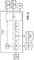
- Embodiments described herein disclose an orientationally flexible bump sensor that reduce installation complexity by allowing the bump sensor to be installed in different locations and with different orientations and provides a post installation calibration process to identify and adjust the signal from the bump sensor, such that the output from the bump sensor is equivalent to a bump sensor that is mounted to a vehicle with at least one measuring axis perpendicular to the ground plane 61.
- the wired sensor is an analog sensor 35 (e.g., without a microprocessor)
- the analog sensor could still partake in the calibration process, except instead of identifying the dominant axis, the dominant axis would be the axis that is providing the bump sensor signal to suspension controller 39. Then, as above, the magnitude gravity vector value of the predefined axis would be evaluated, the gain would be calculated and the resulting gain value would be used to make the bump sensor signal 1g.
- sensor 35 includes a receiver 333, an evaluator 335, a memory 336, a transmitter 338, a timer 337, and a power source 339.
- the acceleration (or other force) identified by an event 331 is analyzed locally at the sensor 35.
- a power source for sensor 35 is a CR2032 battery.
- power source is a different type of non-rechargeable battery.
- the power source is a rechargeable battery.
- the power source can be recharged wired or wirelessly.
- a power source having a wirelessly rechargeable capability means it could be charged using a wireless power transfer system. E.g., using an inductive charger (or the like) within a given distance of the wirelessly rechargeable capability of the battery.
- Examples of a wireless power transfer systems that could be used in one or more embodiments include those defined by the wireless power consortium (WPC) Qi standard, the AirFuel Alliance (e.g., Duracell Powermat, PowerKiss, etc.), WiTricity, and the like.
- WPC wireless power consortium
- AirFuel Alliance e.g., Duracell Powermat, PowerKiss, etc.
- WiTricity e.g., WiTricity, and the like.
- the power source is an energy harvesting switch that does not require a battery or other powered connection.
- the energy harvesting switch is capable of operating for an indefinite amount of time without requiring any type of recharge, battery change, etc.
- the energy harvesting switch utilizes a momentary generator such as ZF electronics AFIG-0007 to provide power.
- sensor data 301 broadcast by sensor 35 includes a unique identifier (ID) that identifies the specific sensor that broadcast the sensor data 301.
- ID unique identifier
- the suspension controller 39 will be able to identify which sensor 35 sent the signal based on the unique ID.
- the unique ID is used during the programming/pairing of sensor 35 with suspension controller 39.
- the one or more sensor(s) 35 transmit sensor data input 301 when an event is identified, as part of a cycle (e.g., a heartbeat check-in, etc.), as a radio event, or the like.
- a cycle e.g., a heartbeat check-in, etc.
- the wireless network is an intra-vehicle wireless network (such as a BAN) for data transmission between at least two components coupled with the vehicle, the at least two components including, but not limited to, at least one sensor, the suspension controller, and at least one peripheral device (such as a smart component, switch, or the like) coupled with the vehicle.
- the intra-vehicle wireless network is a wireless mesh network.
- the intra-vehicle wireless network includes an intra-vehicle transmission authentication and encryption protocol.
- sensor 35 when in standby state, sensor 35 will try to connect with suspension controller 39 at predefined times such as when a timer determines that it is time to send a heartbeat to suspension controller 39. In one embodiment, when in standby state, sensor 35 will try to connect with suspension controller 39 each time an event (or event above a predefined threshold) occurs and also try to connect with suspension controller 39 at predefined times such as when it is time to send a heartbeat to suspension controller 39.
- sensor 35 will remain in standby state until the connection with suspension controller 39 is established, or until sensor 35 determines there is a lack of movement. In one embodiment, if sensor 35 determines that the connection with suspension controller 39 is established (or re-established), sensor 35 will transition from standby state to an active state.
- sensor 35 if sensor 35 determines there is a lack of movement, sensor 35 will transition from standby state to a dormant state. In a dormant state, the bicycle is stationary and the sensor(s) 35 are reading no accelerations, e.g., a lack of movement. For instance, the bicycle is in storage or otherwise parked and not being ridden. In one embodiment, when in dormant state, the sensor(s) 35 go into low-power mode. In one embodiment, while in dormant state, the sensor 35 will periodically wake up to check for accelerations (e.g., the bicycle is being ridden) or movement. If there is a lack of movement (or accelerations), sensor 35 will return to the dormant state, e.g., go back to sleep. However, if the sensor 35 determines that there is movement (or accelerations) during the periodic wakeup, sensor 35 will change from the dormant state into either the standby state or the active state.
- suspension controller 39 includes a sensor data receiver 305, a sensor data evaluator 310, an active valve damper adjustor 313, a transmitter 325, and a timer 315.
- suspension controller 39 will use sensor data to generate suspension adjustments for damping assemblies via one or more of the active valves.
- the active valve in the damper assembly 288 (or the active valve in the damper assembly 38) will receive a signal from suspension controller 39 to adjust one or more flow paths to modify the damping characteristics of the damper. Additional information for vehicle suspension systems, sensors, and their components as well as adjustment, modification, and/or replacement aspects including manually, semi-actively, and/or actively controlled aspects and wired or wireless control thereof is provided in U.S. Patents 9,353,818 ; 9,682,604 ; 9,797,467 ; 10,415,662 to which reference is made.
- suspension controller 39 can also communicate wired or wirelessly with other devices such as another suspension controller, a mobile device, a computing system, and/or any other smart component(s) within a transmission range of suspension controller 39.
- suspension controller 39 could communicate with a suspension controller on a second vehicle, or any number of suspension controllers on any number of vehicles within range of suspension controller 39.
- one or more suspension controllers on each of the bicycles could be communicating wirelessly such that the suspension information from the lead bike is also provided to the follow bicycle(s) (or automobiles, motorcycles, ATVs, snowmobiles, water vehicles, and the like).
- the suspension information from the lead vehicle can be used as future suspension information to the follow vehicle(s).
- the front vehicle information is provided to the follow vehicle(s) a short time prior to the follow vehicle(s) actually reaching the location of the suspension event (or terrain, etc.) that the front vehicle has already encountered. This would allow a suspension controller 39 on a follow vehicle to use the active valve adjustment to prepare the damper for the upcoming terrain or event.
- suspension controller 39 could have different modes such as open, auto, and lock out (different levels of bump sensing, or some combination thereof).
- the lock out mode would be a "sprint" type setting that would lock-out the suspension, providing no bump sensing and removing the opportunity for pedal bob.
- the suspension would be a softer suspension that does not use any (or uses only limited bump sensing for the most major of suspension events).
- the suspension controller 39 would operate in the "best" configuration. Such a “best” configuration could be based on terrain, rider, riding style, bicycle type, ride length, ride purpose, etc. For example, a “best” mode for a downhill mountain bike race would be a very active suspension configuration with a large range of motion, a "best" mode for a street race would be a firm suspension configuration with a very small range of motion, a "best” mode for a Sunday afternoon street ride would be a soft suspension configuration, etc. Although three suspension modes are discussed, in one embodiment, suspension controller 39 may have more or fewer modes, or operate with more or less granularity.
- the IVI system may be integrated with the vehicle structure, suspension components, suspension controller(s) and data processing system as described in U.S. Pat. Nos. 7,484,603 ; 8,838,335 ; 8,955,653 ; 9,303,712 ; 10,060,499 ; 10,443,671 ; and 10,737,546 ; to which reference is made.
- the IVI system could incorporate vehicle systems consisting of one or more sensor(s), imagers, active valves, active damping components, suspension controllers and the like. The principles of patents and other documents mentioned herein, may be integrated one or more embodiments hereof, individually or in combination, as disclosed herein.
- suspension controller 39 receives sensor data input 301 from one or more sensor(s) 35 and outputs a suspension adjustment command 328, a suspension return command 326, and information 329.
- the receipt of sensor data 301 would cause suspension controller 39 to instantly (or nearly instantly) soften the active suspension of one or more of the active dampers.
- suspension controller 39 For example, if the vehicle is about to, or is encountering an event such as a rock, root, bump, curb, pothole, or the like that causes a force above a certain threshold to be felt at the tire (such as the front tire) sensor data 301 would describe an event which identifies as an event that suspension controller 39 should respond to by changing one or more active dampers into a softer mode (e.g., active damper 288) such that the force imparted by the event would be reduced before it is felt at the handlebars (or the seat, pedals, etc.).
- a softer mode e.g., active damper 288
- information 329 may be additional information in addition to the message received indication.
- information 329 will include information such as event threshold values, upcoming changes to event threshold values, and the like.
- timer 315 begins to toll when the sensor data 301 about the event is received. In one embodiment, the timer 315 will run for a certain amount of time. In one embodiment, the timer 315 is 0.5 seconds. However, in one embodiment, the timer could be set to another value or could be a value that is dependent upon location, terrain, or the like. In one embodiment, the length of time measured by the timer 315 is fixed e.g., set by a manufacturer. In one embodiment, the length of time measured by the timer 315 is adjustable by a manufacturer, a user, a mechanic, a technician, or the like.
- timer 315 will trigger a suspension return command 326 that will be transmitted to the damper (e.g., front fork damper 288 in this example).
- the active damper will dismiss the suspension adjustment command 328 override.
- the suspension return command 326 will include information that will cause the active damper to return to its previous firmness settings, to a preprogrammed setting, to a new setting automatically determined by suspension controller 39, to a location-based setting, a terrain-based setting, or the like.
- bump sensor 35 sends sensor data 301 to suspension controller 39.
- Suspension controller 39 opens the suspension (e.g., softens the damping of damper 288).
- the bump sensor continues to send sensor data 301 at a rate of 10 Hz.
- the timer 315 is resetting as each sensor data 301 packet is received.
- timer 315 is not reset and is allowed to run down to zero.
- the suspension return command 326 is triggered and sent by transmitter 325 to the one or more active damper components.
- the suspension return command 326 is triggered and sent by transmitter 325 3.5 seconds after the first sensor data 301 message was received (e.g., 3 seconds of sensor data 301 messages plus the 0.5 second timer clock).
- the wireless communication pairing is made resistant against attempts made by unauthorized actors trying to attack and control the system by performing authentication and encryption between the wireless components.
- system attacks include, but are not limited to, replay attacks, impersonation, denial of service, and the like.
- DLE is enabled, LE 2M PHY is used, notifications and writes without responses is enabled, the ATT MTU value is set to be at least greater than 247 bytes, and the connection interval is set to allow for the maximum number of packets per connection interval.
- the wireless communications protocols and optimization capabilities utilize communication interference resolution techniques such as frequency hopping, spread spectrum operations, code-division multiple access (CDMA), global system for mobiles (GSM), and the like to maintain BAN, intra-vehicle, and or inter-vehicle communication operations in a busy environment (e.g., at a race, gathering, rally, ride, festival, or the like). For example, when a plurality of different vehicles are within the same vicinity/spectrum and some or all of the vehicles have wireless communications occurring thereon.
- communication interference resolution techniques such as frequency hopping, spread spectrum operations, code-division multiple access (CDMA), global system for mobiles (GSM), and the like to maintain BAN, intra-vehicle, and or inter-vehicle communication operations in a busy environment (e.g., at a race, gathering, rally, ride, festival, or the like).
- the communications module is a BMD-350.
- a BMD-350 module is disclosed herein as one embodiment of a communications module used in the present discussion, it should be appreciated that another embodiment may utilize a different communications module and/or different components, protocols, and the like.
- BMD-350 is a stand-alone Bluetooth 5 low energy (LE) module that can be used individually or as part of a Bluetooth mesh.
- BMS-350 is an ultra-low power module based on the nRF52832 SoC from Nordic Semiconductor.
- BMD-350 has an Arm ® Cortex ® -M4 with FPU 32-bit processor, embedded 2.4GHz transceiver, and integrated antenna, to provide a complete RF.
- BMD-350 radio frequency range is 2.360 GHz to 2.500 GHz; the modulations are gaussian frequency-shift keying (GFSK) at 1 Mbps, 2 Mbps data rates.
- BMD-350 has a transmit power +4 dBm maximum, a receiver sensitivity -96 dBm (LE mode), and a ceramic chip antenna (1 dBi peak).
- BMD-350 with the nRF52832 SoC supports the S132 (Bluetooth low energy Central and Peripheral), S212 (ANT) and S312 (ANT and Bluetooth low energy) SoftDevices.
- the ESB protocol (or similar ISM Band Technology) takes over.
- an active identifies a component that is adjustable, manipulatable, etc., during typical operation of the valve.
- an active valve or live valve, etc.
- an active valve can have its operation changed to thereby alter a corresponding damping characteristic from a "soft" damping setting to a “firm” damping setting by, for example, adjusting a switch in a passenger compartment of a vehicle.
- an active valve may also be configured to automatically adjust its operation, and corresponding damping characteristics, based upon, for example, operational information pertaining to the vehicle and/or the suspension with which the valve is used.
- an active valve may be configured to automatically adjust its operation, and corresponding damping characteristics, to provide damping based upon received user input settings (e.g., a user-selected "comfort” setting, a user-selected “sport” setting, and the like).
- an "active” valve is adjusted or manipulated electronically (e.g., using a powered solenoid, or the like) to alter the operation or characteristics of a valve and/or other component.
- valve or damping component identifies a component that is manually adjustable, physically manipulatable, etc., without requiring disassembly of the valve, damping component, or suspension damper which includes the valve or damping component.
- manual adjustment or physical manipulation of the valve, damping component, or suspension damper, which includes the valve or damping component occurs when the valve is in use.
- a manual valve may be adjusted to change its operation to alter a corresponding damping characteristic from a "soft" damping setting to a “firm” damping setting by, for example, manually rotating a knob, pushing or pulling a lever, physically manipulating an air pressure control feature, manually operating a cable assembly, physically engaging a hydraulic unit, and the like.
- manual adjustment/physical manipulation of the valve or component can occur before, during, and/or after "typical operation of the vehicle".
- a vehicle suspension may also be referred to using one or more of the terms “passive”, “active”, “semi-active” or “adaptive”.
- active suspension refers to a vehicle suspension which controls the movement of the wheels (or other terrain encountering component) relative to the suspended portion of the vehicle.
- active suspensions may be defined as either a “pure active suspension” or a “semi-active suspension” (a “semi-active suspension” is also sometimes referred to as an “adaptive suspension”).
- a motive source such as, for example, an actuator
- a wheel with respect to the vehicle In a “pure active suspension”, a motive source such as, for example, an actuator, is used to move a wheel with respect to the vehicle.
- no motive force/actuator is employed to adjust the movement of the wheels (or other terrain encountering component) relative to the suspended portion of the vehicle.
- the characteristics of the suspension e.g., the firmness of the suspension
- passive suspension refers to a vehicle suspension in which the characteristics of the suspension are not changeable during typical use, and no motive force/actuator is employed to adjust the movement of the wheels (or other terrain encountering component) relative to the suspended portion of the vehicle.
- active valve as defined above, is well suited for use in a “pure active suspension” or a “semi-active suspension”.
- a transducer such as an accelerometer measures other aspects of the vehicle's suspension system, like axle force and/or moments applied to various parts of the vehicle, like steering tie rods, and provides sensor data that would ultimately cause the active valve to modify one or more characteristics of a suspension component (e.g., an active damper).
- a suspension component e.g., an active damper
- a pressure transducer measuring pressure in a vehicle tire will provide sensor data that would ultimately cause the active valve to modify one or more characteristics of a suspension component (e.g., an active damper).
- a suspension component e.g., an active damper
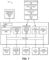
- suspension controller 39 can include some or all of the components of computer system 700.
- these devices can include wired and/or wireless communication capabilities as described herein.
Landscapes
- Engineering & Computer Science (AREA)
- Mechanical Engineering (AREA)
- Vehicle Body Suspensions (AREA)
- Length Measuring Devices With Unspecified Measuring Means (AREA)
- Measuring And Recording Apparatus For Diagnosis (AREA)
- Photoreceptors In Electrophotography (AREA)
- Cutting Tools, Boring Holders, And Turrets (AREA)
Claims (13)
- Fahrzeug (50), umfassend einen orientierungsflexiblen Bodenwellensensor, wobei der orientierungsflexible Bodenwellensensor Folgendes umfasst:mindestens einen Bodenwellensensor (35), der an dem Fahrzeug montiert ist, wobei der mindestens eine Bodenwellensensor mindestens zwei Messachsen (93, 94) umfasst und angepasst ist, um in einen Kalibrierungszustand gebracht zu werden; undeinen Computerprozessor;dadurch gekennzeichnet, dass der Computerprozessor konfiguriert ist, um:den mindestens einen Bodenwellensensor (35) in den Kalibrierungszustand zu bringen, wenn das Fahrzeug derart positioniert ist, dass es sich auf relativ flachem Boden befindet und relativ gerade nach oben und unten ist, sodass das Fahrzeug im Wesentlichen senkrecht zu der flachen Bodenebene ausgerichtet ist;die mindestens zwei Messachsen (93, 94) auszuwerten, um zu bestimmen, welche Achse der mindestens zwei Messachsen einen Vektor höchster Größe aufweist;die Messachse mit dem Vektor höchster Größe als die bezeichnete Achse zu bezeichnen, die als ein Bodenwellensensorsignal überwacht werden soll;einen Verstärkungswert zu bestimmen, um zu bewirken, dass der Vektor höchster Größe etwa 1 g beträgt;der Achse mit dem Vektor höchster Größe den Verstärkungswert zuzuweisen; undden mindestens einen Bodenwellensensor (35) von dem Kalibrierungszustand in einen Betriebsmodus zu bewegen, in dem der Verstärkungswert auf jede Messung angewendet wird, die durch die Achse mit dem Vektor höchster Größe erzeugt wird, wodurch das Bodenwellensensorsignal unter Verwendung der bezeichneten Achse, die durch den Computerprozessor ausgewählt wird, überwacht wird.
- Fahrzeug nach Anspruch 1, wobei der mindestens eine Bodenwellensensor (35) an dem Fahrzeug in einer derartigen Ausrichtung montiert ist, dass keine der mindestens zwei Messachsen (93, 94) senkrecht zu einer Bodenebene ist; und/oder
wobei der mindestens eine Bodenwellensensor an einer Schwinge (26) des Fahrzeugs (50) montiert ist. - Fahrzeug nach Anspruch 1 oder 2, wobei der Computerprozessor konfiguriert ist, um den Verstärkungswert unveränderlich zu halten, bis der mindestens eine Bodenwellensensor (35) das nächste Mal in den Kalibrierungszustand gebracht wird.
- Fahrzeug nach Anspruch 1, 2 oder 3, wobei der Computerprozessor ein Mikroprozessor des mindestens einen Bodenwellensensors oder ein Mikroprozessor einer Aufhängungssteuereinheit ist.
- Fahrzeug nach einem der vorhergehenden Ansprüche, wobei der mindestens eine Bodenwellensensor (35) eine drahtlose Kommunikationsfähigkeit aufweist; und/oder wobei der mindestens eine Bodenwellensensor (35) eine drahtgebundene Kommunikationsfähigkeit aufweist.
- Fahrzeug nach einem der vorhergehenden Ansprüche, wobei der mindestens eine Bodenwellensensor (35) drei Messachsen (93, 94, 95) umfasst.
- Fahrzeug nach Anspruch 6, wobei der mindestens eine Bodenwellensensor (35) an dem Fahrzeug (50) in einer derartigen Ausrichtung montiert ist, dass keine der drei Messachsen (93, 94, 95) senkrecht zu einer Bodenebene ist.
- Computerimplementiertes Verfahren zur Kalibrierung eines orientierungsflexiblen Bodenwellensensors, dadurch gekennzeichnet, dass das Verfahren mit einem Computerprozessor Folgendes umfasst:Bringen eines Bodenwellensensors (35), der an einem Fahrzeug (50) montiert ist, in einen Kalibrierungszustand, wenn das Fahrzeug derart positioniert ist, dass es sich auf relativ flachem Boden befindet und relativ gerade nach oben und unten ist, sodass das Fahrzeug im Wesentlichen senkrecht zu der flachen Bodenebene ausgerichtet ist;Erzeugen von mindestens zwei Messachsen (93, 94) von dem Bodenwellensensor (35);Auswerten der mindestens zwei Messachsen (93, 94), um zu bestimmen, welche Achse der mindestens zwei Messachsen einen Vektor höchster Größe aufweist;Bezeichnen der Messachse mit dem Vektor höchster Größe als die bezeichnete Achse, die als ein Bodenwellensensorsignal überwacht werden soll;Bestimmen eines Verstärkungswerts, um zu bewirken, dass der Vektor höchster Größe etwa 1 g beträgt; undZuweisen des Verstärkungswerts zu der Achse mit dem Vektor höchster Größe;Bewegen des mindestens einen Bodenwellensensors (35) von dem Kalibrierungszustand in einen Betriebsmodus, in dem der Verstärkungswert auf alle Messungen angewendet wird, die durch die Achse mit dem Vektor höchster Größe erzeugt werden, wodurch das Bodenwellensensorsignal unter Verwendung der bezeichneten Achse, die durch den Computerprozessor ausgewählt wird, überwacht wird.
- Computerimplementiertes Verfahren nach Anspruch 8, ferner umfassend:
Montieren des Bodenwellensensors (35) an dem Fahrzeug in einer derartigen Ausrichtung, dass keine der mindestens zwei Messachsen (93, 94) senkrecht zu einer Bodenebene ist; und/oder Montieren des Bodenwellensensors (35) an einer Schwinge (26) des Fahrzeugs (50). - Computerimplementiertes Verfahren nach Anspruch 8 oder 9, ferner umfassend:
Halten des Verstärkungswerts unveränderlich, bis der Bodenwellensensor (35) das nächste Mal in den Kalibrierungszustand gebracht wird. - Computerimplementiertes Verfahren nach Anspruch 8, 9 oder 10, ferner umfassend:
Auswerten der mindestens zwei Messachsen (93, 94) und Bestimmen des Verstärkungswerts mit einem Mikroprozessor des Bodenwellensensors oder mit einem Mikroprozessor einer Aufhängungssteuereinheit. - Computerimplementiertes Verfahren nach einem der Ansprüche 8 bis 11, ferner umfassend:Bereitstellen einer drahtlosen Kommunikationsfähigkeit für den Bodenwellensensor (35); und/oderBereitstellen einer drahtgebundenen Kommunikationsfähigkeit für den Bodenwellensensor (35).
- Verfahren nach einem der Ansprüche 8 bis 12, wobei:das Erzeugen das Erzeugen von drei Messachsen (93, 94, 95) von dem Bodenwellensensor (35) umfasst; unddas Auswerten das Auswerten der drei Messachsen (93, 94, 95) umfasst, um zu bestimmen, welche Achse der drei Messachsen einen Vektor höchster Größe aufweist;und optional ferner umfassend den folgenden Schritt:
Montieren des Bodenwellensensors (35) an dem Fahrzeug (50) in einer derartigen Ausrichtung, dass keine der drei Messachsen senkrecht zu einer Bodenebene ist.
Applications Claiming Priority (2)
| Application Number | Priority Date | Filing Date | Title |
|---|---|---|---|
| US202163152668P | 2021-02-23 | 2021-02-23 | |
| US17/673,806 US12466508B2 (en) | 2021-02-23 | 2022-02-17 | Orientationally flexible bump sensor |
Publications (2)
| Publication Number | Publication Date |
|---|---|
| EP4046833A1 EP4046833A1 (de) | 2022-08-24 |
| EP4046833B1 true EP4046833B1 (de) | 2025-07-02 |
Family
ID=80448624
Family Applications (1)
| Application Number | Title | Priority Date | Filing Date |
|---|---|---|---|
| EP22158311.5A Active EP4046833B1 (de) | 2021-02-23 | 2022-02-23 | Fahrzeug mit einem orientierungsflexiblen bodenwellensensor und verfahren zur kalibrierung dieses sensors |
Country Status (3)
| Country | Link |
|---|---|
| US (1) | US12466508B2 (de) |
| EP (1) | EP4046833B1 (de) |
| TW (2) | TWI893487B (de) |
Cited By (1)
| Publication number | Priority date | Publication date | Assignee | Title |
|---|---|---|---|---|
| US12466508B2 (en) | 2021-02-23 | 2025-11-11 | Fox Factory, Inc. | Orientationally flexible bump sensor |
Families Citing this family (8)
| Publication number | Priority date | Publication date | Assignee | Title |
|---|---|---|---|---|
| US11833876B2 (en) * | 2020-07-15 | 2023-12-05 | Fox Factory, Inc. | Rough road detection |
| US12065214B2 (en) * | 2020-12-28 | 2024-08-20 | Fox Factory, Inc. | Wireless active suspension system |
| US11858588B2 (en) | 2021-04-29 | 2024-01-02 | Shimano Inc. | Rear sprocket assembly and lock device |
| US20240051638A1 (en) * | 2022-08-09 | 2024-02-15 | Ming-Ta Tsai | Bicycle automatic shock absorbing device |
| US20240343337A1 (en) * | 2022-08-09 | 2024-10-17 | Ming-Ta Tsai | Control device and method of a bicycle automatic shock absorber |
| CN115303227A (zh) * | 2022-08-26 | 2022-11-08 | 惠州市德赛西威智能交通技术研究院有限公司 | 一种数字钥匙配对方法,配对系统,数字钥匙和汽车 |
| AT526497A1 (de) * | 2022-09-14 | 2024-03-15 | Ktm Ag | Fahrzeug mit datenerfassungseinheit |
| US11904978B1 (en) * | 2023-09-07 | 2024-02-20 | Manoj Apte | Hybridized mountain bike suspension |
Family Cites Families (43)
| Publication number | Priority date | Publication date | Assignee | Title |
|---|---|---|---|---|
| GB8610842D0 (en) | 1986-05-02 | 1986-06-11 | Bl Tech Ltd | Suspension system |
| DE19751839A1 (de) | 1997-11-22 | 1999-05-27 | Bosch Gmbh Robert | Verfahren und Vorrichtung zur Erkennung einer Kipptendenz eines Fahrzeuges |
| US7128192B2 (en) | 2001-08-30 | 2006-10-31 | Fox Factory, Inc. | Inertia valve shock absorber |
| TW200900275A (en) | 2007-06-29 | 2009-01-01 | Kwang Yang Motor Co | Suspension control method of motorcycle and device thereof |
| US20100244340A1 (en) | 2008-03-19 | 2010-09-30 | Wootten Dennis K | Methods and apparatus for combined variable damping and variable spring rate suspension |
| US9033122B2 (en) | 2009-01-07 | 2015-05-19 | Fox Factory, Inc. | Method and apparatus for an adjustable damper |
| US20100170760A1 (en) | 2009-01-07 | 2010-07-08 | John Marking | Remotely Operated Bypass for a Suspension Damper |
| US9239090B2 (en) | 2009-01-07 | 2016-01-19 | Fox Factory, Inc. | Suspension damper with remotely-operable valve |
| US9452654B2 (en) | 2009-01-07 | 2016-09-27 | Fox Factory, Inc. | Method and apparatus for an adjustable damper |
| US8857580B2 (en) | 2009-01-07 | 2014-10-14 | Fox Factory, Inc. | Remotely operated bypass for a suspension damper |
| US8627932B2 (en) | 2009-01-07 | 2014-01-14 | Fox Factory, Inc. | Bypass for a suspension damper |
| US10060499B2 (en) | 2009-01-07 | 2018-08-28 | Fox Factory, Inc. | Method and apparatus for an adjustable damper |
| US10047817B2 (en) | 2009-01-07 | 2018-08-14 | Fox Factory, Inc. | Method and apparatus for an adjustable damper |
| US8550223B2 (en) | 2008-05-09 | 2013-10-08 | Fox Factory, Inc. | Methods and apparatus for position sensitive suspension dampening |
| ITMI20081038A1 (it) | 2008-06-06 | 2009-12-07 | Selle Italia Srl | Dispositivo multifunzionale per veicoli |
| US20100276906A1 (en) * | 2009-05-04 | 2010-11-04 | Mario Galasso | Suspension system for a vehicle |
| US9140325B2 (en) | 2009-03-19 | 2015-09-22 | Fox Factory, Inc. | Methods and apparatus for selective spring pre-load adjustment |
| US10036443B2 (en) | 2009-03-19 | 2018-07-31 | Fox Factory, Inc. | Methods and apparatus for suspension adjustment |
| EP2312180B1 (de) | 2009-10-13 | 2019-09-18 | Fox Factory, Inc. | Vorrichtung zur Steuerung eines hydraulischen Dämpfers |
| TW201114633A (en) | 2009-10-28 | 2011-05-01 | Chunghwa Telecom Co Ltd | System and method for automatically detecting and collecting road flatness |
| EP3567272B1 (de) | 2011-09-12 | 2021-05-26 | Fox Factory, Inc. | Verfahren und vorrichtung zur aufhängungseinstellung |
| US9026263B2 (en) | 2011-11-30 | 2015-05-05 | Alpine Electronics, Inc. | Automotive navigation system and method to utilize internal geometry of sensor position with respect to rear wheel axis |
| US8770592B2 (en) | 2012-02-03 | 2014-07-08 | Fox Factory, Inc. | Suspension with hydraulic preload adjust |
| TW201430781A (zh) | 2013-01-21 | 2014-08-01 | Chunghwa Telecom Co Ltd | 一重力感測器實現路況障礙分析系統與方法 |
| US9702349B2 (en) * | 2013-03-15 | 2017-07-11 | ClearMotion, Inc. | Active vehicle suspension system |
| GB2518676B (en) * | 2013-09-28 | 2019-04-10 | Quartix Ltd | Telematics system and associated method |
| EP3123209B1 (de) | 2014-03-28 | 2023-09-06 | 2241781 Ontario Inc. | Absolutvektor-gravimeter und verfahren zur messung eines absoluten schwerkraftvektors |
| US20150305426A1 (en) * | 2014-04-25 | 2015-10-29 | Ford Global Technologies, Llc | Bicycle helmet with integrated electronics |
| CN104075699B (zh) | 2014-07-07 | 2016-06-29 | 温州大学 | 三维固态电子罗盘及其传感器的零点和比例系数核正方法 |
| EP3048025A1 (de) | 2015-01-20 | 2016-07-27 | Harman Becker Automotive Systems GmbH | Fahrerinformationssystem für Zweiräder |
| DE102015209132A1 (de) | 2015-05-19 | 2016-11-24 | Robert Bosch Gmbh | Verfahren zum Betreiben eines Inertialsensors und eines Fahrzeugs, Fahrzeug |
| CN106323226B (zh) | 2015-06-19 | 2018-09-25 | 中船航海科技有限责任公司 | 一种利用北斗测定惯性导航系统与测速仪安装夹角的方法 |
| CN105912850B (zh) | 2016-04-07 | 2019-01-01 | 浙江漫思网络科技有限公司 | 一种基于g-sensor的优化轨迹数据数据量的方法 |
| US10737546B2 (en) | 2016-04-08 | 2020-08-11 | Fox Factory, Inc. | Electronic compression and rebound control |
| CN109906425B (zh) * | 2016-11-11 | 2022-05-27 | 索尼公司 | 信息处理设备 |
| CN106530696B (zh) | 2016-11-17 | 2019-07-26 | 捷开通讯(深圳)有限公司 | 一种驾驶行为监控方法及路况监控方法 |
| TWM546323U (zh) | 2017-03-17 | 2017-08-01 | 方成未來股份有限公司 | 懸吊控制模組、懸吊系統與交通工具 |
| US9958473B1 (en) * | 2017-05-01 | 2018-05-01 | Smartdrive Systems, Inc. | Calibrating sensor unit orientation for use in a vehicle monitoring system |
| JP7236799B2 (ja) * | 2017-07-11 | 2023-03-10 | 株式会社シマノ | 自転車用制御装置およびこれを備える自転車用サスペンションシステム |
| US10933710B2 (en) | 2017-09-29 | 2021-03-02 | Fox Factory, Inc. | Modular electronic damping control |
| US11156631B2 (en) * | 2017-12-14 | 2021-10-26 | Invensense, Inc. | Sensor self-calibration |
| US11253216B2 (en) * | 2020-04-28 | 2022-02-22 | Globus Medical Inc. | Fixtures for fluoroscopic imaging systems and related navigation systems and methods |
| US12466508B2 (en) | 2021-02-23 | 2025-11-11 | Fox Factory, Inc. | Orientationally flexible bump sensor |
-
2022
- 2022-02-17 US US17/673,806 patent/US12466508B2/en active Active
- 2022-02-22 TW TW112140012A patent/TWI893487B/zh active
- 2022-02-22 TW TW111106424A patent/TWI823265B/zh active
- 2022-02-23 EP EP22158311.5A patent/EP4046833B1/de active Active
Cited By (1)
| Publication number | Priority date | Publication date | Assignee | Title |
|---|---|---|---|---|
| US12466508B2 (en) | 2021-02-23 | 2025-11-11 | Fox Factory, Inc. | Orientationally flexible bump sensor |
Also Published As
| Publication number | Publication date |
|---|---|
| TWI893487B (zh) | 2025-08-11 |
| EP4046833A1 (de) | 2022-08-24 |
| TW202406767A (zh) | 2024-02-16 |
| US20220266939A1 (en) | 2022-08-25 |
| US12466508B2 (en) | 2025-11-11 |
| TW202237428A (zh) | 2022-10-01 |
| TWI823265B (zh) | 2023-11-21 |
Similar Documents
| Publication | Publication Date | Title |
|---|---|---|
| EP4046833B1 (de) | Fahrzeug mit einem orientierungsflexiblen bodenwellensensor und verfahren zur kalibrierung dieses sensors | |
| EP4021029B1 (de) | Remote-gerät mit niedriger latenz und niedrigem stromverbrauch für eine aktive komponente | |
| US12428098B2 (en) | Wireless active suspension system | |
| US20240092135A1 (en) | Wireless electronic shock assembly | |
| US12429106B2 (en) | Wireless active suspension system with at least one wireless sensor coupled with at least one unsprung mass | |
| EP4112969B1 (de) | Einstellbare stossanordnung | |
| EP4108557B1 (de) | Elektronisch betätigte kippsattelstütze | |
| US20250014393A1 (en) | Connected component platform | |
| US12350991B2 (en) | Plug and play suspension | |
| US20250276552A1 (en) | Rough road detection | |
| EP3939812B1 (de) | Computer-implementiertes system und verfahren zur modifizierung eines aktiven ventildämpfers eines fahrzeugaufhängungssystems | |
| US20250354594A1 (en) | Electronic modal base valve | |
| US20260054791A1 (en) | Modifying operational aspects of a suspension control system | |
| US12384213B2 (en) | Hot-start suspension tune | |
| US20250153789A1 (en) | Remote electronic shock adjuster |
Legal Events
| Date | Code | Title | Description |
|---|---|---|---|
| PUAI | Public reference made under article 153(3) epc to a published international application that has entered the european phase |
Free format text: ORIGINAL CODE: 0009012 |
|
| STAA | Information on the status of an ep patent application or granted ep patent |
Free format text: STATUS: THE APPLICATION HAS BEEN PUBLISHED |
|
| AK | Designated contracting states |
Kind code of ref document: A1 Designated state(s): AL AT BE BG CH CY CZ DE DK EE ES FI FR GB GR HR HU IE IS IT LI LT LU LV MC MK MT NL NO PL PT RO RS SE SI SK SM TR |
|
| STAA | Information on the status of an ep patent application or granted ep patent |
Free format text: STATUS: REQUEST FOR EXAMINATION WAS MADE |
|
| 17P | Request for examination filed |
Effective date: 20230222 |
|
| RBV | Designated contracting states (corrected) |
Designated state(s): AL AT BE BG CH CY CZ DE DK EE ES FI FR GB GR HR HU IE IS IT LI LT LU LV MC MK MT NL NO PL PT RO RS SE SI SK SM TR |
|
| STAA | Information on the status of an ep patent application or granted ep patent |
Free format text: STATUS: EXAMINATION IS IN PROGRESS |
|
| 17Q | First examination report despatched |
Effective date: 20230601 |
|
| GRAP | Despatch of communication of intention to grant a patent |
Free format text: ORIGINAL CODE: EPIDOSNIGR1 |
|
| STAA | Information on the status of an ep patent application or granted ep patent |
Free format text: STATUS: GRANT OF PATENT IS INTENDED |
|
| INTG | Intention to grant announced |
Effective date: 20250131 |
|
| GRAS | Grant fee paid |
Free format text: ORIGINAL CODE: EPIDOSNIGR3 |
|
| GRAA | (expected) grant |
Free format text: ORIGINAL CODE: 0009210 |
|
| STAA | Information on the status of an ep patent application or granted ep patent |
Free format text: STATUS: THE PATENT HAS BEEN GRANTED |
|
| P01 | Opt-out of the competence of the unified patent court (upc) registered |
Free format text: CASE NUMBER: APP_21955/2025 Effective date: 20250508 |
|
| AK | Designated contracting states |
Kind code of ref document: B1 Designated state(s): AL AT BE BG CH CY CZ DE DK EE ES FI FR GB GR HR HU IE IS IT LI LT LU LV MC MK MT NL NO PL PT RO RS SE SI SK SM TR |
|
| REG | Reference to a national code |
Ref country code: GB Ref legal event code: FG4D |
|
| REG | Reference to a national code |
Ref country code: CH Ref legal event code: EP |
|
| REG | Reference to a national code |
Ref country code: DE Ref legal event code: R096 Ref document number: 602022016661 Country of ref document: DE |
|
| REG | Reference to a national code |
Ref country code: IE Ref legal event code: FG4D |
|
| REG | Reference to a national code |
Ref country code: NL Ref legal event code: MP Effective date: 20250702 |
|
| PG25 | Lapsed in a contracting state [announced via postgrant information from national office to epo] |
Ref country code: PT Free format text: LAPSE BECAUSE OF FAILURE TO SUBMIT A TRANSLATION OF THE DESCRIPTION OR TO PAY THE FEE WITHIN THE PRESCRIBED TIME-LIMIT Effective date: 20251103 |
|
| PG25 | Lapsed in a contracting state [announced via postgrant information from national office to epo] |
Ref country code: NL Free format text: LAPSE BECAUSE OF FAILURE TO SUBMIT A TRANSLATION OF THE DESCRIPTION OR TO PAY THE FEE WITHIN THE PRESCRIBED TIME-LIMIT Effective date: 20250702 |
|
| REG | Reference to a national code |
Ref country code: AT Ref legal event code: MK05 Ref document number: 1808858 Country of ref document: AT Kind code of ref document: T Effective date: 20250702 |
|
| PG25 | Lapsed in a contracting state [announced via postgrant information from national office to epo] |
Ref country code: IS Free format text: LAPSE BECAUSE OF FAILURE TO SUBMIT A TRANSLATION OF THE DESCRIPTION OR TO PAY THE FEE WITHIN THE PRESCRIBED TIME-LIMIT Effective date: 20251102 |
|
| PG25 | Lapsed in a contracting state [announced via postgrant information from national office to epo] |
Ref country code: NO Free format text: LAPSE BECAUSE OF FAILURE TO SUBMIT A TRANSLATION OF THE DESCRIPTION OR TO PAY THE FEE WITHIN THE PRESCRIBED TIME-LIMIT Effective date: 20251002 |
|
| REG | Reference to a national code |
Ref country code: LT Ref legal event code: MG9D |
|
| PG25 | Lapsed in a contracting state [announced via postgrant information from national office to epo] |
Ref country code: AT Free format text: LAPSE BECAUSE OF FAILURE TO SUBMIT A TRANSLATION OF THE DESCRIPTION OR TO PAY THE FEE WITHIN THE PRESCRIBED TIME-LIMIT Effective date: 20250702 |
|
| PG25 | Lapsed in a contracting state [announced via postgrant information from national office to epo] |
Ref country code: FI Free format text: LAPSE BECAUSE OF FAILURE TO SUBMIT A TRANSLATION OF THE DESCRIPTION OR TO PAY THE FEE WITHIN THE PRESCRIBED TIME-LIMIT Effective date: 20250702 |
|
| PG25 | Lapsed in a contracting state [announced via postgrant information from national office to epo] |
Ref country code: HR Free format text: LAPSE BECAUSE OF FAILURE TO SUBMIT A TRANSLATION OF THE DESCRIPTION OR TO PAY THE FEE WITHIN THE PRESCRIBED TIME-LIMIT Effective date: 20250702 |
|
| PG25 | Lapsed in a contracting state [announced via postgrant information from national office to epo] |
Ref country code: GR Free format text: LAPSE BECAUSE OF FAILURE TO SUBMIT A TRANSLATION OF THE DESCRIPTION OR TO PAY THE FEE WITHIN THE PRESCRIBED TIME-LIMIT Effective date: 20251003 |
|
| PG25 | Lapsed in a contracting state [announced via postgrant information from national office to epo] |
Ref country code: SE Free format text: LAPSE BECAUSE OF FAILURE TO SUBMIT A TRANSLATION OF THE DESCRIPTION OR TO PAY THE FEE WITHIN THE PRESCRIBED TIME-LIMIT Effective date: 20250702 Ref country code: CZ Free format text: LAPSE BECAUSE OF FAILURE TO SUBMIT A TRANSLATION OF THE DESCRIPTION OR TO PAY THE FEE WITHIN THE PRESCRIBED TIME-LIMIT Effective date: 20250702 |
|
| PG25 | Lapsed in a contracting state [announced via postgrant information from national office to epo] |
Ref country code: LV Free format text: LAPSE BECAUSE OF FAILURE TO SUBMIT A TRANSLATION OF THE DESCRIPTION OR TO PAY THE FEE WITHIN THE PRESCRIBED TIME-LIMIT Effective date: 20250702 |
|
| PG25 | Lapsed in a contracting state [announced via postgrant information from national office to epo] |
Ref country code: BG Free format text: LAPSE BECAUSE OF FAILURE TO SUBMIT A TRANSLATION OF THE DESCRIPTION OR TO PAY THE FEE WITHIN THE PRESCRIBED TIME-LIMIT Effective date: 20250702 Ref country code: PL Free format text: LAPSE BECAUSE OF FAILURE TO SUBMIT A TRANSLATION OF THE DESCRIPTION OR TO PAY THE FEE WITHIN THE PRESCRIBED TIME-LIMIT Effective date: 20250702 |
|
| PG25 | Lapsed in a contracting state [announced via postgrant information from national office to epo] |
Ref country code: RS Free format text: LAPSE BECAUSE OF FAILURE TO SUBMIT A TRANSLATION OF THE DESCRIPTION OR TO PAY THE FEE WITHIN THE PRESCRIBED TIME-LIMIT Effective date: 20251002 |
|
| PG25 | Lapsed in a contracting state [announced via postgrant information from national office to epo] |
Ref country code: ES Free format text: LAPSE BECAUSE OF FAILURE TO SUBMIT A TRANSLATION OF THE DESCRIPTION OR TO PAY THE FEE WITHIN THE PRESCRIBED TIME-LIMIT Effective date: 20250702 |
|
| PG25 | Lapsed in a contracting state [announced via postgrant information from national office to epo] |
Ref country code: SM Free format text: LAPSE BECAUSE OF FAILURE TO SUBMIT A TRANSLATION OF THE DESCRIPTION OR TO PAY THE FEE WITHIN THE PRESCRIBED TIME-LIMIT Effective date: 20250702 |
|
| PG25 | Lapsed in a contracting state [announced via postgrant information from national office to epo] |
Ref country code: DK Free format text: LAPSE BECAUSE OF FAILURE TO SUBMIT A TRANSLATION OF THE DESCRIPTION OR TO PAY THE FEE WITHIN THE PRESCRIBED TIME-LIMIT Effective date: 20250702 |
|
| PG25 | Lapsed in a contracting state [announced via postgrant information from national office to epo] |
Ref country code: IT Free format text: LAPSE BECAUSE OF FAILURE TO SUBMIT A TRANSLATION OF THE DESCRIPTION OR TO PAY THE FEE WITHIN THE PRESCRIBED TIME-LIMIT Effective date: 20250702 |
|
| PG25 | Lapsed in a contracting state [announced via postgrant information from national office to epo] |
Ref country code: EE Free format text: LAPSE BECAUSE OF FAILURE TO SUBMIT A TRANSLATION OF THE DESCRIPTION OR TO PAY THE FEE WITHIN THE PRESCRIBED TIME-LIMIT Effective date: 20250702 Ref country code: SK Free format text: LAPSE BECAUSE OF FAILURE TO SUBMIT A TRANSLATION OF THE DESCRIPTION OR TO PAY THE FEE WITHIN THE PRESCRIBED TIME-LIMIT Effective date: 20250702 |