EP4046574B1 - Automatische gitterumformung einer anatomischen karte zum freilegen von punkten von interesse - Google Patents
Automatische gitterumformung einer anatomischen karte zum freilegen von punkten von interesse Download PDFInfo
- Publication number
- EP4046574B1 EP4046574B1 EP22151941.6A EP22151941A EP4046574B1 EP 4046574 B1 EP4046574 B1 EP 4046574B1 EP 22151941 A EP22151941 A EP 22151941A EP 4046574 B1 EP4046574 B1 EP 4046574B1
- Authority
- EP
- European Patent Office
- Prior art keywords
- locations
- treatment
- map
- marked
- volume
- Prior art date
- Legal status (The legal status is an assumption and is not a legal conclusion. Google has not performed a legal analysis and makes no representation as to the accuracy of the status listed.)
- Active
Links
Images

Classifications
-
- A—HUMAN NECESSITIES
- A61—MEDICAL OR VETERINARY SCIENCE; HYGIENE
- A61B—DIAGNOSIS; SURGERY; IDENTIFICATION
- A61B5/00—Measuring for diagnostic purposes; Identification of persons
- A61B5/0033—Features or image-related aspects of imaging apparatus, e.g. for MRI, optical tomography or impedance tomography apparatus; Arrangements of imaging apparatus in a room
- A61B5/004—Features or image-related aspects of imaging apparatus, e.g. for MRI, optical tomography or impedance tomography apparatus; Arrangements of imaging apparatus in a room adapted for image acquisition of a particular organ or body part
- A61B5/0042—Features or image-related aspects of imaging apparatus, e.g. for MRI, optical tomography or impedance tomography apparatus; Arrangements of imaging apparatus in a room adapted for image acquisition of a particular organ or body part for the brain
-
- A—HUMAN NECESSITIES
- A61—MEDICAL OR VETERINARY SCIENCE; HYGIENE
- A61B—DIAGNOSIS; SURGERY; IDENTIFICATION
- A61B5/00—Measuring for diagnostic purposes; Identification of persons
- A61B5/24—Detecting, measuring or recording bioelectric or biomagnetic signals of the body or parts thereof
- A61B5/316—Modalities, i.e. specific diagnostic methods
- A61B5/318—Heart-related electrical modalities, e.g. electrocardiography [ECG]
- A61B5/367—Electrophysiological study [EPS], e.g. electrical activation mapping or electro-anatomical mapping
-
- A—HUMAN NECESSITIES
- A61—MEDICAL OR VETERINARY SCIENCE; HYGIENE
- A61B—DIAGNOSIS; SURGERY; IDENTIFICATION
- A61B5/00—Measuring for diagnostic purposes; Identification of persons
- A61B5/24—Detecting, measuring or recording bioelectric or biomagnetic signals of the body or parts thereof
- A61B5/316—Modalities, i.e. specific diagnostic methods
- A61B5/318—Heart-related electrical modalities, e.g. electrocardiography [ECG]
-
- A—HUMAN NECESSITIES
- A61—MEDICAL OR VETERINARY SCIENCE; HYGIENE
- A61B—DIAGNOSIS; SURGERY; IDENTIFICATION
- A61B18/00—Surgical instruments, devices or methods for transferring non-mechanical forms of energy to or from the body
- A61B18/04—Surgical instruments, devices or methods for transferring non-mechanical forms of energy to or from the body by heating
- A61B18/12—Surgical instruments, devices or methods for transferring non-mechanical forms of energy to or from the body by heating by passing a current through the tissue to be heated, e.g. high-frequency current
- A61B18/14—Probes or electrodes therefor
-
- A—HUMAN NECESSITIES
- A61—MEDICAL OR VETERINARY SCIENCE; HYGIENE
- A61B—DIAGNOSIS; SURGERY; IDENTIFICATION
- A61B34/00—Computer-aided surgery; Manipulators or robots specially adapted for use in surgery
- A61B34/10—Computer-aided planning, simulation or modelling of surgical operations
-
- A—HUMAN NECESSITIES
- A61—MEDICAL OR VETERINARY SCIENCE; HYGIENE
- A61B—DIAGNOSIS; SURGERY; IDENTIFICATION
- A61B5/00—Measuring for diagnostic purposes; Identification of persons
-
- A—HUMAN NECESSITIES
- A61—MEDICAL OR VETERINARY SCIENCE; HYGIENE
- A61B—DIAGNOSIS; SURGERY; IDENTIFICATION
- A61B5/00—Measuring for diagnostic purposes; Identification of persons
- A61B5/24—Detecting, measuring or recording bioelectric or biomagnetic signals of the body or parts thereof
- A61B5/25—Bioelectric electrodes therefor
- A61B5/279—Bioelectric electrodes therefor specially adapted for particular uses
- A61B5/28—Bioelectric electrodes therefor specially adapted for particular uses for electrocardiography [ECG]
- A61B5/283—Invasive
- A61B5/287—Holders for multiple electrodes, e.g. electrode catheters for electrophysiological study [EPS]
-
- A—HUMAN NECESSITIES
- A61—MEDICAL OR VETERINARY SCIENCE; HYGIENE
- A61B—DIAGNOSIS; SURGERY; IDENTIFICATION
- A61B5/00—Measuring for diagnostic purposes; Identification of persons
- A61B5/24—Detecting, measuring or recording bioelectric or biomagnetic signals of the body or parts thereof
- A61B5/316—Modalities, i.e. specific diagnostic methods
- A61B5/318—Heart-related electrical modalities, e.g. electrocardiography [ECG]
- A61B5/333—Recording apparatus specially adapted therefor
-
- A—HUMAN NECESSITIES
- A61—MEDICAL OR VETERINARY SCIENCE; HYGIENE
- A61B—DIAGNOSIS; SURGERY; IDENTIFICATION
- A61B5/00—Measuring for diagnostic purposes; Identification of persons
- A61B5/24—Detecting, measuring or recording bioelectric or biomagnetic signals of the body or parts thereof
- A61B5/316—Modalities, i.e. specific diagnostic methods
- A61B5/318—Heart-related electrical modalities, e.g. electrocardiography [ECG]
- A61B5/339—Displays specially adapted therefor
- A61B5/343—Potential distribution indication
-
- A—HUMAN NECESSITIES
- A61—MEDICAL OR VETERINARY SCIENCE; HYGIENE
- A61B—DIAGNOSIS; SURGERY; IDENTIFICATION
- A61B90/00—Instruments, implements or accessories specially adapted for surgery or diagnosis and not covered by any of the groups A61B1/00 - A61B50/00, e.g. for luxation treatment or for protecting wound edges
- A61B90/06—Measuring instruments not otherwise provided for
-
- G—PHYSICS
- G06—COMPUTING OR CALCULATING; COUNTING
- G06T—IMAGE DATA PROCESSING OR GENERATION, IN GENERAL
- G06T15/00—Three-dimensional [3D] image rendering
- G06T15/08—Volume rendering
-
- G—PHYSICS
- G06—COMPUTING OR CALCULATING; COUNTING
- G06T—IMAGE DATA PROCESSING OR GENERATION, IN GENERAL
- G06T19/00—Manipulating three-dimensional [3D] models or images for computer graphics
-
- G—PHYSICS
- G16—INFORMATION AND COMMUNICATION TECHNOLOGY [ICT] SPECIALLY ADAPTED FOR SPECIFIC APPLICATION FIELDS
- G16H—HEALTHCARE INFORMATICS, i.e. INFORMATION AND COMMUNICATION TECHNOLOGY [ICT] SPECIALLY ADAPTED FOR THE HANDLING OR PROCESSING OF MEDICAL OR HEALTHCARE DATA
- G16H20/00—ICT specially adapted for therapies or health-improving plans, e.g. for handling prescriptions, for steering therapy or for monitoring patient compliance
- G16H20/40—ICT specially adapted for therapies or health-improving plans, e.g. for handling prescriptions, for steering therapy or for monitoring patient compliance relating to mechanical, radiation or invasive therapies, e.g. surgery, laser therapy, dialysis or acupuncture
-
- G—PHYSICS
- G16—INFORMATION AND COMMUNICATION TECHNOLOGY [ICT] SPECIALLY ADAPTED FOR SPECIFIC APPLICATION FIELDS
- G16H—HEALTHCARE INFORMATICS, i.e. INFORMATION AND COMMUNICATION TECHNOLOGY [ICT] SPECIALLY ADAPTED FOR THE HANDLING OR PROCESSING OF MEDICAL OR HEALTHCARE DATA
- G16H50/00—ICT specially adapted for medical diagnosis, medical simulation or medical data mining; ICT specially adapted for detecting, monitoring or modelling epidemics or pandemics
- G16H50/50—ICT specially adapted for medical diagnosis, medical simulation or medical data mining; ICT specially adapted for detecting, monitoring or modelling epidemics or pandemics for simulation or modelling of medical disorders
-
- A—HUMAN NECESSITIES
- A61—MEDICAL OR VETERINARY SCIENCE; HYGIENE
- A61B—DIAGNOSIS; SURGERY; IDENTIFICATION
- A61B18/00—Surgical instruments, devices or methods for transferring non-mechanical forms of energy to or from the body
- A61B2018/00315—Surgical instruments, devices or methods for transferring non-mechanical forms of energy to or from the body for treatment of particular body parts
- A61B2018/00345—Vascular system
- A61B2018/00351—Heart
- A61B2018/00375—Ostium, e.g. ostium of pulmonary vein or artery
-
- A—HUMAN NECESSITIES
- A61—MEDICAL OR VETERINARY SCIENCE; HYGIENE
- A61B—DIAGNOSIS; SURGERY; IDENTIFICATION
- A61B18/00—Surgical instruments, devices or methods for transferring non-mechanical forms of energy to or from the body
- A61B2018/00571—Surgical instruments, devices or methods for transferring non-mechanical forms of energy to or from the body for achieving a particular surgical effect
- A61B2018/00577—Ablation
-
- A—HUMAN NECESSITIES
- A61—MEDICAL OR VETERINARY SCIENCE; HYGIENE
- A61B—DIAGNOSIS; SURGERY; IDENTIFICATION
- A61B18/00—Surgical instruments, devices or methods for transferring non-mechanical forms of energy to or from the body
- A61B2018/00571—Surgical instruments, devices or methods for transferring non-mechanical forms of energy to or from the body for achieving a particular surgical effect
- A61B2018/00595—Cauterization
-
- A—HUMAN NECESSITIES
- A61—MEDICAL OR VETERINARY SCIENCE; HYGIENE
- A61B—DIAGNOSIS; SURGERY; IDENTIFICATION
- A61B34/00—Computer-aided surgery; Manipulators or robots specially adapted for use in surgery
- A61B34/10—Computer-aided planning, simulation or modelling of surgical operations
- A61B2034/101—Computer-aided simulation of surgical operations
- A61B2034/105—Modelling of the patient, e.g. for ligaments or bones
-
- A—HUMAN NECESSITIES
- A61—MEDICAL OR VETERINARY SCIENCE; HYGIENE
- A61B—DIAGNOSIS; SURGERY; IDENTIFICATION
- A61B34/00—Computer-aided surgery; Manipulators or robots specially adapted for use in surgery
- A61B34/10—Computer-aided planning, simulation or modelling of surgical operations
- A61B2034/107—Visualisation of planned trajectories or target regions
-
- A—HUMAN NECESSITIES
- A61—MEDICAL OR VETERINARY SCIENCE; HYGIENE
- A61B—DIAGNOSIS; SURGERY; IDENTIFICATION
- A61B5/00—Measuring for diagnostic purposes; Identification of persons
- A61B5/68—Arrangements of detecting, measuring or recording means, e.g. sensors, in relation to patient
- A61B5/6846—Arrangements of detecting, measuring or recording means, e.g. sensors, in relation to patient specially adapted to be brought in contact with an internal body part, i.e. invasive
- A61B5/6847—Arrangements of detecting, measuring or recording means, e.g. sensors, in relation to patient specially adapted to be brought in contact with an internal body part, i.e. invasive mounted on an invasive device
- A61B5/6852—Catheters
- A61B5/6859—Catheters with multiple distal splines
-
- A—HUMAN NECESSITIES
- A61—MEDICAL OR VETERINARY SCIENCE; HYGIENE
- A61B—DIAGNOSIS; SURGERY; IDENTIFICATION
- A61B5/00—Measuring for diagnostic purposes; Identification of persons
- A61B5/74—Details of notification to user or communication with user or patient; User input means
- A61B5/742—Details of notification to user or communication with user or patient; User input means using visual displays
- A61B5/7435—Displaying user selection data, e.g. icons in a graphical user interface
-
- G—PHYSICS
- G06—COMPUTING OR CALCULATING; COUNTING
- G06T—IMAGE DATA PROCESSING OR GENERATION, IN GENERAL
- G06T2210/00—Indexing scheme for image generation or computer graphics
- G06T2210/41—Medical
-
- G—PHYSICS
- G06—COMPUTING OR CALCULATING; COUNTING
- G06T—IMAGE DATA PROCESSING OR GENERATION, IN GENERAL
- G06T2219/00—Indexing scheme for manipulating 3D models or images for computer graphics
- G06T2219/004—Annotating, labelling
Definitions
- the present invention relates generally to electroanatomical (EA) mapping, and particularly to automatic editing of cardiac EA maps.
- U.S. Patent Application Publication No. 2006/0286501 describes using a computer to create a plan for repositioning an orthodontic patient's teeth.
- the computer receives an initial digital data set representing the patient's teeth at their initial positions and a final digital data set representing the teeth at their final positions.
- the computer uses the data sets to generate treatment paths along which the teeth will move from the initial positions to the final positions.
- the individual tooth models include data representing hidden tooth surfaces, such as roots imaged through x-ray, CT scan, or MRI techniques. Tooth roots and hidden surfaces also can be extrapolated from the visible surfaces of the patient's teeth.
- U.S. Patent Application Publication No. 2017/0325891 describes methods directed at generating a three-dimensional surface representation of an anatomic structure such as a heart cavity. More specifically, the three-dimensional surface representation of the anatomic structure is constrained relative to one or more anchor portions corresponding to received input regarding the location of anatomic features of the anatomic structure. The resulting three-dimensional surface representation includes salient features of the anatomic structure and, therefore, can be useful as visualization tools during any of various different medical procedures, including, for example, cardiac ablation.
- WO2020224744 A1 discloses the presentation of an image of a patient's remodeled heart, on which the location of lesions ablated during a first intervention are marked.
- the locations ablated in the first intervention can be shown on an image of the remodeled heart, based on lesion locations in the original heart and a registration transform, transforming locations in the original heart to locations in the restructured heart, so that the physician can see the ablations positioned on the restructured heart.
- An embodiment of the present invention that is described hereinafter provides a method including receiving or generating a volume map of at least a portion of a cavity of an organ of a body including a plurality of mapped locations, and a point cloud of locations in the cavity marked for treatment.
- the volume map is updated by removing a portion of the mapped locations, so that the locations marked for treatment fall on a surface of the volume map.
- a map of at least a portion of the cavity is generated, the map including the locations marked for treatment.
- the map is displayed to a user.
- removing the portion of the mapped locations includes identifying one or more of the locations marked for treatment that fall in an interior of the volume map, and removing the portion so that the identified locations marked for treatment fall on the surface of the volume map.
- identifying a location marked for treatment that falls in the interior of the volume map includes determining that a vector, from the location marked for treatment to a respective projected location on the surface, is opposite to an outward-pointing normal to the surface at the projected location.
- the locations marked for treatment are locations on a cardiac wall tissue, and are marked for ablation.
- generating the map includes generating an electroanatomical (EA) map of at least a portion of the wall tissue.
- EA electroanatomical
- removing the portion of the mapped locations includes projecting the locations marked for treatment to respective locations on the surface of the volume map, and removing the portion of the volume map that includes a surface connecting the locations marked for treatment with the projected locations.
- removing the surface connecting the locations marked for treatment with the projected locations includes removing a surface defined as a surface between a first curve generated by interconnecting the locations marked for treatment, and a second curve generated by interconnecting the projected locations.
- removing the portion of the volume includes defining, between each location marked for treatment and a respective projected location on the surface, a respective distance embedded in the surface, and defining the removed portion based on the distance.
- defining the removed portion of volume map includes defining a sphere having a diameter corresponding to the distance.
- displaying the map to the user includes presenting one or more icons at the locations marked for treatment.
- a system including a memory and a processor.
- the memory is configured to store a plurality of mapped locations acquired in a cavity of an organ of a body, and a point cloud of locations in the cavity marked for treatment.
- the processor is configured to (i) receive or generate a volume map of at least a portion of the cavity including the plurality of mapped locations, (ii) update the volume map by removing a portion of the mapped locations, so that the locations marked for treatment fall on a surface of the volume map, (iii) using the updated volume map, generate a map of at least a portion of the cavity, including the locations marked for treatment, and (iv) display the map to a user.
- a cavity of an organ of a patient such as a cardiac cavity, also called hereinafter cardiac chamber
- a mapping catheter having one or more suitable sensors, such as electrodes, fitted at its distal end for mapping within the organ.
- a processor may calculate the sensor locations within the organ (e.g., the locations of sensing electrodes inside the cardiac cavity) .
- the processor may further derive an anatomical map of the cavity surface.
- the processor may derive an electroanatomical (EA) map of the cavity surface.
- EA map also graphically indicates arrhythmogenic locations over the cavity wall tissue that should be ablated for treatment of arrhythmia.
- the cardiac chamber is mapped, to (i) obtain a volume representation of the cardiac chamber anatomy, and (ii) acquire a point cloud of locations in the cardiac chamber to be marked for ablation. At least some of the locations marked for ablation are typically located along a curve.
- FAM fast anatomical mapping
- point locations for ablation on an inner surface of the cavity are drawn using acquired EA data.
- a physician may ablate the locations along the curve to block an aberrant electrophysiological signal, as in the case of isolating a pulmonary vein ostium in a left atrium.
- erroneous catheter locations may also be acquired and automatically added to a FAM-constructed cavity surface during FAM reconstruction.
- undesired data points include cavity wall locations distorted by being pushed outward by the catheter, as well as incorrect wall locations due to respiration-induced movement.
- erroneous catheter locations may obstruct or hide markings that point to wall tissue locations selected for treatment, such as cardiac wall tissue locations selected for ablation.
- locations for ablation are marked (e.g., overlaid) on the map as icons (e.g., "visitags"), some of the icons may become invisible because they appear inside the chamber, rather than on its outer surface, due to the above, or other, mapping errors.
- Embodiments of the present invention use an underlying assumption that the mapped locations marked for treatment (e.g., ablation) are correct, and that any obstruction of such marks by other locations on the cavity wall is due to erroneous mapping of the wall tissue. Such mapping errors cause locations marked for treatment to erroneously appear inside the chamber. This results in icons (e.g., visitag icons) pointing at these locations being hidden in a typical, non-transparent view of the map of the cavity of the organ.
- icons e.g., visitag icons
- a processor corrects the mapping of the cavity so that the locations marked for treatment fall on the cavity wall.
- the processor receives or generates an EA map of at least a portion of a volume of a cardiac cavity, and a point cloud of locations marked for treatment (e.g., ablation).
- the processor identifies that one or more of the locations marked for treatment fall in an interior of the volume, and in response updates the volume by removing a portion of the mapped locations, so that the locations marked for treatment fall on a surface of the volume of the chamber map.
- the processor uses the updated EA mapping data, the processor generates a map of at least a portion of the cavity, comprising the locations marked for treatment, and displays the map to user.
- the processor projects the locations marked for treatment onto a modeled surface of the cavity.
- the processor then joins the locations marked for treatment by a first spline, and joins the projected locations by a second spline.
- a "ball rolling” algorithm is then used: A "ball,” having a variable radius found by connecting respective locations marked for treatment and projected locations, is “rolled” along the two splines, and anatomical locations in the chamber volume and surface are removed from the cloud.
- the chamber surface is then reconstructed using the updated data set to reveal the original locations marked for treatment (e.g., to make their icons visible in an external view of the model).
- a shape other than ball can be used, such as of an ellipsoid having a variable width and diameter.
- the disclosed technique may assist the physician to improve the quality of complicated diagnostic tasks performed during diagnostic catheterizations, such as marking (e.g., by visitag icons) tissue locations mapped for ablation.
- marking e.g., by visitag icons
- Another advantage of the disclosed technique is reducing the editing time of portions of the EA map, e.g., when done manually for this purpose.
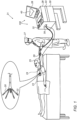
- Fig. 1 is a schematic, pictorial illustration of a system 21 for electroanatomical (EA) mapping, in accordance with an embodiment of the present invention.
- Fig. 1 depicts a physician 27 using a Pentaray ® EA mapping catheter 29 to perform an EA mapping of a heart 23 of a patient 25.
- Catheter 29 comprises, at its distal end, one or more arms 20, which may be mechanically flexible, each of which is coupled with one or more electrodes 22.
- electrodes 22 acquire and/or inject unipolar and/or bipolar signals from and/or to the tissue of heart 23.
- a processor 28 in a console 30 receives these signals via an electrical interface 35, and uses information contained in these signals to construct an EA map 40 that processor 28 stores in a memory 33.
- processor 28 may display EA map 40 on a display 26.
- User controls 32 of a user interface 100 enable physician 27 to communicate with processor 28 and command editing and/or highlighting portions of EA map 40.
- Controls 32 may include, for example, a trackball and control knobs, as well as a keyboard.
- Other elements of user interface 100 may include touch screen functionality of display 26.
- a tracking system is used to track the respective locations of sensing electrodes 22, such that each of the signals may be associated with the location at which the signal was acquired.
- ACL Active Catheter Location
- a processor estimates the respective locations of the electrodes based on impedances measured between each of the sensing electrodes 22, and a plurality of surface electrodes 24, that are coupled to the skin of patient 25. For example, three surface electrodes 24 may be coupled to the patient's chest, and another three surface electrodes may be coupled to the patient's back.
- Electric currents are passed between electrodes 22 inside heart 23 of the patient and surface electrodes 24.
- Processor 28 calculates an estimated location of all electrodes 22 within the patient's heart based on the ratios between the resulting current amplitudes measured at surface electrodes 24 (or between the impedances implied by these amplitudes) and the known locations of electrodes 24 on the patient's body.
- the processor may thus associate any given impedance signal received from electrodes 22 with the location at which the signal was acquired.
- Fig. 1 The example illustration shown in Fig. 1 is chosen purely for the sake of conceptual clarity. Other tracking methods can be used, such as those based on measuring voltage signals. Other types of sensing catheters, such as the Lasso ® Catheter (produced by Biosense Webster) or a basket catheter may equivalently be employed. Contact sensors may be fitted at the distal end of EA mapping catheter 29. As noted above, other types of electrodes, such as those used for ablation, may be utilized in a similar way and fitted to electrodes 22 for acquiring the needed location data. Thus, an ablation electrode used for collecting location data is regarded, in this case, as a sensing electrode. In an optional embodiment, processor 28 is further configured to indicate the quality of physical contact between each of the electrodes 22 and an inner surface of the cardiac chamber during measurement.
- processor 28 is further configured to indicate the quality of physical contact between each of the electrodes 22 and an inner surface of the cardiac chamber during measurement.
- Processor 28 typically comprises a general-purpose computer with software programmed to carry out the functions described herein.
- processor 28 runs a dedicated algorithm as disclosed herein, including in Fig. 3 , that enables processor 28 to perform the disclosed steps, as further described below.
- the software may be downloaded to the computer in electronic form, over a network, for example, or it may, alternatively or additionally, be provided and/or stored on non-transitory tangible media, such as magnetic, optical, or electronic memory.
- Fig. 2 is a volume-rendered semi-transparent EA map 200 of a left atrium showing locations marked for ablation (202) and respective projected locations 204 on a surface of the EA map, in accordance with an embodiment of the present invention.
- Fig. 2 shows a map for clarity and simplicity of presentation only. The disclosed process does not necessarily require generating such an initial map. Rather, acquisition data comprising locations is received in a processor, and the processor applies the disclosed steps to the mapped volume.
- mapped locations marked for ablation 202 are each along a circumference of an ostium 222 of a pulmonary vein.
- the mapped location may define a contour (not shown) along which a subsequent ablation is performed to isolate an arrhythmia.
- errors in map 200 may cause icons of locations 202 to be hidden in a non-transparent view.
- the processor identifies only locations 202 marked for treatment that fall in an interior of the mapped volume by determining if a vector between each location 202 marked for treatment and its respective projected surface location 204 is opposing an outward-pointing normal to the surface of the cavity at the projected location. Subsequently, the processor projects locations 202 to surface locations 204, in order to subsequently generate a map in which icons of locations 202 are visible, as described below.
- the processor projects all points marked for treatment, without attempting to identify which of the locations is internal. If a point is already on the surface, then the rolled ball diameter, or local volume to remove, will be zero or negligible.
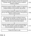
- Fig. 3 is a flow chart that schematically illustrates a method for exposing locations of a cardiac cavity marked for ablation, in accordance with an embodiment of the present invention.
- the algorithm carries out a process that begins with processor 28 receiving an EA map of at least a portion of a volume of a cardiac chamber, and a point cloud of locations marked for ablation, at a data receiving step 302. At this stage some of the location marked for ablation may comprise hidden icons.
- processor 28 projects the locations marked for ablation to respective locations on a surface of the chamber map volume, at a data projection step 304.
- processor 28 joins locations marked for ablation by a first spline, and joins the respective projected locations found in step 304 by a second spline.
- processor 28 generates an updated volume by automatically removing portions of the volume that comprise a surface connecting the locations marked for ablation with the projected locations. For example, the processor "rolls" a ball having a variable diameter (or “rolls” the aforementioned ellipsoid) along the two splines and removes from the chamber map volume the intersection between the chamber volume and the rolled ball, or ellipsoid.
- processor 28 uses the updated mapped data, or chamber volume map, processor 28 generates an EA map, such as map 440 shown below in Fig. 4B , of the portion of the cardiac cavity comprising visible icons that mark ablation locations.
- processor 28 presents the EA map to a user.
- the cavity is of an organ other than a heart.
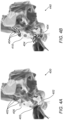
- Figs. 4A and 4B are volume-rendered non-transparent EA maps 400 and 440 of a cardiac cavity showing, respectively, a surface 405 that hides (402) icons of locations for ablation, and the mesh reshaped surface with the icons (404) exposed at locations marked for ablation, in accordance with embodiments of the present invention.
- Fig. 4A As seen in Fig. 4A , almost all the icons marking locations 402 for ablation on two ostia of a pulmonary vein of a left atrium are hidden under surface 405.
- Fig. 4B the regenerated surface 410 exposes respective locations, as shown by icons 404.
- a physician may use map 440 to perform the required ablation.
Landscapes
- Health & Medical Sciences (AREA)
- Life Sciences & Earth Sciences (AREA)
- Engineering & Computer Science (AREA)
- Surgery (AREA)
- Medical Informatics (AREA)
- Public Health (AREA)
- General Health & Medical Sciences (AREA)
- Biomedical Technology (AREA)
- Physics & Mathematics (AREA)
- Heart & Thoracic Surgery (AREA)
- Molecular Biology (AREA)
- Animal Behavior & Ethology (AREA)
- Veterinary Medicine (AREA)
- Pathology (AREA)
- Biophysics (AREA)
- Cardiology (AREA)
- Nuclear Medicine, Radiotherapy & Molecular Imaging (AREA)
- Physiology (AREA)
- General Physics & Mathematics (AREA)
- Primary Health Care (AREA)
- Theoretical Computer Science (AREA)
- Computer Graphics (AREA)
- Epidemiology (AREA)
- Plasma & Fusion (AREA)
- Otolaryngology (AREA)
- Radiology & Medical Imaging (AREA)
- Urology & Nephrology (AREA)
- General Engineering & Computer Science (AREA)
- Databases & Information Systems (AREA)
- Robotics (AREA)
- Data Mining & Analysis (AREA)
- Software Systems (AREA)
- Computer Hardware Design (AREA)
- Neurology (AREA)
- Oral & Maxillofacial Surgery (AREA)
- Surgical Instruments (AREA)
- Image Generation (AREA)
- Measuring And Recording Apparatus For Diagnosis (AREA)
- Magnetic Resonance Imaging Apparatus (AREA)
- Measurement And Recording Of Electrical Phenomena And Electrical Characteristics Of The Living Body (AREA)
Claims (19)
- Verfahren zum Freilegen versteckter Landmarken von Positionen zur Behandlung in einer anatomischen Karte, umfassend:Empfangen oder Generieren einer Volumenkarte von wenigstens einem Teil einer Kavität eines Organs eines Körpers, umfassend mehrere kartierte Positionen, und einer Punktwolke von Positionen in der Kavität, die zur Behandlung markiert sind;Aktualisieren der Volumenkarte durch Entfernen eines Teils der kartierten Positionen, sodass die zur Behandlung markierten Positionen auf eine Oberfläche der Volumenkarte fallen;Verwenden der aktualisierten Volumenkarte, wobei eine Karte von wenigstens einem Teil der Kavität generiert wird, umfassend die zur Behandlung markierten Positionen; undAnzeigen der Karte für einen Benutzer.
- Verfahren gemäß Anspruch 1, wobei das Entfernen des Teils der kartierten Positionen das Identifizieren einer oder mehrerer der zur Behandlung markierten Positionen umfasst, die in ein Inneres der Volumenkarte fallen, und Entfernen des Teils, sodass die identifizierten zur Behandlung markierten Positionen auf die Oberfläche der Volumenkarte fallen.
- Verfahren gemäß Anspruch 2, wobei das Identifizieren einer zur Behandlung markierten Position, die in das Innere der Volumenkarte fällt, das Bestimmen umfasst, dass ein Vektor, von der zur Behandlung markierten Position zu einer jeweiligen projizierten Position auf der Oberfläche, einer nach außen weisenden Normalen zu der Oberfläche an der projizierten Position gegenüberliegt.
- Verfahren gemäß Anspruch 1, wobei das Entfernen des Teils der kartierten Positionen das Projizieren der zur Behandlung markierten Positionen auf jeweilige Positionen auf der Oberfläche der Volumenkarte umfasst und das Entfernen des Teils der Volumenkarte, der eine Oberfläche umfasst, welche die zur Behandlung markierten Positionen mit den projizierten Positionen verbindet.
- Verfahren gemäß Anspruch 4, wobei das Entfernen der Oberfläche, welche die zur Behandlung markierten Positionen mit den projizierten Positionen verbindet, das Entfernen einer Oberfläche, die definiert ist als eine Oberfläche zwischen einer ersten Kurve, welche durch Verbinden der zur Behandlung markierten Positionen generiert wird, und einer zweiten Kurve, welche durch Verbinden der projizierten Positionen generiert wird, umfasst.
- Verfahren gemäß Anspruch 1, wobei das Entfernen des Teils der Volumenkarte das Definieren, zwischen jeder zur Behandlung markierten Position und einer jeweiligen projizierten Position auf der Oberfläche, eines jeweiligen Abstands, der in die Oberfläche eingebettet ist, und das Definieren des entfernten Teils basierend auf dem Abstand umfasst.
- Verfahren gemäß Anspruch 6, wobei das Definieren des entfernten Teils der Volumenkarte das Definieren einer Kugel umfasst, die einen Durchmesser aufweist, welcher dem Abstand entspricht.
- Verfahren gemäß Anspruch 1, wobei das Anzeigen der Karte für den Benutzer das Präsentieren eines oder mehrerer Symbole an den zur Behandlung markierten Positionen umfasst.
- System zum Freilegen versteckter Landmarken von Positionen zur Behandlung in einer anatomischen Karte, umfassend:einen Speicher, der dafür ausgelegt ist, mehrere kartierte Positionen, die in einer Kavität eines Organs eines Körpers bezogen werden, und eine Punktwolke von Positionen in der zur Behandlung markierten Kavität zu speichern; undeinen Prozessor, der ausgelegt ist zum:Empfangen oder Generieren einer Volumenkarte von wenigstens einem Teil der Kavität, umfassend die mehreren kartierten Positionen;Aktualisieren der Volumenkarte durch Entfernen eines Teils der kartierten Positionen, sodass die zur Behandlung markierten Positionen auf eine Oberfläche der Volumenkarte fallen;Verwenden der aktualisierten Volumenkarte, um eine Karte von wenigstens einem Teil der Kavität zu generieren, umfassend die zur Behandlung markierten Positionen; und Anzeigen der Karte für einen Benutzer.
- System gemäß Anspruch 9, wobei der Prozessor dafür ausgelegt ist, eine oder mehrere der zur Behandlung markierten Positionen zu identifizieren, die in ein Inneres der Volumenkarte fallen, und dafür, den Teil zu entfernen, sodass die identifizierten zur Behandlung markierten Positionen auf die Oberfläche der Volumenkarte fallen.
- System gemäß Anspruch 10, wobei der Prozessor dafür ausgelegt ist, eine zur Behandlung markierte Position zu identifizieren, die in das Innere der Volumenkarte fällt, indem bestimmt wird, dass ein Vektor, von der zur Behandlung markierten Position zu einer jeweiligen projizierten Position auf der Oberfläche, einer nach außen weisenden Normalen zu der Oberfläche an der projizierten Position gegenüberliegt.
- Verfahren gemäß Anspruch 1 oder das System gemäß Anspruch 9, wobei die zur Behandlung markierten Positionen Positionen auf einem Herzwandgewebe sind und zur Ablation markiert sind.
- Verfahren gemäß Anspruch 12, wobei das Generieren der Karte das Generieren einer elektroanatomischen (EA) Karte von wenigstens einem Teil des Herzwandgewebes umfasst.
- System gemäß Anspruch 12, wobei der Prozessor dafür ausgelegt ist, die Karte zu generieren, indem eine elektroanatomische (EA) Karte von wenigstens einem Teil des Herzwandgewebes generiert wird.
- System gemäß Anspruch 9, wobei der Prozessor dafür ausgelegt ist, die zur Behandlung markierten Positionen auf jeweilige Positionen auf der Oberfläche der Volumenkarte zu projizieren und den Teil der Volumenkarte, der eine Oberfläche umfasst, welche die zur Behandlung markierten Positionen mit den projizierten Positionen verbindet, zu entfernen.
- System gemäß Anspruch 15, wobei der Prozessor dafür ausgelegt ist, die Oberfläche zu entfernen, welche die zur Behandlung markierten Positionen mit den projizierten Positionen verbindet, indem eine Oberfläche, die definiert ist als eine Oberfläche zwischen einer ersten Kurve, welche durch Verbinden der zur Behandlung markierten Positionen generiert wird, und einer zweiten Kurve, welche durch Verbinden der projizierten Positionen generiert wird, entfernt wird.
- System gemäß Anspruch 9, wobei der Prozessor dafür ausgelegt ist, den Teil des Volumens zu entfernen, indem, zwischen jeder zur Behandlung markierten Position und einer jeweiligen projizierten Position auf der Oberfläche, ein jeweiliger Abstand, der in die Oberfläche eingebettet ist, definiert wird, und indem der entfernte Teil basierend auf dem Abstand definiert wird.
- System gemäß Anspruch 17, wobei der Prozessor dafür ausgelegt ist, den entfernten Teil der Volumenkarte zu definieren, indem eine Kugel definiert wird, die einen Durchmesser aufweist, welcher dem Abstand entspricht.
- System gemäß Anspruch 9, wobei der Prozessor dafür ausgelegt ist, die Karte für den Benutzer anzuzeigen, indem ein oder mehrere Symbole an den zur Behandlung markierten Positionen präsentiert werden.
Applications Claiming Priority (1)
| Application Number | Priority Date | Filing Date | Title |
|---|---|---|---|
| US17/151,825 US11911167B2 (en) | 2021-01-19 | 2021-01-19 | Automatic mesh reshaping of an anatomical map to expose internal points of interest |
Publications (3)
| Publication Number | Publication Date |
|---|---|
| EP4046574A1 EP4046574A1 (de) | 2022-08-24 |
| EP4046574B1 true EP4046574B1 (de) | 2023-09-27 |
| EP4046574C0 EP4046574C0 (de) | 2023-09-27 |
Family
ID=79730624
Family Applications (1)
| Application Number | Title | Priority Date | Filing Date |
|---|---|---|---|
| EP22151941.6A Active EP4046574B1 (de) | 2021-01-19 | 2022-01-18 | Automatische gitterumformung einer anatomischen karte zum freilegen von punkten von interesse |
Country Status (5)
| Country | Link |
|---|---|
| US (1) | US11911167B2 (de) |
| EP (1) | EP4046574B1 (de) |
| JP (1) | JP2022111102A (de) |
| CN (1) | CN114795233A (de) |
| IL (1) | IL289707B2 (de) |
Families Citing this family (8)
| Publication number | Priority date | Publication date | Assignee | Title |
|---|---|---|---|---|
| EP3923847B1 (de) | 2019-02-14 | 2025-06-18 | Kardium Inc. | Katheternavigationssysteme |
| US20220225925A1 (en) * | 2021-01-19 | 2022-07-21 | Biosense Webster (Israel) Ltd. | Automatic shaving of an anatomical map during ablation to expose internal points of interest |
| US11911167B2 (en) | 2021-01-19 | 2024-02-27 | Biosense Webster (Israel) Ltd. | Automatic mesh reshaping of an anatomical map to expose internal points of interest |
| EP4457772A1 (de) * | 2021-12-28 | 2024-11-06 | Biosense Webster (Israel) Ltd. | Automatisches rasieren einer anatomischen karte während der ablation zur exposition von internen interessenpunkten |
| CN116129060B (zh) * | 2023-04-18 | 2023-06-23 | 心航路医学科技(广州)有限公司 | 心脏三维解剖模型构建方法和心脏三维标测系统 |
| US12446963B2 (en) * | 2023-05-31 | 2025-10-21 | Biosense Webster (Israel) Ltd. | Automatic projection of a cardiac chamber posterior wall ablation line |
| US12543995B2 (en) | 2023-07-28 | 2026-02-10 | Biosense Webster (Israel) Ltd. | Methods and systems for shaving an anatomical map |
| EP4670661A1 (de) * | 2024-06-29 | 2025-12-31 | Substrate HD | Computerimplementiertes herzchirurgieunterstützungsverfahren |
Family Cites Families (17)
| Publication number | Priority date | Publication date | Assignee | Title |
|---|---|---|---|---|
| JPH06111000A (ja) * | 1992-09-30 | 1994-04-22 | Fujitsu Ltd | 立体表示装置 |
| US5975893A (en) | 1997-06-20 | 1999-11-02 | Align Technology, Inc. | Method and system for incrementally moving teeth |
| US6226542B1 (en) * | 1998-07-24 | 2001-05-01 | Biosense, Inc. | Three-dimensional reconstruction of intrabody organs |
| US6301496B1 (en) * | 1998-07-24 | 2001-10-09 | Biosense, Inc. | Vector mapping of three-dimensionally reconstructed intrabody organs and method of display |
| US7538764B2 (en) | 2001-01-05 | 2009-05-26 | Interuniversitair Micro-Elektronica Centrum (Imec) | System and method to obtain surface structures of multi-dimensional objects, and to represent those surface structures for animation, transmission and display |
| US8494608B2 (en) | 2008-04-18 | 2013-07-23 | Medtronic, Inc. | Method and apparatus for mapping a structure |
| US8456182B2 (en) | 2008-09-30 | 2013-06-04 | Biosense Webster, Inc. | Current localization tracker |
| US20110160569A1 (en) * | 2009-12-31 | 2011-06-30 | Amit Cohen | system and method for real-time surface and volume mapping of anatomical structures |
| US20130050207A1 (en) * | 2011-08-24 | 2013-02-28 | General Electric Company | Method and system for navigating, segmenting, and extracting a three-dimensional image |
| WO2015142445A1 (en) * | 2014-03-21 | 2015-09-24 | St. Jude Medical, Cardiology Division, Inc. | Methods and systems for generating a multi-dimensional surface model of a geometric structure |
| US10376320B2 (en) | 2016-05-11 | 2019-08-13 | Affera, Inc. | Anatomical model generation |
| CN106875462B (zh) * | 2017-01-13 | 2020-07-07 | 北京航空航天大学 | 一种基于元球模型和混合驱动方法的实时数字器官切割方法 |
| US11083517B2 (en) * | 2017-01-19 | 2021-08-10 | Biosense Webster (Israel) Ltd. | Enhancing efficiency of repeat ablation by merging current and previous maps |
| US11224392B2 (en) * | 2018-02-01 | 2022-01-18 | Covidien Lp | Mapping disease spread |
| JP7378427B2 (ja) * | 2019-05-03 | 2023-11-13 | コーニンクレッカ フィリップス エヌ ヴェ | 心臓画像の位置合わせ |
| US11113899B1 (en) | 2020-08-31 | 2021-09-07 | Biosense Webster (Israel) Ltd. | Correcting anatomical maps |
| US11911167B2 (en) | 2021-01-19 | 2024-02-27 | Biosense Webster (Israel) Ltd. | Automatic mesh reshaping of an anatomical map to expose internal points of interest |
-
2021
- 2021-01-19 US US17/151,825 patent/US11911167B2/en active Active
-
2022
- 2022-01-09 IL IL289707A patent/IL289707B2/en unknown
- 2022-01-18 EP EP22151941.6A patent/EP4046574B1/de active Active
- 2022-01-18 JP JP2022005504A patent/JP2022111102A/ja active Pending
- 2022-01-19 CN CN202210061354.1A patent/CN114795233A/zh active Pending
Also Published As
| Publication number | Publication date |
|---|---|
| US20220225924A1 (en) | 2022-07-21 |
| IL289707B2 (en) | 2025-01-01 |
| CN114795233A (zh) | 2022-07-29 |
| US11911167B2 (en) | 2024-02-27 |
| EP4046574A1 (de) | 2022-08-24 |
| JP2022111102A (ja) | 2022-07-29 |
| IL289707A (en) | 2022-08-01 |
| IL289707B1 (en) | 2024-09-01 |
| EP4046574C0 (de) | 2023-09-27 |
Similar Documents
| Publication | Publication Date | Title |
|---|---|---|
| EP4046574B1 (de) | Automatische gitterumformung einer anatomischen karte zum freilegen von punkten von interesse | |
| US20220225925A1 (en) | Automatic shaving of an anatomical map during ablation to expose internal points of interest | |
| CN1874735B (zh) | 对电生理导管的心脏应用提供可视化支持的方法和装置 | |
| US9668704B2 (en) | Method and device for visually assisting an electrophysiological use of a catheter in the heart | |
| JP7046591B2 (ja) | インタラクティブ方式の解剖学的マッピング及び解剖学的マッピングの品質の推定 | |
| JP7366535B2 (ja) | 食道に対する推定された心臓カテーテルの近接を表示するためのグラフィカルユーザーインターフェース(gui) | |
| JP7648083B2 (ja) | 表面更新制限を用いた高速解剖学的マッピング(fam)再構成 | |
| EP4457772A1 (de) | Automatisches rasieren einer anatomischen karte während der ablation zur exposition von internen interessenpunkten | |
| JP7366534B2 (ja) | 食道に対する心臓カテーテルの近接の推定 | |
| US11995849B2 (en) | Automatic registration of an anatomical map to a previous anatomical map | |
| US20250387065A1 (en) | Automatic storage and display of ecg signals indicative of atrial fibrillation | |
| AU2019219707A1 (en) | Post-mapping automatic identification of pulmonary veins | |
| US20240203079A1 (en) | Automatic editing of electroanatomical maps | |
| JP2024547075A (ja) | ユーザ臨床解釈に基づく電気生理学的(ep)マップポイント調整 | |
| EP4526848A1 (de) | Anzeige von orthografischen und endoskopischen ansichten einer in einem dreidimensionalen anatomischen bild ausgewählten ebene |
Legal Events
| Date | Code | Title | Description |
|---|---|---|---|
| PUAI | Public reference made under article 153(3) epc to a published international application that has entered the european phase |
Free format text: ORIGINAL CODE: 0009012 |
|
| STAA | Information on the status of an ep patent application or granted ep patent |
Free format text: STATUS: THE APPLICATION HAS BEEN PUBLISHED |
|
| AK | Designated contracting states |
Kind code of ref document: A1 Designated state(s): AL AT BE BG CH CY CZ DE DK EE ES FI FR GB GR HR HU IE IS IT LI LT LU LV MC MK MT NL NO PL PT RO RS SE SI SK SM TR |
|
| STAA | Information on the status of an ep patent application or granted ep patent |
Free format text: STATUS: REQUEST FOR EXAMINATION WAS MADE |
|
| 17P | Request for examination filed |
Effective date: 20230113 |
|
| RBV | Designated contracting states (corrected) |
Designated state(s): AL AT BE BG CH CY CZ DE DK EE ES FI FR GB GR HR HU IE IS IT LI LT LU LV MC MK MT NL NO PL PT RO RS SE SI SK SM TR |
|
| GRAP | Despatch of communication of intention to grant a patent |
Free format text: ORIGINAL CODE: EPIDOSNIGR1 |
|
| STAA | Information on the status of an ep patent application or granted ep patent |
Free format text: STATUS: GRANT OF PATENT IS INTENDED |
|
| RIC1 | Information provided on ipc code assigned before grant |
Ipc: A61B 5/343 20210101ALI20230331BHEP Ipc: A61B 5/367 20210101AFI20230331BHEP |
|
| INTG | Intention to grant announced |
Effective date: 20230421 |
|
| GRAS | Grant fee paid |
Free format text: ORIGINAL CODE: EPIDOSNIGR3 |
|
| GRAA | (expected) grant |
Free format text: ORIGINAL CODE: 0009210 |
|
| STAA | Information on the status of an ep patent application or granted ep patent |
Free format text: STATUS: THE PATENT HAS BEEN GRANTED |
|
| AK | Designated contracting states |
Kind code of ref document: B1 Designated state(s): AL AT BE BG CH CY CZ DE DK EE ES FI FR GB GR HR HU IE IS IT LI LT LU LV MC MK MT NL NO PL PT RO RS SE SI SK SM TR |
|
| REG | Reference to a national code |
Ref country code: GB Ref legal event code: FG4D |
|
| REG | Reference to a national code |
Ref country code: CH Ref legal event code: EP |
|
| REG | Reference to a national code |
Ref country code: DE Ref legal event code: R096 Ref document number: 602022000548 Country of ref document: DE |
|
| REG | Reference to a national code |
Ref country code: IE Ref legal event code: FG4D |
|
| U01 | Request for unitary effect filed |
Effective date: 20231024 |
|
| U07 | Unitary effect registered |
Designated state(s): AT BE BG DE DK EE FI FR IT LT LU LV MT NL PT SE SI Effective date: 20231030 |
|
| PG25 | Lapsed in a contracting state [announced via postgrant information from national office to epo] |
Ref country code: GR Free format text: LAPSE BECAUSE OF FAILURE TO SUBMIT A TRANSLATION OF THE DESCRIPTION OR TO PAY THE FEE WITHIN THE PRESCRIBED TIME-LIMIT Effective date: 20231228 |
|
| U20 | Renewal fee for the european patent with unitary effect paid |
Year of fee payment: 3 Effective date: 20231219 |
|
| PG25 | Lapsed in a contracting state [announced via postgrant information from national office to epo] |
Ref country code: RS Free format text: LAPSE BECAUSE OF FAILURE TO SUBMIT A TRANSLATION OF THE DESCRIPTION OR TO PAY THE FEE WITHIN THE PRESCRIBED TIME-LIMIT Effective date: 20230927 Ref country code: NO Free format text: LAPSE BECAUSE OF FAILURE TO SUBMIT A TRANSLATION OF THE DESCRIPTION OR TO PAY THE FEE WITHIN THE PRESCRIBED TIME-LIMIT Effective date: 20231227 Ref country code: HR Free format text: LAPSE BECAUSE OF FAILURE TO SUBMIT A TRANSLATION OF THE DESCRIPTION OR TO PAY THE FEE WITHIN THE PRESCRIBED TIME-LIMIT Effective date: 20230927 Ref country code: GR Free format text: LAPSE BECAUSE OF FAILURE TO SUBMIT A TRANSLATION OF THE DESCRIPTION OR TO PAY THE FEE WITHIN THE PRESCRIBED TIME-LIMIT Effective date: 20231228 |
|
| PG25 | Lapsed in a contracting state [announced via postgrant information from national office to epo] |
Ref country code: IS Free format text: LAPSE BECAUSE OF FAILURE TO SUBMIT A TRANSLATION OF THE DESCRIPTION OR TO PAY THE FEE WITHIN THE PRESCRIBED TIME-LIMIT Effective date: 20240127 |
|
| PG25 | Lapsed in a contracting state [announced via postgrant information from national office to epo] |
Ref country code: ES Free format text: LAPSE BECAUSE OF FAILURE TO SUBMIT A TRANSLATION OF THE DESCRIPTION OR TO PAY THE FEE WITHIN THE PRESCRIBED TIME-LIMIT Effective date: 20230927 |
|
| PG25 | Lapsed in a contracting state [announced via postgrant information from national office to epo] |
Ref country code: SM Free format text: LAPSE BECAUSE OF FAILURE TO SUBMIT A TRANSLATION OF THE DESCRIPTION OR TO PAY THE FEE WITHIN THE PRESCRIBED TIME-LIMIT Effective date: 20230927 Ref country code: RO Free format text: LAPSE BECAUSE OF FAILURE TO SUBMIT A TRANSLATION OF THE DESCRIPTION OR TO PAY THE FEE WITHIN THE PRESCRIBED TIME-LIMIT Effective date: 20230927 Ref country code: IS Free format text: LAPSE BECAUSE OF FAILURE TO SUBMIT A TRANSLATION OF THE DESCRIPTION OR TO PAY THE FEE WITHIN THE PRESCRIBED TIME-LIMIT Effective date: 20240127 Ref country code: ES Free format text: LAPSE BECAUSE OF FAILURE TO SUBMIT A TRANSLATION OF THE DESCRIPTION OR TO PAY THE FEE WITHIN THE PRESCRIBED TIME-LIMIT Effective date: 20230927 Ref country code: CZ Free format text: LAPSE BECAUSE OF FAILURE TO SUBMIT A TRANSLATION OF THE DESCRIPTION OR TO PAY THE FEE WITHIN THE PRESCRIBED TIME-LIMIT Effective date: 20230927 Ref country code: SK Free format text: LAPSE BECAUSE OF FAILURE TO SUBMIT A TRANSLATION OF THE DESCRIPTION OR TO PAY THE FEE WITHIN THE PRESCRIBED TIME-LIMIT Effective date: 20230927 |
|
| PG25 | Lapsed in a contracting state [announced via postgrant information from national office to epo] |
Ref country code: PL Free format text: LAPSE BECAUSE OF FAILURE TO SUBMIT A TRANSLATION OF THE DESCRIPTION OR TO PAY THE FEE WITHIN THE PRESCRIBED TIME-LIMIT Effective date: 20230927 |
|
| REG | Reference to a national code |
Ref country code: DE Ref legal event code: R097 Ref document number: 602022000548 Country of ref document: DE |
|
| PLBE | No opposition filed within time limit |
Free format text: ORIGINAL CODE: 0009261 |
|
| STAA | Information on the status of an ep patent application or granted ep patent |
Free format text: STATUS: NO OPPOSITION FILED WITHIN TIME LIMIT |
|
| PG25 | Lapsed in a contracting state [announced via postgrant information from national office to epo] |
Ref country code: MC Free format text: LAPSE BECAUSE OF FAILURE TO SUBMIT A TRANSLATION OF THE DESCRIPTION OR TO PAY THE FEE WITHIN THE PRESCRIBED TIME-LIMIT Effective date: 20230927 |
|
| PG25 | Lapsed in a contracting state [announced via postgrant information from national office to epo] |
Ref country code: MC Free format text: LAPSE BECAUSE OF FAILURE TO SUBMIT A TRANSLATION OF THE DESCRIPTION OR TO PAY THE FEE WITHIN THE PRESCRIBED TIME-LIMIT Effective date: 20230927 |
|
| 26N | No opposition filed |
Effective date: 20240628 |
|
| U20 | Renewal fee for the european patent with unitary effect paid |
Year of fee payment: 4 Effective date: 20241205 |
|
| PG25 | Lapsed in a contracting state [announced via postgrant information from national office to epo] |
Ref country code: IE Free format text: LAPSE BECAUSE OF NON-PAYMENT OF DUE FEES Effective date: 20240118 |
|
| PG25 | Lapsed in a contracting state [announced via postgrant information from national office to epo] |
Ref country code: IE Free format text: LAPSE BECAUSE OF NON-PAYMENT OF DUE FEES Effective date: 20240118 |
|
| PG25 | Lapsed in a contracting state [announced via postgrant information from national office to epo] |
Ref country code: CY Free format text: LAPSE BECAUSE OF FAILURE TO SUBMIT A TRANSLATION OF THE DESCRIPTION OR TO PAY THE FEE WITHIN THE PRESCRIBED TIME-LIMIT; INVALID AB INITIO Effective date: 20220118 |
|
| REG | Reference to a national code |
Ref country code: CH Ref legal event code: PL |
|
| PG25 | Lapsed in a contracting state [announced via postgrant information from national office to epo] |
Ref country code: CH Free format text: LAPSE BECAUSE OF NON-PAYMENT OF DUE FEES Effective date: 20250131 |
|
| PG25 | Lapsed in a contracting state [announced via postgrant information from national office to epo] |
Ref country code: TR Free format text: LAPSE BECAUSE OF FAILURE TO SUBMIT A TRANSLATION OF THE DESCRIPTION OR TO PAY THE FEE WITHIN THE PRESCRIBED TIME-LIMIT Effective date: 20230927 |
|
| PGFP | Annual fee paid to national office [announced via postgrant information from national office to epo] |
Ref country code: GB Payment date: 20251204 Year of fee payment: 5 |
|
| U20 | Renewal fee for the european patent with unitary effect paid |
Year of fee payment: 5 Effective date: 20251205 |