EP4046477B1 - Pflanzbehälter zur begrünung von wänden - Google Patents
Pflanzbehälter zur begrünung von wänden Download PDFInfo
- Publication number
- EP4046477B1 EP4046477B1 EP21461517.1A EP21461517A EP4046477B1 EP 4046477 B1 EP4046477 B1 EP 4046477B1 EP 21461517 A EP21461517 A EP 21461517A EP 4046477 B1 EP4046477 B1 EP 4046477B1
- Authority
- EP
- European Patent Office
- Prior art keywords
- wall
- draining pipe
- main body
- plant container
- previous
- Prior art date
- Legal status (The legal status is an assumption and is not a legal conclusion. Google has not performed a legal analysis and makes no representation as to the accuracy of the status listed.)
- Active
Links
Images


Classifications
-
- A—HUMAN NECESSITIES
- A01—AGRICULTURE; FORESTRY; ANIMAL HUSBANDRY; HUNTING; TRAPPING; FISHING
- A01G—HORTICULTURE; CULTIVATION OF VEGETABLES, FLOWERS, RICE, FRUIT, VINES, HOPS OR SEAWEED; FORESTRY; WATERING
- A01G9/00—Cultivation in receptacles, forcing-frames or greenhouses; Edging for beds, lawn or the like
- A01G9/02—Receptacles, e.g. flower-pots or boxes; Glasses for cultivating flowers
- A01G9/022—Pots for vertical horticulture
- A01G9/025—Containers and elements for greening walls
-
- A—HUMAN NECESSITIES
- A01—AGRICULTURE; FORESTRY; ANIMAL HUSBANDRY; HUNTING; TRAPPING; FISHING
- A01G—HORTICULTURE; CULTIVATION OF VEGETABLES, FLOWERS, RICE, FRUIT, VINES, HOPS OR SEAWEED; FORESTRY; WATERING
- A01G27/00—Self-acting watering devices, e.g. for flower-pots
- A01G27/005—Reservoirs connected to flower-pots through conduits
-
- Y—GENERAL TAGGING OF NEW TECHNOLOGICAL DEVELOPMENTS; GENERAL TAGGING OF CROSS-SECTIONAL TECHNOLOGIES SPANNING OVER SEVERAL SECTIONS OF THE IPC; TECHNICAL SUBJECTS COVERED BY FORMER USPC CROSS-REFERENCE ART COLLECTIONS [XRACs] AND DIGESTS
- Y02—TECHNOLOGIES OR APPLICATIONS FOR MITIGATION OR ADAPTATION AGAINST CLIMATE CHANGE
- Y02P—CLIMATE CHANGE MITIGATION TECHNOLOGIES IN THE PRODUCTION OR PROCESSING OF GOODS
- Y02P60/00—Technologies relating to agriculture, livestock or agroalimentary industries
- Y02P60/20—Reduction of greenhouse gas [GHG] emissions in agriculture, e.g. CO2
Definitions
- the present invention relates to plant containers for greening walls.
- a greening wall is a vertical structure that comprises containers with green plants.
- the containers are provided as a support for growth medium, such as soil or substitute substrate, in which individual plants may grow.
- growth medium such as soil or substitute substrate
- the greening wall is provided with an irrigation system that supplies water to individual containers.
- a British patent application GB2482482A discloses a plant holder having a chamber for holding soil and plants and a reservoir located within the chamber and provided with holes for the egress of water from the reservoir and into the chamber to irrigate the soil and plants. Water is added to the reservoir so as to seep through the perforations and irrigate the soil. The discharge rate of the water depends on the size of the perforations and also the water pressure which is governed by the dimensions of the reservoir. All the water that is supplied to the reservoir will be discharged to the soil. The plant holder does contain any means for draining excess water, therefore there is a risk of excessive watering of the plant.
- a Chinese patent application CN105850555A discloses a greening box comprising a box body having a bottom plate and a plurality of side panels arranged on the bottom plate.
- the bottom plate is provided with a drainage structure having a form of one or more drainage columns disposed on the bottom plate, wherein the drainage column is vertically penetrated inside and the bottom portion thereof penetrates the bottom plate.
- a hollow cylinder is disposed on the inner side wall of the rear side panel and has a through hole therein for connecting the boxes located next to each other by means of a U-shaped rod that is put into that cylinder.
- a Chinese patent application CN103243739A discloses a reinforced retaining wall ecological panel structure with a self-interlocking function.
- the wall comprises open hollow prefabricated blocks which are stacked.
- the prefabricated block is provided with a reserved hole penetrating the prefabricated block vertically, into which a connecting piece can be inserted to connect the upper and lower prefabricated blocks.
- the bottom surface of the prefabricated block is provided with a drainage hole.
- a US patent application US2013152467 discloses a planter device that includes an upper planter pot and a lower planter pot attached to a supporting device, the planter pots each include a port coupled to a tube, the upper planter pot includes an outlet conduit coupled to the tube of the lower planter pot, a water supplying pipe is connected to a coupler for supplying a water to the tube and the port of the upper planter pot.
- the coupler includes a bore for supplying the water from the water supplying pipe to the tube, and includes an outlet channel communicative with the bore of the coupler for supplying the water out of the coupler and into the upper planter pot.
- CN107343468A discloses a building planting wall structure with a plurality of base plates. At least one drainage passage is disposed in the base plates. Tops and bottoms of the base plates are provided with water discharging covers and water feeding cork covers respectively. Positions near the top and bottom of the drainage pipe disposed at the inside rear part of each planting pot are provided with a plurality of water holes.
- Drainage holes located at the bottom wall have a disadvantage such that when a plurality of containers are arranged in a column over each other, the lowest-located container will receive excess water from all containers located above it and consequently the soil therein may be watered excessively.
- the dripping water may contain particles of soil that may stain the plants at which it drips.
- the dripping water may flow over the leaves of the plant outside the container, which poses a risk of flooding the floor below the green wall. Therefore, the amount of water delivered to each container must be precisely controlled (which is difficult) , and shall depend on the position of the container at the greening wall (i.e. the amount of water to be delivered to the containers positioned below other containers shall take into account the amount of water that will drip from the containers above it).
- the invention concerns plant container for greening walls and a greening wall comprising a plurality of such plant containers, according to the appended claims.
- the container for greening walls comprises a main body defining a chamber for receiving a growth medium for a plant.
- a draining pipe is coupled with the main body, extends along a back wall of the main body and has a top end, a bottom end and an opening in its wall for allowing water from inside the chamber to enter inside the draining pipe.
- a connecting conduit is provided and configured to connect the bottom end of the draining pipe with a top end of a draining pipe of another plant container of the same type. Thereby, the draining pipe can collect water from within the chamber of the container and the collected water can be transferred, via the connecting conduit, to the draining pipe of another plant container. This allows to build a greening wall with a plurality of containers located one above each other, such that water from their chambers is collected into the draining pipes and can flow through the draining pipes towards the bottom of the greening wall.
- the connecting conduit of the bottom-most container of the greening wall can be connected to a reservoir for collecting the excess water drained from all the containers above it. Since each draining pipe has its top end positioned above its bottom end, water flows under the force of gravity along the internal walls of the draining pipes to the collecting reservoir at the bottom of the greening wall rather than outside the draining pipe to the chambers of lower-positioned containers. Thereby, excess water is efficiently removed from the container and the drained water does not impact the containers located below. Consequently, each container can be watered independently of other containers. Moreover, the containers do not accumulate water from other containers.
- the draining pipe can extend vertically along the main body. This facilitates water flow downwards the draining pipe.
- the draining pipe is inclined or curved.
- its wall shall be inclined downwards along its whole length.
- the draining pipe can be formed integrally with the back wall, i.e. such that the back wall of the container forms the back wall of the draining pipe.
- the top end of the draining pipe is preferably located along the vertical line above the bottom end, which makes it easy to connect the draining pipes of successive containers in a vertical column.
- the connecting conduit can be formed integrally with the container, i.e. it can be formed of the same material as the container at a position adjacent to the bottom end of the draining pipe and have a form of a pipe that has at its end an external diameter not larger than the internal diameter of the top end of the draining pipe, such that the connecting conduit can be inserted to the draining pipe of another container.
- This facilitates water-tightness of the connection, namely in such a case the connecting conduit does not have to fit tightly into the lower draining pipe, as water will flow downwards under the force of gravity.
- Other forms of the connecting conduit are possible as well, such as various types of rigid or elastic pipes configured to be fit between the opposite ends of the draining pipes.
- the opening in the wall of the draining pipe is a slit that extends along the whole length of the draining pipe. This is particularly preferable when the draining pipe is vertical, as such construction allows manufacturing of the container in an injection molding process as a single piece that does not have to be subject to further machining operations to make it operative. Moreover, a long slit facilitates collection of excess water from the chamber to the draining pipe.
- the opening may be positioned at one side of the draining pipe (e.g. at the side or at the front), it may be also located at different sides.
- the container may comprise an insert configured to be installed at a bottom end of the draining pipe to cover at least part of the opening.
- the insert may obscure the slit at the bottom.
- the insert may allow to define a volume at the bottom of the chamber in which water is collected rather than being drained out of the chamber. Therefore, the greening wall may comprise a plurality of containers of a default type with the drain pipes with openings defined at the very bottom of the main body, and each container may have an insert installed that has a height selected according to the hydration needs of a particular plant that is to be installed in that container.
- the container may have fasteners at a back wall of the main body, suitable for securing the main body to a greening wall structure.
- the fasteners are hooks at the top edge of the back wall, by means of which the container may be hanged on the greening wall structure elements. It is particularly preferable if the hooks are positioned asymmetrically off-centre, such that a two containers can be hanged on a horizontal bar of the greening wall structure at the opposite sides of that wall and not interfere with each other.
- At least one rib may extend along the internal portion of at least one wall - of the main body.
- the rib may extend from a top (or from close to the top, such as 10% of the wall height from the top edge) to a bottom (or to close to the bottom, such as 10% of the wall height from the bottom) of the side wall, the front wall and/or the back wall, or from front to the back of the bottom wall.
- the rib may be thin, i.e. it may have a height (measured as an extent by which it protrudes from the wall towards the chamber) greater than its width.
- the rib forms a straight section along the wall (which makes it easy to manufacture), but it may also have other forms, such as curved, inclined or horizontal ones.
- the ribs of the bottom wall form a continuation of the ribs of the side walls, the front wall or the back wall. If the growth medium is packed in an elastic pouch and inserted into the container, the rib allows to move the pouch away from the internal wall of the container, thereby allowing air to circulate around the pouch.
- a plurality of ribs may be arranged in pairs or more multiples thereof, wherein the pair comprises two ribs parallel and close to each other (e.g. not farther than twice their height from each other), which forms an air channel between the ribs such that air can easily circulate between the wall and the pouch even if the pouch is quite loose.
- the draining pipe may have the opening in a form of a longitudinal slit located at a side of the draining pipe (i.e. facing one of the side walls) and a rib may be formed at the back wall close to the opening (i.e. at a distance not exceeding twice the height of the rib), such that an air channel can be formed between the back wall and the slit and the pouch with the growing medium, which facilitates water drainage from the pouch to the opening of the draining pipe and prevents clogging of the opening and facilitates air access to the pouch.
- the pouch with the growth medium that can be located within the chamber is preferably made of an elastic material, such as a textile fabric or non-woven fabric, having parameters that allow water and air to penetrate its surface so that water and air can get in and out of the pouch.
- an elastic material such as a textile fabric or non-woven fabric
- the chamber may be configured to receive a plurality (i.e. two, three or more) of pouches positioned next to each other.
- the container may have a single drain pipe located centrally between the pouch inserting sites to receive water draining from all pouches or a plurality of drain pipes, each located at a position at which the pouch is to be inserted.
- the pouch inserting sites can be defined by a curvature of the front wall which may be shaped as to come closer to the back wall at a place between the pouch inserting sites, such as to hold the pouches in predetermined places.
- the plant container may further comprise a recess in each of the side walls, for accommodating a horizontal water supply pipe which may extend along a row of containers positioned at the same level.
- the horizontal water supply pipe may contain at least one dripper located above each container such as to deliver water at a certain amount to the container.
- the horizontal water supply pipes may be connected to a vertical water supply line.
- the container is preferably made of a rigid material, such as plastic. However, other materials can be used as well, such as steel if special functional or aesthetic properties are desirable.
- a plastic container can be formed in an injection molding process or in a 3D printing process. It can be made as a single-piece element or assembled from a plurality of elements.
- the walls of the main body do not need to have a uniform flat form. They may be curved, round or oblique.
- the terms a back wall, a side wall, a bottom wall and a front wall refer to portions of the container that are substantially facing the back, side, bottom or front of the container.
- the edge sections of the walls may be straight (in particular, between the side walls and the back wall) or curved (in particular, between the side walls and the front wall or between the bottom wall and the front wall).
- the side walls and the front wall may have their top edges positioned lower than the top edge of the back wall in order to allow mounting of containers one above each other with their back walls adjacent, and having some free space at the front to allow the plant to extend over the edges of the front wall.
- the invention also relates to a greening wall comprising a plurality of containers as described herein mounted on a frame.
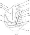
- Figs. 1-5 show a first embodiment of the invention which is a plant container for a single pouch.
- the container has a main body 100 comprising a back wall 101, two side walls 102, 103, a bottom wall 104 and a front wall 105.
- the walls 101-105 encompass a chamber 110 in which a growth medium 112 for a plant (and preferably with the plant 113) can be positioned.
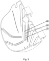
- a draining pipe 120 is coupled with the main body 100 such that it is integrated with the back wall 101, wherein the back wall 101 of the main body 100 forms the back wall of the draining pipe 120.
- the draining pipe 120 has a top end 121 positioned vertically above a bottom end 122, and a connecting conduit 124 located adjacently to the bottom end 122.
- the connecting conduit 124 has a diameter smaller than the internal diameter of the top end 121 of the draining pipe 120, therefore it can be easily inserted into the draining pipe 120 of a container of the same type located below, as shown in Fig. 5 .
- an insert 125 can be installed at a bottom end 122 of the draining pipe 120 to cover a bottom portion of the opening slit 123, such that some water can be collected at the bottom of the container up to the height of the insert 125, depending on the needs of the plant growing in that container.
- a pair of off-centered hooks 106 is formed at the back wall 101 of the main body 100, by means of which the container may be hang on a greening wall structure, such as shown in Fig. 8 , wherein two containers are hang at opposite sides of a horizontal bar 201 of the structure.
- a plurality of pairs of ribs 107 extend along all walls 101-105, which offset the pouch 111 with the growth medium 112 from the walls, as shown in Fig. 4 .
- one of the ribs 107A is located at a distance not exceeding twice its height, from the slit 123 formed at a side wall of the draining pipe 120.
- Fig. 6 shows a second embodiment of the container, which is similar to the first embodiment, with the following differences.
- the front wall 105 is curved, such that two sections 110A, 110B are defined within the chamber that allow to position two pouches therein.
- a single central drain pipe 120 preferably having the opening 123 facing the front wall 105, is present for collecting water from pouches located in both sections 110A, 110B, thereby the container can be used with the same type of the container or the type of the first embodiment, located above or below it.
- This type of container can be fastened to the greening wall structure by means of hooks as in the first embodiment or by screws inserted to attachment openings 109.
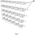
- Fig. 7 shows a greening wall formed from a plurality of plant containers of the first embodiment mounted on a frame 200.
- Fig. 9 shows a portion of a greening wall formed from a plurality of plant containers of the second embodiment, with water supply pipes 211 with drippers 212 extend along each row of containers positioned at the same level.
- the horizontal water supply pipes 211 may be connected to common vertical water supply line 213.
Landscapes
- Life Sciences & Earth Sciences (AREA)
- Environmental Sciences (AREA)
- Engineering & Computer Science (AREA)
- Water Supply & Treatment (AREA)
- Cultivation Receptacles Or Flower-Pots, Or Pots For Seedlings (AREA)
Claims (11)
- Pflanzgefäß für Begrünungswände, umfassend:- einen Hauptkörper (100), der eine Kammer (110) zur Aufnahme eines Wachstumsmediums für eine Pflanze definiert;- ein Abflussrohr (120), das mit dem Hauptkörper (100) gekoppelt ist, sich entlang einer Rückwand (101) des Hauptkörpers (100) erstreckt und ein oberes Ende (121), ein unteres Ende (122) und eine Öffnung (123) in seiner Wand aufweist, damit Wasser aus dem Inneren der Kammer (110) in das Abflussrohr (120) einfließen kann; und- eine Verbindungsleitung (124), die dazu konfiguriert ist, das untere Ende (122) des Abflussrohrs (120) mit einem oberen Ende (121) eines Abflussrohrs (120) eines anderen Pflanzgefäßes desselben Typs zu verbinden;dadurch gekennzeichnet, dass:- die Öffnung (123) in der Wand des Abflussrohrs (120) ein Schlitz ist, der sich von einem Boden des Hauptkörpers (100) entlang der gesamten Länge des Abflussrohrs erstreckt;das Abflussrohr (120) ein Durchgangsloch aufweist, das sich entlang der gesamten Länge des Abflussrohrs (120) von seinem oberen Ende (121) bis zu seinem unteren Ende (122) erstreckt.
- Pflanzgefäß nach Anspruch 1, wobei sich das Abflussrohr (120) vertikal entlang des Hauptkörpers (101) erstreckt.
- Pflanzgefäß nach einem der vorhergehenden Ansprüche, wobei das Abflussrohr (120) einstückig mit der Rückwand (101) des Hauptkörpers (100) ausgebildet ist.
- Pflanzgefäß nach einem der vorhergehenden Ansprüche, ferner umfassend einen Einsatz (125), der am unteren Ende (122) des Abflussrohrs (120) installiert ist, um zumindest einen Teil der Öffnung (123) abzudecken.
- Pflanzgefäß nach einem der vorhergehenden Ansprüche, ferner umfassend Befestigungselemente (106) an einer Rückwand (101) des Hauptkörpers (100) zum Befestigen des Hauptkörpers (100) an einer Begrünungswandstruktur.
- Pflanzgefäß nach einem der vorhergehenden Ansprüche, ferner umfassend mindestens eine Rippe (107), die sich entlang des Innenabschnitts mindestens einer Wand (101-105) des Hauptkörpers erstreckt.
- Pflanzgefäß nach einem der vorhergehenden Ansprüche, ferner umfassend ein Paar Rippen (107), die parallel zueinander sind und sich entlang des Innenabschnitts mindestens einer Wand (101-105) des Hauptkörpers erstrecken.
- Pflanzgefäß nach einem der vorhergehenden Ansprüche, ferner umfassend eine Aussparung (108) in jeder der Seitenwände (102, 103) zur Aufnahme eines Wasserversorgungsrohrs.
- Pflanzgefäß nach einem der vorhergehenden Ansprüche, ferner umfassend einen Beutel (111) mit dem Wachstumsmedium (112), der sich in der Kammer (110) befindet.
- Pflanzgefäß nach einem der vorhergehenden Ansprüche, wobei die Kammer (110) dazu konfiguriert ist, mehrere nebeneinander positionierte Beutel (111) aufzunehmen.
- Begrünungswand, umfassend mehrere Pflanzgefäße nach einem der vorhergehenden Ansprüche, die an einem Rahmen (200) montiert sind.
Priority Applications (3)
| Application Number | Priority Date | Filing Date | Title |
|---|---|---|---|
| EP21461517.1A EP4046477B1 (de) | 2021-02-19 | 2021-02-19 | Pflanzbehälter zur begrünung von wänden |
| PL21461517.1T PL4046477T3 (pl) | 2021-02-19 | 2021-02-19 | Pojemnik na rośliny do zielonych ścian |
| US17/670,657 US12507637B2 (en) | 2021-02-19 | 2022-02-14 | Plant container for greening walls and a greening wall |
Applications Claiming Priority (1)
| Application Number | Priority Date | Filing Date | Title |
|---|---|---|---|
| EP21461517.1A EP4046477B1 (de) | 2021-02-19 | 2021-02-19 | Pflanzbehälter zur begrünung von wänden |
Publications (3)
| Publication Number | Publication Date |
|---|---|
| EP4046477A1 EP4046477A1 (de) | 2022-08-24 |
| EP4046477C0 EP4046477C0 (de) | 2023-08-30 |
| EP4046477B1 true EP4046477B1 (de) | 2023-08-30 |
Family
ID=74673168
Family Applications (1)
| Application Number | Title | Priority Date | Filing Date |
|---|---|---|---|
| EP21461517.1A Active EP4046477B1 (de) | 2021-02-19 | 2021-02-19 | Pflanzbehälter zur begrünung von wänden |
Country Status (3)
| Country | Link |
|---|---|
| US (1) | US12507637B2 (de) |
| EP (1) | EP4046477B1 (de) |
| PL (1) | PL4046477T3 (de) |
Families Citing this family (4)
| Publication number | Priority date | Publication date | Assignee | Title |
|---|---|---|---|---|
| USD1034294S1 (en) * | 2021-03-02 | 2024-07-09 | 4Naturesystem—Wertykalni Sp. Z O.O. | Flowerpot |
| USD1023825S1 (en) * | 2021-03-02 | 2024-04-23 | 4Naturesystem—Wertykalni Sp. Z O.O. | Flowerpot |
| US20220304249A1 (en) * | 2021-03-29 | 2022-09-29 | Christopher Todd Wente | Modular ecological system for walls |
| USD1044322S1 (en) * | 2022-04-19 | 2024-10-01 | Jianfeng Ye | Flower pot |
Family Cites Families (16)
| Publication number | Priority date | Publication date | Assignee | Title |
|---|---|---|---|---|
| US8341884B2 (en) * | 2006-01-23 | 2013-01-01 | Quizcamp-Fabrico e Comércio de Produtos Alimentares, S.A. | Modular container system |
| JP5319498B2 (ja) * | 2009-11-10 | 2013-10-16 | サントリーホールディングス株式会社 | 植栽容器 |
| GB2482482B (en) | 2010-08-02 | 2015-12-23 | Useful And Practical Ideas Ltd | Plant holder |
| WO2012081945A2 (ko) * | 2010-12-16 | 2012-06-21 | Bae Moon Ok | 입체 녹화용 식물 재배 용기 및 이를 이용한 입체 녹화 시스템 |
| US8683744B2 (en) * | 2011-01-21 | 2014-04-01 | Hsiao-An Chang | Expandable flowerpot |
| CN202145768U (zh) * | 2011-07-14 | 2012-02-22 | 水伯格五金(深圳)有限公司 | 挂壁式花盆 |
| US20130152467A1 (en) | 2011-12-20 | 2013-06-20 | Cheng Chung Chang | Watering system for planter combination background of the invention |
| KR101247700B1 (ko) * | 2012-07-16 | 2013-03-26 | 주식회사 에코스타일 | 조경용 화분 |
| CN103243739A (zh) | 2013-05-15 | 2013-08-14 | 招商局重庆交通科研设计院有限公司 | 具有自嵌锁功能的加筋土挡墙生态面板结构 |
| DK177900B1 (en) * | 2013-10-07 | 2014-12-01 | Grønning Plantemiljø As | Wall Module System, a Method of cultivating plants, and Use of a wall module system for cultivating plants |
| TWM475807U (en) * | 2013-10-09 | 2014-04-11 | Sheng San Co Ltd | Planting pot combination structure featuring controllable water diversion |
| CN105386500A (zh) * | 2015-10-19 | 2016-03-09 | 梁恩銘 | 开孔渗灌排水管及密封全自动渗灌雨水回收全方位种植盆 |
| TWI577275B (zh) * | 2016-04-01 | 2017-04-11 | 林鼎堯 | Building wall structure |
| CN105850555A (zh) | 2016-04-15 | 2016-08-17 | 肖健雄 | 一种立体绿化盒 |
| WO2022086242A2 (ko) * | 2020-10-21 | 2022-04-28 | 주식회사 그린월 | 배수 유량 및 수위 조절이 가능한 화분 및 이를 위한 배수 구조 |
| KR102319860B1 (ko) * | 2020-10-21 | 2021-11-01 | 주식회사 그린월 | 배수 유량 및 수위 조절이 가능한 화분 및 이를 위한 배수 구조 |
-
2021
- 2021-02-19 PL PL21461517.1T patent/PL4046477T3/pl unknown
- 2021-02-19 EP EP21461517.1A patent/EP4046477B1/de active Active
-
2022
- 2022-02-14 US US17/670,657 patent/US12507637B2/en active Active
Also Published As
| Publication number | Publication date |
|---|---|
| EP4046477C0 (de) | 2023-08-30 |
| US20220264807A1 (en) | 2022-08-25 |
| PL4046477T3 (pl) | 2024-02-19 |
| EP4046477A1 (de) | 2022-08-24 |
| US12507637B2 (en) | 2025-12-30 |
Similar Documents
| Publication | Publication Date | Title |
|---|---|---|
| EP4046477B1 (de) | Pflanzbehälter zur begrünung von wänden | |
| CA2890953C (en) | Growth device for crop, use of such a device, and a series of growth devices | |
| EP3155892B1 (de) | Modularer behälter und modulares bewässerungssystem | |
| US20110258925A1 (en) | Vertical planter | |
| KR101232644B1 (ko) | 수경 재배용 베드 | |
| KR100869173B1 (ko) | 파티션 | |
| JP4564984B2 (ja) | 育苗装置 | |
| KR20140081651A (ko) | 저면관수용 포트 받침 | |
| KR20090002388U (ko) | 화분 받침대 | |
| KR102039379B1 (ko) | 식재가 용이한 저수조 멀티 화분 | |
| US20010052199A1 (en) | Stackable planter | |
| KR20090056752A (ko) | 안정된 급·배수구조가 마련된 적층식 화분 | |
| WO1989004600A1 (en) | Plant-growth trough for earthless growing of plants | |
| KR20100127144A (ko) | 모종 재배용 급수장치 | |
| KR101232643B1 (ko) | 수경 재배장치 | |
| JP4928992B2 (ja) | 底面潅水用給水パネル及び同パネル用の栽培ポット並びにそれらを用いた栽培システム | |
| KR101196121B1 (ko) | 식생 상자 조립체 | |
| GB2369980A (en) | A self watering tiered plant container | |
| KR101768684B1 (ko) | 수직형 수경재배기 | |
| EP3582606A1 (de) | Modul zur vertikalen begrünung, system zur vertikalen begrünung und verfahren zur herstellung eines moduls zur vertikalen begrünung | |
| JP2002153134A (ja) | 高設栽培容器 | |
| KR20170094524A (ko) | 수경재배기를 이용한 작물의 수직 재배방법 | |
| CN110139554A (zh) | 具有根屏障的植物种植系统 | |
| KR20250144701A (ko) | 수경재배기 | |
| KR20230174623A (ko) | 수위조절기구를 구비한 수경식물 재배기 |
Legal Events
| Date | Code | Title | Description |
|---|---|---|---|
| PUAI | Public reference made under article 153(3) epc to a published international application that has entered the european phase |
Free format text: ORIGINAL CODE: 0009012 |
|
| STAA | Information on the status of an ep patent application or granted ep patent |
Free format text: STATUS: THE APPLICATION HAS BEEN PUBLISHED |
|
| AK | Designated contracting states |
Kind code of ref document: A1 Designated state(s): AL AT BE BG CH CY CZ DE DK EE ES FI FR GB GR HR HU IE IS IT LI LT LU LV MC MK MT NL NO PL PT RO RS SE SI SK SM TR |
|
| STAA | Information on the status of an ep patent application or granted ep patent |
Free format text: STATUS: REQUEST FOR EXAMINATION WAS MADE |
|
| 17P | Request for examination filed |
Effective date: 20221017 |
|
| RBV | Designated contracting states (corrected) |
Designated state(s): AL AT BE BG CH CY CZ DE DK EE ES FI FR GB GR HR HU IE IS IT LI LT LU LV MC MK MT NL NO PL PT RO RS SE SI SK SM TR |
|
| GRAP | Despatch of communication of intention to grant a patent |
Free format text: ORIGINAL CODE: EPIDOSNIGR1 |
|
| STAA | Information on the status of an ep patent application or granted ep patent |
Free format text: STATUS: GRANT OF PATENT IS INTENDED |
|
| INTG | Intention to grant announced |
Effective date: 20230323 |
|
| GRAS | Grant fee paid |
Free format text: ORIGINAL CODE: EPIDOSNIGR3 |
|
| GRAA | (expected) grant |
Free format text: ORIGINAL CODE: 0009210 |
|
| STAA | Information on the status of an ep patent application or granted ep patent |
Free format text: STATUS: THE PATENT HAS BEEN GRANTED |
|
| AK | Designated contracting states |
Kind code of ref document: B1 Designated state(s): AL AT BE BG CH CY CZ DE DK EE ES FI FR GB GR HR HU IE IS IT LI LT LU LV MC MK MT NL NO PL PT RO RS SE SI SK SM TR |
|
| REG | Reference to a national code |
Ref country code: GB Ref legal event code: FG4D |
|
| REG | Reference to a national code |
Ref country code: CH Ref legal event code: EP |
|
| REG | Reference to a national code |
Ref country code: DE Ref legal event code: R096 Ref document number: 602021004739 Country of ref document: DE |
|
| REG | Reference to a national code |
Ref country code: IE Ref legal event code: FG4D |
|
| U01 | Request for unitary effect filed |
Effective date: 20231002 |
|
| U07 | Unitary effect registered |
Designated state(s): AT BE BG DE DK EE FI FR IT LT LU LV MT NL PT SE SI Effective date: 20231011 |
|
| PG25 | Lapsed in a contracting state [announced via postgrant information from national office to epo] |
Ref country code: GR Free format text: LAPSE BECAUSE OF FAILURE TO SUBMIT A TRANSLATION OF THE DESCRIPTION OR TO PAY THE FEE WITHIN THE PRESCRIBED TIME-LIMIT Effective date: 20231201 |
|
| PG25 | Lapsed in a contracting state [announced via postgrant information from national office to epo] |
Ref country code: IS Free format text: LAPSE BECAUSE OF FAILURE TO SUBMIT A TRANSLATION OF THE DESCRIPTION OR TO PAY THE FEE WITHIN THE PRESCRIBED TIME-LIMIT Effective date: 20231230 |
|
| PG25 | Lapsed in a contracting state [announced via postgrant information from national office to epo] |
Ref country code: RS Free format text: LAPSE BECAUSE OF FAILURE TO SUBMIT A TRANSLATION OF THE DESCRIPTION OR TO PAY THE FEE WITHIN THE PRESCRIBED TIME-LIMIT Effective date: 20230830 Ref country code: NO Free format text: LAPSE BECAUSE OF FAILURE TO SUBMIT A TRANSLATION OF THE DESCRIPTION OR TO PAY THE FEE WITHIN THE PRESCRIBED TIME-LIMIT Effective date: 20231130 Ref country code: IS Free format text: LAPSE BECAUSE OF FAILURE TO SUBMIT A TRANSLATION OF THE DESCRIPTION OR TO PAY THE FEE WITHIN THE PRESCRIBED TIME-LIMIT Effective date: 20231230 Ref country code: HR Free format text: LAPSE BECAUSE OF FAILURE TO SUBMIT A TRANSLATION OF THE DESCRIPTION OR TO PAY THE FEE WITHIN THE PRESCRIBED TIME-LIMIT Effective date: 20230830 Ref country code: GR Free format text: LAPSE BECAUSE OF FAILURE TO SUBMIT A TRANSLATION OF THE DESCRIPTION OR TO PAY THE FEE WITHIN THE PRESCRIBED TIME-LIMIT Effective date: 20231201 |
|
| U20 | Renewal fee for the european patent with unitary effect paid |
Year of fee payment: 4 Effective date: 20240227 |
|
| PG25 | Lapsed in a contracting state [announced via postgrant information from national office to epo] |
Ref country code: ES Free format text: LAPSE BECAUSE OF FAILURE TO SUBMIT A TRANSLATION OF THE DESCRIPTION OR TO PAY THE FEE WITHIN THE PRESCRIBED TIME-LIMIT Effective date: 20230830 |
|
| PG25 | Lapsed in a contracting state [announced via postgrant information from national office to epo] |
Ref country code: SM Free format text: LAPSE BECAUSE OF FAILURE TO SUBMIT A TRANSLATION OF THE DESCRIPTION OR TO PAY THE FEE WITHIN THE PRESCRIBED TIME-LIMIT Effective date: 20230830 Ref country code: RO Free format text: LAPSE BECAUSE OF FAILURE TO SUBMIT A TRANSLATION OF THE DESCRIPTION OR TO PAY THE FEE WITHIN THE PRESCRIBED TIME-LIMIT Effective date: 20230830 Ref country code: ES Free format text: LAPSE BECAUSE OF FAILURE TO SUBMIT A TRANSLATION OF THE DESCRIPTION OR TO PAY THE FEE WITHIN THE PRESCRIBED TIME-LIMIT Effective date: 20230830 Ref country code: CZ Free format text: LAPSE BECAUSE OF FAILURE TO SUBMIT A TRANSLATION OF THE DESCRIPTION OR TO PAY THE FEE WITHIN THE PRESCRIBED TIME-LIMIT Effective date: 20230830 Ref country code: SK Free format text: LAPSE BECAUSE OF FAILURE TO SUBMIT A TRANSLATION OF THE DESCRIPTION OR TO PAY THE FEE WITHIN THE PRESCRIBED TIME-LIMIT Effective date: 20230830 |
|
| REG | Reference to a national code |
Ref country code: DE Ref legal event code: R097 Ref document number: 602021004739 Country of ref document: DE |
|
| PLBE | No opposition filed within time limit |
Free format text: ORIGINAL CODE: 0009261 |
|
| STAA | Information on the status of an ep patent application or granted ep patent |
Free format text: STATUS: NO OPPOSITION FILED WITHIN TIME LIMIT |
|
| 26N | No opposition filed |
Effective date: 20240603 |
|
| PG25 | Lapsed in a contracting state [announced via postgrant information from national office to epo] |
Ref country code: MC Free format text: LAPSE BECAUSE OF FAILURE TO SUBMIT A TRANSLATION OF THE DESCRIPTION OR TO PAY THE FEE WITHIN THE PRESCRIBED TIME-LIMIT Effective date: 20230830 |
|
| REG | Reference to a national code |
Ref country code: CH Ref legal event code: PL |
|
| PG25 | Lapsed in a contracting state [announced via postgrant information from national office to epo] |
Ref country code: CH Free format text: LAPSE BECAUSE OF NON-PAYMENT OF DUE FEES Effective date: 20240229 |
|
| PG25 | Lapsed in a contracting state [announced via postgrant information from national office to epo] |
Ref country code: CH Free format text: LAPSE BECAUSE OF NON-PAYMENT OF DUE FEES Effective date: 20240229 |
|
| PG25 | Lapsed in a contracting state [announced via postgrant information from national office to epo] |
Ref country code: IE Free format text: LAPSE BECAUSE OF NON-PAYMENT OF DUE FEES Effective date: 20240219 |
|
| PG25 | Lapsed in a contracting state [announced via postgrant information from national office to epo] |
Ref country code: IE Free format text: LAPSE BECAUSE OF NON-PAYMENT OF DUE FEES Effective date: 20240219 |
|
| U20 | Renewal fee for the european patent with unitary effect paid |
Year of fee payment: 5 Effective date: 20250227 |
|
| PGFP | Annual fee paid to national office [announced via postgrant information from national office to epo] |
Ref country code: PL Payment date: 20250203 Year of fee payment: 5 |
|
| PGFP | Annual fee paid to national office [announced via postgrant information from national office to epo] |
Ref country code: GB Payment date: 20250227 Year of fee payment: 5 |
|
| PG25 | Lapsed in a contracting state [announced via postgrant information from national office to epo] |
Ref country code: CY Free format text: LAPSE BECAUSE OF FAILURE TO SUBMIT A TRANSLATION OF THE DESCRIPTION OR TO PAY THE FEE WITHIN THE PRESCRIBED TIME-LIMIT; INVALID AB INITIO Effective date: 20210219 |
|
| PG25 | Lapsed in a contracting state [announced via postgrant information from national office to epo] |
Ref country code: HU Free format text: LAPSE BECAUSE OF FAILURE TO SUBMIT A TRANSLATION OF THE DESCRIPTION OR TO PAY THE FEE WITHIN THE PRESCRIBED TIME-LIMIT; INVALID AB INITIO Effective date: 20210219 |
|
| PG25 | Lapsed in a contracting state [announced via postgrant information from national office to epo] |
Ref country code: TR Free format text: LAPSE BECAUSE OF FAILURE TO SUBMIT A TRANSLATION OF THE DESCRIPTION OR TO PAY THE FEE WITHIN THE PRESCRIBED TIME-LIMIT Effective date: 20230830 |