US8341884B2 - Modular container system - Google Patents
Modular container system Download PDFInfo
- Publication number
- US8341884B2 US8341884B2 US12/161,761 US16176106A US8341884B2 US 8341884 B2 US8341884 B2 US 8341884B2 US 16176106 A US16176106 A US 16176106A US 8341884 B2 US8341884 B2 US 8341884B2
- Authority
- US
- United States
- Prior art keywords
- container
- containers
- container system
- modular
- chambers
- Prior art date
- Legal status (The legal status is an assumption and is not a legal conclusion. Google has not performed a legal analysis and makes no representation as to the accuracy of the status listed.)
- Active, expires
Links
Images


Classifications
-
- A—HUMAN NECESSITIES
- A01—AGRICULTURE; FORESTRY; ANIMAL HUSBANDRY; HUNTING; TRAPPING; FISHING
- A01G—HORTICULTURE; CULTIVATION OF VEGETABLES, FLOWERS, RICE, FRUIT, VINES, HOPS OR SEAWEED; FORESTRY; WATERING
- A01G9/00—Cultivation in receptacles, forcing-frames or greenhouses; Edging for beds, lawn or the like
- A01G9/02—Receptacles, e.g. flower-pots or boxes; Glasses for cultivating flowers
- A01G9/022—Pots for vertical horticulture
- A01G9/023—Multi-tiered planters
-
- A—HUMAN NECESSITIES
- A01—AGRICULTURE; FORESTRY; ANIMAL HUSBANDRY; HUNTING; TRAPPING; FISHING
- A01G—HORTICULTURE; CULTIVATION OF VEGETABLES, FLOWERS, RICE, FRUIT, VINES, HOPS OR SEAWEED; FORESTRY; WATERING
- A01G9/00—Cultivation in receptacles, forcing-frames or greenhouses; Edging for beds, lawn or the like
- A01G9/02—Receptacles, e.g. flower-pots or boxes; Glasses for cultivating flowers
- A01G9/022—Pots for vertical horticulture
- A01G9/025—Containers and elements for greening walls
-
- Y—GENERAL TAGGING OF NEW TECHNOLOGICAL DEVELOPMENTS; GENERAL TAGGING OF CROSS-SECTIONAL TECHNOLOGIES SPANNING OVER SEVERAL SECTIONS OF THE IPC; TECHNICAL SUBJECTS COVERED BY FORMER USPC CROSS-REFERENCE ART COLLECTIONS [XRACs] AND DIGESTS
- Y02—TECHNOLOGIES OR APPLICATIONS FOR MITIGATION OR ADAPTATION AGAINST CLIMATE CHANGE
- Y02A—TECHNOLOGIES FOR ADAPTATION TO CLIMATE CHANGE
- Y02A40/00—Adaptation technologies in agriculture, forestry, livestock or agroalimentary production
- Y02A40/10—Adaptation technologies in agriculture, forestry, livestock or agroalimentary production in agriculture
- Y02A40/25—Greenhouse technology, e.g. cooling systems therefor
-
- Y—GENERAL TAGGING OF NEW TECHNOLOGICAL DEVELOPMENTS; GENERAL TAGGING OF CROSS-SECTIONAL TECHNOLOGIES SPANNING OVER SEVERAL SECTIONS OF THE IPC; TECHNICAL SUBJECTS COVERED BY FORMER USPC CROSS-REFERENCE ART COLLECTIONS [XRACs] AND DIGESTS
- Y02—TECHNOLOGIES OR APPLICATIONS FOR MITIGATION OR ADAPTATION AGAINST CLIMATE CHANGE
- Y02P—CLIMATE CHANGE MITIGATION TECHNOLOGIES IN THE PRODUCTION OR PROCESSING OF GOODS
- Y02P60/00—Technologies relating to agriculture, livestock or agroalimentary industries
- Y02P60/20—Reduction of greenhouse gas [GHG] emissions in agriculture, e.g. CO2
Definitions
- the present invention relates to a modular container system, more specifically a system of plant pots which can be joined together by connectors and by stacking, allowing the creation of modular structures with various formats.
- the system can be used in agriculture, floriculture, construction of partitions, walls and pathways in open spaces, being especially suitable for use inside rooms, shopping centres and offices.
- In agriculture it can be used as a plant pot for growing outdoors or inside a greenhouse. It is particularly useful for growing crops using the technique of hydropony where the pots are filled with substrate instead of soil.
- In gardening it can be used as a pot for growing ornamental plants and in the construction industry it can be used as a decorative feature for outdoor or indoor areas, with or without plants, for forming walls, partitions or simple flower pots.
- U.S. Pat. No. 5,511,342 relates to flower pots forming a self-supporting modular structure comprising a plurality of flower pots each comprising first container elements united together through at least one channel and suited to contain ornamental plants, co-axially matchable through the fixed joint formed by their matching profiles.
- Each of the mentioned flower pots can be co-axially matched with a second container element through the fixed joint formed by their matching profiles.
- each of the said container elements fits co-axially inside an underpot tray.
- Patent DE 29720843U relates to a modular construction for flower pots, boxes, trays, etc. in which each of the construction modules is diamond shaped, comprising two triangular elements and being truncated at each of the four corners. Two projections formed by three parts are segmented into two triangular sections and one rectangular section. These projections are situated at the centre of the two front edges of the diamond-shaped portion on the longitudinal axis of the profile when viewed from the side.
- Patent DE 20014244U relates to a modular receptacle in the shape of a column for house or garden plants, which comprises a series of tubular sections and separating panels with holes, and an underpot for collecting drained-off water.
- the various sections of the column with a circular cross-section, can be joined together by means of a screwing connection system, possibly using screwed separation panels.
- the side openings for the plants can be positioned in various directions by rotating the sections.
- the column can be used as a simple receptacle for plants or as an architectural element suited to support loads, or for forming a partition between compartments.
- the receptacle of the invention consists of modular parts that are easy to assemble on top of each other, in order to constitute a receptacle for plants or a flower pot.
- the present invention relates to a modular container with a parallelepiped configuration having two partitions that form three compartments, which are joined together, its top ends each having a sleeve forming a channel, the lower end of which ends in a projecting tubular tip.
- the lateral walls along the longer sides of the container can have projecting bellies.
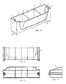
- an embodiment of the container of the invention being, respectively, a perspective view, a main elevation, a side elevation, and a plan view;
- FIGS. 5 to 8 another container being a second embodiment of the invention
- FIGS. 9 to 12 another container being a third embodiment of the invention.
- FIGS. 13 to 16 another container being a fourth embodiment of the invention.
- FIGS. 17 to 20 another embodiment of the invention.
- FIGS. 21 , 22 and 23 a and b respectively, an elevation and plan view of the container connectors
- a base for the container being, respectively, a plan view, a main elevation and a side elevation;
- a view of the lateral support being, respectively, a main elevation, a side elevation and a plan view
- FIG. 26 a perspective view of the supporting element
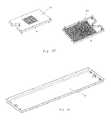
- FIG. 27 a and b respectively, a perspective view from above and from below of a grill to be placed inside the container;
- FIG. 28 a perspective view of a tray for collecting drained water
- FIG. 29 a perspective view of a suspension element
- FIG. 31 another set of modular pots.
- the modular pot of the invention consists essentially of a parallelepiped container 1 with two partition walls 2 which form three chambers 3 .
- the top ends of the container each have a sleeve 4 which forms a vertical channel 5 , the lower end 6 of the said sleeve extending beyond the bottom of the container but having slightly smaller dimensions.
- the dimensions of this lower end 6 enable the container to be fitted onto the upper end of the said channels 5 , which makes it possible to stack the containers 1 on top of each other.
- This tubular structure formed by the channels 5 joins the containers together when they are stacked vertically, and the vertical channel created by the succession of containers can be used as a drainage channel for infiltrated or irrigation water and as a guide for the insertion of a vertical tube in order to increase the stability of the whole structure.
- a supporting element 16 FIG. 26
- the said supporting element can receive a tube suited to support a profile 17 ( FIG. 29 ) for suspending and supporting a shading net or film, a protective plastic covering for creating a greenhouse and/or for installing an air irrigation system.
- the containers represented in FIGS. 5 to 15 have the same characteristics and are simply provided with conical projections in, the longer lateral walls. These projections form “bellies” which extend outwards and can be formed on one side of the container 1 or on both sides.
- the container 1 has conical projections 7 , one on each chamber 3 , but only on one side of the container 1 .
- the container 1 has the same conical projections 7 but on both sides.
- FIGS. 13 to 16 and 17 to 19 represent other embodiments of the invention.
- the container 1 has only one projection 8 with a configuration substantially similar to that of the conical projections 7 , which extends across all the chambers 3 .
- the container 1 has a projection 8 on both sides, which extends across the three chambers 3 .
- the partition wall 2 which forms the chambers 3 extends right up to the wall of the projection 8 .
- the system also includes the connectors 9 represented in FIGS. 21 to 23 , which have the function of joining adjacent containers in a horizontal plane.
- the connector 9 is formed by a ring element with two circular holes
- the connector 9 is formed by an element with three arms, each of which contains a circular hole
- the connector 9 is formed by a cross-shaped element with four arms, each of which contains a circular hole.
- these connectors make it possible, respectively, to join two containers side-by-side, three containers in the form of a triangle and four containers in four directions defined by the sides of the connector. All of the connectors 9 are placed inside the groove 10 provided for this purpose on the inside of the container 1 .
- All of the abovementioned containers have to be placed on the base 11 ( FIG. 24 ), which allows the containers to rest on the ground. They are positioned by fitting the lower end 6 into the tubular projection 12 provided on the base.
- the lateral supports 13 (represented in FIGS. 25 a, b and c ), which are exactly identical to the top end of the container 1 , make it possible, in more complex structures, to create spaces without containers and configure the side walls of such structures.
- a drainage grill 14 can be fitted ( FIG. 27 ), which is intended to create a humidity deposit at the bottom of the pot and allow radicular aeration through the channel 5 created when the containers are assembled.
- This element has the configuration of a tray with feet distributed across its inside surface for supporting the bottom of the container 1 , and a grill for aeration.
- the drained, rain or irrigation water can be collected by a tray 15 which is placed at the bottom of the container and has an appropriate configuration, as shown in FIG. 28 .
- this system also provides an innovative crop-growing solution, which makes it possible to grow at a height and in a vertical direction by stacking the containers on top of each other ( FIGS. 30 and 31 ).
- This solution is particularly appropriate for decorative and intensive agriculture and gardening.
Landscapes
- Life Sciences & Earth Sciences (AREA)
- Environmental Sciences (AREA)
- Cultivation Receptacles Or Flower-Pots, Or Pots For Seedlings (AREA)
Abstract
The present invention relates to a modular container system for use in agriculture, gardening and construction, characterized in that it comprises a parallelepiped container 1 with two partition walls 2 forming three chambers 3, its top ends each having a sleeve 4 which forms a vertical channel 5, the lower end 6 of the said sleeve extending beyond the bottom of the container but with slightly smaller dimensions and having a groove 10 around its whole periphery; connectors 9 which join adjacent containers in a horizontal plane; a base 11 which allows the containers to rest on the ground; and a lateral support 13 exactly identical to the top end of the container 1.
Description
The present invention relates to a modular container system, more specifically a system of plant pots which can be joined together by connectors and by stacking, allowing the creation of modular structures with various formats. The system can be used in agriculture, floriculture, construction of partitions, walls and pathways in open spaces, being especially suitable for use inside rooms, shopping centres and offices. In agriculture it can be used as a plant pot for growing outdoors or inside a greenhouse. It is particularly useful for growing crops using the technique of hydropony where the pots are filled with substrate instead of soil. In gardening it can be used as a pot for growing ornamental plants and in the construction industry it can be used as a decorative feature for outdoor or indoor areas, with or without plants, for forming walls, partitions or simple flower pots.
The applicant is not aware of any container systems with the characteristics mentioned in claim 1.
Of the known containers or pots, the applicant would like to mention those forming the subject matter of U.S. Pat. No. 5,511,342, DE 29720843U and DE 20014244U.
U.S. Pat. No. 5,511,342 relates to flower pots forming a self-supporting modular structure comprising a plurality of flower pots each comprising first container elements united together through at least one channel and suited to contain ornamental plants, co-axially matchable through the fixed joint formed by their matching profiles. Each of the mentioned flower pots can be co-axially matched with a second container element through the fixed joint formed by their matching profiles. Moreover, each of the said container elements fits co-axially inside an underpot tray.
Patent DE 29720843U relates to a modular construction for flower pots, boxes, trays, etc. in which each of the construction modules is diamond shaped, comprising two triangular elements and being truncated at each of the four corners. Two projections formed by three parts are segmented into two triangular sections and one rectangular section. These projections are situated at the centre of the two front edges of the diamond-shaped portion on the longitudinal axis of the profile when viewed from the side.
Patent DE 20014244U relates to a modular receptacle in the shape of a column for house or garden plants, which comprises a series of tubular sections and separating panels with holes, and an underpot for collecting drained-off water. The various sections of the column, with a circular cross-section, can be joined together by means of a screwing connection system, possibly using screwed separation panels. The side openings for the plants can be positioned in various directions by rotating the sections. The column can be used as a simple receptacle for plants or as an architectural element suited to support loads, or for forming a partition between compartments. The receptacle of the invention consists of modular parts that are easy to assemble on top of each other, in order to constitute a receptacle for plants or a flower pot.
As may be observed, none of the documents are similar to the subject matter of this invention.
The present invention relates to a modular container with a parallelepiped configuration having two partitions that form three compartments, which are joined together, its top ends each having a sleeve forming a channel, the lower end of which ends in a projecting tubular tip. The lateral walls along the longer sides of the container can have projecting bellies.
The description that follows is based on the drawings attached hereto, which represent without any restrictive character:
in FIGS. 1 to 4 , an embodiment of the container of the invention being, respectively, a perspective view, a main elevation, a side elevation, and a plan view;
in FIGS. 5 to 8 , another container being a second embodiment of the invention;
in FIGS. 9 to 12 , another container being a third embodiment of the invention;
in FIGS. 13 to 16 , another container being a fourth embodiment of the invention;
in FIGS. 17 to 20 , another embodiment of the invention;
in FIGS. 21 , 22 and 23, a and b respectively, an elevation and plan view of the container connectors;
in FIGS. 24 a, b and c, a base for the container being, respectively, a plan view, a main elevation and a side elevation;
in FIGS. 25 a, b and c, a view of the lateral support being, respectively, a main elevation, a side elevation and a plan view;
in FIG. 26 , a perspective view of the supporting element;
in FIG. 27 , a and b respectively, a perspective view from above and from below of a grill to be placed inside the container;
in FIG. 28 , a perspective view of a tray for collecting drained water;
in FIG. 29 , a perspective view of a suspension element;
in FIG. 30 , a possible set of modular pots; and
in FIG. 31 , another set of modular pots.
As can be seen from the figures, the modular pot of the invention consists essentially of a parallelepiped container 1 with two partition walls 2 which form three chambers 3. The top ends of the container each have a sleeve 4 which forms a vertical channel 5, the lower end 6 of the said sleeve extending beyond the bottom of the container but having slightly smaller dimensions. The dimensions of this lower end 6 enable the container to be fitted onto the upper end of the said channels 5, which makes it possible to stack the containers 1 on top of each other.
This tubular structure formed by the channels 5 joins the containers together when they are stacked vertically, and the vertical channel created by the succession of containers can be used as a drainage channel for infiltrated or irrigation water and as a guide for the insertion of a vertical tube in order to increase the stability of the whole structure. A supporting element 16 (FIG. 26 ) can be inserted into this channel 5 and the said supporting element can receive a tube suited to support a profile 17 (FIG. 29 ) for suspending and supporting a shading net or film, a protective plastic covering for creating a greenhouse and/or for installing an air irrigation system.
The containers represented in FIGS. 5 to 15 have the same characteristics and are simply provided with conical projections in, the longer lateral walls. These projections form “bellies” which extend outwards and can be formed on one side of the container 1 or on both sides.
In FIGS. 5 to 8 the container 1 has conical projections 7, one on each chamber 3, but only on one side of the container 1. In FIGS. 9 to 12 the container 1 has the same conical projections 7 but on both sides.
The system also includes the connectors 9 represented in FIGS. 21 to 23 , which have the function of joining adjacent containers in a horizontal plane. In FIG. 21 the connector 9 is formed by a ring element with two circular holes, in FIG. 22 the connector 9 is formed by an element with three arms, each of which contains a circular hole, and in FIG. 23 the connector 9 is formed by a cross-shaped element with four arms, each of which contains a circular hole. As may be understood, these connectors make it possible, respectively, to join two containers side-by-side, three containers in the form of a triangle and four containers in four directions defined by the sides of the connector. All of the connectors 9 are placed inside the groove 10 provided for this purpose on the inside of the container 1.
All of the abovementioned containers have to be placed on the base 11 (FIG. 24 ), which allows the containers to rest on the ground. They are positioned by fitting the lower end 6 into the tubular projection 12 provided on the base.
The lateral supports 13 (represented in FIGS. 25 a, b and c), which are exactly identical to the top end of the container 1, make it possible, in more complex structures, to create spaces without containers and configure the side walls of such structures.
Inside the chambers 3 a drainage grill 14 can be fitted (FIG. 27 ), which is intended to create a humidity deposit at the bottom of the pot and allow radicular aeration through the channel 5 created when the containers are assembled. This element has the configuration of a tray with feet distributed across its inside surface for supporting the bottom of the container 1, and a grill for aeration.
The drained, rain or irrigation water can be collected by a tray 15 which is placed at the bottom of the container and has an appropriate configuration, as shown in FIG. 28 .
As well as the numerous construction solutions resulting from the multiple assembly combinations offered by the containers, connectors and supporting parts, this system also provides an innovative crop-growing solution, which makes it possible to grow at a height and in a vertical direction by stacking the containers on top of each other (FIGS. 30 and 31 ). This solution is particularly appropriate for decorative and intensive agriculture and gardening. As an example, we would point out the advantages of using this technique for growing strawberries, which include the possibility of growing the fruit without any contact with the ground, easy harvesting and, most importantly, a yield per m2 of occupied area six times higher (in the case of flower pots stacked in six rows) than the traditional solution.
Claims (11)
1. A modular container system for use in agriculture, gardening and construction, characterised in that it comprises:
a parallelepiped container with two partition walls forming three chambers, its top ends each having a sleeve which forms a vertical channel, the lower end of said sleeve extending beyond the bottom of the container but with slightly smaller dimensions and having a groove around its whole periphery;
connectors which join adjacent containers in a horizontal plane,
a base which allows the containers to rest on the ground;
a lateral support exactly identical to the top end of the container;
a grill intended to create a humidity deposit at the bottom of the pot and allow radicular aeration;
a tray for collecting drained water;
a supporting element and a profile for suspending and supporting a shading net or film, a protective plastic covering for creating a greenhouse and/or for installing an air irrigation system.
2. A modular container system, according to claim 1 , characterised in that longer lateral side walls of the container can have conical projections forming “bellies” which extend outwards and can be formed on one side of the container or on both sides.
3. A modular container system, according to claim 2 , characterised in that the conical projections can extend across all the chambers, forming a single projecting belly, or can be provided in each of the chambers forming three projecting bellies.
4. A modular container system, according to claim 3 , characterised in that in the case of the conical projection which extends across all three chambers, the partition wall of the chambers extends right up to the wall of the projection.
5. A modular container system, according to claim 1 , characterised in that the lower ends enable the container to be fitted onto the upper end of the channels, making it possible to stack the containers on top of each other.
6. A modular, container system, according to claim 1 , characterised in that the connectors which join adjacent containers in a horizontal plane have the configuration of a ring element with two holes, of an element with three arms each containing a hole and of a cross with four holes, being intended, respectively, for joining the containers side-by-side, in the form of a triangle and in the form of a cross.
7. A modular container system, according to claim 6 , characterised in that the connectors are placed inside the groove provided for this purpose on the inside of the container.
8. A modular container system, according to claim 1 , characterised in that the tubular structure formed by the channels joins the containers together when they are stacked vertically, and the vertical channel created by the succession of containers can be used as a drainage channel for infiltrated or irrigation water and as a guide for the insertion of a vertical tube in order to increase the stability of the whole structure.
9. A modular container system, according to claim 1 , characterised in that inside the chambers the drainage grill can be fitted, which is intended to create a humidity deposit at the bottom of the pot and allow radicular aeration through the channel created when the containers are assembled, said grill having the configuration of a tray with feet distributed across its inside surface for supporting the bottom of the container, and an actual grill portion for aeration.
10. A modular container system, according to claim 1 , characterised in that the drained water can be collected by the tray.
11. A modular container system, according to claim 1 , characterised in that the lateral support makes it possible, in more complex structures, to create spaces without containers and configure the side walls of such structures.
Applications Claiming Priority (1)
| Application Number | Priority Date | Filing Date | Title |
|---|---|---|---|
| PCT/PT2006/000003 WO2007084020A1 (en) | 2006-01-23 | 2006-01-23 | Modular container system |
Publications (2)
| Publication Number | Publication Date |
|---|---|
| US20100186295A1 US20100186295A1 (en) | 2010-07-29 |
| US8341884B2 true US8341884B2 (en) | 2013-01-01 |
Family
ID=37057327
Family Applications (1)
| Application Number | Title | Priority Date | Filing Date |
|---|---|---|---|
| US12/161,761 Active 2027-08-21 US8341884B2 (en) | 2006-01-23 | 2006-01-23 | Modular container system |
Country Status (13)
| Country | Link |
|---|---|
| US (1) | US8341884B2 (en) |
| EP (1) | EP1976372B1 (en) |
| JP (1) | JP5166285B2 (en) |
| CN (1) | CN101394734B (en) |
| AU (1) | AU2006335700B2 (en) |
| BR (1) | BRPI0621014B1 (en) |
| CA (1) | CA2637935C (en) |
| DK (1) | DK1976372T3 (en) |
| ES (1) | ES2595497T3 (en) |
| HU (1) | HUE031154T2 (en) |
| PL (1) | PL1976372T3 (en) |
| PT (1) | PT1976372T (en) |
| WO (1) | WO2007084020A1 (en) |
Cited By (5)
| Publication number | Priority date | Publication date | Assignee | Title |
|---|---|---|---|---|
| US20110036008A1 (en) * | 2007-08-21 | 2011-02-17 | Suntory Holdings Limited | Planting container |
| US20110154744A1 (en) * | 2009-12-29 | 2011-06-30 | Brad Bowen | Modular living wall component and system |
| USD800013S1 (en) * | 2015-12-17 | 2017-10-17 | Diana Marcela Cabeza | Planter |
| US10653075B1 (en) * | 2018-12-07 | 2020-05-19 | Timothy E. Joseph | Modular grow chamber constructions and related growing systems and methods |
| USD922250S1 (en) * | 2016-07-01 | 2021-06-15 | Green Roof Outfitters, LLC | Green roof module |
Families Citing this family (9)
| Publication number | Priority date | Publication date | Assignee | Title |
|---|---|---|---|---|
| JP5319498B2 (en) | 2009-11-10 | 2013-10-16 | サントリーホールディングス株式会社 | Planting container |
| DE102010029172B4 (en) * | 2010-05-20 | 2012-08-30 | Geobra Brandstätter GmbH & Co. KG | Planting arrangement |
| AU2013260271B2 (en) | 2012-04-03 | 2017-06-01 | Quizcamp-Fabrico E Comercio De Produtos Alimentares, S.A. | Modular integrated system for seed germination, cultivation, planting, fertilizing and maintenance of plants |
| CN103026916B (en) * | 2012-12-19 | 2014-12-17 | 斯泰科技(杭州)有限公司 | Strip-shaped planting pot suitable for agricultural production of ships and household balconies |
| CN104335836A (en) * | 2013-08-11 | 2015-02-11 | 孙希贤 | Combined type greening body |
| JP2016202138A (en) * | 2015-04-28 | 2016-12-08 | 株式会社タカショー | Drainboard-like member for planters, planter and plant culture device |
| CN106962053A (en) * | 2017-05-17 | 2017-07-21 | 黄德修 | A kind of green plant brick and its green plant wall of formation |
| EP3644708B1 (en) * | 2017-06-30 | 2023-10-04 | Husqvarna AB | Pot for gardening |
| GB2584812B (en) * | 2019-02-08 | 2022-03-02 | Alexander Sabin Richard | Stackable modular planter |
Citations (11)
| Publication number | Priority date | Publication date | Assignee | Title |
|---|---|---|---|---|
| US523991A (en) * | 1894-08-07 | Apparatus for growing plants | ||
| US3389499A (en) * | 1966-10-20 | 1968-06-25 | Haile Ernest | Planting wall |
| US4614056A (en) * | 1985-01-22 | 1986-09-30 | F.F. Plastics R.D. Inc. | Stacking planters |
| US4964761A (en) * | 1988-09-30 | 1990-10-23 | Rossi Jean Louis | Retaining wall adapted to be provided with vegetation, comprising openings serving as a concealed framing for concrete |
| US5511342A (en) | 1992-11-18 | 1996-04-30 | Abruzzovasi Srl | Flower-pots forming a modular structure |
| DE29720843U1 (en) | 1997-12-02 | 1999-04-01 | Schubecker Alexander | Repotting aid for flower pots, flower boxes, troughs, etc. |
| WO2000004758A1 (en) | 1998-07-23 | 2000-02-03 | Bouma, Johanna, Catharina | Improvements to edging |
| DE20014244U1 (en) | 2000-08-17 | 2001-02-22 | Polifke Harald | Plant pillar for inside and outside |
| GB2400119A (en) | 2003-04-02 | 2004-10-06 | Leo Kinsella | Partition system for growing plants |
| US20080092442A1 (en) * | 2004-03-04 | 2008-04-24 | Modular Merchants, Inc., Dba Gardens To Grow A California Corporation | Garden bed assembly and method and kit therefor |
| US20100313474A1 (en) * | 2009-06-12 | 2010-12-16 | Eleanor's Garden, Llc | Modular Gardening System |
Family Cites Families (15)
| Publication number | Priority date | Publication date | Assignee | Title |
|---|---|---|---|---|
| JPS6033842U (en) * | 1983-05-02 | 1985-03-08 | 村岡 加代子 | Three-dimensional decorative pot with water channel |
| JPS60127727U (en) * | 1984-02-03 | 1985-08-28 | ニチゾウモデルエンジニアリング株式会社 | Multi-stage cultivation equipment |
| JPS61141405U (en) * | 1985-02-23 | 1986-09-01 | ||
| JPH05308853A (en) * | 1992-05-08 | 1993-11-22 | Fukukyu Hen | Stacking type cultivation container |
| JP3017512U (en) * | 1995-04-28 | 1995-10-31 | アイリスオーヤマ株式会社 | Tiered planter |
| JP3549130B2 (en) * | 1995-06-30 | 2004-08-04 | 株式会社淺沼組 | Planting wall and planting container used for it |
| JPH1075664A (en) * | 1996-09-03 | 1998-03-24 | Shigeru Kashiwagi | Plant pot for stacking to form imitation tree |
| CN2292381Y (en) * | 1997-03-04 | 1998-09-30 | 周之杰 | Combined trough receptacle for cultivation of plant |
| JP3029604B2 (en) * | 1998-08-07 | 2000-04-04 | 高秀 井上 | planter |
| JP2000262153A (en) * | 1999-03-15 | 2000-09-26 | Fukuoka Marumoto Kk | Container for culture |
| CN1242932A (en) * | 1999-07-09 | 2000-02-02 | 陆昌石 | Assembling method for planting trees to make some place green, and special implement |
| JP3320689B2 (en) * | 1999-09-09 | 2002-09-03 | 茂 五味 | Prefabricated flower pot |
| JP2002142570A (en) * | 2000-08-29 | 2002-05-21 | Toho Kogyo Kk | Planter for gardening capable of adjusting height |
| JP2002097653A (en) * | 2000-09-22 | 2002-04-02 | Kajima Corp | Unitized panel for planting wall surface |
| JP2003061473A (en) * | 2001-08-28 | 2003-03-04 | Kazuhiro Okuda | Connection type container |
-
2006
- 2006-01-23 HU HUE06700793A patent/HUE031154T2/en unknown
- 2006-01-23 JP JP2008551210A patent/JP5166285B2/en active Active
- 2006-01-23 DK DK06700793.0T patent/DK1976372T3/en active
- 2006-01-23 AU AU2006335700A patent/AU2006335700B2/en active Active
- 2006-01-23 CA CA2637935A patent/CA2637935C/en active Active
- 2006-01-23 US US12/161,761 patent/US8341884B2/en active Active
- 2006-01-23 BR BRPI0621014-7B1A patent/BRPI0621014B1/en active IP Right Grant
- 2006-01-23 WO PCT/PT2006/000003 patent/WO2007084020A1/en active Application Filing
- 2006-01-23 ES ES06700793.0T patent/ES2595497T3/en active Active
- 2006-01-23 EP EP06700793.0A patent/EP1976372B1/en active Active
- 2006-01-23 PT PT67007930T patent/PT1976372T/en unknown
- 2006-01-23 CN CN2006800536898A patent/CN101394734B/en active Active
- 2006-01-23 PL PL06700793T patent/PL1976372T3/en unknown
Patent Citations (11)
| Publication number | Priority date | Publication date | Assignee | Title |
|---|---|---|---|---|
| US523991A (en) * | 1894-08-07 | Apparatus for growing plants | ||
| US3389499A (en) * | 1966-10-20 | 1968-06-25 | Haile Ernest | Planting wall |
| US4614056A (en) * | 1985-01-22 | 1986-09-30 | F.F. Plastics R.D. Inc. | Stacking planters |
| US4964761A (en) * | 1988-09-30 | 1990-10-23 | Rossi Jean Louis | Retaining wall adapted to be provided with vegetation, comprising openings serving as a concealed framing for concrete |
| US5511342A (en) | 1992-11-18 | 1996-04-30 | Abruzzovasi Srl | Flower-pots forming a modular structure |
| DE29720843U1 (en) | 1997-12-02 | 1999-04-01 | Schubecker Alexander | Repotting aid for flower pots, flower boxes, troughs, etc. |
| WO2000004758A1 (en) | 1998-07-23 | 2000-02-03 | Bouma, Johanna, Catharina | Improvements to edging |
| DE20014244U1 (en) | 2000-08-17 | 2001-02-22 | Polifke Harald | Plant pillar for inside and outside |
| GB2400119A (en) | 2003-04-02 | 2004-10-06 | Leo Kinsella | Partition system for growing plants |
| US20080092442A1 (en) * | 2004-03-04 | 2008-04-24 | Modular Merchants, Inc., Dba Gardens To Grow A California Corporation | Garden bed assembly and method and kit therefor |
| US20100313474A1 (en) * | 2009-06-12 | 2010-12-16 | Eleanor's Garden, Llc | Modular Gardening System |
Cited By (6)
| Publication number | Priority date | Publication date | Assignee | Title |
|---|---|---|---|---|
| US20110036008A1 (en) * | 2007-08-21 | 2011-02-17 | Suntory Holdings Limited | Planting container |
| US9769991B2 (en) * | 2007-08-21 | 2017-09-26 | Suntory Holdings Limited | Planting container |
| US20110154744A1 (en) * | 2009-12-29 | 2011-06-30 | Brad Bowen | Modular living wall component and system |
| USD800013S1 (en) * | 2015-12-17 | 2017-10-17 | Diana Marcela Cabeza | Planter |
| USD922250S1 (en) * | 2016-07-01 | 2021-06-15 | Green Roof Outfitters, LLC | Green roof module |
| US10653075B1 (en) * | 2018-12-07 | 2020-05-19 | Timothy E. Joseph | Modular grow chamber constructions and related growing systems and methods |
Also Published As
| Publication number | Publication date |
|---|---|
| PL1976372T3 (en) | 2017-01-31 |
| AU2006335700A1 (en) | 2007-07-26 |
| CA2637935A1 (en) | 2007-07-26 |
| AU2006335700B2 (en) | 2012-07-12 |
| PT1976372T (en) | 2017-04-24 |
| BRPI0621014B1 (en) | 2014-12-30 |
| CN101394734A (en) | 2009-03-25 |
| CN101394734B (en) | 2011-11-23 |
| EP1976372B1 (en) | 2016-07-06 |
| US20100186295A1 (en) | 2010-07-29 |
| ES2595497T3 (en) | 2016-12-30 |
| BRPI0621014A2 (en) | 2011-11-29 |
| DK1976372T3 (en) | 2016-11-07 |
| WO2007084020A1 (en) | 2007-07-26 |
| JP5166285B2 (en) | 2013-03-21 |
| HUE031154T2 (en) | 2017-06-28 |
| CA2637935C (en) | 2013-11-12 |
| JP2009523444A (en) | 2009-06-25 |
| EP1976372A1 (en) | 2008-10-08 |
Similar Documents
| Publication | Publication Date | Title |
|---|---|---|
| US8341884B2 (en) | Modular container system | |
| US11684021B2 (en) | Vertical hydroponic plant production apparatus | |
| US3686791A (en) | Walls, screens and the like | |
| US20050155287A1 (en) | Container system for growing plants | |
| US8904706B1 (en) | Modular interlocking planter | |
| KR20160022968A (en) | Variable modular kitchen garden | |
| CN203261849U (en) | Split mounting type planting box | |
| KR200402153Y1 (en) | Vine cultivation flowerpot | |
| EP0964613A1 (en) | Three-dimensional modular cultivation container | |
| US20120204486A1 (en) | Prefabricated gardening apparatus | |
| US20220322613A1 (en) | Modular Planting System | |
| KR102322640B1 (en) | Prefabricated Flowerpot | |
| RU2407279C2 (en) | System of modular containers | |
| KR200470118Y1 (en) | The interior vegetable garden cultivation receptacle | |
| JPS64746Y2 (en) | ||
| RU109368U1 (en) | MODULE FOR PLANT GROWING | |
| TWI714077B (en) | Modular planting and breeding box components | |
| KR20170066191A (en) | A multistage cultivator for vegetable garden | |
| US20220369571A1 (en) | Interengageable containers and methods | |
| US11006582B2 (en) | Interlocking tongue and groove vegetation planting assembly | |
| JPS61177929A (en) | Three-dimensional culture system | |
| IL108069A (en) | Construction system for holding plants and elements therefor |
Legal Events
| Date | Code | Title | Description |
|---|---|---|---|
| AS | Assignment |
Owner name: QUIZCAMP-FABRICO E. COMERCIO DE PRODUTOS ALIMENTAR Free format text: ASSIGNMENT OF ASSIGNORS INTEREST;ASSIGNOR:RODRIGUES, MANUEL MARIA;REEL/FRAME:024193/0736 Effective date: 20080818 |
|
| STCF | Information on status: patent grant |
Free format text: PATENTED CASE |
|
| FPAY | Fee payment |
Year of fee payment: 4 |
|
| MAFP | Maintenance fee payment |
Free format text: PAYMENT OF MAINTENANCE FEE, 8TH YEAR, LARGE ENTITY (ORIGINAL EVENT CODE: M1552); ENTITY STATUS OF PATENT OWNER: LARGE ENTITY Year of fee payment: 8 |