EP4045889B1 - Messautomat, fertigungsanlage und verfahren - Google Patents
Messautomat, fertigungsanlage und verfahren Download PDFInfo
- Publication number
- EP4045889B1 EP4045889B1 EP20797688.7A EP20797688A EP4045889B1 EP 4045889 B1 EP4045889 B1 EP 4045889B1 EP 20797688 A EP20797688 A EP 20797688A EP 4045889 B1 EP4045889 B1 EP 4045889B1
- Authority
- EP
- European Patent Office
- Prior art keywords
- test piece
- solid
- measuring machine
- weighing
- wet
- Prior art date
- Legal status (The legal status is an assumption and is not a legal conclusion. Google has not performed a legal analysis and makes no representation as to the accuracy of the status listed.)
- Active
Links
Images


Classifications
-
- G—PHYSICS
- G01—MEASURING; TESTING
- G01N—INVESTIGATING OR ANALYSING MATERIALS BY DETERMINING THEIR CHEMICAL OR PHYSICAL PROPERTIES
- G01N9/00—Investigating density or specific gravity of materials; Analysing materials by determining density or specific gravity
- G01N9/08—Investigating density or specific gravity of materials; Analysing materials by determining density or specific gravity by measuring buoyant force of solid materials by weighing both in air and in a liquid
-
- G—PHYSICS
- G01—MEASURING; TESTING
- G01N—INVESTIGATING OR ANALYSING MATERIALS BY DETERMINING THEIR CHEMICAL OR PHYSICAL PROPERTIES
- G01N9/00—Investigating density or specific gravity of materials; Analysing materials by determining density or specific gravity
- G01N9/36—Analysing materials by measuring the density or specific gravity, e.g. determining quantity of moisture
-
- G—PHYSICS
- G01—MEASURING; TESTING
- G01N—INVESTIGATING OR ANALYSING MATERIALS BY DETERMINING THEIR CHEMICAL OR PHYSICAL PROPERTIES
- G01N9/00—Investigating density or specific gravity of materials; Analysing materials by determining density or specific gravity
- G01N9/02—Investigating density or specific gravity of materials; Analysing materials by determining density or specific gravity by measuring weight of a known volume
- G01N2009/022—Investigating density or specific gravity of materials; Analysing materials by determining density or specific gravity by measuring weight of a known volume of solids
-
- Y—GENERAL TAGGING OF NEW TECHNOLOGICAL DEVELOPMENTS; GENERAL TAGGING OF CROSS-SECTIONAL TECHNOLOGIES SPANNING OVER SEVERAL SECTIONS OF THE IPC; TECHNICAL SUBJECTS COVERED BY FORMER USPC CROSS-REFERENCE ART COLLECTIONS [XRACs] AND DIGESTS
- Y02—TECHNOLOGIES OR APPLICATIONS FOR MITIGATION OR ADAPTATION AGAINST CLIMATE CHANGE
- Y02P—CLIMATE CHANGE MITIGATION TECHNOLOGIES IN THE PRODUCTION OR PROCESSING OF GOODS
- Y02P10/00—Technologies related to metal processing
- Y02P10/25—Process efficiency
Definitions
- the invention relates to an automatic measuring device for determining the density of solid test pieces.
- the automatic measuring device is used in particular in an industrial environment, for example in a production hall in which industrial production of solid test pieces conveniently takes place.
- the solid test pieces are, for example, workpieces, in particular workpieces that are manufactured using additive manufacturing, in particular 3D printing.
- the term "solid test piece" is intended in particular to express that the test piece is not liquid.
- the solid test pieces can be workpieces that were manufactured using sintering, casting, injection molding or another process.
- the US$5,606,126 relates to a device for automatically measuring a density of an object.
- the CN109 883 881 A concerns a weighing device.
- An object of the invention is to provide an automatic measuring device which enables an efficient determination of the density of a plurality of solid test pieces.
- the measuring machine serves for the automated determination of the respective density of a plurality of Solid test pieces.
- the measuring machine comprises a measuring arrangement with a dry scale device and a wet scale device.
- the measuring machine further comprises a test piece magazine for receiving the plurality of solid test pieces.
- the measuring machine further comprises a feed unit for feeding the solid test pieces from the test piece magazine to the measuring arrangement.
- the measuring machine is designed to sequentially feed the solid test pieces to the measuring arrangement using the feed unit.
- the measuring machine is further designed to weigh the solid test pieces using the dry scale device and the wet scale device in order to obtain respective weighing measurements for each solid test piece.
- the measuring machine is further designed to determine a respective density value for each solid test piece on the basis of the respective weighing measurements.
- the measuring machine described enables an efficient determination of the density of a plurality of solid test pieces.
- the measuring machine is designed in particular to determine the density of the solid test pieces fully automatically.
- the measuring machine is designed to handle the solid test pieces fully automatically for the determination of the density.
- the test piece magazine comprises a plurality of test piece carriers, each of which serves to accommodate a respective test piece, and wherein the feed unit is designed to remove the test piece carriers sequentially from the test piece magazine in order to feed the test pieces in the respective test piece carrier to the measuring arrangement.
- the measuring machine comprises a measuring machine housing which surrounds a working space in which the measuring arrangement and the test piece magazine are arranged.
- the measuring machine comprises a vibration damping suspension which supports the wet weighing device and is designed to dampen mechanical vibrations originating from the environment of the measuring machine in order to reduce their influence on the weighing measurements.
- the measuring machine comprises a frame structure with which the test piece magazine and the feed unit are supported relative to a floor on which the measuring machine stands, and wherein the wet weighing device is vibration-decoupled from the frame structure.
- the measuring machine comprises a work space floor on which the test piece magazine stands, wherein the work space floor comprises a wet scale recess through which a wet scale structure extends, which comprises the vibration damping suspension and the wet scale device.
- the measuring machine is designed to carry out the weighing of each test piece using the dry weighing device and the wet weighing device in a state in which the test piece is located within a receiving area of the respective test piece carrier.
- the dry weighing device and/or the wet weighing device each comprise a test piece lifting structure which engages the respective test piece carrier when weighing a solid test piece and, in particular when lowering the respective test piece carrier, causes the solid test piece to be lifted relative to the test piece carrier.
- the wet weighing device comprises a basin filled with a liquid, a first weighing unit arranged outside the basin and a force transmission structure leading from the first weighing unit into the basin, which is designed to transmit the force exerted by the solid test piece in the liquid on the force transmission structure from the basin to the first weighing unit when weighing a solid test piece with the wet weighing device.
- the wet weighing device comprises a/the basin and a first test piece lifting structure arranged in the basin, which engages in a respective test piece carrier when weighing a solid test piece and, in particular when lowering the respective test piece carrier, causes the solid test piece to be lifted relative to the test piece carrier.
- the wet weighing device comprises a/the basin and a liquid level control device for controlling the liquid level of the basin.
- the measuring machine is designed to weigh the solid test piece using the wet weighing device by immersing the solid test piece together with a respective test piece carrier into the liquid of the basin and to control the liquid level after immersing the test piece carrier.
- the wet weighing device comprises a basin and a surfactant is added to a liquid with which the basin is filled.
- the measuring machine is designed to carry out the determination of the density for those solid test pieces that are located at the test piece locations that are indicated by the selection information, on the basis of selection information that indicates one or more test piece locations of the test piece magazine.
- the measuring machine comprises an interface, in particular a user interface, for entering the selection information.
- a plurality of solid-state test pieces produced by additive manufacturing are arranged in the test piece magazine.
- the measuring machine is preferably designed to assess the manufacturing quality of the respective solid test piece on the basis of the determined density values and to provide assessment information.
- the invention further relates to a production plant comprising a production hall, a production device arranged in the production hall for producing solid-state test pieces and an automatic measuring device arranged in the production hall, which is designed as described above.
- the invention further relates to a method according to claim 14 for the automated determination of the respective density of a plurality of solid test pieces, comprising the steps of: feeding, by means of a feeding unit, the solid test pieces from a test piece magazine to a measuring arrangement which comprises a dry balance device and a wet balance device, weighing the solid test pieces using the dry balance device and the wet balance device to obtain respective weighing measurements for each solid test piece, and determining for each solid test piece a respective density value based on the respective weighing measurements.
- the invention further relates to a method according to claim 15 for assessing the manufacturing quality of a solid-state test piece produced by means of an additive process, comprising the steps of: weighing the solid-state test piece with a dry-scale device and a wet-scale device in order to obtain weighing measurements, assessing the manufacturing quality of the solid-state test piece on the basis of the weighing measurements and providing assessment information about the manufacturing quality of the solid-state test piece.
- the assessment information expediently indicates whether the solid-state test piece achieves a predetermined manufacturing quality.
- the assessment information indicates whether the solid-state test piece has an inclusion, for example an air inclusion.
- the solid-state test piece is, for example, a workpiece.
- the x-direction can also be referred to as the width direction, the y-direction as the depth direction and the z-direction as the height direction.
- the x-direction and the y-direction are horizontal directions; the z-direction is a vertical direction.
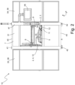
- the Figures 1 to 3 show an automatic measuring device 10 according to an exemplary embodiment.
- the automatic measuring device 10 is designed in particular to carry out an automated determination of the respective density of a plurality of solid test pieces 1.
- the automatic measuring device 10 comprises a measuring arrangement 2 with a dry weighing device 3 and a wet weighing device 4.
- the automatic measuring device 10 further comprises a test piece magazine 5 for receiving the plurality of solid test pieces 1.
- the automatic measuring device 10 further comprises a feed unit 6 for feeding the solid test pieces 1 from the test piece magazine 5 to the measuring arrangement 2.
- the measuring machine 10 is designed to automatically convey the solid test pieces 1 from the test piece magazine 5 to the measuring arrangement 2 using the feed unit 6.
- the measuring machine 10 is designed to convey the solid test pieces 1 sequentially from the test piece magazine 5 to the measuring arrangement 2.
- the measuring machine 10 conveys the solid test pieces 1 individually from the test piece magazine 5 to the measuring arrangement 2, in particular (one after the other) to the dry balance device 3 and to the wet balance device 4 and then expediently back to the test piece magazine 5.
- the measuring machine 10 completes the feeding of a solid test piece 1 to the measuring arrangement 2 and back to the test piece magazine 5 before the measuring machine 10 feeds a next solid test piece 1 to the measuring arrangement 2.
- the automatic measuring device 10 is expediently designed to automatically weigh the solid test pieces 1 using the dry weighing device 3 and the wet weighing device 4 in order to obtain respective weighing measurements for each solid test piece 1, in particular a dry weighing measurement value and a wet weighing measurement value.
- the automatic measuring device 10 is preferably designed to automatically determine, in particular to calculate, a respective density value for each solid test piece 1 on the basis of the respective weighing measurements.
- the automatic measuring device 10 is designed to carry out the feeding and weighing of the solid test piece 1 and the determination of the density fully automatically - i.e. without user intervention.
- the measuring machine 10 is designed, for example, to calculate the density value based on the dry weighing measurement value and the wet weighing measurement value using the Archimedes principle.
- ⁇ is the density of the solid test piece 1
- ⁇ w is the density of the liquid 19 of the wet weighing device 4
- ⁇ l is the density of the air (for example in the working space 8)
- F l is the weight of the solid test piece 1 in the air on which the dry weighing measurement value is based
- F w is the weight of the solid test piece 1 in the water on which the wet weighing measurement value is based.
- the automatic measuring device 10 is designed to assess the manufacturing quality of the respective solid test piece 1 on the basis of the determined density value and to provide assessment information.
- the automatic measuring device 10 is designed to compare the determined density value with a specified value, in particular a specified value range, and to provide the assessment information on the basis of the comparison.
- the assessment information expediently indicates whether a solid test piece has a specified density and/or is in a specified density range.
- the measuring machine 10 uses the density value to determine whether the solid test piece 1 has one or more inclusions, for example air inclusions, and provides assessment information that indicates this.
- the assessment of the manufacturing quality based on the density value has the particular advantage over the conventional cross-sectional image assessment that it can be carried out non-destructively and/or more quickly.
- the assessment of the manufacturing quality is carried out in particular for an additively manufactured solid-state test piece.
- the measuring device 10 comprises a first temperature sensor that measures the temperature of the liquid 19, a second temperature sensor that measures the temperature of the air in the working space 8 and/or an air pressure sensor that measures the air pressure in the working space 8.
- the measuring device 10 is expediently designed to calculate the density taking into account one or more sensor values that are detected by means of the first temperature sensor, the second temperature sensor and/or the air pressure sensor.
- the measuring device 10 is expediently designed to determine the density with a repeatability of 0.5 mg/cm ⁇ 3 or less and/or a resolution of 0.1 mg/cm ⁇ 3 or less.
- the measuring machine 10 comprises, as an example, a measuring machine housing 7.
- the measuring machine 10, in particular the measuring machine housing 7, has, as an example, a cuboid-shaped basic shape, wherein the Height is expediently greater, in particular at least twice as large as the width and/or depth of the measuring machine.
- the measuring machine, in particular the measuring machine housing 7, is at least 1.60 m high and/or at least 80 cm deep and/or wide.
- the measuring machine housing 7 comprises, by way of example, four peripheral walls: a front wall 31, a rear wall 32, a first side wall 33 and a second side wall 34.
- the peripheral walls are expediently completely closable and serve in particular to protect the measuring arrangement, in particular the wet balance device 4, from air vibrations.
- the front wall 31 and the rear wall 32 are aligned parallel to one another, in particular perpendicular to the y-direction.
- the first side wall 33 and the second side wall 34 are aligned parallel to one another (when the associated doors are closed), in particular perpendicular to the x-direction.
- the measuring machine housing 7 comprises, by way of example, a housing base 35 from which the four peripheral walls extend upwards in the z-direction.
- the housing base is aligned perpendicular to the z-direction.
- the measuring machine housing 7 further comprises a housing cover 36, which expediently forms the upper end of the measuring machine housing 7 and up to which the peripheral walls extend vertically.
- the housing cover 36 is aligned perpendicular to the z-direction.
- the front wall 31 comprises, for example, a front door 37
- the first side wall 33 comprises, for example, a first side door 38
- the second side wall 34 comprises, for example, a second side door 39.
- the front door 37, the first side door 38 and/or the second side door 39 are expediently mounted so as to be pivotable about a respective pivot axis running parallel to the z-direction.
- the front door 37, the first side door 38 and the second side door 39 are shown in an open state.
- the front wall 31 in particular the front door 37, there is an exemplary assembly opening 44, in particular an assembly hatch, through which the measuring machine 10 can be equipped with solid-state test pieces 1.
- the measuring machine 10 expediently has an opening mechanism to automatically open and/or close the assembly opening 44.
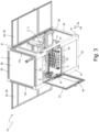
- the measuring machine 10 comprises a frame structure 11 with which the dry scale device 3, the test piece magazine 5 and/or the feed unit 6 are supported against the floor on which the measuring machine 10 stands.
- the frame structure 11 is designed in particular as a base frame.
- the frame structure 11 forms, for example, part of the measuring machine housing 7.
- the frame structure 11 comprises, for example, four elongated vertical support elements 41 aligned in the z-direction, which are preferably designed as continuous cast profiles, in particular as continuous cast aluminum profiles.
- the vertical support elements 41 form, for example, the edges of the cuboid basic shape of the measuring machine 10 that run parallel to the z-direction.
- Stand feet 42 are arranged, for example, on the underside of the vertical support elements 41.
- the frame structure 11 further comprises a plurality of elongated horizontal support elements 43, for example at least four, eight or twelve horizontal support elements 43.
- the horizontal support elements 43 are each aligned in a horizontal direction and are expediently designed as extruded profiles, in particular as extruded aluminum profiles.
- the horizontal support elements 43 are supported by the vertical support elements 41 and are in particular attached to them.
- four horizontal support elements are each 43 are arranged at the same height and together form in particular a rectangular or square frame.
- the housing base 35 and/or the housing cover 36 is supported by the vertical support elements 41 and/or the horizontal support elements 43.
- the measuring machine 10 further comprises a work space base 12, which is expediently supported by the vertical support elements 41 and/or the horizontal support elements 43.
- the measuring machine 10 comprises a working space 8 in which the test piece magazine 5, the measuring arrangement 2, in particular the dry scale device 3 and the wet scale device 4, and the feed unit 6 are expediently arranged.
- the working space 8 has, for example, a cuboid-shaped basic shape.
- the working space 8 is surrounded by the measuring machine housing 7, in particular the peripheral walls.
- the measuring machine 10 is expediently designed to put the working space 8 into a state that is completely closed off from the surroundings of the measuring machine 10, for example by closing the assembly opening 44. In this state, the wet scale device 4 is protected from air vibrations.
- the working space 8 is limited at the bottom by the working space floor 12.
- the test piece magazine 5 and the dry scale device 3 are expediently located on the work area floor 12.
- the work area 8 takes up at least 30%, in particular at least 50% of the vertical extension of the measuring machine housing 7.
- the work area floor 12 is located, for example, at a height of at least 20% of the height of the measuring machine housing 7.
- the work area 8 is located at a working height suitable for a standing user, so that a standing user can reach into the work area 8, for example through the equipment opening 44.
- the working space 8 surrounded by the peripheral walls serves in particular to protect the wet balance device 4 from air vibrations in the environment of the measuring machine 10. This can prevent the measurement results from being affected by air vibrations. Because the test piece magazine 5 is located in the working space 8, the solid test pieces 1 can be transported quickly to the measuring arrangement 2.
- the measuring machine 10 further comprises a supply chamber 45.
- the supply chamber 45 is surrounded by the measuring machine housing 7, in particular the peripheral walls.
- the supply chamber 45 is located in particular under the working chamber 8.
- the supply chamber 45 is limited at the top by the working chamber floor 12 and at the bottom, expediently, by the housing floor 35.
- the measuring machine 10 comprises at least one liquid container 46, which is expediently arranged in the supply space 45.
- the liquid container 46 expediently comprises liquid for the wet weighing device 4 and is expediently fluidically connected to the wet weighing device 4, in particular via a pump.
- the liquid container 46 is exemplarily part of a liquid level control device 25.
- the liquid container 46 is a feed container and the measuring machine can additionally comprise a drain container, which can be arranged in the supply space 45.
- the measuring machine is expediently designed to convey liquid from the feed container into the basin 21 and/or liquid 19 from the basin 21 into the drain container to drain, in particular by means of the liquid level control device 25.
- the measuring machine 10 comprises an interface 26, which is designed in particular as a user interface.
- the interface 26 comprises a display and/or an operating device.
- the interface 26 comprises a touchscreen.
- the interface 26, in particular the user interface is attached, by way of example, to the outside of the measuring machine housing 7, preferably at the level of the work area 8.
- selection information can be entered via the interface 26, which determines one or more test piece locations of the test piece magazine 5.
- the measuring machine 10 is expediently designed to carry out the determination of the density for the solid test pieces 1 that are located at the test piece locations determined by the selection information on the basis of the selection information.
- the measuring machine 10 is expediently designed to output, in particular to display, the weighing measurement values and/or the density value and/or the assessment information via the interface 26.
- the Figure 4 shows how the measuring arrangement 2, the test piece magazine 5 and the feed unit 6 are arranged in relation to one another.
- the measuring arrangement 2 and the test piece magazine 5 are located in the same xy plane and are arranged offset from one another in the x direction and/or y direction.
- the test piece magazine 5 is arranged in front of the measuring arrangement 2 in the y direction.
- the dry scale device 3 and the wet scale device 4 are expediently spaced from one another and expediently in the x direction arranged offset from one another.
- the feed unit 6 is expediently arranged in the z-direction above the workspace floor 12, in particular above the measuring arrangement 2 and/or the test piece magazine 5.
- the feed unit 6 is designed as a robot device, in particular as a gantry robot.
- the feed unit 6 expediently comprises a gripper 47, which can be moved in an x-y plane and expediently in the z direction.
- the feed unit 6 exemplarily comprises four axes: two horizontal axes, which are expediently aligned orthogonally to one another and of which one runs parallel to the x-axis and the other parallel to the y-axis, a vertical axis and a rotation axis running in particular parallel to the z-direction.
- the feed unit 6 is expediently designed to sequentially remove test piece carriers 16 from the test piece magazine 5 in order to sequentially feed the solid test pieces 1 in a respective test piece carrier 16 to the measuring arrangement 2.
- the feed unit 6 is designed to feed each solid test piece 1 in the respective test piece carrier to the dry scale device 3 and the wet scale device 4 in order to enable the solid test piece 1 to be weighed there in the test piece carrier 16.
- the feed unit 6 is expediently designed to immerse the solid test piece 1 together with the test piece carrier 16 and expediently the gripper 47 into the liquid 19 of the wet scale device 4 in order to weigh the solid test piece 1 with the wet scale device 4.
- the gripper 47 is at least partially immersed in the liquid 19.
- the feed unit 6 comprises two linear guides 48 that run parallel to one another, in particular parallel to the y-direction.
- the feed unit 6 comprises a carriage, in particular a portal carriage, that can be moved along the linear guides 48 - i.e. in particular in the y-direction.
- the carriage 49 comprises a gripper arm 51 and a transverse guide 52 that runs orthogonally to the linear guides 48 and along which the gripper arm 51 can be moved.
- the gripper arm 51 comprises the gripper 47, which can expediently be moved in the z-direction and/or can be rotated about the axis of rotation that runs parallel to the z-direction.
- the gripper 47 is particularly suitable for Figures 14 and 15
- the gripper 47 comprises at least one gripping element 53 that can be brought into engagement with a test piece carrier 16.
- the gripper 47 comprises two gripping elements 53 that are expediently designed in the shape of a pin and/or protrude downwards in the z-direction.
- the feed unit 6 is preferably designed to carry out a gripping movement with the gripper 47 in order to bring the gripping elements 53 into engagement with the test piece carrier 16.
- the gripping movement in particular comprises a rotation of the gripper 47 about the axis of rotation running parallel to the z-direction.
- the gripper 47 comprises a gripper plate 54 from which the gripping elements 53 extend downwards.
- the Figure 5 shows the arrangement of the Figure 4 without the feed unit 6.
- the test piece magazine 5, the dry weighing device 3 and the wet weighing device 4 are arranged in the same xy plane (in particular in the working space 8) and are horizontally offset from one another.
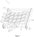
- the Figure 6 shows an exemplary design of the test piece magazine 5 in detail.
- the test piece magazine 5 comprises a plurality of test piece locations, each of which can accommodate a solid test piece.
- the test piece locations are arranged in an exemplary manner distributed in an xy plane.
- each test piece location is provided by a respective test piece carrier 16.
- the test piece magazine 5 expediently comprises a plurality of test piece carriers 16, which are arranged in an exemplary manner distributed in an xy plane.
- at least 5, in particular at least 10 or at least 15 test piece locations and/or test piece carriers 16 are present.
- only the front test piece carriers 16 are provided with the reference symbol "16" in the figures.
- Each test piece carrier 16 serves to hold one, in particular only one, test piece solid body 1.
- the test piece carriers 16 are designed as transport baskets by way of example.
- a plurality of solid-state test pieces 1 produced by means of additive manufacturing are arranged in the test piece magazine 5.
- the solid-state test pieces 1 are, for example, workpieces.
- the solid test pieces 1 have, for example, a cubic, spherical or hemispherical basic shape.
- the solid test pieces 1 can also have any basic shape.
- Each test piece carrier 16 expediently comprises a receiving area 17 for receiving a test piece solid body 1.
- the receiving area 17 is designed as Receiving chamber, in particular designed as a cylindrical receiving chamber.
- Each test piece carrier 16 comprises, for example, a carrier plate 55, which is aligned with its plate plane in particular perpendicular to the z-direction.
- In each carrier plate 55 there is an exemplary circular opening which exposes the receiving area 17, in particular the receiving chamber.
- Each receiving area 17 is expediently delimited laterally by a pipe section 56 which extends downwards from the carrier plate 55.
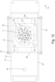
- the receiving area 17 is delimited at the bottom by a carrier base 57, which is designed in an exemplary circular manner.
- In the carrier base 57 there are one or more carrier base openings 58.
- the carrier base openings 58 are in particular in the Figure 12 can be seen.
- the carrier base openings 58 comprise several radially extending slot-shaped openings as well as a centrally arranged opening.
- the slot-shaped openings are arranged at equal angular intervals and expediently each run to the outer edge of the carrier base 57.
- the longitudinal axes of the slot-shaped openings expediently meet at the center of the centrally arranged opening.
- each test piece carrier 16 has two engagement structures 59, which are expediently designed as lateral recesses in the carrier plate 55.
- the engagement structures 59 serve to be brought into engagement with the gripping elements 53.
- two fixing structures 61 are also present, which are exemplarily designed as openings in the carrier plate 55. are designed.
- the fixing structures 61 serve to be brought into engagement with, in particular, pin-shaped fixing elements of the test piece magazine 5 in order to be fixed in a rotational manner (about a vertical axis of rotation) so that the test piece carrier 16 does not rotate with the gripping elements 53 during the gripping movement of the gripper 47, in which the gripping elements 53 are brought into engagement with the engagement structures 59.
- the test piece magazine 5 comprises, for example, a receiving section 62 for receiving the test piece carriers 16.
- the receiving section 62 is designed in particular as a tray.
- the top of the receiving section 62 represents an x-y receiving plane (aligned perpendicular to the z-direction) in which the test piece carriers 16 are arranged offset from one another in the x-direction and/or y-direction; in other words, they do not overlap in the x-direction and y-direction.
- the pin-shaped fixing elements are expediently arranged on the top of the receiving section 62.
- the test piece magazine 5 further comprises a pull-out 63 with which the receiving section 62 can be moved out of the working space 8, in particular through the loading opening 44.
- the pull-out 63 expediently enables the receiving section 62 to be moved in the y-direction.
- the pull-out 63 expediently comprises two pull-out rails 64 arranged parallel to one another, which are aligned in particular parallel to the y-direction.
- the receiving section 62 is expediently arranged between the two pull-out rails 64.
- the test piece magazine 5 further comprises a handle 65 with which the receiving section 62 can be moved by a user can be actuated to move the receiving section 62 by means of the extension 63.
- the handle 65 is arranged, for example, in the y-direction in front of the receiving section 62 and expediently in the x-direction centrally to the receiving section 62.
- the wet weighing device 4 will be discussed in more detail below.
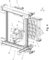
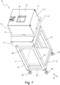
- the measuring machine 10 comprises a wet scale structure 15, which comprises the wet scale device 4 and a vibration damping suspension 9.
- the wet scale structure 15 is particularly suitable for Figures 7 and 8th shown.
- the wet scale device 4 stands on the vibration damping suspension 9.
- the vibration damping suspension 9 expediently stands on the same floor as the frame structure 11 and/or the measuring machine 10.
- the vibration damping suspension 9 is designed as a frame.
- the vibration damping suspension 9 comprises, as an example, a frame base 66 from which several vertical frame sections 67 extend vertically upwards.
- the vertical frame sections 67 carry a frame platform 68.
- the vibration damping suspension 9 also comprises several frame feet 69 with which the vibration damping suspension 9 stands on the floor.
- the vibration damping suspension 9 is arranged (at least partially) in the supply room 45 as an example.
- the vibration damping suspension 9 expediently comprises at least one vibration damping mass 71.
- the vibration damping suspension 9 comprises an upper vibration damping mass 72 and/or a lower vibration damping mass 73.
- the vibration damping masses 71 are expediently each as a weight plate, preferably as a stone plate, in particular a granite plate, and/or as a steel plate.
- the vibration damping masses 71 expediently have a density of at least 2 g/cm ⁇ 3, preferably of at least 7 g/cm ⁇ 3.
- the upper vibration damping mass 72 is expediently arranged between the frame platform 68 and the wet scale device 4.
- the wet scale device 4 stands on the upper vibration damping mass 72 and the upper vibration damping mass 72 rests on the frame platform 68.
- the lower vibration damping mass 73 is exemplarily arranged on the frame base 66.
- the vibration damping suspension 9 is designed to dampen mechanical vibrations originating from the environment of the measuring machine 10 in order to reduce their influence on the weighing measurements.
- the damping of the vibrations is achieved in particular by means of the at least one vibration damping mass 71.
- the vibration damping suspension 9 expediently prevents vibrations of the floor on which the frame structure 11 and the vibration damping suspension 9 stand from being transmitted to the wet weighing device 4.
- the vibration damping suspension 9 is designed in particular to dampen vibration frequencies of over 2 Hz, in particular in such a way that they do not influence the measurement with the wet weighing device 4.
- the wet weighing device 4 is in particular suspended differently than the dry weighing device 3, the feed unit 6 and/or the test piece magazine 5. While the test piece magazine 5, the feed unit 6 and expediently the dry weighing device 3 are, for example, suspended from the floor on which the measuring machine 10 stands, the frame structure 11, the wet scale device 4 is supported relative to the ground via the vibration damping suspension (and in particular not via the frame structure 11). The wet scale device 4 and in particular the vibration damping suspension 9 are expediently vibration-decoupled from the frame structure 11.
- the work space floor 12 on which the test piece magazine 5 stands comprises a wet scale recess 14, in particular an opening.
- the wet scale structure 15 extends through the wet scale recess 14.
- the wet scale structure 15 expediently extends through the wet scale recess 14 from the supply space 45 into the work space 8.
- the wet weighing device 4 expediently comprises a basin 21 in which a liquid 19, in particular water, is present.
- the liquid 19 can also be ethanol or another liquid.
- the density of the liquid 19 is expediently lower than the density of the solid test pieces 1.
- the solid test piece 1 is expediently immersed in the liquid 19 in the basin 21, in particular completely.
- a surfactant is mixed into the liquid 19, in particular the water.
- the surfactant can reduce, in particular prevent, the formation of bubbles in the liquid 19, whereby the accuracy of the measurement can be increased.
- the surfactant is expediently silicone-free.
- the surfactant is preferably a mixture of a wetting agent and a defoamer.
- the liquid 19, in particular the water comprises a wetting agent, in particular a silicone-free substrate wetting agent, expediently in a concentration of 0.2% by volume.
- the substrate wetting agent expediently comprises alcohol alkoxylates or consists thereof.
- the wetting agent is, for example, BYK-DYNWET 800 N from BYK.
- the measuring machine 10 is expediently designed to change the liquid 19 automatically, for example time- and/or measurement number-controlled.
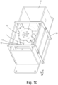
- the wet weighing device 4 optionally further comprises a cover 74 for covering the basin 21.
- the cover 74 is preferably a cover hood.
- the cover has a cuboid basic shape with an open underside in particular.
- the cover 74 comprises a cover upper side 75, in which there is expediently a carrier opening 76 through which a test piece carrier 16 can be lowered into the basin 21.
- the carrier opening 76 expediently takes up less than a third of the area of the cover upper side 75.
- the cover 74 comprises, for example, closed cover peripheral walls 77.
- the cover 74 is expediently put over the basin 21.
- the cover 74 is preferably put over the basin 21, a force transmission structure 23 and a first weighing unit 22.
- the cover 74 serves as an additional housing for the wet weighing device 4 (in addition to the peripheral walls of the automatic measuring device housing 7) and expediently prevents air movements from setting the liquid 19 in the basin 21 in motion and thereby disturbing the measurement.
- the wet scale device 4 comprises the first scale unit 22, which is designed as a laboratory precision scale, for example.
- the wet scale device 4 further comprises, for example, a basin support structure 77 that supports the basin 21.
- the first scale unit 22 and the basin support structure 77 expediently stand on the same base, for example on a wet scale base 78, in particular a plate-shaped wet scale base.
- the wet scale base 78 stands, for example, on the upper vibration damping mass 72.
- the first scale unit 22 comprises a first force absorption section and is designed to detect the force exerted on the first force absorption section and to provide a weighing measurement value, in particular the wet weighing measurement value, on the basis of the detected force.
- the force absorption section is arranged in particular on the top of the first scale unit 22.
- the force transmission structure 23 runs, for example, from the interior of the basin 21 to the force absorption section.
- the basin support structure 77 runs, for example, over the top of the first weighing unit 22, in particular over the force absorption section.
- the basin support structure 77 expediently comprises a basin support plate 79 on which the basin 21 stands and which runs over the first weighing unit 21, in particular over the force absorption section.
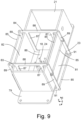
- the Figure 9 shows an exemplary design of the basin 21 and the force transmission structure 23 in detail.
- the basin 21 is designed as a cuboid and expediently has an open top.
- the force transmission structure 23 can also be referred to as a skeleton.
- the force transmission structure 23 leads, for example, from the interior of the basin 21, in particular from the liquid 19, out of the open top of the basin 21 and then leads downwards, expediently to below the basin 21, in particular to below the Basin support plate 79.
- the force transmission structure 23 comprises in particular a first closed contour 83 which runs from the interior of the basin 21, in particular from the liquid 19, out of the open upper side of the basin 21, then along a first basin peripheral wall 81 downwards to below the basin 21, in particular below the basin support plate 79, then runs under the basin 21, in particular under the basin support plate 79 and runs along a second basin peripheral wall 82 arranged parallel to the first basin peripheral wall 81 upwards and through the open upper side of the basin 21 into the basin 21, in particular the liquid 19.
- the force transmission structure 23 expediently further comprises a second closed contour 84, which is expediently designed to correspond to the first closed contour 83 and which is expediently arranged offset horizontally, in particular offset in the y-direction, to the first closed contour 83.
- the first closed contour 83 and the second closed contour 84 are connected to one another, for example, via rod-shaped connecting elements 85, which run in particular parallel to the x-direction.
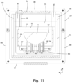
- the power transmission structure 23 is particularly in the Figure 11 can be seen.
- the force transmission structure 23, in particular the first closed contour 83 comprises, for example, a structural base 86, which is located in particular in the basin 21 in the liquid 19.
- a first test piece lifting structure 24 extends upwards from the structural base 86, which is also located in the liquid 19 in the basin 21.
- inner vertical sections 87 extend vertically upwards from the structural base 86, namely at least one inner vertical section 87 along the inside of the first Peripheral basin wall 81 and at least one inner vertical section 87 along the inside of the second peripheral basin wall 82.
- two inner vertical sections 87 are connected to one another via an upper horizontal section 88, which expediently runs above the basin 21.
- the inner vertical sections 87 protrude from the basin 21 and merge into outer vertical sections 89, which run vertically downwards outside the basin 21. At least one outer vertical section 89 runs downwards along the outside of the first peripheral basin wall 81 and at least one outer vertical section 89 runs downwards along the outside of the second peripheral basin wall 82. Two outer vertical sections 89 are connected via a lower horizontal section 91, which runs below the basin 21, in particular below the basin support plate 79. The lower horizontal section 91 is expediently coupled, in particular connected, to the force absorption section of the first scale unit 22.
- the force transmission structure 23 preferably weighs less than 120 g. Preferably, the force transmission structure 23 does not touch the basin 21.
- the force transmission structure 23 is partially located in the liquid 19, e.g. with the structure base 86 and the first test piece lifting structure 24.
- the first test piece lifting structure 24 is exemplarily designed as a pin bed.
- the first test piece lifting structure 24 expediently comprises a plurality of first pins 92, which expediently extend vertically upward from the structure base 86.
- the measuring machine 10 is expediently designed to carry out the weighing of each solid test piece 1 using the wet weighing device 4 in a state in which the solid test piece 1 is located within the receiving area 17 of the respective test piece carrier 16.
- the first test piece lifting structure 24 serves to reach into the respective test piece carrier 16 when weighing a solid test piece 1 and to lift the solid test piece 1 relative to the test piece carrier 16.
- the Figure 11 shows a state in which the test piece carrier 16 with a solid test piece 1 has been lowered from the feed unit 6 into the liquid 19 in the basin 21.
- the test piece carrier 16 and the solid test piece 1 are, for example, completely in the liquid 19.
- the measuring machine 10 is designed to carry out the weighing with the wet weighing device 4 in this state in order to obtain the wet weighing measurement value.
- the first test piece lifting structure 24, in particular the pins 92 reach through the carrier base openings 58 into the receiving area 17 and support the solid test piece 1, so that the solid test piece 1 is raised relative to the test piece carrier 16, in particular the carrier base 57, and in particular is no longer supported by the test piece carrier 16.
- the pins 92 expediently penetrate through the carrier floor openings 58 into the receiving area 17 so that the solid test piece rests on the pins 92 and is not lowered further (with the test piece carrier 16).
- the measuring machine 10 comprises a liquid level control device 25 for controlling the liquid level of the basin 21.
- the liquid level control device 25 expediently comprises the liquid container 46.
- the liquid level control device 25 further comprises a liquid feed device, a liquid level sensor device and/or a basin drain.
- the liquid feed device preferably comprises a pump, in particular a micro gear ring pump, in order to feed the liquid 19 to the basin 21, in particular from the liquid container 46.
- the liquid level control device 25 is designed to use the liquid level sensor device to detect the actual liquid level in the basin 21 and to regulate the liquid level on the basis of the actual liquid level and a target liquid level, in particular using the liquid feed device, in particular the micro gear ring pump.
- the liquid level control device 25 is designed to regulate the liquid level bubble-free, in particular by means of the micro gear ring pump.
- the measuring machine 10 is expediently designed to weigh the solid test piece 1 with the wet weighing device 4 by immersing the solid test piece 1 together with a/the respective test piece carrier 16 into the liquid 19 of the basin 21 and, after immersing the test piece carrier 16, to carry out the control of the liquid level, in particular by means of the liquid level control device 25.
- the measuring machine 10 is in particular designed to carry out the control of the liquid level before the wet weighing measurement value is recorded.
- the measuring device 10 is expediently designed to compensate by this control of the liquid level that the test piece carrier 16 and/or the gripper 47 change the liquid level when immersed in the liquid 19 in the basin 21 and thereby influence the wet weighing measurement value.
- the dry weighing device 3 comprises a second weighing unit 93, which is designed as a laboratory precision balance by way of example.
- the second weighing unit 93 comprises a second force-absorbing section 94 and is designed to detect the force exerted on the second force-absorbing section 94 and to provide a weighing measurement value, in particular a dry weighing measurement value, based on the detected force.
- the second force-absorbing section 94 is arranged in particular on the top side of the second weighing unit 93.
- a second test piece lifting structure 95 is arranged by way of example on the second force-absorbing section 94.
- the second test piece lifting structure 95 is designed as a pin bed by way of example.
- the second test piece lifting structure 95 expediently comprises a second structural base 96, which is in particular plate-shaped, and a plurality of second pins 97, which expediently extend vertically upwards from the second structural base 96.
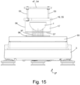
- the measuring machine 10 is expediently designed to carry out the weighing of each solid test piece 1 using the dry balance device 3 in a state in which the solid test piece 1 is located within the receiving area 17 of the respective test piece carrier 16.
- the second test piece lifting structure 95 is designed to be placed in the to grasp the respective test piece carrier 16 and to lift the solid test piece 1 relative to the test piece carrier 16.
- the Figure 15 shows a state in which the test piece carrier 16 with a solid test piece 1 has been lowered from the feed unit 6 onto the second test piece lifting structure 95.
- the measuring machine 10 is designed to carry out the weighing with the dry weighing device 3 in this state in order to obtain the dry weighing measurement value.
- the second test piece lifting structure 95 in particular the pins 97, reach through the carrier base openings 58 into the receiving area 17 and support the solid test piece 1, so that the solid test piece 1 is raised relative to the test piece carrier 16, in particular the carrier base 57, and in particular is no longer supported by the test piece carrier 16.
- the pins 92 expediently penetrate through the carrier base openings 58 into the receiving area 17 so that the solid test piece 1 rests on the pins 92 and is not lowered further (with the test piece carrier 16).
- the Figure 16 shows a production plant 20 that includes a production hall 27, for example a building hall.
- the production plant 20 is in particular an industrial production plant.
- the production plant 20 includes an automatic measuring device 10, which is expediently designed as described here.
- the production plant 20 also includes a production device 28 for producing solid-state test pieces 1, for example workpieces.
- the production device 28 is designed, for example, to produce the solid-state test pieces 1 by additive manufacturing.
- the production device 28 includes a 3D printer for producing the solid-state test pieces 1.
- the production device 28 and the measuring machine 10 are expediently located on the same floor, in particular the floor of the production hall 27.
- the production plant 20 preferably further comprises a loading unit 98 for loading the solid-state test pieces 1 produced with the production device 28 into the measuring machine 10.
- the loading unit is, for example, a robot unit.
- the measuring machine 10 is expediently designed to record weighing measurements, in particular a wet weighing measurement and a dry weighing measurement, for each solid test piece 1.
- the measuring machine 10 is expediently further designed to assess a manufacturing quality of the solid test pieces 1 on the basis of the weighing measurements and to provide corresponding assessment information.
- the production device 28 is designed to adapt the production of the solid-state test pieces on the basis of the assessment information. For example, there is a communication connection between the measuring machine 10 and the production device 28, via which the assessment information is transmitted.
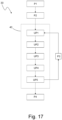
- the Figure 17 shows a flow chart of a method 30 according to which the measuring machine can be operated.
- the method 30 can also be referred to as a measuring procedure.
- the measuring machine 10 expediently comprises a control unit, in particular a computer unit, for example a microcontroller, which controls the operation and in particular the steps explained below.
- the control unit is designed to control the automated operation of the measuring machine 10.
- the control unit is expediently designed to control the feed unit 6 in order to bring about the feeding of the solid test pieces 1.
- the control unit is expediently designed to control the liquid level control device 25 in order to achieve a control of the liquid level.
- the control unit is designed to communicate with the dry weighing device 3 and the wet weighing device 4 in order to expediently read out the dry weighing measurement value and the wet weighing measurement value.
- the control unit is also expediently designed to calculate the density value on the basis of the dry weighing measurement value and the wet weighing measurement value.
- step P1 in which several solid-state test pieces 1 are loaded into the measuring machine 10, in particular into the test piece magazine 5.
- the receiving section 62 is manually pulled out of the work space 8 through the loading opening 44 using the handle 65 and the solid-state test pieces 1 are loaded into the test piece locations, in particular the test piece carriers 16.
- loading is carried out automatically. It is also possible for loading to take place by conveying a receiving section 62 already loaded with solid-state test pieces 1 into the measuring machine 10, in particular in an automated manner.
- step P2 in which the measuring machine 10 is provided with selection information is provided which indicates one or more test piece locations of the test piece magazine 5.
- the measuring machine 10 is designed to determine the density for those solid test pieces 1 which are located at the test piece locations determined by the selection information.
- the selection information is entered by means of a user input, in particular via the interface 26.
- the interface 26 shows a representation of the test piece locations (for example a checkerboard pattern) and the user can select those test piece locations for which a density determination is to be carried out by touching the test piece locations shown.
- the measuring machine 10 is designed to automatically detect at which test piece locations a solid-state test piece is arranged, for example by means of an optical sensor system.
- Step P2 can expediently also be carried out before step P1 or parallel to step P1.
- the method 30 continues with a measuring sub-procedure 40.
- the measuring machine 10 is expediently designed to carry out a separate measuring sub-procedure 40 for each solid test piece (for which a density determination is to be carried out).
- the measuring sub-procedure 40 comprises the step UP1, in which the feed unit 6 picks up a first test piece carrier 16.
- the measuring machine 10 is expediently designed to pick up the first test piece carrier 16 automatically by means of the feed unit 6, for example by automatically moving the gripper 47 to the first test piece carrier 16 is brought into engagement with the first test piece carrier 16, for example by carrying out the gripping movement, and the test piece carrier 16 is then lifted out of the test piece magazine 5, in particular from the receiving section 62.
- the measuring sub-procedure 40 further comprises the step UP2, in which the first solid test piece 1 located in the first test piece carrier 16 is weighed with the dry scale device 3.
- the measuring machine 10 is expediently designed to move the first solid test piece 1 in the first test piece carrier 16 to the dry scale device 3 by means of the feed unit 6, expediently by moving the gripper 47 in an x-direction and/or a y-direction.
- the measuring machine 10 is further expediently designed to lower the first test piece carrier 16 onto the dry scale device 3 by means of the feed unit 6.
- the second test piece lifting structure 95 expediently engages the receiving area 17 of the first test piece carrier 16 and lifts the first solid test piece 1 relative to the first test piece carrier 16.
- the force exerted by the first solid test piece 1 on the second test piece lifting structure 95 is transmitted to the second force receiving section 94 and recorded by the second weighing unit 93 as a dry weighing measurement value.
- the measuring sub-procedure 40 further comprises the step UP3, in which the first solid test piece 1 located in the first test piece carrier 16 is weighed with the wet weighing device 4.
- the measuring machine 10 is expediently designed to move the first solid test piece 1 in the first test piece carrier 16 by means of the feed unit 6 to the wet weighing device 4, expediently by a movement of the gripper 47 in an x-direction and/or a y-direction.
- the measuring machine 10 is expediently further designed to lower the first test piece carrier 16 into the basin 21, in particular the liquid 19, by means of the feed unit 6.
- the first test piece lifting structure 24 When the first test piece carrier 16 is lowered, the first test piece lifting structure 24 expediently grips the receiving area of the first test piece carrier 16 and lifts the first solid test piece 1 relative to the first test piece carrier 16. The force exerted by the first solid test piece 1 on the first test piece lifting structure 24 is transmitted to the first force receiving section via the force transmission structure 23 and recorded by the first weighing unit 22 as a wet weighing measurement value.
- the measuring machine 10 is expediently designed to regulate the liquid level of the basin 21 after the first test piece carrier 16 has been immersed in the liquid 19.
- the liquid level is expediently regulated before the wet weighing measurement value is recorded.
- the liquid level is regulated before the first solid test piece 1 is lowered onto the first test piece lifting structure 24.
- the measuring machine 10 is expediently designed to zero the first weighing unit 22 after the liquid level has been regulated and before the first solid test piece 1 is lowered onto the first test piece lifting structure 24.
- the measuring sub-procedure 40 further comprises the step UP4, in which the density value of the first solid test piece 1 is calculated on the basis of the dry weighing measurement value and the wet weighing measurement value.
- the measuring machine 10 is designed to calculate the density value according to the Archimedean principle
- the measuring machine 10 expediently provides the calculated density value as density information.
- the measuring sub-procedure 40 further comprises the step UP5, in which the feed unit 6 places the first test piece carrier 16 back into the test piece magazine 5.
- the measuring machine 10 is expediently designed to automatically place the first test piece carrier 16 back into the test piece magazine 5 by means of the feed unit 6, for example by automatically moving the gripper 47 to the test piece magazine 5, lowering the first test piece carrier 16 into the receiving section 62 and releasing the engagement with the first test piece carrier 16, in particular by a rotary movement of the gripper 47.
- Step UP5 can also conveniently be carried out before step UP4 or parallel to step UP4.
- the measuring machine 10 is expediently designed to carry out the steps of the measuring sub-procedure 40 fully automatically - i.e. without user intervention.
- the measuring machine 10 is expediently designed to carry out the measuring sub-procedure for a solid test piece 1 in two minutes or less.
- step P3 the measuring machine 10 selects the next (second) solid test piece 1 to be measured.
- the method then carries out a further measuring sub-procedure 40, namely for a second test piece carrier 16 in which the next (second) solid test piece 1 to be measured is located.
- the measuring machine 10 is expediently designed to repeat the measuring sub-procedure 40 for further Solid test pieces 1 until the density has been determined for all solid test pieces 1 stored in the solid magazine 5 and/or for all solid test pieces 1 indicated by the selection information.
- step P4 in which the method 30 is terminated.
- the solid test pieces 1 are removed from the measuring machine 10 and/or sorted, in particular automated, according to the density values obtained.
Landscapes
- Physics & Mathematics (AREA)
- Health & Medical Sciences (AREA)
- Life Sciences & Earth Sciences (AREA)
- Chemical & Material Sciences (AREA)
- Analytical Chemistry (AREA)
- Biochemistry (AREA)
- General Health & Medical Sciences (AREA)
- General Physics & Mathematics (AREA)
- Immunology (AREA)
- Pathology (AREA)
- Sampling And Sample Adjustment (AREA)
Applications Claiming Priority (2)
| Application Number | Priority Date | Filing Date | Title |
|---|---|---|---|
| DE102019215936.2A DE102019215936A1 (de) | 2019-10-16 | 2019-10-16 | Messautomat, Fertigungsanlage und Verfahren |
| PCT/EP2020/079260 WO2021074410A1 (de) | 2019-10-16 | 2020-10-16 | Messautomat, fertigungsanlage und verfahren |
Publications (3)
| Publication Number | Publication Date |
|---|---|
| EP4045889A1 EP4045889A1 (de) | 2022-08-24 |
| EP4045889C0 EP4045889C0 (de) | 2024-06-26 |
| EP4045889B1 true EP4045889B1 (de) | 2024-06-26 |
Family
ID=73030079
Family Applications (1)
| Application Number | Title | Priority Date | Filing Date |
|---|---|---|---|
| EP20797688.7A Active EP4045889B1 (de) | 2019-10-16 | 2020-10-16 | Messautomat, fertigungsanlage und verfahren |
Country Status (10)
| Country | Link |
|---|---|
| US (1) | US12399096B2 (ja) |
| EP (1) | EP4045889B1 (ja) |
| JP (1) | JP7650876B2 (ja) |
| KR (1) | KR20220079895A (ja) |
| CN (1) | CN114761784B (ja) |
| BR (1) | BR112022007153A2 (ja) |
| CA (1) | CA3157894A1 (ja) |
| DE (1) | DE102019215936A1 (ja) |
| MX (1) | MX2022004460A (ja) |
| WO (1) | WO2021074410A1 (ja) |
Families Citing this family (1)
| Publication number | Priority date | Publication date | Assignee | Title |
|---|---|---|---|---|
| DE102021115492A1 (de) | 2021-04-14 | 2022-10-20 | MTU Aero Engines AG | Verfahren zur charakterisierung einer beschichtung |
Family Cites Families (11)
| Publication number | Priority date | Publication date | Assignee | Title |
|---|---|---|---|---|
| GB1443789A (en) * | 1973-11-28 | 1976-07-28 | Monsanto Ltd | Apparatus for measuring specific gravity |
| GB9303887D0 (en) | 1993-02-26 | 1993-04-21 | British Nuclear Fuels Plc | An apparatus and a method for automatically measuring the density of an object |
| DE19911859A1 (de) * | 1999-03-17 | 2000-09-21 | Mettler Toledo Gmbh | Waage |
| DE19919011A1 (de) * | 1999-04-27 | 2000-11-02 | Mettler Toledo Gmbh | Flüssigkeit zum Messen der Dichte von Körpern |
| KR100764065B1 (ko) * | 2006-03-24 | 2007-10-11 | 주식회사 나노하이테크 | 고체밀도 자동측정기 및 방법 |
| KR200419207Y1 (ko) * | 2006-03-28 | 2006-06-19 | 주식회사 나노하이테크 | 고체밀도 자동측정기 |
| JP5331076B2 (ja) | 2010-09-21 | 2013-10-30 | Jx日鉱日石エネルギー株式会社 | 浸せき試験用自動測定装置 |
| DE102015007648A1 (de) * | 2015-06-17 | 2016-12-22 | DB Sediments GmbH | Verfahren und Vorrichtung zur Bestimmung des Gewichtes von einem Messvolumen einer Wasser-Feststoff-Mischung und/oder der Dichte einer Wasser-Feststoff-Mischung |
| CN206832619U (zh) * | 2017-04-17 | 2018-01-02 | 杭州安费诺飞凤通信部品有限公司 | 一种自动化密度测试设备 |
| CN108861543B (zh) * | 2018-06-28 | 2021-02-09 | 格力电器(武汉)有限公司 | 一种上下料系统及方法 |
| CN109883881B (zh) * | 2019-04-02 | 2024-02-13 | 中国工程物理研究院化工材料研究所 | 一种称重装置、pbx炸药柱自动密度测试仪及其测试方法 |
-
2019
- 2019-10-16 DE DE102019215936.2A patent/DE102019215936A1/de not_active Ceased
-
2020
- 2020-10-16 MX MX2022004460A patent/MX2022004460A/es unknown
- 2020-10-16 US US17/769,537 patent/US12399096B2/en active Active
- 2020-10-16 KR KR1020227014795A patent/KR20220079895A/ko not_active Ceased
- 2020-10-16 BR BR112022007153A patent/BR112022007153A2/pt not_active Application Discontinuation
- 2020-10-16 CN CN202080087245.6A patent/CN114761784B/zh active Active
- 2020-10-16 CA CA3157894A patent/CA3157894A1/en active Pending
- 2020-10-16 JP JP2022523092A patent/JP7650876B2/ja active Active
- 2020-10-16 EP EP20797688.7A patent/EP4045889B1/de active Active
- 2020-10-16 WO PCT/EP2020/079260 patent/WO2021074410A1/de not_active Ceased
Also Published As
| Publication number | Publication date |
|---|---|
| JP2022552565A (ja) | 2022-12-16 |
| EP4045889C0 (de) | 2024-06-26 |
| EP4045889A1 (de) | 2022-08-24 |
| CN114761784A (zh) | 2022-07-15 |
| KR20220079895A (ko) | 2022-06-14 |
| CN114761784B (zh) | 2026-02-03 |
| WO2021074410A1 (de) | 2021-04-22 |
| US12399096B2 (en) | 2025-08-26 |
| JP7650876B2 (ja) | 2025-03-25 |
| CA3157894A1 (en) | 2021-04-22 |
| US20230076189A1 (en) | 2023-03-09 |
| MX2022004460A (es) | 2022-06-08 |
| DE102019215936A1 (de) | 2021-04-22 |
| BR112022007153A2 (pt) | 2022-06-28 |
Similar Documents
| Publication | Publication Date | Title |
|---|---|---|
| EP1092473A2 (de) | Vorrichtung zur gravimetrischen Prüfung von Mehrkanalpipetten | |
| DE10246211A1 (de) | Labor-Arbeitsstation zum Bereitstellen von Proben | |
| EP1955009B1 (de) | Vorrichtung zum bestimmen einer messgrösse an einem messobjekt | |
| EP4045889B1 (de) | Messautomat, fertigungsanlage und verfahren | |
| EP0426095A2 (de) | Koordinatenmessgerät | |
| DE3826400C2 (ja) | ||
| EP0779506B1 (de) | Dissolutionstestgerät | |
| DE102019218683A1 (de) | Automatisches schraubeninspektionssystem | |
| EP3274669A1 (de) | Waage mit lastwechseleinrichtung und verfahren zu deren betrieb | |
| WO2009115204A1 (de) | Werkzeug-maschine mit beschickungs- und entnahme-vorrichtung | |
| DE19958306C2 (de) | Koordinatenmeßvorrichtung | |
| DE3419546A1 (de) | Einrichtung zur ermittlung der schwerpunktlage eines pruefkoerpers | |
| DE102022129566B4 (de) | Füllmaschine | |
| DE102022107331B3 (de) | Wägevorrichtung und Gewichtsmagazin dafür | |
| EP0567153B1 (de) | Ultraschallprüfvorrichtung | |
| EP1161667A1 (de) | Wägeeinrichtung zur dichtebestimmung | |
| DE202013008237U1 (de) | Maschinenbasis für Werkzeugeinstellgerät sowie Werkzeugeinstellgerät | |
| DE102006061222A1 (de) | Mikroplatten-Waschgerät mit integriertem Mikroplattentransport | |
| DE3248768A1 (de) | Mess- und bestueckungsgeraet fuer schneidkoepfe und schneidwalzen | |
| EP1571411A1 (de) | Messeinrichtung | |
| DE102005048578B4 (de) | Maschine mit einem positionsgenau verfahrbaren Kopf, insbesondere Koordinatenmessgerät | |
| DE102023133089A1 (de) | Probenaufbereitungseinrichtung mit einem Wasserbad | |
| DE202023107419U1 (de) | Vorrichtung zum Entladen, Laden und Handhaben von Zylindern | |
| DE2416246B2 (de) | Funkenerosions-Werkzeugmaschine | |
| WO2023117335A1 (de) | Bestimmung einer wiege- und wiederholgenauigkeit einer präzisionswaage |
Legal Events
| Date | Code | Title | Description |
|---|---|---|---|
| STAA | Information on the status of an ep patent application or granted ep patent |
Free format text: STATUS: UNKNOWN |
|
| STAA | Information on the status of an ep patent application or granted ep patent |
Free format text: STATUS: THE INTERNATIONAL PUBLICATION HAS BEEN MADE |
|
| PUAI | Public reference made under article 153(3) epc to a published international application that has entered the european phase |
Free format text: ORIGINAL CODE: 0009012 |
|
| STAA | Information on the status of an ep patent application or granted ep patent |
Free format text: STATUS: REQUEST FOR EXAMINATION WAS MADE |
|
| 17P | Request for examination filed |
Effective date: 20220512 |
|
| AK | Designated contracting states |
Kind code of ref document: A1 Designated state(s): AL AT BE BG CH CY CZ DE DK EE ES FI FR GB GR HR HU IE IS IT LI LT LU LV MC MK MT NL NO PL PT RO RS SE SI SK SM TR |
|
| DAV | Request for validation of the european patent (deleted) | ||
| DAX | Request for extension of the european patent (deleted) | ||
| GRAP | Despatch of communication of intention to grant a patent |
Free format text: ORIGINAL CODE: EPIDOSNIGR1 |
|
| STAA | Information on the status of an ep patent application or granted ep patent |
Free format text: STATUS: GRANT OF PATENT IS INTENDED |
|
| INTG | Intention to grant announced |
Effective date: 20240201 |
|
| GRAS | Grant fee paid |
Free format text: ORIGINAL CODE: EPIDOSNIGR3 |
|
| GRAA | (expected) grant |
Free format text: ORIGINAL CODE: 0009210 |
|
| STAA | Information on the status of an ep patent application or granted ep patent |
Free format text: STATUS: THE PATENT HAS BEEN GRANTED |
|
| AK | Designated contracting states |
Kind code of ref document: B1 Designated state(s): AL AT BE BG CH CY CZ DE DK EE ES FI FR GB GR HR HU IE IS IT LI LT LU LV MC MK MT NL NO PL PT RO RS SE SI SK SM TR |
|
| REG | Reference to a national code |
Ref country code: GB Ref legal event code: FG4D Free format text: NOT ENGLISH |
|
| REG | Reference to a national code |
Ref country code: CH Ref legal event code: EP |
|
| REG | Reference to a national code |
Ref country code: DE Ref legal event code: R096 Ref document number: 502020008393 Country of ref document: DE |
|
| U01 | Request for unitary effect filed |
Effective date: 20240712 |
|
| U07 | Unitary effect registered |
Designated state(s): AT BE BG DE DK EE FI FR IT LT LU LV MT NL PT SE SI Effective date: 20240726 |
|
| PG25 | Lapsed in a contracting state [announced via postgrant information from national office to epo] |
Ref country code: HR Free format text: LAPSE BECAUSE OF FAILURE TO SUBMIT A TRANSLATION OF THE DESCRIPTION OR TO PAY THE FEE WITHIN THE PRESCRIBED TIME-LIMIT Effective date: 20240626 |
|
| PG25 | Lapsed in a contracting state [announced via postgrant information from national office to epo] |
Ref country code: GR Free format text: LAPSE BECAUSE OF FAILURE TO SUBMIT A TRANSLATION OF THE DESCRIPTION OR TO PAY THE FEE WITHIN THE PRESCRIBED TIME-LIMIT Effective date: 20240927 |
|
| PG25 | Lapsed in a contracting state [announced via postgrant information from national office to epo] |
Ref country code: NO Free format text: LAPSE BECAUSE OF FAILURE TO SUBMIT A TRANSLATION OF THE DESCRIPTION OR TO PAY THE FEE WITHIN THE PRESCRIBED TIME-LIMIT Effective date: 20240926 Ref country code: HR Free format text: LAPSE BECAUSE OF FAILURE TO SUBMIT A TRANSLATION OF THE DESCRIPTION OR TO PAY THE FEE WITHIN THE PRESCRIBED TIME-LIMIT Effective date: 20240626 Ref country code: GR Free format text: LAPSE BECAUSE OF FAILURE TO SUBMIT A TRANSLATION OF THE DESCRIPTION OR TO PAY THE FEE WITHIN THE PRESCRIBED TIME-LIMIT Effective date: 20240927 Ref country code: RS Free format text: LAPSE BECAUSE OF FAILURE TO SUBMIT A TRANSLATION OF THE DESCRIPTION OR TO PAY THE FEE WITHIN THE PRESCRIBED TIME-LIMIT Effective date: 20240926 |
|
| U20 | Renewal fee for the european patent with unitary effect paid |
Year of fee payment: 5 Effective date: 20241025 |
|
| PG25 | Lapsed in a contracting state [announced via postgrant information from national office to epo] |
Ref country code: PL Free format text: LAPSE BECAUSE OF FAILURE TO SUBMIT A TRANSLATION OF THE DESCRIPTION OR TO PAY THE FEE WITHIN THE PRESCRIBED TIME-LIMIT Effective date: 20240626 |
|
| PG25 | Lapsed in a contracting state [announced via postgrant information from national office to epo] |
Ref country code: IS Free format text: LAPSE BECAUSE OF FAILURE TO SUBMIT A TRANSLATION OF THE DESCRIPTION OR TO PAY THE FEE WITHIN THE PRESCRIBED TIME-LIMIT Effective date: 20241026 |
|
| PG25 | Lapsed in a contracting state [announced via postgrant information from national office to epo] |
Ref country code: CZ Free format text: LAPSE BECAUSE OF FAILURE TO SUBMIT A TRANSLATION OF THE DESCRIPTION OR TO PAY THE FEE WITHIN THE PRESCRIBED TIME-LIMIT Effective date: 20240626 |
|
| PG25 | Lapsed in a contracting state [announced via postgrant information from national office to epo] |
Ref country code: SK Free format text: LAPSE BECAUSE OF FAILURE TO SUBMIT A TRANSLATION OF THE DESCRIPTION OR TO PAY THE FEE WITHIN THE PRESCRIBED TIME-LIMIT Effective date: 20240626 Ref country code: RO Free format text: LAPSE BECAUSE OF FAILURE TO SUBMIT A TRANSLATION OF THE DESCRIPTION OR TO PAY THE FEE WITHIN THE PRESCRIBED TIME-LIMIT Effective date: 20240626 |
|
| PG25 | Lapsed in a contracting state [announced via postgrant information from national office to epo] |
Ref country code: ES Free format text: LAPSE BECAUSE OF FAILURE TO SUBMIT A TRANSLATION OF THE DESCRIPTION OR TO PAY THE FEE WITHIN THE PRESCRIBED TIME-LIMIT Effective date: 20240626 Ref country code: SM Free format text: LAPSE BECAUSE OF FAILURE TO SUBMIT A TRANSLATION OF THE DESCRIPTION OR TO PAY THE FEE WITHIN THE PRESCRIBED TIME-LIMIT Effective date: 20240626 |
|
| PG25 | Lapsed in a contracting state [announced via postgrant information from national office to epo] |
Ref country code: SM Free format text: LAPSE BECAUSE OF FAILURE TO SUBMIT A TRANSLATION OF THE DESCRIPTION OR TO PAY THE FEE WITHIN THE PRESCRIBED TIME-LIMIT Effective date: 20240626 Ref country code: SK Free format text: LAPSE BECAUSE OF FAILURE TO SUBMIT A TRANSLATION OF THE DESCRIPTION OR TO PAY THE FEE WITHIN THE PRESCRIBED TIME-LIMIT Effective date: 20240626 Ref country code: RO Free format text: LAPSE BECAUSE OF FAILURE TO SUBMIT A TRANSLATION OF THE DESCRIPTION OR TO PAY THE FEE WITHIN THE PRESCRIBED TIME-LIMIT Effective date: 20240626 Ref country code: PL Free format text: LAPSE BECAUSE OF FAILURE TO SUBMIT A TRANSLATION OF THE DESCRIPTION OR TO PAY THE FEE WITHIN THE PRESCRIBED TIME-LIMIT Effective date: 20240626 Ref country code: IS Free format text: LAPSE BECAUSE OF FAILURE TO SUBMIT A TRANSLATION OF THE DESCRIPTION OR TO PAY THE FEE WITHIN THE PRESCRIBED TIME-LIMIT Effective date: 20241026 Ref country code: ES Free format text: LAPSE BECAUSE OF FAILURE TO SUBMIT A TRANSLATION OF THE DESCRIPTION OR TO PAY THE FEE WITHIN THE PRESCRIBED TIME-LIMIT Effective date: 20240626 Ref country code: CZ Free format text: LAPSE BECAUSE OF FAILURE TO SUBMIT A TRANSLATION OF THE DESCRIPTION OR TO PAY THE FEE WITHIN THE PRESCRIBED TIME-LIMIT Effective date: 20240626 |
|
| PLBE | No opposition filed within time limit |
Free format text: ORIGINAL CODE: 0009261 |
|
| STAA | Information on the status of an ep patent application or granted ep patent |
Free format text: STATUS: NO OPPOSITION FILED WITHIN TIME LIMIT |
|
| REG | Reference to a national code |
Ref country code: CH Ref legal event code: PL |
|
| 26N | No opposition filed |
Effective date: 20250327 |
|
| GBPC | Gb: european patent ceased through non-payment of renewal fee |
Effective date: 20241016 |
|
| PG25 | Lapsed in a contracting state [announced via postgrant information from national office to epo] |
Ref country code: MC Free format text: LAPSE BECAUSE OF FAILURE TO SUBMIT A TRANSLATION OF THE DESCRIPTION OR TO PAY THE FEE WITHIN THE PRESCRIBED TIME-LIMIT Effective date: 20240626 |
|
| PG25 | Lapsed in a contracting state [announced via postgrant information from national office to epo] |
Ref country code: GB Free format text: LAPSE BECAUSE OF NON-PAYMENT OF DUE FEES Effective date: 20241016 |
|
| PG25 | Lapsed in a contracting state [announced via postgrant information from national office to epo] |
Ref country code: CH Free format text: LAPSE BECAUSE OF NON-PAYMENT OF DUE FEES Effective date: 20241031 |
|
| PG25 | Lapsed in a contracting state [announced via postgrant information from national office to epo] |
Ref country code: IE Free format text: LAPSE BECAUSE OF NON-PAYMENT OF DUE FEES Effective date: 20241016 |
|
| U20 | Renewal fee for the european patent with unitary effect paid |
Year of fee payment: 6 Effective date: 20251023 |
|
| PG25 | Lapsed in a contracting state [announced via postgrant information from national office to epo] |
Ref country code: CY Free format text: LAPSE BECAUSE OF FAILURE TO SUBMIT A TRANSLATION OF THE DESCRIPTION OR TO PAY THE FEE WITHIN THE PRESCRIBED TIME-LIMIT; INVALID AB INITIO Effective date: 20201016 |
|
| PG25 | Lapsed in a contracting state [announced via postgrant information from national office to epo] |
Ref country code: HU Free format text: LAPSE BECAUSE OF FAILURE TO SUBMIT A TRANSLATION OF THE DESCRIPTION OR TO PAY THE FEE WITHIN THE PRESCRIBED TIME-LIMIT; INVALID AB INITIO Effective date: 20201016 |