EP4045337B1 - Pneumatique a faible resistance au roulement et son procede de fabrication - Google Patents
Pneumatique a faible resistance au roulement et son procede de fabrication Download PDFInfo
- Publication number
- EP4045337B1 EP4045337B1 EP20797827.1A EP20797827A EP4045337B1 EP 4045337 B1 EP4045337 B1 EP 4045337B1 EP 20797827 A EP20797827 A EP 20797827A EP 4045337 B1 EP4045337 B1 EP 4045337B1
- Authority
- EP
- European Patent Office
- Prior art keywords
- hooping
- carcass
- assembly
- working
- reinforcement
- Prior art date
- Legal status (The legal status is an assumption and is not a legal conclusion. Google has not performed a legal analysis and makes no representation as to the accuracy of the status listed.)
- Active
Links
Images


Classifications
-
- B—PERFORMING OPERATIONS; TRANSPORTING
- B60—VEHICLES IN GENERAL
- B60C—VEHICLE TYRES; TYRE INFLATION; TYRE CHANGING; CONNECTING VALVES TO INFLATABLE ELASTIC BODIES IN GENERAL; DEVICES OR ARRANGEMENTS RELATED TO TYRES
- B60C9/00—Reinforcements or ply arrangement of pneumatic tyres
- B60C9/18—Structure or arrangement of belts or breakers, crown-reinforcing or cushioning layers
- B60C9/20—Structure or arrangement of belts or breakers, crown-reinforcing or cushioning layers built-up from rubberised plies each having all cords arranged substantially parallel
- B60C9/2003—Structure or arrangement of belts or breakers, crown-reinforcing or cushioning layers built-up from rubberised plies each having all cords arranged substantially parallel characterised by the materials of the belt cords
-
- B—PERFORMING OPERATIONS; TRANSPORTING
- B29—WORKING OF PLASTICS; WORKING OF SUBSTANCES IN A PLASTIC STATE IN GENERAL
- B29D—PRODUCING PARTICULAR ARTICLES FROM PLASTICS OR FROM SUBSTANCES IN A PLASTIC STATE
- B29D30/00—Producing pneumatic or solid tyres or parts thereof
- B29D30/06—Pneumatic tyres or parts thereof (e.g. produced by casting, moulding, compression moulding, injection moulding, centrifugal casting)
- B29D30/08—Building tyres
- B29D30/20—Building tyres by the flat-tyre method, i.e. building on cylindrical drums
-
- B—PERFORMING OPERATIONS; TRANSPORTING
- B60—VEHICLES IN GENERAL
- B60C—VEHICLE TYRES; TYRE INFLATION; TYRE CHANGING; CONNECTING VALVES TO INFLATABLE ELASTIC BODIES IN GENERAL; DEVICES OR ARRANGEMENTS RELATED TO TYRES
- B60C9/00—Reinforcements or ply arrangement of pneumatic tyres
- B60C9/0042—Reinforcements made of synthetic materials
-
- B—PERFORMING OPERATIONS; TRANSPORTING
- B60—VEHICLES IN GENERAL
- B60C—VEHICLE TYRES; TYRE INFLATION; TYRE CHANGING; CONNECTING VALVES TO INFLATABLE ELASTIC BODIES IN GENERAL; DEVICES OR ARRANGEMENTS RELATED TO TYRES
- B60C9/00—Reinforcements or ply arrangement of pneumatic tyres
- B60C9/005—Reinforcements made of different materials, e.g. hybrid or composite cords
-
- B—PERFORMING OPERATIONS; TRANSPORTING
- B60—VEHICLES IN GENERAL
- B60C—VEHICLE TYRES; TYRE INFLATION; TYRE CHANGING; CONNECTING VALVES TO INFLATABLE ELASTIC BODIES IN GENERAL; DEVICES OR ARRANGEMENTS RELATED TO TYRES
- B60C9/00—Reinforcements or ply arrangement of pneumatic tyres
- B60C9/18—Structure or arrangement of belts or breakers, crown-reinforcing or cushioning layers
- B60C9/20—Structure or arrangement of belts or breakers, crown-reinforcing or cushioning layers built-up from rubberised plies each having all cords arranged substantially parallel
- B60C9/22—Structure or arrangement of belts or breakers, crown-reinforcing or cushioning layers built-up from rubberised plies each having all cords arranged substantially parallel the plies being arranged with all cords disposed along the circumference of the tyre
- B60C9/2204—Structure or arrangement of belts or breakers, crown-reinforcing or cushioning layers built-up from rubberised plies each having all cords arranged substantially parallel the plies being arranged with all cords disposed along the circumference of the tyre obtained by circumferentially narrow strip winding
-
- B—PERFORMING OPERATIONS; TRANSPORTING
- B60—VEHICLES IN GENERAL
- B60C—VEHICLE TYRES; TYRE INFLATION; TYRE CHANGING; CONNECTING VALVES TO INFLATABLE ELASTIC BODIES IN GENERAL; DEVICES OR ARRANGEMENTS RELATED TO TYRES
- B60C9/00—Reinforcements or ply arrangement of pneumatic tyres
- B60C9/18—Structure or arrangement of belts or breakers, crown-reinforcing or cushioning layers
- B60C9/20—Structure or arrangement of belts or breakers, crown-reinforcing or cushioning layers built-up from rubberised plies each having all cords arranged substantially parallel
- B60C2009/2074—Physical properties or dimension of the belt cord
- B60C2009/2093—Elongation of the reinforcements at break point
-
- B—PERFORMING OPERATIONS; TRANSPORTING
- B60—VEHICLES IN GENERAL
- B60C—VEHICLE TYRES; TYRE INFLATION; TYRE CHANGING; CONNECTING VALVES TO INFLATABLE ELASTIC BODIES IN GENERAL; DEVICES OR ARRANGEMENTS RELATED TO TYRES
- B60C9/00—Reinforcements or ply arrangement of pneumatic tyres
- B60C9/18—Structure or arrangement of belts or breakers, crown-reinforcing or cushioning layers
- B60C9/20—Structure or arrangement of belts or breakers, crown-reinforcing or cushioning layers built-up from rubberised plies each having all cords arranged substantially parallel
- B60C9/22—Structure or arrangement of belts or breakers, crown-reinforcing or cushioning layers built-up from rubberised plies each having all cords arranged substantially parallel the plies being arranged with all cords disposed along the circumference of the tyre
- B60C2009/2214—Structure or arrangement of belts or breakers, crown-reinforcing or cushioning layers built-up from rubberised plies each having all cords arranged substantially parallel the plies being arranged with all cords disposed along the circumference of the tyre characterised by the materials of the zero degree ply cords
-
- B—PERFORMING OPERATIONS; TRANSPORTING
- B60—VEHICLES IN GENERAL
- B60C—VEHICLE TYRES; TYRE INFLATION; TYRE CHANGING; CONNECTING VALVES TO INFLATABLE ELASTIC BODIES IN GENERAL; DEVICES OR ARRANGEMENTS RELATED TO TYRES
- B60C9/00—Reinforcements or ply arrangement of pneumatic tyres
- B60C9/18—Structure or arrangement of belts or breakers, crown-reinforcing or cushioning layers
- B60C9/20—Structure or arrangement of belts or breakers, crown-reinforcing or cushioning layers built-up from rubberised plies each having all cords arranged substantially parallel
- B60C9/22—Structure or arrangement of belts or breakers, crown-reinforcing or cushioning layers built-up from rubberised plies each having all cords arranged substantially parallel the plies being arranged with all cords disposed along the circumference of the tyre
- B60C2009/2228—Structure or arrangement of belts or breakers, crown-reinforcing or cushioning layers built-up from rubberised plies each having all cords arranged substantially parallel the plies being arranged with all cords disposed along the circumference of the tyre characterised by special physical properties of the zero degree plies
- B60C2009/2233—Modulus of the zero degree ply
-
- B—PERFORMING OPERATIONS; TRANSPORTING
- B60—VEHICLES IN GENERAL
- B60C—VEHICLE TYRES; TYRE INFLATION; TYRE CHANGING; CONNECTING VALVES TO INFLATABLE ELASTIC BODIES IN GENERAL; DEVICES OR ARRANGEMENTS RELATED TO TYRES
- B60C9/00—Reinforcements or ply arrangement of pneumatic tyres
- B60C9/18—Structure or arrangement of belts or breakers, crown-reinforcing or cushioning layers
- B60C9/20—Structure or arrangement of belts or breakers, crown-reinforcing or cushioning layers built-up from rubberised plies each having all cords arranged substantially parallel
- B60C9/22—Structure or arrangement of belts or breakers, crown-reinforcing or cushioning layers built-up from rubberised plies each having all cords arranged substantially parallel the plies being arranged with all cords disposed along the circumference of the tyre
- B60C2009/2252—Physical properties or dimension of the zero degree ply cords
- B60C2009/2257—Diameters of the cords; Linear density thereof
-
- B—PERFORMING OPERATIONS; TRANSPORTING
- B60—VEHICLES IN GENERAL
- B60C—VEHICLE TYRES; TYRE INFLATION; TYRE CHANGING; CONNECTING VALVES TO INFLATABLE ELASTIC BODIES IN GENERAL; DEVICES OR ARRANGEMENTS RELATED TO TYRES
- B60C9/00—Reinforcements or ply arrangement of pneumatic tyres
- B60C9/18—Structure or arrangement of belts or breakers, crown-reinforcing or cushioning layers
- B60C9/20—Structure or arrangement of belts or breakers, crown-reinforcing or cushioning layers built-up from rubberised plies each having all cords arranged substantially parallel
- B60C9/22—Structure or arrangement of belts or breakers, crown-reinforcing or cushioning layers built-up from rubberised plies each having all cords arranged substantially parallel the plies being arranged with all cords disposed along the circumference of the tyre
- B60C2009/2252—Physical properties or dimension of the zero degree ply cords
- B60C2009/2285—Twist structures
Definitions
- the present invention relates to a tire and to a process for manufacturing such a tire.
- tires comprising a crown, two sidewalls, two beads, each sidewall connecting each bead to the crown.
- Each bead comprises at least one circumferential reinforcing element, generally in the form of a rod.
- the tire also comprises a carcass reinforcement anchored in each bead and extending in each sidewall and in the crown.
- the carcass reinforcement comprises a single carcass layer comprising a portion wrapped around each circumferential reinforcement element.
- the crown comprises a tread intended to come into contact with the ground when the tire is rolling, as well as a crown reinforcement arranged radially between the tread and the carcass reinforcement.
- the crown reinforcement includes a working reinforcement comprising a single working layer.
- the crown reinforcement also comprises a hooping reinforcement arranged radially outside the working reinforcement, the hooping reinforcement being delimited axially by two axial edges and comprising at least one hooping wire reinforcement element wound circumferentially helically so as to extend axially from one axial edge to the other axial edge of the hooping reinforcement along a main direction of the or each hooping wire reinforcement element.
- each working layer is delimited axially by two axial edges of said working layer and comprises corded working reinforcing elements extending axially from one axial edge to the other axial edge of said working substantially parallel to each other in a main direction of the wired working reinforcing elements forming, with the circumferential direction of the tire, an angle, in absolute value, strictly greater than 10°, for example equal to 26°.
- each working wired reinforcement element of one of the working layers and the main direction of each working wired reinforcement element of the other of the working layers form, with the circumferential direction of the tire, in the portion of the tire delimited axially by the axial edges of the working reinforcement, angles of opposite orientations, ie here +26° and -26°.
- the object of the invention is to improve the rolling resistance of such a tire.
- the hooping reinforcement has a tangent modulus at 1.3% elongation ranging from 200 to 650 daN/mm.
- the tire according to the invention has improved rolling resistance, that is to say less than that of tires of the state of the art.
- the inventors at the origin of the invention determined that the tangent modulus at 1.3% elongation was representative of the operation of the tire with regard to the rolling resistance of a tire comprising a single worksheet. The relevance of this tangent modulus at 1.3% elongation is demonstrated in the relative part comparative tests.
- the tires described in WO2019/122621 include a hooping reinforcement having a relatively low tangent modulus at 1.3% elongation and in any case less than 200 daN/mm.
- the inventors have determined that, in a tire with a single working layer, a tangent modulus at 1.3% elongation that is too low does not make it possible to ensure a sufficient hooping function, all the more so since the presence of a single working layer further lowered the hoop capacity of the crown reinforcement compared to a conventional tire comprising two working layers.
- a relatively low tangent modulus at 1.3% elongation makes the crown reinforcement of the tire too dissipative and therefore increases the rolling resistance of the tire.
- the tire according to the invention has a sufficiently high tangent modulus at 1.3% elongation to allow sufficient hooping of the tire, despite the presence of a single working layer.
- the tires described in WO2019/180367 include a hooping reinforcement having a relatively high tangent modulus at 1.3% elongation and in any case greater than 650 daN/mm.
- the inventors have determined that, in a tire with a single working layer, a tangent modulus at 1.3% elongation that is too high prevents the tire from being properly flattened.
- a relatively high tangent modulus at 1.3% elongation makes the crown reinforcement of the tire so rigid that it is then necessary to apply a relatively high force to this crown reinforcement to ensure good positioning. flat tire.
- Such a force generates shear forces in the materials, for example the elastomeric matrices, present near the axial edges of the hooping reinforcement to flatten the tire.
- the tire according to the invention has a tangent modulus at 1.3% elongation that is sufficiently high but moderate to allow good flattening of the tire and this despite the presence of a single working layer.
- An essential feature of the invention is to use hooping wire reinforcement elements consisting of three multifilament strands wound together in a helix around a common axis. Indeed, such wire reinforcing elements only require at most two twisting steps, which allows a rapid and inexpensive manufacturing process.
- the hooping wire reinforcement elements described in WO2019/122621 require a step of twisting each strand of core and layer as well as a step of twisting the strands of core and layer together, which makes either the method relatively long or requiring a large number of means twisting.
- it is necessary to implement three successive twisting steps on a large number of twisting means which makes the process both long and requiring a large number of twisting means.
- the inventors at the origin of the invention have identified that, unlike a tire comprising two working layers in which the hooping reinforcement exclusively performs the function of hooping the crown reinforcement of the tire, the hooping reinforcement of the tire according to the invention must ensure, in addition to its hooping function, other functions such as ensuring the recovery of a greater proportion of the circumferential tensions of the tire during inflation, rolling and centrifugation, as well as ensuring a greater contribution to the guiding function of the tire through its drift stiffness. In order to perform these other functions, it is necessary to have a wired hooping reinforcement element having a force-elongation curve which can be adjusted according to the performance compromise desired for the tire.
- Each hooping wire reinforcement element made up of three strands has a force-elongation curve that can be adjusted by modifying one or more parameters chosen from at least four parameters, namely the title of each multifilament strand and the twist of these multifilament strands to form the wire reinforcement element for hooping.
- the force-elongation curve of a hooping wire reinforcement element consisting of two multifilament strands could not be adjusted so well insofar as only a smaller number of parameters can be modified.
- the working reinforcement comprises a single working layer.
- the presence of a single working layer makes it possible in particular to lighten the tire, therefore to reduce the energy dissipated by hysteresis of the crown and therefore to reduce the rolling resistance of the tire.
- the working reinforcement is, with the exception of the working layer, devoid of any layer reinforced by wire reinforcing elements.
- the wire reinforcement elements of such reinforced layers excluded from the working reinforcement of the tire comprise metal wire reinforcement elements and textile wire reinforcement elements.
- the working reinforcement consists of the single working layer.
- the hooping reinforcement is radially interposed between the working reinforcement and the tread.
- Each multifilament strand comprises several monofilaments, the monofilaments typically have diameters ranging from 2 to 30 ⁇ m.
- Each multifilament strand of monofilaments comprises at least 2 elementary filaments, typically more than 10 elementary filaments, preferably more than 100 elementary filaments and more preferentially more than 200 elementary filaments.
- a monofilament is made in a given material and denotes a monolithic filament resulting, for example, from the spinning of this material, for example by melt spinning, solution spinning or gel spinning.
- multifilament strand of aromatic polyamide or aromatic copolyamide is meant a multifilament strand consisting of monofilaments of linear macromolecules formed of aromatic groups bonded together by amide bonds of which at least 85% are directly bonded to two aromatic nuclei, and more particularly of fibers made of poly (p-phenylene terephthalamide) (or PPTA), which have been manufactured for a very long time from optically anisotropic spinning compositions.
- aromatic polyamides or aromatic copolyamides mention may be made of polyarylamides (or PAA, in particular known under the trade name Ixef from Solvay), poly(metaxylylene adipamide), polyphthalamides (or PPA, in particular known under the trade name Amodel from Solvay), amorphous semi-aromatic polyamides (or PA 6-3T, notably known under the trade name Trogamid from Evonik), para-aramids (or poly(paraphenylene terephthalamide or PA PPD-T, notably known under the trade name Kevlar from Du Pont de Nemours or Twaron from Teijin).
- PAA polyarylamides
- PAA poly(metaxylylene adipamide)
- PPA polyphthalamides
- PA 6-3T amorphous semi-aromatic polyamides
- PA 6-3T notably known under the trade name Trogamid from Evonik
- para-aramids or poly(paraphenylene tere
- polyester multifilament strand is meant a multifilament strand consisting of monofilaments of linear macromolecules formed from groups bonded together by ester bonds.
- Polyesters are made by polycondensation by esterification between a dicarboxylic acid or one of its derivatives and a diol.
- polyethylene terephthalate can be made by polycondensation of terephthalic acid and ethylene glycol.
- polyesters examples include polyethylene terephthalate (PET), polyethylene naphthalate (PEN), polybutylene terephthalate (PBT), polybutylene naphthalate (PBN), polypropylene terephthalate (PPT) or polypropylene naphthalate (PPN).
- PET polyethylene terephthalate
- PEN polyethylene naphthalate
- PBT polybutylene terephthalate
- PBN polybutylene naphthalate
- PPT polypropylene terephthalate
- PPN polypropylene naphthalate
- multifilament strand of aliphatic polyamide is meant a multifilament strand consisting of monofilaments of linear macromolecules of polymers or copolymers containing amide functions not having aromatic rings and which can be synthesized by polycondensation between a carboxylic acid and an amine.
- aliphatic polyamides mention may be made of the nylons PA4.6, PA6, PA6.6 or else PA6.10, and in particular Zytel from the company DuPont, Technyl from the company Solvay or Rilsamid from the company Arkema.
- the tangent modulus at 1.3% elongation of the hooping reinforcement is calculated from a force-elongation curve obtained by applying the ASTM D 885/D 885M - 10a standard of 2014 to a wire reinforcement element of hooping extracted from the tire or to a bonded hooping wire reinforcement element before incorporation into an elastomeric matrix. From this force-elongation curve of the hooping wire reinforcement element, the tangent modulus of the hooping wire reinforcement element is deduced, expressed in daN/% by calculating the derivative of the curve at the point of elongation equal to 1.3%.
- the tangent modulus at 1.3% elongation of the hooping reinforcement is obtained by multiplying the tangent modulus of the hooping wire reinforcement element by the average axial density of element(s) wire reinforcement(s) for hooping.
- the average axial density of the hooping wire reinforcement element(s) is equal, in the case of a single hooping wire reinforcement element, to the average number of turns of the hooping wire reinforcement element per mm of hooping reinforcement or, in the case of several hooping wire reinforcement elements, to the average number of hooping wire reinforcement elements per mm of hooping reinforcement.
- the average axial density of wire reinforcing element(s) for hooping is determined according to the axial direction of the tire.
- the determination of the axial density of wire reinforcing element(s) for hooping is carried out over an axial width corresponding to 50% of the axial width of the tire, this axial width being axially centered on the median plane of the tire.
- the average axial density of hooping wire reinforcement element(s) takes into account any radial superimpositions of several hooping wire reinforcement elements, for example consecutive to a curl or else consecutive to the presence of two hooping layers radially superimposed in the hooping reinforcement.
- the average axial density of hooping wire reinforcement element(s) does not take into account any radial overlapping of several hooping wire reinforcement elements in the axially outer portions of the tire, i.e. located outside the central portion centered axially on the median plane of the tire and having an axial width equal to 50% of the axial width of the tire.
- the tires of the invention are preferably intended for passenger vehicles.
- a tire has a section in a meridian section plane characterized by a section width S and a section height H, within the meaning of the standard of the European Tire and Rim Technical Organization or “ETRTO”, such as the ratio H/ S, expressed as a percentage, is at most equal to 90, preferably at most equal to 80 and more preferably at most equal to 70 and is at least equal to 30, preferably at least equal to 40, and the section width S is at least equal to 115 mm, preferably at least equal to 155 mm and more preferably at least equal to 175 mm and at most equal to 385 mm, preferably at most equal to 315 mm, more preferably at most equal to 285 mm and even more preferably at most equal to 255 mm.
- the hook diameter D defining the diameter of the mounting rim of the tire, is at least equal to 12 inches, preferably at least equal to 16 inches and at most equal to 24 inches, preferably at most equal to 20 inches.
- axial direction is meant the direction substantially parallel to the main axis of the tire, that is to say the axis of rotation of the tire.
- circumferential direction is meant the direction which is substantially perpendicular both to the axial direction and to a radius of the tire (in other words, tangent to a circle whose center is on the axis of rotation of the tire).
- radial direction is meant the direction along a radius of the tire, that is to say any direction intersecting the axis of rotation of the tire and substantially perpendicular to this axis.
- median plane of the tire is meant the plane perpendicular to the axis of rotation of the tire which is located at the axial mid-distance of the two beads and passes through the axial middle of the crown reinforcement.
- equatorial circumferential plane of the tire is meant the theoretical cylindrical surface passing through the equator of the tire, perpendicular to the median plane and to the radial direction.
- the equator of the tire is, in a meridian section plane (plane perpendicular to the circumferential direction and parallel to the radial and axial directions) the axis parallel to the axis of rotation of the tire and located equidistant between the radially most outside of the tread intended to be in contact with the ground and the radially innermost point of the tire intended to be in contact with a support, for example a rim, the distance between these two points being equal to H.
- meridian plane is meant a plane parallel to and containing the axis of rotation of the tire and perpendicular to the circumferential direction.
- each bead is meant the portion of the tire intended to allow the attachment of the tire to a mounting support, for example a wheel comprising a rim.
- a mounting support for example a wheel comprising a rim.
- each bead is in particular intended to be in contact with a hook of the rim allowing it to be hooked.
- main direction in which a wired reinforcement element extends it is understood the direction in which the wired reinforcement element extends along its greatest length.
- the main direction in which a wired reinforcing element extends can be rectilinear or curved, the reinforcing element being able to describe along its main direction a straight or even undulating trajectory.
- a portion of the assembly, of a layer or of the tire comprised axially between the axial edges of a wound assembly or of a layer or of a reinforcement is understood to mean a portion of the assembly, of the layer or of the tire extending axially and comprised between the radial planes passing through the axial edges of the wound assembly or of the layer or of the reinforcement.
- a portion of said assembly or said layer is comprised between the radial projections axial edges of the reference set or the reference layer on said set or said layer.
- any interval of values designated by the expression “between a and b” represents the range of values going from more than a to less than b (i.e. limits a and b excluded) while any interval of values designated by the expression “from a to b” means the range of values going from a to b (that is to say including the strict limits a and b).
- the angle considered is the angle, in absolute value, the smaller of the two angles defined between the reference straight line, here the circumferential direction of the tire, and the main direction in which the wired reinforcement element considered extends.
- orientation of an angle is meant the direction, clockwise or anti-clockwise, in which it is necessary to turn from the reference straight line, here the circumferential direction of the support or of the tire, defining the angle to reach the main direction in which the considered wire reinforcement element extends.
- the considered angles formed by the main directions along which the wired working and carcass reinforcing elements extend are by convention angles of opposite orientations and the angle formed by the main direction along which each wired working reinforcement element is, in absolute value, the smaller of the two angles defined between the reference straight line, here the circumferential direction of the support or of the tire and the main direction in which the wired working reinforcement element s extends.
- the angle formed by the main direction along which each wired working reinforcement element extends defines an orientation which is opposite to that formed by the angle of the main direction along which each wired working reinforcement element extends. carcass.
- Mean density means the density of each multifilament strand weighted by its titer.
- twists and the titer (or linear density) of each strand are determined according to the ASTM D 885/D 885M - 10a standard of 2014.
- the titer is given in tex (weight in grams of 1000 m of product - reminder: 0.111 tex equal to 1 denier).
- the or each wired hooping reinforcement element consists of two multifilament strands of aromatic polyamide or aromatic copolyamide and a multifilament strand of aliphatic polyamide or polyester, each multifilament strand being wound helically around a main axis common to the three multifilament strands.
- the or each wired hooping reinforcement element consists of two multifilament strands of aromatic polyamide or aromatic copolyamide and a multifilament strand of aliphatic polyamide or polyester, each multifilament strand being wound helically around a main axis common to the three multifilament strands.
- the tire according to the invention having only a single working layer, the hooping reinforcement is stressed much more than in a tire comprising two hooping layers.
- a hooping wire reinforcement element comprising two multifilament strands of aromatic polyamide or aromatic copolyamide makes it possible to take up more effort and thus compensate for the loss of a working layer.
- the ratio of the total titer, expressed in tex, of aromatic polyamide or aromatic copolyamide to the total titer, expressed in tex, of the or each hooping wire reinforcement element ranges from 0.60 to 0 .90, preferably from 0.65 to 0.80.
- the hooping reinforcement has a tangent modulus at 1.3% elongation greater than or equal to 220 daN/mm.
- the hooping reinforcement has a tangent modulus at 1.3% elongation of less than or equal to 600 daN/mm, preferably less than or equal to 500 daN/mm. mm.
- the hooping reinforcement develops, under a force equal to 2 daN/mm, a tangent modulus ranging from 150 to 400 daN/mm.
- the inventors at the origin of the invention also identified that the tangent modulus under a force equal to 2 daN/mm was representative of the force applied to the reinforcement of hooping of a tire comprising a single working ply during inflation of the latter.
- the relevance of this tangent modulus under a force equal to 2 daN/mm of elongation is demonstrated in the part relating to the comparative tests.
- the tangent modulus is calculated under a force equal to 2 daN/mm from a force-elongation curve obtained by applying the ASTM D 885/D 885M - 10a standard of 2014 to a wire reinforcement element for hooping of the reinforcement of fretting.
- the axial density of wire reinforcement element(s) for hooping per mm of hooping reinforcement is also determined. This axial density is determined according to the axial direction of the tire. Then, by dividing 2 daN/mm by the axial density of hooping wire reinforcement element(s) per mm of hooping reinforcement, we obtain the force for the hooping wire reinforcement element equivalent to the force of 2 daN/mm of the hooping reinforcement.
- the inventors have determined that, in a tire with a single working layer, a hooping reinforcement developing, under a force equal to 2 daN/mm, a tangent modulus that is too low does not make it possible to create a hooping reinforcement ensuring a hooping function sufficient, all the more so since the single working layer further lowered the hooping capacity of the crown reinforcement compared with a conventional tire comprising two working layers.
- An important consequence is that with too low a tangent modulus, the hooping reinforcement of a tire with a single working layer does not make it possible to contain its volume when the tire is pressurized. The outer dimensions then reached by the tire would then be significantly different from the expected dimensions and would make it possible to obtain the expected performance of the tire.
- the inventors have also determined that, in a tire with a single working layer, a hooping ply developing, under a force equal to 2 daN/mm, a too high tangent modulus could cause radially inward penetration of the or each wire reinforcement element for hooping during the molding step.
- the hooping reinforcement develops, under a force equal to 2 daN/mm, a tangent modulus greater than or equal to 200 daN/mm.
- the hooping reinforcement develops, under a force equal to 2 daN/mm, a tangent modulus less than or equal to 350 daN/mm.
- the or each wire-wrapped reinforcement element extends axially from one axial edge to the other axial edge of the hooping in a main direction of the or each wired hooping reinforcing element forming, with the circumferential direction of the tire, an angle, in absolute value, less than or equal to 10°, preferably less than or equal to 7° and more preferably less or equal to 5°.
- the working layer is delimited axially by two axial edges of the working layer and comprises wired working reinforcement elements extending axially from one axial edge to the other axial edge of the working layer. substantially parallel to each other along a main direction of each working wire reinforcement element, the main direction of each working wire reinforcement element of the working layer forming, with the circumferential direction of the tire, an angle, in absolute value, strictly greater than 10°, preferably ranging from 15° to 50° and more preferably from 18° to 30°.
- the carcass reinforcement comprises a single carcass layer.
- the carcass reinforcement is, with the exception of the single carcass layer, devoid of any layer reinforced by wire reinforcement elements.
- the wire-like reinforcing elements of such reinforced layers excluded from the carcass reinforcement of the tire comprise the metal wire-like reinforcing elements and the wire-like reinforcing elements textiles.
- the carcass reinforcement consists of the single carcass layer.
- the carcass reinforcement comprises two carcass layers, the main directions of the carcass wire reinforcement elements of the two carcass layers being substantially parallel to each other.
- an angle, in absolute value, strictly less than 80° has an axial width equal to at least 40%, preferably at least 50% of the axial width of the working layer.
- an angle, in absolute value, strictly less than 80° has an axial width equal to at more than 90%, preferably at most 80% of the axial width of the working layer.
- the median plane of the tire intersects this portion of the or each carcass layer extending axially in line with the working layer. More preferably, this portion of the or each carcass layer extending axially plumb with the working layer is centered axially on the median plane of the tire.
- an angle, in absolute value, ranging from 80° to 90° has a radial height equal to at least 5%, preferably at least 15% and more preferably at least 30% of the radial height of the tire.
- an angle, in absolute value, ranging from 80° to 90° has a radial height equal to at most 80%, preferably at most 70% and more preferably at most 60% of the radial height of the tire.
- the equatorial circumferential plane of the tire intersects each of these portions of the or each carcass layer located in each sidewall.
- a preferential tire performance compromise is obtained when the main direction of each element of corded carcass reinforcement forms, with the circumferential direction of the tire, an angle, in absolute value, greater than or equal to 10°, preferably ranging from 20° to 75° and more preferably ranging from 35° to 70°, in the portion of the carcass layer extending axially radially vertical to the working layer.
- the strip of polymeric material consists of a layer of a polymeric, preferably elastomeric, material or alternatively consists of a stack of several layers, each layer being composed of a polymeric, preferably elastomeric, material.
- the crown reinforcement comprises a single hooping reinforcement and a single working reinforcement.
- the crown reinforcement is, with the exception of the hooping reinforcement and the working reinforcement, devoid of any reinforcement reinforced by wire reinforcement elements.
- the wire reinforcement elements of such reinforcements excluded from the crown reinforcement of the tire comprise metal wire reinforcement elements and textile wire reinforcement elements.
- the crown reinforcement consists of the hooping reinforcement and the working reinforcement.
- the crown is, with the exception of the crown reinforcement, devoid of any reinforcement reinforced by reinforcing elements wired.
- the wire reinforcement elements of such reinforcements excluded from the crown of the tire comprise metal wire reinforcement elements and textile wire reinforcement elements.
- the crown is formed by the tread and the crown reinforcement.
- the carcass reinforcement is arranged directly radially in contact with the crown reinforcement and the crown reinforcement is arranged directly radially in contact with the tread.
- the hooping reinforcement and the working layer are advantageously arranged directly radially in contact with one another.
- the main direction of the or each hooping wire reinforcement element, the main direction of each working wire reinforcement element and the main direction of each carcass wire reinforcement element form, with the circumferential direction of the tire, in a portion of the tire comprised axially between the axial edges of the layer or of the axially narrowest reinforcement among the working layer and the hooping reinforcement, two by two different angles in ultimate value.
- a triangular mesh formed by the wire reinforcement elements of hooping, work and carcass are also talk of a triangular mesh formed by the wire reinforcement elements of hooping, work and carcass.
- each hooping wire reinforcement element extending along a main hooping direction, each working wire reinforcement element extending along a main working direction, each carcass wire reinforcement element extending along a main carcass direction, these hooping, working and carcass directions are two by two different in the portion of the tire delimited axially by the axial edges of the layer or of the axially narrowest reinforcement among the layer work and the shrink-fit reinforcement.
- the portion of the tire comprised axially between the axial edges of the layer or of the axially narrowest reinforcement among the working layer and the hooping reinforcement and in which the main direction of the or each wired hooping reinforcing element, the main direction of each reinforcing element working cord and the main direction of each carcass cord reinforcement element form, with the circumferential direction of the tire, angles two by two different in absolute value, has an axial width equal to at least 40%, preferably at least 50 % of the axial width of the working layer.
- the portion of the tire comprised axially between the axial edges of the layer or of the axially narrowest reinforcement among the working layer and the hooping reinforcement and in which the main direction of the or each hooping wire reinforcement element, the main direction of each working wire reinforcement element and the direction main part of each carcass corded reinforcement element form, with the circumferential direction of the tire, angles two by two different in absolute value, has an axial width equal to at most 90%, preferably at most 80% of the axial width of the working layer.
- the median plane of the tire intersects this portion of the tire comprised axially between the axial edges of the layer or of the axially narrowest reinforcement among the working layer and the hooping reinforcement. More preferably, this portion of the tire comprised axially between the axial edges of the layer or of the axially narrowest reinforcement among the working layer and the hooping reinforcement is centered axially on the median plane of the tire.
- the main direction of each working corded reinforcement element and the main direction of each carcass corded reinforcement element form, with the circumferential direction of the tire, in a portion of the tire comprised axially between the axial edges of the working layer, orientation angles opposites.
- the portion of the tire comprised axially between the axial edges of the layer of work and in which the main direction of each working wire reinforcement element and the main direction of each carcass wire reinforcement element form, with the circumferential direction of the tire, angles of opposite orientations has an axial width equal to at least 40%, preferably at least 50% of the axial width of the working layer.
- each corded carcass reinforcing element has, between the portions, transition zones where the angle is substantially variable, the portion of the tire lying axially between the axial edges of the working layer and in which the main direction of each reinforcing element working cord and the main direction of each carcass cord reinforcement element form, with the circumferential direction of the tire, angles of opposite orientations, has an axial width equal to at most 90%, preferably at most 80% of the axial width of the working layer.
- the median plane of the tire intersects this portion of the tire lying axially between the axial edges of the working layer. More preferably, this portion of the tire comprised axially between the axial edges of the working layer is centered axially on the median plane of the tire.
- each bead comprises at least one circumferential reinforcing element, the or at least one of the carcass layer(s) comprising a portion of the at least one of the carcass layers(s) wrapped around each circumferential reinforcement element, the main direction of each carcass cord reinforcement element forms, with the circumferential direction of the tire, an angle of each carcass cord reinforcement element, in absolute value, strictly greater than 0°, preferably ranging from 27° to 150° and more preferably ranging from 56° to 123°, in the rolled-up portion of the or at least one of the carcass layers.
- the wire reinforcing elements of each layer are embedded in an elastomeric matrix.
- the different layers can comprise the same elastomeric matrix or else distinct elastomeric matrices.
- elastomeric matrix a matrix exhibiting, in the crosslinked state, an elastomeric behavior.
- a matrix is advantageously obtained by crosslinking a composition comprising at least one elastomer and at least one other component.
- the composition comprising at least one elastomer and at least one other component comprises an elastomer, a crosslinking system and a filler.
- the compositions used for these layers are conventional compositions for calendering reinforcements, typically based on natural rubber or another diene elastomer, a reinforcing filler such as carbon black, a vulcanization system and usual additives.
- the adhesion between the wire reinforcing elements and the matrix in which they are embedded is ensured for example by a usual adhesive composition, for example an adhesive of the RFL type or equivalent adhesive.
- each wired working reinforcement element is metallic.
- metallic wire element we mean by definition a wire element formed of one or more assembly of several elementary monofilaments made entirely (for 100% of the yarns) of a metallic material.
- Such a metal wire element is preferably implemented with one or more steel wires, more preferably in pearlitic (or ferrito-pearlitic) carbon steel, hereinafter referred to as "carbon steel", or even stainless steel (by definition , steel with at least 11% chromium and at least 50% iron). But it is of course possible to use other steels or other alloys.
- its carbon content preferably ranges from 0.05% to 1.2%, in particular from 0.5% to 1.1%; these contents represent a good compromise between the mechanical properties required for the tire and the feasibility of the threads.
- the metal or the steel used can itself be coated with a metallic layer improving, for example, the processing properties of the metal cable and/or its constituent elements, or the properties of use of the cable and/or of the tire themselves, such as the properties of adhesion, resistance to corrosion or else resistance to ageing.
- the steel used is covered with a layer of brass (Zn-Cu alloy) or zinc.
- Each metallic elementary monofilament is, as described above, preferably made of carbon steel, and has a mechanical strength ranging from 1000 MPa to 5000 MPa.
- Such mechanical strengths correspond to the steel grades commonly encountered in the field of tires, namely, NT (Normal Tensile), HT (High Tensile), ST (Super Tensile), SHT (Super High Tensile), UT ( Ultra Tensile), UHT (Ultra High Tensile) and MT (Mega Tensile), the use of high mechanical strength possibly allowing improved reinforcement of the matrix in which the cable is intended to be embedded and a lightening of the matrix thus reinforced.
- the or the assembly of several elementary monofilaments can be coated with a polymeric material, for example as described in US20160167438 .
- a carcass assembly may be intended to form a single carcass layer or alternatively be intended to form two carcass layers by winding this carcass assembly over two turns around the sealing assembly.
- the tire comprises two carcass layers
- the working assembly is intended to form the single working layer.
- each wound carcass assembly is made up of a carcass ply which is intended to form each carcass layer.
- each carcass ply is axially continuous.
- each wound carcass assembly is formed with several carcass plies
- several carcass plies will preferably be used in which the main directions of the corded carcass reinforcing elements are all parallel to each other.
- the coiled working assembly is made up of a working ply which is intended to form the single working layer.
- the working ply is axially continuous.
- the wound working assembly is formed with several working plies
- several working plies will preferably be used in which the main directions of the working wire reinforcing elements are all parallel to one another.
- main directions of the working wire reinforcement elements that are not parallel to each other from one working ply to the other can be considered.
- the step of forming the hooping assembly is carried out so that the or each hooping wire reinforcement element extends axially from one axial edge to the other axial edge. of the hooping assembly in a main direction of the or each hooping wire reinforcement element.
- the angle formed by the main direction of the or each hooping wire reinforcement element with the circumferential direction of the support is advantageously, in absolute value, less than or equal to 10°, preferably less than or equal to 7° and more preferably less or equal to 5°.
- median plane of the assembly is meant the plane perpendicular to the main axis of the support which is located at the axial mid-distance, between each axial edge of the assembly.
- equatorial circumferential plane of the assembly By equatorial circumferential plane of the assembly (denoted e), is meant the theoretical cylindrical surface passing through the equator of the assembly, perpendicular to the median plane and to the radial direction.
- the equator of the assembly is, in a meridian section plane (plane perpendicular to the circumferential direction and parallel to the radial and axial directions) the axis parallel to the main axis of the support and located equidistant between the point radially the outermost point of the joint and the radially innermost point of the joint, the distance between these two points being equal to h.
- the wound hooping assembly develops, under a force equal to 2 daN/mm, a tangent modulus ranging from 155 to 420 daN/mm.
- a bonded wire reinforcement element is such that the textile material or materials constituting the wire reinforcement element are directly or indirectly (in the case of a wire reinforcement element having been pre-adhered) coated with an outer layer intended to ensure the adhesion between the unbleached or pre-bonded wire reinforcement element and the matrix. It is thus possible to use a conventional aqueous adhesive composition of the RFL type (Resorcinol-Formaldehyde-Latex of elastomer(s)) or else as described in WO2013017421 Or WO2017/168107 .
- RFL type Resorcinol-Formaldehyde-Latex of elastomer(s)
- pre-bonded is meant a wired reinforcing element such that the textile material(s) constituting the wired reinforcing element are directly coated with an intermediate layer of a composition intended to promote adhesion between the textile material(s) constituting the wired reinforcing element and an outer layer of a composition which is intended to ensure adhesion between the pre-bonded textile wired element and the matrix in which the wired reinforcing element will be embedded once the latter bonded.
- the intermediate layer of composition of the pre-bonded wired reinforcing element alone cannot ensure adhesion of the same quality as the outer layer.
- An intermediate layer is advantageously used in the case of relatively apolar textile materials, for example in the case of aromatic polyamides or aromatic copolyamides or certain polyesters.
- the wound hooping assembly is formed by helical winding of the hooping wire reinforcement element, the hooping wire reinforcement element is bonded.
- the wound hooping assembly is formed by helical winding of the hooping wire reinforcement element, the hooping wire reinforcement element is bonded, the layer external composition intended to ensure adhesion being coated with a layer of elastomeric composition.
- the hooping assembly develops, under a force equal to 2 daN/mm, a tangent modulus greater than or equal to 210 daN/mm.
- the hooping assembly develops, under a force equal to 2 daN/mm , a tangent modulus less than or equal to 368 daN/mm.
- the tangent modulus is calculated under a force equal to 2 daN/mm from a force-elongation curve obtained by applying the ASTM D 885/D 885M - 10a standard of 2014 to a wire reinforcement element for hooping of the assembly of wrapped frettage.
- the average axial density of the hooping wire reinforcement element(s) is equal, in the case of a single hooping wire reinforcement element, to the average number of turns of the hooping element.
- the determination of the average axial density of wire reinforcing element(s) for hooping is carried out over an axial width corresponding to 50% of the axial width of the tire intended to be manufactured, this axial width being axially centered on the median plane of the support or assembly.
- the average axial density takes into account the possible radial superimpositions of several wire-based hooping reinforcement elements, for example consecutive to a curling or else consecutive to the presence of two radially superimposed hooping assemblies.
- a strip of polymeric material intended to form the tread is arranged radially outside the hooping assembly, so as to form the green blank.
- a final angle, in absolute value, strictly less than 80° has a axial width equal to at least 40%, preferably at least 50% of the axial width of the coiled work set.
- a final angle, in absolute value, strictly less than 80° has a axial width equal to at most 90%, preferably at most 80% of the axial width of the coiled work set.
- the median plane of the assembly intersects that portion of the or each wound carcass assembly extending axially radially plumb with the wound working assembly. More preferably, this portion of the or each wound carcass assembly extending axially radially vertical to the wound working assembly is centered axially on the median plane of the assembly.
- the axial width of the portion of the or each wound carcass assembly depends in particular on the degree of deformation as well as on the initial angles. A person skilled in the art will know how, by varying one or the other of these parameters, to vary the axial width of the portion of the or each set of wound carcass concerned.
- each portion of the or each wound carcass assembly intended to extend radially in each sidewall and in which the main direction of each carcass wire reinforcement element forms, with the circumferential direction of the support, a final angle ranging, in absolute value, from 80° to 90°, has a radial height equal to at least 5%, preferably at least 15% and even more preferably at least 30% of the radial height of the tire manufactured.
- each portion of the or each wound carcass assembly intended to extend radially in each sidewall and in which the main direction of each carcass wire reinforcement element forms, with the circumferential direction of the support a final angle ranging, in absolute value, from 80° to 90°, has a radial height equal to at more than 80%, preferably at most 70% and even more preferably at most 60% of the radial height of the tire manufactured.
- the equatorial circumferential plane of the assembly intersects each portion of the or each wound carcass assembly intended to be located in each sidewall.
- the radial height of the portion of the or each wound carcass assembly depends in particular on the degree of deformation as well as on the initial angles. A person skilled in the art will be able, by varying one or other of these parameters, to vary the radial height of each portion of the or each set of wound carcass concerned.
- the initial angle formed by the main direction of each carcass wire reinforcement element with the circumferential direction of the support is, in absolute value, strictly greater than 0°, preferably ranges from 27° to 150° and more preferably ranges from 56° to 123°.
- Such a preferential tire performance compromise is obtained when the final angle formed by the main direction of each carcass wire reinforcement element with the circumferential direction of the support being, in absolute value, greater than or equal to 10°, preferably ranges from 20° to 75° and more preferably ranges from 35 to 70°, in the portion of the or each wound carcass assembly extending axially radially plumb with the wound working assembly.
- the wound working assembly being delimited axially by two axial edges of the wound working assembly and comprising working wire reinforcement elements extending substantially parallel to one another axially from a axial edge to the other axial edge of the wound working assembly, each working wire reinforcement element extending, in the or each working ply, in a main direction of each working wire reinforcement element in the or each working ply, the main direction of each working wire reinforcement element in the or each working ply forming, with the circumferential direction of the support, an initial angle of each working wire reinforcement element, the assembly of the substantially cylindrical shape around the main axis of the support so as to obtain the assembly of substantially toroidal shape around the main axis of the support, so that the main direction of each working wire reinforcement element forms, with the direction circumferential of the support, a final angle of each working wire reinforcement element, in absolute value, strictly greater than 10°.
- the initial angle formed by the main direction of each working wire reinforcement element with the circumferential direction of the support is, in absolute value, strictly greater than 0°, preferably ranges from 4° to 60° and more preferably ranges from 16° to 47°.
- Such a preferential tire performance compromise is obtained when the final angle formed by the main direction of each working wire reinforcement element with the circumferential direction of the support ranging, in absolute value, from 15° to 50°, preferably from 18° to 30°.
- the final angle formed by the main direction of each working wire reinforcement element with the circumferential direction of the support is substantially equal to the angle formed by the main direction of each working wire reinforcement element of the working layer with the circumferential direction of the tire once the latter has been manufactured.
- the final angle formed by the main direction of each carcass wire reinforcement element with the circumferential direction of the support in the portion of the wound carcass assembly extending axially radial plumbness of the wound work assembly is substantially equal to the angle formed by the main direction of each carcass wire reinforcement element of the carcass layer(s) with the circumferential direction of the tire in the portion of the carcass layer(s) extending axially radially plumb with the working layer once the tire has been manufactured.
- a slight decrease in end angles may intervene during the step of molding the green blank in the mold during which the green blank is pressed against the molding surfaces of the mold and undergoes a significant radial molding deformation compared to the deformation undergone during deforming step to change the assembly of the coiled carcass assembly and the coiled working assembly from the substantially cylindrical shape to the substantially toroidal shape.
- the main direction of the or each wired reinforcement element for hooping, the main direction of each wired reinforcement element for work and the main direction of each wired reinforcement element for carcass form, with the circumferential direction of the support, in a portion of the assembly and of the wound hooping assembly comprised axially between the axial edges of the axially least wide wound assembly among the wound working assembly and the set of wound hooping, angles two by two different in absolute value.
- the portion of the assembly and the coiled shrink-fit assembly axially between the axial edges of the coiled assembly that is axially narrowest among the coiled working assembly and the coiled shrink-fit assembly and in which the main direction of the or of each hooping wire reinforcement element, the main direction of each working wire reinforcement element and the main direction of each carcass wire reinforcement element form, with the circumferential direction of the support, angles two by two different in value absolute, has an axial width equal to at least 40%, preferably at least 50%, of the axial width of the wound working set.
- the portion of the assembly and the coiled shrink-fit assembly axially between the axial edges of the coiled assembly that is axially narrowest among the coiled working assembly and the coiled shrink-fit assembly and in which the main direction of the or of each hooping wire reinforcement element, the main direction of each working wire reinforcement element and the main direction of each carcass wire reinforcement element form, with the circumferential direction of the support, angles two by two different in value absolute, has an axial width equal to at most 90%, preferably at most 80%, of the axial width of the wound working set.
- the median plane of the assembly intersects that portion of the assembly and of the wound hooping assembly comprised axially between the axial edges of the axially least wide wound assembly among the wound working assembly and the coiled hooping assembly. More preferably, this portion of the assembly and of the wound hooping assembly comprised axially between the axial edges of the axially narrowest wound assembly among the wound working assembly and the assembly of wrapped shrink fit is centered axially on the midplane of the joint.
- the initial angles formed with the circumferential direction of the support by the main directions of the carcass and working wire reinforcement elements vary during the deformation step to reach their final angles, with the exception of the wound portion of the carcass assembly wound around the circumferential reinforcing elements in which the main direction of the corded carcass reinforcing elements remains substantially identical with respect to the circumferential direction of the support and therefore of the tire.
- the variation in the angle of the main direction of the carcass and work wire reinforcing elements can be determined by those skilled in the art as a function of the rate of deformation used during the method.
- the degree of deformation is determined in a manner known to those skilled in the art as a function of the axial ruzement of the axial edges of the wound carcass assembly(ies) and the radial enlargement of the assembly between its cylindrical shape and its toric shape.
- the determination of the initial angles as a function of the final angles depends, in a manner known to those skilled in the art, on the rate of deformation as explained in FR2797213 and in FR1413102 .
- the final angle formed by the main direction of each carcass wire reinforcement element, with the circumferential direction of the support, in the wound portion of the or at least one of the assembly(s) ) of the wound carcass(s), is substantially identical to the initial angle formed by the direction main part of each carcass wire reinforcement element before the deformation step due to the anchoring of this portion around the circumferential reinforcement element.
- a mark X, Y, Z corresponding to the usual axial (X), radial (Y) and circumferential (Z) directions respectively of a tire.
- an x, y, z reference has been shown corresponding to the usual axial (x), radial (y) and circumferential (z) directions, respectively, of a deformable manufacturing support between a substantially cylindrical shape and a toroidal shape around the x axis.
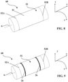
- the tire 10 is substantially of revolution around an axis substantially parallel to the axial direction X.
- the tire 10 is here intended for a passenger vehicle and has sizes 245/45R18.
- the tire 10 comprises a crown 12 comprising a tread 20 intended to come into contact with the ground during rolling and a crown reinforcement 14 extending into the crown 12 in the circumferential direction Z.
- the tire 10 also comprises a layer sealing 15 to an inflation gas being intended to delimit an internal cavity closed with a tire mounting support 10 once the tire 10 is mounted on the mounting support, for example a rim.
- the sealing layer 15 comprises an elastomeric composition comprising an elastomeric matrix comprising at least 50 phr of one or more butyl elastomers.
- the crown reinforcement 14 comprises a working reinforcement 16 comprising a working layer 18 and a hooping reinforcement 17 comprising a single hooping layer 19.
- the working reinforcement 16 comprises a single working layer 18 and is, in this case, consisting of the single working layer 18.
- the hooping reinforcement 17 consists of the hooping layer 19.
- the crown reinforcement 14 is surmounted radially by the tread 20.
- the hooping reinforcement 17, here the hooping layer 19, is arranged radially outside the working reinforcement 16 and is therefore radially interposed between the working reinforcement 16 and the tread 20.
- the hooping reinforcement 17 has an axial width smaller than the axial width of the working layer 18.
- the hooping reinforcement 17 is axially the less wide of the working layer 18 and of the hooping reinforcement 17.
- the tire 10 comprises two sidewalls 22 extending the crown 12 radially inwards.
- the tire 10 further comprises two beads 24 radially inside the sidewalls 22.
- Each sidewall 22 connects each bead 24 to the crown 12.
- Each bead 24 comprises at least one circumferential reinforcing element 26, in this case a rod 28 radially surmounted by a mass of rubber 30 for filling.
- the tire 10 comprises a carcass reinforcement 32 anchored in each bead 24.
- the carcass reinforcement 32 extends in each sidewall 22 and radially internally to the crown 12.
- the crown reinforcement 14 is arranged radially between the tread 20 and the carcass reinforcement 32.
- the carcass reinforcement 32 comprises a carcass layer 34.
- the carcass reinforcement 32 comprises a single carcass layer 34, and in this case consists of the single carcass layer 34.
- the carcass layer 34 comprises a portion 34T of the carcass layer 34 wrapped around each circumferential reinforcement element 26 so as to form in each bead 24 an axially inner portion 38 and an axially outer portion 40.
- the rubber mass 30 of stuffing is interposed between the portions 38, 40 axially inner and outer.
- Other modes of anchoring the carcass layer 34 are possible, for example as described in US5702548 .
- Each working 18, hooping 19 and carcass 34 layer comprises an elastomeric matrix in which are embedded one or more wire reinforcing elements of the corresponding layer.
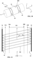
- the hooping reinforcement 17, here the hooping layer 19, is delimited axially by two axial edges 17A, 17B of the hooping reinforcement 17.
- the hooping reinforcement 17 comprises several hooping wire reinforcement elements 170 wound circumferentially helically so as to extend axially from the axial edge 17A to the other axial edge 17B of the hooping reinforcement 17 along a main direction D1 of each hooping wire reinforcement element 170.
- the main direction D1 forms, with the circumferential direction Z of the tire 10, an angle AF, in absolute value, less than or equal to 10°, preferably less than or equal to 7° and more preferably less than or equal to 5°.
- AF -5°.
- the hooping reinforcement has an average axial density of 69 threads per decimeter, ie 0.69 threads per mm.
- the working layer 18 is delimited axially by two axial edges 18A, 18B of the working layer 18.
- the working layer 18 comprises working wire reinforcement elements 180 extending axially from the axial edge 18A to the other axial edge 18B of working layer 18 substantially parallel to each other.
- Each wired working reinforcement element 180 extends along a main direction D2 of each wired working reinforcement element 180.
- the direction D2 forms, with the circumferential direction Z of the tire 10, an angle AT, in absolute value, strictly greater at 10°, preferably ranging from 15° to 50° and more preferably ranging from 18° to 30°.
- AT 24°.
- the carcass layer 34 is delimited axially by two axial edges 34A, 34B of the carcass layer 34.
- the carcass layer 34 comprises carcass wire reinforcement elements 340 extending axially from the axial edge 34A to the other axial edge. 34B of the carcass layer 34.
- Each wired carcass reinforcement element 340 extends in a direction main D3 of each carcass wire reinforcement element 340 forming, with the circumferential direction Z of the tire 10, an angle ACS, in absolute value, strictly less than 80° in a portion 34S of the carcass layer 34 extending axially at the radial plumb of the working layer 18.
- the main direction D3 of each carcass wire reinforcement element 340 forms, with the circumferential direction Z of the tire 10, an angle ACS, in absolute value, greater than or equal to 10°, preferably ranging from 20° to 75° and more preferably ranging from 35° to 70°.
- ACS 43°.
- the portion 34S of the carcass layer 34 extending axially plumb with the working layer 18 has an axial width equal to at least 40%, preferably at least 50% of the axial width L of the working layer 18 and equal to at most 90%, preferably at most 80% of the axial width L of the working layer 18 and in this case equal to 60% of the working layer 18.
- the median plane M of the tire 10 intersects this portion 34S. More preferably, this portion 34S is centered axially on the median plane M of the tire 10.
- each carcass wire reinforcement element 340 forms, with the circumferential direction Z of the tire 10, an angle ACF, in absolute value, ranging from 80° to 90° in at least a portion 34F of the layer of carcass 34 extending radially in each sidewall 22.
- ACF 90°.
- Each portion 34F of the carcass layer 34 extending radially in each sidewall 22 has a radial height equal to at least 5%, preferably at least 15% and more preferably at least 30% of the radial height H of the tire 10 and equal to at most 80%, preferably at most 70% and more preferably at most 60% of the radial height H of the tire 10 and in this case equal to 41% of the radial height H of the tire 10.
- the equatorial circumferential plane E of tire 10 intersects each portion 34F of carcass layer 34 located in each sidewall 22.
- each carcass wire reinforcement element 340 forms, with the circumferential direction Z of the tire 10, an angle ACT, in absolute value, strictly greater than 0°, preferably ranging from 27° to 150° and more preferably ranging from 56° to 123°, in the wound portion 34T of the carcass layer 34.
- the main direction D1 of each hooping wire reinforcement element 170, the main direction D2 of each working wire reinforcement element 180 and the main direction D3 of each carcass wire reinforcement element 340 form, with the circumferential direction Z of the tire 10, in a portion PS' of the tire 10 comprised axially between the axial edges 17A, 17B of the hooping reinforcement 17, angles two by two different in absolute value.
- each portion PS, PS' of the tire 10 has an axial width equal to at least 40%, preferably at least 50% of the axial width L of the working layer 18 and equal to at most 90 %, preferably at most 80% of the axial width L of the working layer 18 and in this case equal to 60% of the axial width L of the working layer 18.
- the median plane M of the tire 10 intersects each portion PS, PS' of the tire 10. More preferably, each portion PS, PS' of the tire 10 is centered axially on the median plane M of the tire 10.
- Each working wire reinforcement element 180 is an assembly of two steel monofilaments each having a diameter equal to 0.30 mm, the two steel monofilaments being wound one with the other at a pitch of 14 mm.
- Each carcass wire reinforcement element 340 conventionally comprises two multifilament strands, each multifilament strand consisting of a yarn of polyester monofilaments, here of PET, these two multifilament strands being individually overtwisted at 240 turns per meter in one direction then twisted together at 240 revolutions per meter in the opposite direction. These two multifilament strands are helically wound around each other. Each of these multifilament strands has a titer equal to 220 tex.
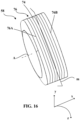
- each hooping wire reinforcement element 170 consists of three multifilament strands 1701, 1702, 1703, and in this case, consists of two multifilament strands 1701, 1702 of aromatic polyamide or aromatic copolyamide and one multifilament strand 1703 of polyamide aliphatic or polyester, and here consisting of two multifilament strands 1701, 1702 of aromatic polyamide, for example Kevlar from Dupont Maydown and a multifilament strand 1703 of aliphatic polyamide, for example Nylon T728 from Kordsa.
- Each multifilament strand 1701, 1702, 1703 is wound helically around a main axis W common to the three multifilament strands.
- each multifilament strand of aromatic polyamide 1701, 1702 ranges from 150 tex to 350 tex and in this case is equal to 330 tex.
- the titer of the multifilament strand of aliphatic polyamide 1703 ranges from 120 tex to 250 tex and in this case is equal to 188 tex.
- the ratio of the total titer, expressed in tex, of aromatic polyamide to the total titer, expressed in tex, of each hooping wire reinforcement element 170 ranges from 0.60 to 0.90, preferably from 0.65 to 0.80 and is here equal to 0.78.
- Each hooping wire reinforcement element 170 is balanced in torsion and is obtained by a process comprising a first step of twisting each multifilament strand 1701, 1702, 1703 according to a number of turns per meter N1 in a first direction of twist.
- the torsion coefficient K of each hooping wire reinforcement element 170 described above ranges from 140 to 260, preferably from 180 to 220 and even more preferably from 205 to 220 and here equal to 212 with an average density of the material constituting each wire reinforcing element for hooping 170 equal to 1.37 by taking an aromatic polyamide density equal to 1.44 and an aliphatic polyamide density equal to 1.14.
- the hooping reinforcement 17 also has a tangent modulus M13% at 1.3% elongation ranging from 200 to 650 daN/mm.
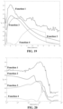
- the tangent modulus M13% is determined from the tangent modulus M13'% at 1.3% elongation of each hooping wire reinforcement element 170, illustrated in the figure 6 which has been multiplied by the average axial density of hooping wire reinforcement elements 170 per mm of hooping reinforcement, and here by the average number of turns of the hooping wire reinforcement elements per mm of hooping reinforcement 17.
- the tangent modulus M13% is greater than or equal to 220 daN/mm and less than or equal to 600 daN/mm, preferably less than or equal to 500 daN/mm and here equal to 322 daN/mm.
- the hooping reinforcement 14 develops, under a force equal to 2 daN/mm, a tangent modulus M2D ranging from 150 to 400 daN/mm. More specifically, the hooping reinforcement 14 develops, under a force equal to 2 daN/mm, a tangent modulus M2D greater than or equal to 200 daN/mm and less than or equal to 350 daN/mm.
- the force equal to 2 daN/mm represents a force equivalent to 2.9 daN/element of hooping wire reinforcement, which, on the figure 6 gives an equivalent tangent modulus M2'D equal to 4.35 daN/%, i.e. an M2D modulus equal to 300 daN/mm for the hooping reinforcement 14.
- the tire 10 is obtained by a process according to the invention which will be described with reference to the figures 7 to 13 .
- a wound working assembly 50 and a wound carcass assembly 52 are manufactured by arranging the wire reinforcement elements 180 and 340 of each assembly 50 and 52 parallel to each other and by embedding them, for example by calendering , in a non-crosslinked composition comprising at least one elastomer, the composition being intended to form an elastomeric matrix once crosslinked.
- a so-called straight ply is obtained, in which the wire reinforcing elements are parallel to each other and are parallel to the main direction of the ply.
- portions of each straight ply are cut at a cutting angle and these portions are butted together so as to obtain a so-called angled ply, in which the wired reinforcing elements of the ply are parallel to each other. and form an angle with the main direction of the web equal to the cutting angle.
- a single working ply 49 and a single carcass ply 51 are obtained, the axial width of each of which, that is to say the dimension in a direction perpendicular to the longitudinal edges of each ply is equal to the axial width respectively of each set of wound work 50 and carcass 52 which will be formed subsequently.
- a sealing ply 70 is formed by winding around a support 60 having a substantially cylindrical shape around its main axis A, a wound sealing assembly 72 intended to form the sealing layer 15.
- the support 60 has a substantially cylindrical bearing surface with a radius equal to 235 mm.
- each wired carcass reinforcement element 340 extends, in the carcass ply 51, along a main direction K3 of each wired carcass reinforcement element 340 in the carcass ply 51.
- the main direction K3 forms, with the circumferential direction z of the support 60, an initial angle A3 of each carcass wire reinforcement element 340, in absolute value, strictly greater than 0°, preferably ranging from 27° to 150° and more preferably ranging from 56° to 123°.
- A3 75°.
- the two circumferential reinforcing elements 26 are arranged around the wound carcass assembly 52 and axially returned towards the inside each axial edge 52A, 52B of the wound carcass assembly 52 so as to radially cover each circumferential reinforcement element 26 by each axial edge 52A, 52B of the wound carcass assembly 52 and to form a portion 59 of the wound carcass assembly 52 wound around each circumferential reinforcement element 26.
- the portion 59 of the wound carcass assembly 52 is intended to form the portion 34T of the carcass layer 34 wound around each circumferential reinforcement element 26 in the tire.
- FIG 11 a diagram illustrating the arrangement of the carcass wire reinforcement elements 340 at the end of the step of axial reversal of the axial edges 52A, 52B of the wound carcass assembly 52 around the circumferential reinforcement elements 26.
- the initial angle A3 described above has been shown as well as each portion 59.
- the wound working assembly 50 is delimited axially by two axial edges 50A, 50B of the wound working assembly 50 and comprises the wired working reinforcement elements 180 extending substantially parallel to each other axially from the axial edge 50A to the other axial edge 50B of the 'wound working assembly 50.
- Each wired working reinforcement element 180 extends, in the working ply 49, along a main direction K2 of each wired working reinforcement element 180 in the working ply 49.
- the main direction K2 forms, with the circumferential direction z of the support 60, an initial angle A2 of each wired working reinforcement element 180, in absolute value, strictly greater than 0°, preferably ranging from 4° to 60° and more preferably ranging from 16° to 47°.
- A2 35°.
- the wound carcass assembly 52 and the wound working assembly 50 then form an assembly 58 of substantially cylindrical shape around the main axis A of the support 60.
- FIG 13 a diagram similar to that of figure 11 illustrating the arrangement of the carcass wire reinforcement elements 340 and the work wire reinforcement elements 180 at the end of the step of forming the wound working assembly 50.
- the initial angles A2 and A3 have been represented.
- each working wire reinforcement element 180 and the main direction K3 of each carcass wire reinforcement element 340 form, with the circumferential direction z of the support 60, in a portion AC of the assembly 58 comprised axially between the axial edges 50A, 50B of the rolled-up work assembly 50, initial angles A2 and A3 of opposite orientations.
- the assembly 58 of substantially cylindrical shape is deformed around the main axis A of the support 60 so as to obtain the assembly 58 of substantially toroidal shape around the main axis A of the support 60.
- the assembly is obtained distorted 58 shown on the figure 14 .
- the bearing surface of the support 60 then has, at the median plane of the support, a radius equal to 327 mm.
- the assembly 58 of substantially cylindrical shape is deformed around the main axis A of the support 60 so as to obtain an assembly 58 of substantially toroidal shape around the main axis A of the support 60 so that the main direction K3 of each wired carcass reinforcement element 340 forms, with the circumferential direction z of the support 60, a final angle B3S of each wired carcass reinforcement element 340, in absolute value, strictly less than 80°, in a portion 52S of the wound carcass assembly 52 extending axially radially plumb with the wound working assembly 50.
- the final angle B3S is, in absolute value, greater than or equal to 10°, preferably ranges from 20° to 75° and more preferably ranges from 35 to 70°.
- B3S 43°.
- the portion 52S of the wound carcass assembly 52 is intended to form the portion 34S of the carcass layer 34.
- the portion 52S of the wound carcass assembly 52 extending axially radially plumb with the wound working assembly 50 has an axial width equal to at least 40%, preferably at least 50% of the axial width I of the rolled-up working set 50 and equal to at most 90%, preferably at most 80% of the axial width I of the rolled-up working set 50 and, in this case is equal to 60% of the axial width I of the coiled working assembly 50.
- the median plane m of the assembly 58 intersects this portion 52S. More preferably, this portion 52S is centered axially on the median plane m of the assembly 58.
- the assembly 58 of substantially cylindrical shape is deformed around the main axis A of the support 60 so as to obtain the assembly 58 of substantially toroidal shape around the main axis A of the support 60 also so that, the main direction K3 of each carcass wire reinforcement element 340 forms, with the circumferential direction z of the support 60, a final angle B3F of each carcass wire reinforcement element 340 ranging, in absolute value, from 80° to 90°, in a portion 52F of the rolled carcass assembly 52 intended to extend radially in each sidewall 22 of the tire 10.
- Each portion 52F of the rolled carcass assembly 52 is intended to form each portion 34F of the carcass layer 34.
- Each portion 52F of the wound carcass assembly 52 intended to extend radially in each sidewall 22 has a radial height equal to at least 5%, preferably at least 15% and even more preferably at least 30% of the radial height H of the manufactured tire and equal to at most 80%, preferably at most 70% and even more preferably at most 60% of the radial height H of the manufactured tire, and in this case is equal to 41% of the radial height H tire manufactured.
- the equatorial circumferential plane e of the assembly 58 intersects each portion 52F of the wound carcass assembly 52 intended to be located in each sidewall 22.
- the final angle B3T formed by the main direction K3 of each carcass wire reinforcement element 340, with the circumferential direction z of the support 60, in the wound portion 59 of the wound carcass assembly 52, is substantially identical to the initial angle A3 before the deformation step.
- the assembly 58 of substantially cylindrical shape is deformed around the main axis A of the support 60 so as to obtain the assembly 58 of substantially toroidal shape around the main axis A of the support 60 also so that, the main direction K2 of each wired working reinforcement element 180 form, with the circumferential direction z of the support 60, a final angle B2 of each wired working reinforcement element 180, in absolute value, strictly greater than 10°.
- each working wire reinforcement element 180 and the main direction K3 of each carcass wire reinforcement element 340 form, with the circumferential direction z of the support 60, in the portion AC of the assembly 58 comprised axially between the axial edges 50A, 50B of the coiled work assembly 50, end angles B2 and B3S of opposite orientations.
- wire reinforcing hooping elements 170 are embedded in an elastomeric matrix to form a hooping ply 74.
- a wound hooping assembly 76 intended to form the hooping reinforcement 17.
- the wound hooping assembly 76 is formed by helical winding of the hooping sheet 74 on a toroidal form then the wound hooping assembly 76 is transferred with the aid of a transfer ring radially to the outside of the assembly 58 formed beforehand.
- the hooping sheet 74 can be directly wound circumferentially helically around the assembly 58 formed beforehand so as to form the wound hooping assembly 76.
- the wound hooping assembly 76 develops, under a force equal to 2 daN/mm, a M2D tangent modulus ranging from 155 to 420 daN/mm. More precisely, the hooping assembly 76 develops, under a force equal to 2 daN/mm, a tangent modulus M2Dc greater than or equal to 210 daN/mm and less than or equal to 368 daN/mm
- the density average axial strength of hooping wire reinforcement elements 170 in the wound hooping assembly 76 is slightly lower than that of the hooping reinforcement 17, in this case equal to 0.66 elements per mm
- the force equal to 2 daN/mm represents a force equivalent to 3.03 daN/binding wire reinforcement element, which corresponds to an equivalent tangent modulus M2'Dc equal to 4.57 daN/%, i.e. a modulus M2Dc equal to 301 daN/mm for the coiled shrink assembly 76.
- the coiled hooping assembly 76 has an axial width that is smaller than the axial width of the coiled working assembly 50.
- the coiled hooping assembly 76 is axially the least wide of the coiled work 50 and coiled hooping 76.
- the angle A1 formed by the main direction K1 of each hooping wire reinforcement element 170 with the circumferential direction z of the support 60 is, in absolute value, less than or equal to 10°, preferably less than or equal to 7° and more preferably less than or equal to 5° and here equal to 5°.
- the main direction K1 of each hooping wire reinforcement element 170, the main direction K2 of each working wire reinforcement element 180 and the main direction D3 of each carcass wire reinforcement element 340 form, with the circumferential direction z of the support 60, in a portion AC' of the assembly 58 and of the wound hooping assembly 76 comprised axially between the axial edges 76A, 76B of the wound hooping assembly 76, angles two by two different in absolute value.
- the portion AC' of the assembly 58 and of the wound hooping assembly axially between the axial edges 76A, 76B of the wound hooping assembly 76 has an axial width equal to at least 40%, preferably at least 50 % of the axial width L of the rolled up working set 50 and at most 90%, preferably at most 80% of the axial width L of the rolled up working set 50 and in this case here 60% of the width axis L of the rolled-up work assembly 50.
- the median plane m of the assembly 58 intersects this portion AC′. More preferably, this portion AC' is centered axially on the median plane m of the assembly 58.
- a strip of polymeric material intended to form the tread 20 is arranged, so as to form a raw blank of the tire 10.
- the strip of polymeric material intended to form the tread 20 then transfer this assembly radially to the outside of the assembly 58 previously formed on the support 60.
- the green blank of the tire 10 formed from the previously formed assembly 58 and the wound hooping assembly 76 is molded, by radially and circumferentially expanding the green blank so as to flatten a radially outer surface of the blank against a molding wall of a cross-linking mold.
- the green blank is crosslinked in the crosslinking mold so as to obtain the tire 10, for example by vulcanization.
- the most relevant descriptor was first determined for evaluating the rolling resistance of tires comprising a single working layer. For this, the correlation between the correlation between the tangent modulus of the hooping reinforcement and the rolling resistance simulated on tires comprising a single working layer similar to the tire 10 described above and comprising various wire-based hooping reinforcing elements.
- rolling resistance simulations were carried out for hooping wire reinforcing elements having different values of tangent modulus. Then, we scanned the different forces at which we can calculate this tangent modulus. Then, an attempt was made to pass each correlation function in the cloud of simulated rolling resistance points and the correlation coefficient R2 was noted for each of the correlation functions at each effort level.
- Table 1 below shows the tangent moduli M13% at 1.3% of nine hooping wire reinforcement elements as well as the corresponding rolling resistance RR13 of a tire comprising a single working layer similar to those simulated. .
- Table 1 below also summarizes the tangent moduli M1% at 1% elongation simulated for hooping assemblies comprising the same nine hooping wire reinforcement elements as well as the corresponding rolling resistance R1 of a tire comprising two working layers analogous to those simulated.
- Element 1 is the hooping wire reinforcement element 170 described above.
- Element 2 consists of two multifilament strands of aromatic polyamide of 250 tex each and one multifilament strand of aliphatic polyamide of 140 tex individually wound then together in a helix according to a twist equal to 300 turns per meter.
- Element 3 consists of two multifilament strands of aromatic polyamide of 250 tex each and one multifilament strand of aliphatic polyamide of 210 tex wound individually and then together in a helix according to a twist equal to 300 turns per meter.
- Element 4 consists of two multifilament strands of aromatic polyamide of 250 tex each and one multifilament strand of polyethylene terephthalate of 220 tex wound individually then together in a helix according to a twist equal to 300 turns per meter.
- the element 5 consists of two multifilament strands of aromatic polyamide of 167 tex each and one multifilament strand of aliphatic polyamide of 140 tex wound individually then together in a helix according to a twist equal to 360 turns per meter.
- the element 6 consists of three multifilament strands of polyethylene terephthalate of 440 tex each, individually wound then together in a helix according to a twist equal to 160 turns per meter.
- Elements 7 and 8 have a "Core Insertion" type structure such that described in WO2019/122621 .
- Element 7 comprises a core strand of aliphatic polyamide of 47 tex individually wound at 340 turns per meter and three layer strands of aromatic polyamide of 167 tex each individually wound at 315 turns per meter, the core and layer being wound together at 315 turns per meter.
- the element 8 comprises a core strand of aliphatic polyamide of 47 tex individually wound at 300 turns per meter and three layer strands of aromatic polyamide of 167 tex each individually wound at 270 turns per meter, the core and layer being wound together at 270 turns per meter.
- Element 9 has an A110/1/2/3 triple twist structure as described in WO2019/180367 .
- Table 1 M13% (daN/mm) RR13 (kg/t) M1% (daN/mm) RR1 (kg/t) Element 1 322 5.31 314 5.91 Element 2 349 5.31 332 5.92 Element 3 226 5.34 218 5.89 Element 4 434 5.32 398 5.95 Element 5 222 5.33 218 5.89 Element 6 297 5.32 291 5.91 Element 7 40 5.43 36 5.95 Element 8 112 5.39 101 5.93 Element 9 935 5.39 887 6.10
- elements 1 to 6 do not make it possible to obtain a significantly improved rolling resistance (by significantly improved, we mean here less by at least 0.05 kg.t ) compared to elements 7 to 9, and particularly compared to elements 7 and 8.
- these elements 1 to 6 make it possible to obtain a significantly improved rolling resistance (lower by at least 0. 05 kg.t) with respect to elements 7 to 9 in a tire comprising a single working layer.
- the elements 1 to 6 present a risk of not reaching the expected volume, in particular with respect to the element 8.
- these elements 1 to 6 make it possible to achieve the expected volume without running the risk of not containing it, unlike element 9 which would not make it possible to obtain the expected volume for a tire comprising a single working layer.
- element 9 which would not make it possible to obtain the expected volume for a tire comprising a single working layer.
- the invention may in particular be implemented by using two carcass layers instead of a single carcass layer.
- the or each wired hooping reinforcing element consists of three multifilament polyester strands.
- the title of each polyester multifilament strand ranges from 300 tex to 500 tex, for example is equal to 440 tex and the assembly twist of the three polyester multifilament strands around the common main axis ranges from 100 turns per meter to 250 turns per meter, for example is equal to 160 turns per meter.
- the torsion coefficient K of the or each hooping wire reinforcement element of this variant ranges from 120 to 260, preferably from 130 to 200 and even more preferably from 130 to 160, for example is equal to 156.
Landscapes
- Engineering & Computer Science (AREA)
- Mechanical Engineering (AREA)
- Tires In General (AREA)
- Yarns And Mechanical Finishing Of Yarns Or Ropes (AREA)
Applications Claiming Priority (2)
| Application Number | Priority Date | Filing Date | Title |
|---|---|---|---|
| FR1911527A FR3102095A1 (fr) | 2019-10-16 | 2019-10-16 | Pneumatique a faible resistance au roulement et son procede de fabrication |
| PCT/FR2020/051793 WO2021074511A1 (fr) | 2019-10-16 | 2020-10-09 | Pneumatique a faible resistance au roulement et son procede de fabrication |
Publications (2)
| Publication Number | Publication Date |
|---|---|
| EP4045337A1 EP4045337A1 (fr) | 2022-08-24 |
| EP4045337B1 true EP4045337B1 (fr) | 2023-06-07 |
Family
ID=69468759
Family Applications (1)
| Application Number | Title | Priority Date | Filing Date |
|---|---|---|---|
| EP20797827.1A Active EP4045337B1 (fr) | 2019-10-16 | 2020-10-09 | Pneumatique a faible resistance au roulement et son procede de fabrication |
Country Status (6)
| Country | Link |
|---|---|
| US (1) | US20230137115A1 (enExample) |
| EP (1) | EP4045337B1 (enExample) |
| JP (1) | JP7657788B2 (enExample) |
| CN (1) | CN114761253B (enExample) |
| FR (1) | FR3102095A1 (enExample) |
| WO (1) | WO2021074511A1 (enExample) |
Families Citing this family (7)
| Publication number | Priority date | Publication date | Assignee | Title |
|---|---|---|---|---|
| EP4178811B1 (fr) * | 2020-07-08 | 2024-11-06 | Compagnie Generale Des Etablissements Michelin | Procede de fabrication simplifie d'un pneumatique a une seule couche de travail |
| FR3125461B1 (fr) * | 2021-07-26 | 2023-07-14 | Michelin & Cie | Pneumatique pour motocylcette a haute vitesse limite |
| DE102023200333A1 (de) * | 2023-01-17 | 2024-07-18 | Continental Reifen Deutschland Gmbh | Fahrzeugreifen |
| FR3163896A1 (fr) | 2024-06-27 | 2026-01-02 | Compagnie Generale Des Etablissements Michelin | Pneumatique présentant un agencement d’armature de frettage optimisé |
| FR3165689A1 (fr) | 2024-08-26 | 2026-02-27 | Compagnie Generale Des Etablissements Michelin | Pneumatique à performances durables améliorées |
| FR3165690A1 (fr) | 2024-08-26 | 2026-02-27 | Compagnie Generale Des Etablissements Michelin | Pneumatique à performances durables maximisées |
| FR3153564A1 (fr) | 2024-12-12 | 2025-04-04 | Compagnie Generale Des Etablissements Michelin | Pneumatique |
Family Cites Families (26)
| Publication number | Priority date | Publication date | Assignee | Title |
|---|---|---|---|---|
| NL131398C (enExample) | 1964-05-14 | Michelin & Cie | ||
| FR2736006A1 (fr) | 1995-06-29 | 1997-01-03 | Sedepro | Pneumatique comportant des cables circonferentiels pour ancrer la carcasse, procede de preparation de tels cables |
| FR2797213B1 (fr) | 1999-08-02 | 2002-08-30 | Michelin Soc Tech | Procede de fabrication d'un pneumatique avec preconformation d'une nappe de carcasse radiale pour rendre obliques les cables de la partie centrale |
| BR0210150B1 (pt) * | 2002-04-08 | 2011-04-19 | pneumático. | |
| JP2004130835A (ja) * | 2002-10-08 | 2004-04-30 | Bridgestone Corp | ラジアルタイヤ |
| JP2006137315A (ja) * | 2004-11-12 | 2006-06-01 | Bridgestone Corp | 空気入りラジアルタイヤ及びその製造方法 |
| JP2009227229A (ja) * | 2008-03-25 | 2009-10-08 | Toyo Tire & Rubber Co Ltd | 空気入りラジアルタイヤ |
| FR2939722B1 (fr) * | 2008-12-17 | 2010-12-31 | Michelin Soc Tech | Pneumatique pour vehicules lourds dont l'armature de sommet comporte au moins une couche d'elements de renforcement circonferentiels |
| FR2974583B1 (fr) * | 2011-04-28 | 2013-06-14 | Michelin Soc Tech | Cable textile composite aramide-polycetone |
| KR101260390B1 (ko) * | 2011-07-25 | 2013-05-21 | 한국타이어 주식회사 | 아라미드 코드와 나일론 66과의 하이브리드 코드 및 이를 보강 코드로 사용하는 공기입 타이어 |
| FR2978769B1 (fr) | 2011-08-04 | 2013-09-27 | Michelin Soc Tech | Composition adhesive aqueuse a base de polyaldehyde et de polyphenol |
| JP5261584B2 (ja) * | 2012-01-20 | 2013-08-14 | 住友ゴム工業株式会社 | 空気入りタイヤの製造方法 |
| FR3008996B1 (fr) | 2013-07-29 | 2016-01-01 | Michelin & Cie | Produit renforce a faible epaisseur et pneumatique comprenant ce produit |
| CN105517814B (zh) * | 2013-08-08 | 2018-01-30 | 倍耐力轮胎股份公司 | 提高用于车辆车轮的轮胎的性能的方法和用于车辆车轮的轮胎 |
| US20170100964A1 (en) * | 2014-04-22 | 2017-04-13 | Sumitomo Rubber Industries, Ltd. | Pneumatic tire, and pneumatic tire production method |
| JP6093325B2 (ja) * | 2014-04-22 | 2017-03-08 | 住友ゴム工業株式会社 | 空気入りタイヤの製造方法、及び空気入りタイヤ |
| DE102014216260A1 (de) * | 2014-08-15 | 2016-02-18 | Continental Reifen Deutschland Gmbh | Hybridkord zur Verwendung als Festigkeitsträger in einer Gürtelbandage eines Fahrzeugluftreifens |
| DE102015201738A1 (de) * | 2015-02-02 | 2016-08-18 | Continental Reifen Deutschland Gmbh | Fahrzeugluftreifen |
| FR3035026B1 (fr) * | 2015-04-17 | 2017-03-31 | Michelin & Cie | Armature de renforcement de pneumatique |
| JP6807263B2 (ja) * | 2016-03-30 | 2021-01-06 | 株式会社ブリヂストン | 空気入りタイヤ |
| FR3049610A1 (fr) | 2016-04-01 | 2017-10-06 | Michelin & Cie | Composition adhesive aqueuse comportant une resine thermodurcissable et un latex |
| FR3050401B1 (fr) * | 2016-04-25 | 2018-04-06 | Compagnie Generale Des Etablissements Michelin | Pneu avion ayant une armature de carcasse a endurance amelioree |
| FR3056215A1 (fr) * | 2016-09-19 | 2018-03-23 | Compagnie Generale Des Etablissements Michelin | Composite d’elastomere et pneumatique comprenant ce composite |
| EP3727826B1 (fr) | 2017-12-22 | 2023-07-12 | Compagnie Generale Des Etablissements Michelin | Procédé de fabrication d'un élément filaire de renfort |
| US12246565B2 (en) * | 2017-12-22 | 2025-03-11 | Compagnie Generale Des Etablissements Michelin | Pneumatic tire comprising specified hoop reinforcer element |
| US20210155045A1 (en) | 2018-03-20 | 2021-05-27 | Compagnie Generale Des Etablissements Michelin | Pneumatic tire comprising an improved aramid textile cord with an at least triple twist |
-
2019
- 2019-10-16 FR FR1911527A patent/FR3102095A1/fr not_active Ceased
-
2020
- 2020-10-09 CN CN202080080731.5A patent/CN114761253B/zh active Active
- 2020-10-09 US US17/768,967 patent/US20230137115A1/en active Pending
- 2020-10-09 JP JP2022522345A patent/JP7657788B2/ja active Active
- 2020-10-09 WO PCT/FR2020/051793 patent/WO2021074511A1/fr not_active Ceased
- 2020-10-09 EP EP20797827.1A patent/EP4045337B1/fr active Active
Also Published As
| Publication number | Publication date |
|---|---|
| WO2021074511A1 (fr) | 2021-04-22 |
| CN114761253A (zh) | 2022-07-15 |
| JP7657788B2 (ja) | 2025-04-07 |
| JP2022552527A (ja) | 2022-12-16 |
| FR3102095A1 (fr) | 2021-04-23 |
| EP4045337A1 (fr) | 2022-08-24 |
| US20230137115A1 (en) | 2023-05-04 |
| CN114761253B (zh) | 2023-08-11 |
Similar Documents
| Publication | Publication Date | Title |
|---|---|---|
| EP4045337B1 (fr) | Pneumatique a faible resistance au roulement et son procede de fabrication | |
| EP3827125B1 (fr) | Câble ouvert a haute compressibilite | |
| EP3826863B1 (fr) | Cables metalliques bi-modules | |
| FR3105097A1 (fr) | Pneumatique comprenant un bourrelet perfectionné | |
| WO2022074342A1 (fr) | Pneumatique comprenant une unique couche de carcasse | |
| EP4004275B1 (fr) | Cable ouvert renforcant a haute compressibilite | |
| WO2019180367A1 (fr) | Pneumatique comprenant un câblé textile aramide perfectionne à au moins triple torsion | |
| WO2019180369A1 (fr) | Câblé textile aramide perfectionne à au moins triple torsion | |
| EP4096938B1 (fr) | Pneumatique pour motocylcette | |
| EP4045336B1 (fr) | Pneumatique a emission de bruit reduit et son procede de fabrication | |
| EP4045299B1 (fr) | Pneumatique presentant une uniformite amelioree et son procede de fabrication | |
| EP4178811B1 (fr) | Procede de fabrication simplifie d'un pneumatique a une seule couche de travail | |
| EP4100264B1 (fr) | Pneumatique pour véhicule agricole comprenant un élément de renfort de carcasse hybride | |
| EP4100265B1 (fr) | Pneumatique pour véhicule agricole comprenant une armature de carcasse monocouche | |
| EP3880492B1 (fr) | Pneumatique pour véhicule à deux roues comprenant un renfort de frettage hybride | |
| WO2024017580A1 (fr) | Tissu pour pneumatique comprenant des éléments de renfort comprenant un assemblage constitué de deux brins multifilamentaires de polyamide 5,6 | |
| WO2023007071A1 (fr) | Pneumatique pour motocylcette a haute vitesse limite | |
| EP4288296A1 (fr) | Procede de fabrication d'un pneumatique presentant un chemin conducteur |
Legal Events
| Date | Code | Title | Description |
|---|---|---|---|
| STAA | Information on the status of an ep patent application or granted ep patent |
Free format text: STATUS: UNKNOWN |
|
| STAA | Information on the status of an ep patent application or granted ep patent |
Free format text: STATUS: THE INTERNATIONAL PUBLICATION HAS BEEN MADE |
|
| PUAI | Public reference made under article 153(3) epc to a published international application that has entered the european phase |
Free format text: ORIGINAL CODE: 0009012 |
|
| STAA | Information on the status of an ep patent application or granted ep patent |
Free format text: STATUS: REQUEST FOR EXAMINATION WAS MADE |
|
| 17P | Request for examination filed |
Effective date: 20220516 |
|
| AK | Designated contracting states |
Kind code of ref document: A1 Designated state(s): AL AT BE BG CH CY CZ DE DK EE ES FI FR GB GR HR HU IE IS IT LI LT LU LV MC MK MT NL NO PL PT RO RS SE SI SK SM TR |
|
| DAV | Request for validation of the european patent (deleted) | ||
| DAX | Request for extension of the european patent (deleted) | ||
| GRAP | Despatch of communication of intention to grant a patent |
Free format text: ORIGINAL CODE: EPIDOSNIGR1 |
|
| STAA | Information on the status of an ep patent application or granted ep patent |
Free format text: STATUS: GRANT OF PATENT IS INTENDED |
|
| INTG | Intention to grant announced |
Effective date: 20230228 |
|
| GRAS | Grant fee paid |
Free format text: ORIGINAL CODE: EPIDOSNIGR3 |
|
| GRAA | (expected) grant |
Free format text: ORIGINAL CODE: 0009210 |
|
| STAA | Information on the status of an ep patent application or granted ep patent |
Free format text: STATUS: THE PATENT HAS BEEN GRANTED |
|
| AK | Designated contracting states |
Kind code of ref document: B1 Designated state(s): AL AT BE BG CH CY CZ DE DK EE ES FI FR GB GR HR HU IE IS IT LI LT LU LV MC MK MT NL NO PL PT RO RS SE SI SK SM TR |
|
| REG | Reference to a national code |
Ref country code: GB Ref legal event code: FG4D Free format text: NOT ENGLISH |
|
| REG | Reference to a national code |
Ref country code: CH Ref legal event code: EP Ref country code: AT Ref legal event code: REF Ref document number: 1573942 Country of ref document: AT Kind code of ref document: T Effective date: 20230615 Ref country code: DE Ref legal event code: R096 Ref document number: 602020012302 Country of ref document: DE |
|
| REG | Reference to a national code |
Ref country code: LT Ref legal event code: MG9D |
|
| REG | Reference to a national code |
Ref country code: NL Ref legal event code: MP Effective date: 20230607 |
|
| PG25 | Lapsed in a contracting state [announced via postgrant information from national office to epo] |
Ref country code: SE Free format text: LAPSE BECAUSE OF FAILURE TO SUBMIT A TRANSLATION OF THE DESCRIPTION OR TO PAY THE FEE WITHIN THE PRESCRIBED TIME-LIMIT Effective date: 20230607 Ref country code: NO Free format text: LAPSE BECAUSE OF FAILURE TO SUBMIT A TRANSLATION OF THE DESCRIPTION OR TO PAY THE FEE WITHIN THE PRESCRIBED TIME-LIMIT Effective date: 20230907 Ref country code: ES Free format text: LAPSE BECAUSE OF FAILURE TO SUBMIT A TRANSLATION OF THE DESCRIPTION OR TO PAY THE FEE WITHIN THE PRESCRIBED TIME-LIMIT Effective date: 20230607 |
|
| REG | Reference to a national code |
Ref country code: AT Ref legal event code: MK05 Ref document number: 1573942 Country of ref document: AT Kind code of ref document: T Effective date: 20230607 |
|
| PG25 | Lapsed in a contracting state [announced via postgrant information from national office to epo] |
Ref country code: RS Free format text: LAPSE BECAUSE OF FAILURE TO SUBMIT A TRANSLATION OF THE DESCRIPTION OR TO PAY THE FEE WITHIN THE PRESCRIBED TIME-LIMIT Effective date: 20230607 Ref country code: NL Free format text: LAPSE BECAUSE OF FAILURE TO SUBMIT A TRANSLATION OF THE DESCRIPTION OR TO PAY THE FEE WITHIN THE PRESCRIBED TIME-LIMIT Effective date: 20230607 Ref country code: LV Free format text: LAPSE BECAUSE OF FAILURE TO SUBMIT A TRANSLATION OF THE DESCRIPTION OR TO PAY THE FEE WITHIN THE PRESCRIBED TIME-LIMIT Effective date: 20230607 Ref country code: LT Free format text: LAPSE BECAUSE OF FAILURE TO SUBMIT A TRANSLATION OF THE DESCRIPTION OR TO PAY THE FEE WITHIN THE PRESCRIBED TIME-LIMIT Effective date: 20230607 Ref country code: HR Free format text: LAPSE BECAUSE OF FAILURE TO SUBMIT A TRANSLATION OF THE DESCRIPTION OR TO PAY THE FEE WITHIN THE PRESCRIBED TIME-LIMIT Effective date: 20230607 Ref country code: GR Free format text: LAPSE BECAUSE OF FAILURE TO SUBMIT A TRANSLATION OF THE DESCRIPTION OR TO PAY THE FEE WITHIN THE PRESCRIBED TIME-LIMIT Effective date: 20230908 |
|
| PG25 | Lapsed in a contracting state [announced via postgrant information from national office to epo] |
Ref country code: FI Free format text: LAPSE BECAUSE OF FAILURE TO SUBMIT A TRANSLATION OF THE DESCRIPTION OR TO PAY THE FEE WITHIN THE PRESCRIBED TIME-LIMIT Effective date: 20230607 |
|
| PG25 | Lapsed in a contracting state [announced via postgrant information from national office to epo] |
Ref country code: SK Free format text: LAPSE BECAUSE OF FAILURE TO SUBMIT A TRANSLATION OF THE DESCRIPTION OR TO PAY THE FEE WITHIN THE PRESCRIBED TIME-LIMIT Effective date: 20230607 |
|
| PG25 | Lapsed in a contracting state [announced via postgrant information from national office to epo] |
Ref country code: IS Free format text: LAPSE BECAUSE OF FAILURE TO SUBMIT A TRANSLATION OF THE DESCRIPTION OR TO PAY THE FEE WITHIN THE PRESCRIBED TIME-LIMIT Effective date: 20231007 |
|
| PG25 | Lapsed in a contracting state [announced via postgrant information from national office to epo] |
Ref country code: SM Free format text: LAPSE BECAUSE OF FAILURE TO SUBMIT A TRANSLATION OF THE DESCRIPTION OR TO PAY THE FEE WITHIN THE PRESCRIBED TIME-LIMIT Effective date: 20230607 Ref country code: SK Free format text: LAPSE BECAUSE OF FAILURE TO SUBMIT A TRANSLATION OF THE DESCRIPTION OR TO PAY THE FEE WITHIN THE PRESCRIBED TIME-LIMIT Effective date: 20230607 Ref country code: RO Free format text: LAPSE BECAUSE OF FAILURE TO SUBMIT A TRANSLATION OF THE DESCRIPTION OR TO PAY THE FEE WITHIN THE PRESCRIBED TIME-LIMIT Effective date: 20230607 Ref country code: PT Free format text: LAPSE BECAUSE OF FAILURE TO SUBMIT A TRANSLATION OF THE DESCRIPTION OR TO PAY THE FEE WITHIN THE PRESCRIBED TIME-LIMIT Effective date: 20231009 Ref country code: IS Free format text: LAPSE BECAUSE OF FAILURE TO SUBMIT A TRANSLATION OF THE DESCRIPTION OR TO PAY THE FEE WITHIN THE PRESCRIBED TIME-LIMIT Effective date: 20231007 Ref country code: EE Free format text: LAPSE BECAUSE OF FAILURE TO SUBMIT A TRANSLATION OF THE DESCRIPTION OR TO PAY THE FEE WITHIN THE PRESCRIBED TIME-LIMIT Effective date: 20230607 Ref country code: CZ Free format text: LAPSE BECAUSE OF FAILURE TO SUBMIT A TRANSLATION OF THE DESCRIPTION OR TO PAY THE FEE WITHIN THE PRESCRIBED TIME-LIMIT Effective date: 20230607 Ref country code: AT Free format text: LAPSE BECAUSE OF FAILURE TO SUBMIT A TRANSLATION OF THE DESCRIPTION OR TO PAY THE FEE WITHIN THE PRESCRIBED TIME-LIMIT Effective date: 20230607 |
|
| PG25 | Lapsed in a contracting state [announced via postgrant information from national office to epo] |
Ref country code: PL Free format text: LAPSE BECAUSE OF FAILURE TO SUBMIT A TRANSLATION OF THE DESCRIPTION OR TO PAY THE FEE WITHIN THE PRESCRIBED TIME-LIMIT Effective date: 20230607 |
|
| REG | Reference to a national code |
Ref country code: DE Ref legal event code: R097 Ref document number: 602020012302 Country of ref document: DE |
|
| PLBE | No opposition filed within time limit |
Free format text: ORIGINAL CODE: 0009261 |
|
| STAA | Information on the status of an ep patent application or granted ep patent |
Free format text: STATUS: NO OPPOSITION FILED WITHIN TIME LIMIT |
|
| PG25 | Lapsed in a contracting state [announced via postgrant information from national office to epo] |
Ref country code: DK Free format text: LAPSE BECAUSE OF FAILURE TO SUBMIT A TRANSLATION OF THE DESCRIPTION OR TO PAY THE FEE WITHIN THE PRESCRIBED TIME-LIMIT Effective date: 20230607 |
|
| PG25 | Lapsed in a contracting state [announced via postgrant information from national office to epo] |
Ref country code: SI Free format text: LAPSE BECAUSE OF FAILURE TO SUBMIT A TRANSLATION OF THE DESCRIPTION OR TO PAY THE FEE WITHIN THE PRESCRIBED TIME-LIMIT Effective date: 20230607 |
|
| 26N | No opposition filed |
Effective date: 20240308 |
|
| PG25 | Lapsed in a contracting state [announced via postgrant information from national office to epo] |
Ref country code: SI Free format text: LAPSE BECAUSE OF FAILURE TO SUBMIT A TRANSLATION OF THE DESCRIPTION OR TO PAY THE FEE WITHIN THE PRESCRIBED TIME-LIMIT Effective date: 20230607 Ref country code: IT Free format text: LAPSE BECAUSE OF FAILURE TO SUBMIT A TRANSLATION OF THE DESCRIPTION OR TO PAY THE FEE WITHIN THE PRESCRIBED TIME-LIMIT Effective date: 20230607 Ref country code: MC Free format text: LAPSE BECAUSE OF FAILURE TO SUBMIT A TRANSLATION OF THE DESCRIPTION OR TO PAY THE FEE WITHIN THE PRESCRIBED TIME-LIMIT Effective date: 20230607 |
|
| REG | Reference to a national code |
Ref country code: CH Ref legal event code: PL |
|
| REG | Reference to a national code |
Ref country code: BE Ref legal event code: MM Effective date: 20231031 |
|
| PG25 | Lapsed in a contracting state [announced via postgrant information from national office to epo] |
Ref country code: LU Free format text: LAPSE BECAUSE OF NON-PAYMENT OF DUE FEES Effective date: 20231009 |
|
| PG25 | Lapsed in a contracting state [announced via postgrant information from national office to epo] |
Ref country code: LU Free format text: LAPSE BECAUSE OF NON-PAYMENT OF DUE FEES Effective date: 20231009 |
|
| PG25 | Lapsed in a contracting state [announced via postgrant information from national office to epo] |
Ref country code: CH Free format text: LAPSE BECAUSE OF NON-PAYMENT OF DUE FEES Effective date: 20231031 |
|
| PG25 | Lapsed in a contracting state [announced via postgrant information from national office to epo] |
Ref country code: CH Free format text: LAPSE BECAUSE OF NON-PAYMENT OF DUE FEES Effective date: 20231031 |
|
| PG25 | Lapsed in a contracting state [announced via postgrant information from national office to epo] |
Ref country code: BE Free format text: LAPSE BECAUSE OF NON-PAYMENT OF DUE FEES Effective date: 20231031 |
|
| PG25 | Lapsed in a contracting state [announced via postgrant information from national office to epo] |
Ref country code: IE Free format text: LAPSE BECAUSE OF NON-PAYMENT OF DUE FEES Effective date: 20231009 |
|
| PG25 | Lapsed in a contracting state [announced via postgrant information from national office to epo] |
Ref country code: IE Free format text: LAPSE BECAUSE OF NON-PAYMENT OF DUE FEES Effective date: 20231009 |
|
| PG25 | Lapsed in a contracting state [announced via postgrant information from national office to epo] |
Ref country code: BG Free format text: LAPSE BECAUSE OF FAILURE TO SUBMIT A TRANSLATION OF THE DESCRIPTION OR TO PAY THE FEE WITHIN THE PRESCRIBED TIME-LIMIT Effective date: 20230607 |
|
| PG25 | Lapsed in a contracting state [announced via postgrant information from national office to epo] |
Ref country code: BG Free format text: LAPSE BECAUSE OF FAILURE TO SUBMIT A TRANSLATION OF THE DESCRIPTION OR TO PAY THE FEE WITHIN THE PRESCRIBED TIME-LIMIT Effective date: 20230607 |
|
| GBPC | Gb: european patent ceased through non-payment of renewal fee |
Effective date: 20241009 |
|
| PG25 | Lapsed in a contracting state [announced via postgrant information from national office to epo] |
Ref country code: GB Free format text: LAPSE BECAUSE OF NON-PAYMENT OF DUE FEES Effective date: 20241009 |
|
| PG25 | Lapsed in a contracting state [announced via postgrant information from national office to epo] |
Ref country code: CY Free format text: LAPSE BECAUSE OF FAILURE TO SUBMIT A TRANSLATION OF THE DESCRIPTION OR TO PAY THE FEE WITHIN THE PRESCRIBED TIME-LIMIT; INVALID AB INITIO Effective date: 20201009 |
|
| PG25 | Lapsed in a contracting state [announced via postgrant information from national office to epo] |
Ref country code: HU Free format text: LAPSE BECAUSE OF FAILURE TO SUBMIT A TRANSLATION OF THE DESCRIPTION OR TO PAY THE FEE WITHIN THE PRESCRIBED TIME-LIMIT; INVALID AB INITIO Effective date: 20201009 |
|
| PG25 | Lapsed in a contracting state [announced via postgrant information from national office to epo] |
Ref country code: TR Free format text: LAPSE BECAUSE OF FAILURE TO SUBMIT A TRANSLATION OF THE DESCRIPTION OR TO PAY THE FEE WITHIN THE PRESCRIBED TIME-LIMIT Effective date: 20230607 |
|
| PGFP | Annual fee paid to national office [announced via postgrant information from national office to epo] |
Ref country code: DE Payment date: 20251021 Year of fee payment: 6 |
|
| PGFP | Annual fee paid to national office [announced via postgrant information from national office to epo] |
Ref country code: FR Payment date: 20251030 Year of fee payment: 6 |