EP4045329B1 - Sicherheitsdruckmedien - Google Patents
Sicherheitsdruckmedien Download PDFInfo
- Publication number
- EP4045329B1 EP4045329B1 EP20793065.2A EP20793065A EP4045329B1 EP 4045329 B1 EP4045329 B1 EP 4045329B1 EP 20793065 A EP20793065 A EP 20793065A EP 4045329 B1 EP4045329 B1 EP 4045329B1
- Authority
- EP
- European Patent Office
- Prior art keywords
- encoding
- radiation
- core
- print medium
- layer
- Prior art date
- Legal status (The legal status is an assumption and is not a legal conclusion. Google has not performed a legal analysis and makes no representation as to the accuracy of the status listed.)
- Active
Links
Images


Classifications
-
- B—PERFORMING OPERATIONS; TRANSPORTING
- B42—BOOKBINDING; ALBUMS; FILES; SPECIAL PRINTED MATTER
- B42D—BOOKS; BOOK COVERS; LOOSE LEAVES; PRINTED MATTER CHARACTERISED BY IDENTIFICATION OR SECURITY FEATURES; PRINTED MATTER OF SPECIAL FORMAT OR STYLE NOT OTHERWISE PROVIDED FOR; DEVICES FOR USE THEREWITH AND NOT OTHERWISE PROVIDED FOR; MOVABLE-STRIP WRITING OR READING APPARATUS
- B42D25/00—Information-bearing cards or sheet-like structures characterised by identification or security features; Manufacture thereof
- B42D25/20—Information-bearing cards or sheet-like structures characterised by identification or security features; Manufacture thereof characterised by a particular use or purpose
- B42D25/29—Securities; Bank notes
-
- B—PERFORMING OPERATIONS; TRANSPORTING
- B42—BOOKBINDING; ALBUMS; FILES; SPECIAL PRINTED MATTER
- B42D—BOOKS; BOOK COVERS; LOOSE LEAVES; PRINTED MATTER CHARACTERISED BY IDENTIFICATION OR SECURITY FEATURES; PRINTED MATTER OF SPECIAL FORMAT OR STYLE NOT OTHERWISE PROVIDED FOR; DEVICES FOR USE THEREWITH AND NOT OTHERWISE PROVIDED FOR; MOVABLE-STRIP WRITING OR READING APPARATUS
- B42D25/00—Information-bearing cards or sheet-like structures characterised by identification or security features; Manufacture thereof
- B42D25/30—Identification or security features, e.g. for preventing forgery
- B42D25/351—Translucent or partly translucent parts, e.g. windows
-
- B—PERFORMING OPERATIONS; TRANSPORTING
- B42—BOOKBINDING; ALBUMS; FILES; SPECIAL PRINTED MATTER
- B42D—BOOKS; BOOK COVERS; LOOSE LEAVES; PRINTED MATTER CHARACTERISED BY IDENTIFICATION OR SECURITY FEATURES; PRINTED MATTER OF SPECIAL FORMAT OR STYLE NOT OTHERWISE PROVIDED FOR; DEVICES FOR USE THEREWITH AND NOT OTHERWISE PROVIDED FOR; MOVABLE-STRIP WRITING OR READING APPARATUS
- B42D25/00—Information-bearing cards or sheet-like structures characterised by identification or security features; Manufacture thereof
- B42D25/30—Identification or security features, e.g. for preventing forgery
- B42D25/36—Identification or security features, e.g. for preventing forgery comprising special materials
- B42D25/378—Special inks
- B42D25/382—Special inks absorbing or reflecting infrared light
-
- B—PERFORMING OPERATIONS; TRANSPORTING
- B42—BOOKBINDING; ALBUMS; FILES; SPECIAL PRINTED MATTER
- B42D—BOOKS; BOOK COVERS; LOOSE LEAVES; PRINTED MATTER CHARACTERISED BY IDENTIFICATION OR SECURITY FEATURES; PRINTED MATTER OF SPECIAL FORMAT OR STYLE NOT OTHERWISE PROVIDED FOR; DEVICES FOR USE THEREWITH AND NOT OTHERWISE PROVIDED FOR; MOVABLE-STRIP WRITING OR READING APPARATUS
- B42D25/00—Information-bearing cards or sheet-like structures characterised by identification or security features; Manufacture thereof
- B42D25/30—Identification or security features, e.g. for preventing forgery
- B42D25/36—Identification or security features, e.g. for preventing forgery comprising special materials
- B42D25/378—Special inks
- B42D25/387—Special inks absorbing or reflecting ultraviolet light
-
- B—PERFORMING OPERATIONS; TRANSPORTING
- B42—BOOKBINDING; ALBUMS; FILES; SPECIAL PRINTED MATTER
- B42D—BOOKS; BOOK COVERS; LOOSE LEAVES; PRINTED MATTER CHARACTERISED BY IDENTIFICATION OR SECURITY FEATURES; PRINTED MATTER OF SPECIAL FORMAT OR STYLE NOT OTHERWISE PROVIDED FOR; DEVICES FOR USE THEREWITH AND NOT OTHERWISE PROVIDED FOR; MOVABLE-STRIP WRITING OR READING APPARATUS
- B42D25/00—Information-bearing cards or sheet-like structures characterised by identification or security features; Manufacture thereof
- B42D25/40—Manufacture
- B42D25/45—Associating two or more layers
- B42D25/455—Associating two or more layers using heat
-
- B—PERFORMING OPERATIONS; TRANSPORTING
- B42—BOOKBINDING; ALBUMS; FILES; SPECIAL PRINTED MATTER
- B42D—BOOKS; BOOK COVERS; LOOSE LEAVES; PRINTED MATTER CHARACTERISED BY IDENTIFICATION OR SECURITY FEATURES; PRINTED MATTER OF SPECIAL FORMAT OR STYLE NOT OTHERWISE PROVIDED FOR; DEVICES FOR USE THEREWITH AND NOT OTHERWISE PROVIDED FOR; MOVABLE-STRIP WRITING OR READING APPARATUS
- B42D25/00—Information-bearing cards or sheet-like structures characterised by identification or security features; Manufacture thereof
- B42D25/40—Manufacture
- B42D25/45—Associating two or more layers
- B42D25/46—Associating two or more layers using pressure
-
- G—PHYSICS
- G07—CHECKING-DEVICES
- G07D—HANDLING OF COINS OR VALUABLE PAPERS, e.g. TESTING, SORTING BY DENOMINATIONS, COUNTING, DISPENSING, CHANGING OR DEPOSITING
- G07D7/00—Testing specially adapted to determine the identity or genuineness of valuable papers or for segregating those which are unacceptable, e.g. banknotes that are alien to a currency
- G07D7/004—Testing specially adapted to determine the identity or genuineness of valuable papers or for segregating those which are unacceptable, e.g. banknotes that are alien to a currency using digital security elements, e.g. information coded on a magnetic thread or strip
- G07D7/0043—Testing specially adapted to determine the identity or genuineness of valuable papers or for segregating those which are unacceptable, e.g. banknotes that are alien to a currency using digital security elements, e.g. information coded on a magnetic thread or strip using barcodes
-
- G—PHYSICS
- G07—CHECKING-DEVICES
- G07D—HANDLING OF COINS OR VALUABLE PAPERS, e.g. TESTING, SORTING BY DENOMINATIONS, COUNTING, DISPENSING, CHANGING OR DEPOSITING
- G07D7/00—Testing specially adapted to determine the identity or genuineness of valuable papers or for segregating those which are unacceptable, e.g. banknotes that are alien to a currency
- G07D7/06—Testing specially adapted to determine the identity or genuineness of valuable papers or for segregating those which are unacceptable, e.g. banknotes that are alien to a currency using wave or particle radiation
- G07D7/12—Visible light, infrared or ultraviolet radiation
- G07D7/1205—Testing spectral properties
-
- G—PHYSICS
- G07—CHECKING-DEVICES
- G07D—HANDLING OF COINS OR VALUABLE PAPERS, e.g. TESTING, SORTING BY DENOMINATIONS, COUNTING, DISPENSING, CHANGING OR DEPOSITING
- G07D7/00—Testing specially adapted to determine the identity or genuineness of valuable papers or for segregating those which are unacceptable, e.g. banknotes that are alien to a currency
- G07D7/20—Testing patterns thereon
- G07D7/202—Testing patterns thereon using pattern matching
- G07D7/207—Matching patterns that are created by the interaction of two or more layers, e.g. moiré patterns
Definitions
- the core is preferably substantially transparent to visible light (most preferably clear, with low optical scattering and visually colourless).
- the core may be made semi-opaque, for example by the inclusion of an opacifying material in the core.
- the core could be monolithic (i.e. of a single layer). However, in preferred embodiments the core comprises a plurality of core sublayers that overlap one another across the first region.
- the parameters e.g. dimensions, mechanical properties and optical properties
- the core may be controlled, for example, by the inclusion of multiple core sub-layers providing the desired properties.
- one or more print-receptive core sub-layers could be provided as the outermost sub-layer or sub-layers of the core so as to allow the encoding features to easily be formed on the core.
- One or more of the core sublayers may comprise the radiation-responsive substance, or alternatively (or additionally), the radiation-responsive substance may be contained between two immediately adjacent ones of the core sublayers.
- one or more of the core sublayers comprises a material having a visual appearance configured to match that of one or both of the first and second encoding layers (as mentioned above).
- Core sublayers of this kind can be arranged so as to be visible when the security print medium is viewed in reflected visible light from one or both sides so as to conceal the encoding features, as mentioned above. If the core sub-layers are partially opaque to visible light, they may also help to conceal the internal configuration of the core.
- the first encoding layer and/or the second encoding layer is disposed partially or wholly within a respective optically transparent layer in accordance with the predetermined pattern.
- This can be advantageous as the pattern elements forming the encoding layer may have varying heights, which can reduce the adherence of any other layers (e.g. concealing layers) disposed on the encoding layers.
- the optically transparent layer can help to overcome this by providing a level surface on one or both sides of the encoding layer.
- This arrangement can also arise when the first encoding layer and/or the second encoding layer comprises a respective layer of radiation-markable (e.g. laser-markable) material having formed therein one or more pattern elements produced by irradiation of the radiation-markable material.
- radiation-markable e.g. laser-markable
- the material being "radiation-markable” means that when the material is irradiated with a predetermined marking wavelength (or wavelengths), its appearance is permanently modified (e.g. blackened or foamed). This can be achieved using any source of radiation capable of producing the predetermined marking wavelength(s), most preferably a laser.
- the radiation-markable material may be formed as a planar film having flat, parallel sides, and the pattern elements can be producing by irradiating the radiation-markable material in accordance with the predetermined pattern.
- the markings can extend fully or partially through the thickness of the layer.
- one or both of the encoding layers are printed onto the core in accordance with the predetermined pattern, preferably by inkjet, intaglio, flexographic, lithographic or gravure printing.
- the encoding layers could alternatively be printed or otherwise formed on separate supports which are then affixed to each side of the core, or the encoding layers could be transferred from those supports onto the core.
- the security print medium further comprises one or more optically transparent layers that overlap the core and the first and second encoding layers across the first region.
- the encoding layers may alternatively define the exterior surfaces of the security print medium, or may (additionally or alternatively) be covered by concealing layers as described above.
- the optically transparent layers can protect the core and encoding layers, and can add strength and thickness to the security print medium.
- the predetermined pattern includes elements of different optical density levels defining the encoding feature(s), the minimum lateral dimensions of the elements being greater than the thickness of the core, preferably at least 10 times the thickness of the core.
- its optical density is constant. If the widths of the elements were comparable to the thickness of the core, the appearance of the security print medium when viewed in transmitted or reflected visible light would potentially be strongly dependent on the viewing angle. This is because the optical densities of the first and second encoding layers are configured to complement one another on opposite sides of core at each position in the first region, but when the security print medium is viewed at an oblique angle, the viewer's line of sight will intersect different positions in the two encoding layers.
- the core is optically transparent, the viewer may be able to see through the core at oblique viewing angles. Setting the widths of the pattern elements to be greater than the thickness of the core mitigates this effect since it will result in most lines of sight at oblique angles intersecting matched encoding features on either side of the core.
- the predetermined pattern is configured such that in the first region the optical density of the first and/or second encoding layer varies gradually along a continuum of optical density levels. In other preferred embodiments, the predetermined pattern is configured such that in the first region the optical density of the first and/or second encoding layer varies stepwise between at least two, preferably more, different discrete optical density levels. In particularly preferred implementations, the optical density across each pattern element is a respective one of the discrete optical density levels. It should be understood that the optical density of the first and second layers may vary discretely in some parts of the first region while varying continuously in others.
- the predetermined pattern may be configured such that in the first region: the optical density of the first encoding layer varies between a first maximum optical density and a first minimum optical density; and the optical density of the second encoding layer varies between a second maximum optical density and a second minimum optical density.
- the numbers 0 to 9 can be encoded and information such as a serial number or other unique identified incorporated in the encoding feature.
- the first minimum optical density is zero and/or the second minimum optical density is zero.
- having one or more areas in either encoding layer at which the optical density is zero is advantageous because these areas can more easily be distinguished (by the fact that they do not modify the intensity of the predetermined output radiation output on the respective side of the core) from those in which the optical density is non-zero.
- the respective thickness of each of the first and second encoding layers varies in accordance with the predetermined pattern so as to provide the varying optical density of each of the first and second encoding layers.
- the varying optical density can thus be achieved by, for example, depositing a material (such as an ink) that absorbs and/or scatters the predetermined input radiation and/or the predetermined output radiation across the first region on either side with a thickness that varies in accordance with the predetermined pattern (so as to convey the desired encoding feature).
- the variation in optical density could be achieved by forming different parts of the encoding layer of different materials each having a different optical density, or by modifying the properties of the encoding material across the first region in accordance with the predetermined pattern.
- the sum of the thickness of the first encoding layer and the thickness of the second encoding layer is constant across the first region. If the optical density of the core is uniform, this will achieve the desired concealment of the encoding feature(s) in visible transmitted light.
- the radiation-responsive substance operates in narrow wavebands (and preferably is present at a low concentration), in order that its presence and the predetermined pattern is more difficult for a counterfeiter to detect. This also makes it more difficult for a counterfeiter to replicate the effect with more readily available materials, which tend to be responsive (and emit) across broader wavebands.
- the predetermined input radiation to which the radiation-responsive substance is responsive and/or the predetermined output radiation produced by the radiation-responsive substance has a waveband of no more than 300 nm, preferably no more than 100 nm, more preferably no more than 50 nm, most preferably no more than 10 nm.
- the predetermined input radiation to which the radiation-responsive substance is responsive and/or the predetermined output radiation produced by the radiation-responsive substance are outside the visible spectrum.
- the radiation-responsive material is present at a low concentration in the core, to make it difficult or impossible for a counterfeiter to identify what material is present from an optical transmission spectra.
- the concentration of the radiation-responsive substance in the core is less than 1000 parts per million (ppm) by weight, preferably less than 600 pm and more preferably less than 400 ppm.
- these preferred concentration values relate to the core as a whole, so in embodiments where the core comprises multiple sub-layers, these preferred concentration values include both the sub-layer(s) containing the taggant and any in which the taggant is absent (in combination). Substances with a narrow input and/or output waveband are particularly well suited to deployment at low concentrations (for instance, there may be less influence of signal "noise" from other radiation sources).
- the radiation-responsive substance is a luminescent substance, preferably a phosphorescent substance, a fluorescent substance, or a substance that interacts with the predetermined input radiation by Raman scattering. More than one such radiation-responsive substance may be used.
- a substance that is "fluorescent” will begin to emit that predetermined output radiation almost instantly once irradiated with the predetermined input radiation, and will cease to do so almost as soon as the predetermined input radiation is removed.
- a substance that is "phosphorescent” will begin to emit the predetermined output radiation more slowly than a luminescent material, but may continue to emit the predetermined output radiation after the predetermined input radiation has been removed.
- “Raman scattering” refers to the inelastic scattering of photons (e.g.
- a radiation-responsive substance that gives rise to this effect thus produces an output radiation having a frequency, or range of frequencies, lower or higher than that of the predetermined input radiation. Examples of suitable radiation-responsive substances will be given below.
- the predetermined output radiation comprises infra-red radiation.
- the predetermined output radiation may comprise other wavelengths in addition, or alternatively, to those in the infra-red, depending on the choice of radiation-responsive substance.
- the predetermined input radiation to which the radiation-responsive substance is responsive comprises a plurality of input wavelengths; and/or the predetermined output radiation produced by the radiation-responsive substance in response to the predetermined input radiation comprises a plurality of output wavelengths.
- These embodiments can be particularly difficult to counterfeit since they can be configured to be authenticated based on the different patterns in the intensity of the predetermined output radiation that appear when the security print medium is irradiated with different input wavelengths and/or observed at different output wavelengths.
- the predetermined output radiation produced by the radiation-responsive substance in response to the predetermined input radiation comprises a plurality of output wavelengths
- the first encoding layer and/or the second encoding layer modifies the intensity of a first of the plurality of output wavelengths but does not modify, or differently modifies, the intensity of a second of the plurality of output wavelengths
- the predetermined input radiation comprises a plurality of input wavelengths
- the first encoding layer and/or the second encoding layer modifies the intensity of a first of the plurality of input wavelengths but does not modify, or differently modifies, the intensity of a second of the plurality of input wavelengths.
- the security print medium can thus be authenticated based on whether one particular wavelength or wavelengths are modified differently to another wavelength or wavelengths. For example, if the encoding material scatters or absorbs a first output wavelength but not a second output wavelength, the encoding feature will be detectable when the media is observed in the first output wavelength but not when observed in the second.
- the encoding material scatters or absorbs a first input wavelength but not a second input wavelength
- a variation in the predetermined output radiation could be detected while the security print medium is irradiated with the first input wavelength (since the excitation of the radiation-responsive substance would vary across the first region in accordance with the interaction between the first input wavelength and the encoding material) but would appear differently while the security print medium is irradiated with the second (and possibly would not be detectable at all in the latter scenario, if the encoding material did not interact with an output wavelength produced in response to the second input wavelength).
- the pattern elements 9, 11, 13, 15 may additionally or alternatively absorb and/or scatter the input radiation 17, which would lead to the radiation-responsive material in the core 5 producing the predetermined output radiation with an intensity that varies across the core 5 (with the most output radiation being produced where the intensity of the received input radiation is greatest). This is an option in all embodiments.
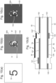
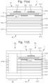
- Figure 4 shows a third example of a security print medium 1 in accordance with the first aspect of the invention.
- the security print medium 1 comprises a core 5 that includes a first core sub-layer 51 and opacifying core sub-layers 53 that defines the first side 5a and second side 5b of the core 5. It also includes a first encoding layer 7a and a second encoding layer 7b, which are each configured in accordance with a predetermined pattern and include pattern elements 41, 43, 45, 47, 49.
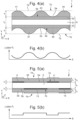
- FIG. 5 shows a cross-sectional view of a fourth example of a security print medium 1 in accordance with the first aspect of the invention.
- the security print medium 1 includes a core 5, which in this example is shown as a single layer but, like the examples discussed above, could include a plurality of sublayers such as those shown in Figures 7(a) to 7(f) , which will be described later.
- the core 5 includes a radiation-responsive substance that produces a predetermined output radiation in response to being irradiated with a predetermined input radiation.
- a first encoding layer 7a comprising pattern elements 9, 11 is disposed on a first side 5a of the core 5, and a second encoding layer 7b comprising pattern elements 13, 15 is disposed on a second side 7b of the core 5.
- the first and second encoding layers 7a, 7b (and hence the arrangement of the elements 9, 11, 13, 15 within them) are configured in accordance with a predetermined pattern.
- the elements 9, 11, 13, 15 in this example are formed of a material that absorbs some or substantially all of the predetermined input and/or output radiation incident on it.
- the elements in this example 9, 11, 13, 15 each have the same thickness h, and as a result the optical density of each encoding layer 7a, 7b varies discretely across the area shown.
- the thicknesses of the elements 9, 11, 13, 15 are equal to one another provided that the optical transmission of the core 5 and first and second encoding layers 7a, 7b in combination is constant across the first region R 1 .
- the optical transmission of the core 5 and first and second encoding layers 7a, 7b in combination is constant across the first region R 1 .
- elements formed of a particular encoding material at a finite thickness are completely opaque to visible light, then their respective optical transmission will not be decreased in a manner perceptible by an observer viewing the security print medium 1 in transmitted visible light by making them thicker by the addition of more of the same encoding material.
- each encoding layer is located between the core 5 and a respective concealing layer 55.
- the concealing layers 55 are each formed of a semi-opaque material that scatters visible light, such as an opacifying coating.
- the two concealing layers 55 are formed of the same semi-opaque material and each have the same thicknesses t 1 , but in other examples the respective concealing layers could be formed of different materials and/or have different dimensions from one another.
- each concealing layer 55 is in direct contact with the core 5 in the spaces between elements 9, 11, 13, 15 in the first or second encoding layer 7a, 7b on its respective side.
- encoding layers could be made planar by the inclusion of an optically transparent material of a thickness h between elements 9, 11, 13, 15, and this would result in the concealing layers 55 also being planar across the extent of the security print medium 1 illustrated.
- the elements 9, 11, 13, 15, and hence the encoding feature defined by the predetermined pattern in accordance with which they are arranged, are not visible when the security print medium 1 is viewed at least in reflected visible light as a result of being hidden by the concealing layers.
- the elements 9, 11, 13, 15 are also concealed when the security print medium 1 is viewed at least in transmitted visible light since the sum of the optical densities of the concealing layers 55, the encoding layers 7a, 7b and the core 5 is constant across the extent of the security print medium 1 shown.
- Figure 5(b) shows the intensity I of output radiation measured from the first side 1a of the security print medium 1 of Figure 5(a) under irradiation with the predetermined input radiation as illustrated in Figure 2(c) .
- the measured intensity I is greater at the positions along the X axis at which the elements 9, 11 in the first encoding layer 7a are not present.
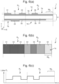
- Figure 6(a) shows a cross-sectional view of a fifth example of a security print medium 1 in accordance with the first aspect of the invention.
- a first region R 1 and a second region R 2 are shown. These regions could, for example, correspond to the first and second regions shown in Figure 1 .
- the security print medium 1 comprises a core 5 that includes a first core-sublayer 51, which in this example is optically transparent, and opacifying core sub-layers 53, which are each formed of a semi-opaque material.
- the security print medium 1 also includes a first encoding layer 7a comprising pattern elements 31, 33, 39 disposed on the first side 5a of the core and a second encoding layer 7b that includes a pattern element 35 disposed on the second side 5b of the core.
- the first and second encoding layers 7a, 7b are configured in accordance with a predetermined pattern and together provide and encoding feature in the security print medium 1.
- the elements 31, 33, 35, 39 are formed of the same semi-opaque material as the opacifying core sub-layers 53.
- the elements 31, 33, 35 are configured in accordance with the predetermined pattern such that the sum of the thicknesses of the first and second encoding layers 7a, 7b (and hence the sum of their optical densities) is constant across the first region R 1 .
- the elements 31, 33, 35 in the first region R 1 are concealed when the security print medium 1 is viewed at least in transmitted visible light.
- the second encoding layer 7b does not include any elements, and thus does not constitute a negative of the first encoding layer 7a.
- a part of the opacifying sub-layer 53 on the second side 5b of the core has been omitted so as to define a half-window W h .
- the opacifying sub-layers 53 could be omitted on both sides of the core 5 in this region, resulting in a transparent window.
- Figure 6(b) shows the appearance of the security print medium 1 of Figure 6(a) when viewed from the first side 1a in transmitted visible light. Since the optical density of the security print medium is constant across the first region R 1 , there is no variation in the intensity of transmitted light between the positions of the elements31, 33, 35 in this region. Moreover, the elements 31, 33, 35 in the first region R 1 are concealed in reflected visible light as a result of appearance of the encoding features being matched to that of the opacifying core sub-layers 53 which define the first side 5a and second side 5b of the core 5.
- the element39 in the second region R 2 is also concealed in reflected visible light for the same reason, it is visible when the security print medium 1 is viewed in transmitted visible light since the optical density of the security print medium 1 on either side of it simply corresponds to that of the two opacifying core sub-layers 53, rather than that of the two opacifying core sub-layers 53 in combination with an encoding feature.
- the predetermined pattern may thus be identifiable in the second region R 2 when the security print medium 1 is viewed in reflected visible light.
- the optical density of the core is further reduced at the location of the half-window W h as a result of the removal of part of the opacifying core sub-layer 53 on the second side 5b of the core 5.
- This configuration thus defines an additional security feature in the form of a pseudo-watermark (preferably a multi-tonal pseudo-watermark) in the second region R 2 .
- Figure 6(c) shows the intensity I of output radiation measured from the first side 1a of the security print medium 1 of Figure 6(a) under irradiation with the predetermined input radiation as illustrated in Figure 2(c) .
- the elements 31, 33, 39 cause the intensity of the output radiation to vary across both the first region R 1 and the second region R 2 .
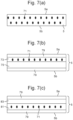
- Figures 7(a) to 7(f) show exemplary configurations of the core 5 suitable for incorporation in security print media according to the first aspect of the invention, and which could be used to implement and of the embodiments described herein.
- the core 5 includes a radiation-responsive substance 71 that responds to a predetermined input radiation by producing a predetermined output radiation.
- the predetermined input radiation and predetermined output radiation may each include one or several respective wavelengths.
- the predetermined input radiation could include one or more ultraviolet wavelengths and the predetermined output radiation could include one or more wavelengths in the infrared.
- the radiation-responsive substances shown in these examples could include one or several such substances each responsive to a different one or more input wavelengths and capable of producing a different one or more output wavelengths.
- the core 5 includes multiple core sub-layers, and in each example these could be produced together (for example by co-extrusion in the molten state) or produced separately and then laminated together.
- the core 5 includes a single layer of material in which the radiation-responsive substance 71 is distributed.
- a security print medium in accordance with the first aspect of the invention incorporating the core 5 of this example could thus include encoding layers disposed directly on the first side 5a and the second side 5b of the core 5.
- This core 5 could, for example, be used to produce a security print medium as shown in Figure 2(a) .
- the core includes a self-supporting sub-layer 75 (which could be included to provide rigidity and/or strength to the security print medium, for example) and the radiation-responsive material is contained in a separate core sub-layer 73 disposed directly on the self-supporting sub-layer.
- Two sub-layers 79 are disposed on the outer sides of the self-supporting polymer sub-layer and the sub-layer 73 containing the radiation-responsive substance 71.
- the sub-layers 79 could each be optically transparent (for example being formed by an optically transparent polymer) or semi-opaque.
- One or both sub-layers 79 could, for example, be an opacifying sub-layer as described above with reference to Figures 3(a) , 4(a) and 6(a) . If the core 5 is to be incorporated in a security print medium in which the encoding features are printed, it is advantageous if the sub-layers 79 are formed of a print-receptive material, and particularly advantageous if these sub-layers 79 of print-receptive material are coextruded with the core 5. Alternatively, the sb-layers 79 could be coated onto the core 5.
- the radiation-responsive substance is contained within a self-supporting sub-layer 81.
- An additional sub-layer 83 is disposed on the self-supporting sub-layer 81.
- the sub-layer 83 could be included to increase the thickness of the core 5 to a desired value, for example.
- coating sub-layers 79 are disposed at the outermost parts of the core 5 and define its first side 5a and second side 5b.
- the sub-layer 83 and the coating sub-layers 79 could each be optically transparent or semi-opaque.
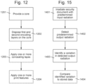
- Figure 12 is a flowchart depicting an exemplary method of manufacturing a security print medium of the sort described above, in accordance with the second aspect of the invention.
- Optional features of the method are indicated by boxes with dashed outlines at steps 1203 and 1204. One, both, or neither of the optional steps may be performed when carrying out the method described.
- Suitable examples of phosphors include, but are not limited to, phosphors that comprises one or more ions capable of emitting IR radiation at one or more wavelengths, such as transition metal-ions including Ti-, Fe-, Ni-, Co-and Cr-ions and lanthanide-ions including Dy-, Nd-, Er-, Pr-, Tm-, Ho-, Yb- and Sm-ions.
- the exciting light can be directly absorbed by an IR-emitting ion.
- Acceptable phosphors also include those that use energy transfer to transfer absorbed energy of the exciting light to the one or more IR-emitting ions such as phosphors comprising sensitizers for absorption (e.g.
- the radiation responsive substance may take the form of particles, pigments or a dye which can be either incorporated into a polymer layer (such as the core or a core sub-layer) during manufacture thereof, e.g. by inclusion into the polymer melt before extruding or casting a film.
- the radiation responsive substance could be dispersed in a solvent or ink carrier and applied to a surface of a suitable core layer, e.g. by printing or coating.
- More than one radiation responsive material can be used in any implementation of the security print media. This may be particularly desirable if more than one output wavelength is to be utilised in the authentication process (described below).
- the encoding material(s) forming the first and second encoding layer can be of any sort which modifies (e.g. amplifies or reduces) the intensity of the input and/or output radiation passing therethrough.
- the material(s) need not modify all wavelengths of the input and/or output radiation, or may modify one wavelength differently to another.
- Preferred examples of encoding materials are those which either scatter or absorb the input and/or output radiation.
- the encoding material will also modify the intensity of other radiation wavelengths, visible and/or non-visible.
- An example of a scattering encoding material is opacifying material, such as white ink.
- the encoding material could comprise a polymeric, non-fibrous material containing at least a light scattering substance such as a pigment.
- the encoding material may comprise a resin such as a polyurethane based resin, polyester based resin or an epoxy based resin and an opacifying pigment such as titanium dioxide (TiO2), silica, zinc oxide, tin oxide, clays or calcium carbonate.
- pigments barium yellow, chrome orange and phthalocyanine blue which each strongly absorb radiation in the range of about 700 nm to 1000 nm
- clay mineral kaolinite, lithophone and gypsum which each absorb strongly in the range of about 1000 nm to 1200 nm.
- the encoding layer can be formed by laser irradiation of a suitably laser-absorbent material, resulting in marked areas which are blackened or foamed relative to the remainder of the material, and hence absorb or scatter the output radiation.
- the relevant layer could be formed of any of the same materials mentioned above in connection with formation of the core 5, but with a laser-markable additive either contained therein or applied thereon.
- Suitable additives may comprise for instance a pigment, preferably antimony oxide or Micabs TM , which is a range of additives supplied by Royal DSM N.V.
- the security medium could comprise ytterbium as the radiation-responsive substance, and one of the above-mentioned IR absorbing materials as the encoding material, e.g. LUNIR5 and LUWSIR4.
- the encoding layers would modify both the input and the output radiation (since ytterbium emits at wavelengths overlapping the absorption peaks of LUNIR5 or LUWSIR4).
- the predetermined pattern would be visible in the output waveband range (around 950 to 1050nm) due to the combined effects of masking of the core by the encoding layer, and attenuation of the emitted output radiation.
- either Er-Yb-KGP or ytterbium could be deployed as the radiation responsive substance, and a scattering encoding material such as a resin comprising TiO 2 particles could be used to form the encoding layers. In both cases the input and output radiation would typically be modified by the encoding layers.
- the concealing layers may for instance be formed of an opacifying material such as that mentioned above for the encoding layer, or a polymer layer of one of the same compositions as mentioned for the core 5, with added opacifying pigment.
- the so-produced medium is ready for onward processing into security documents.
- the medium may be wound into rolls or cut into sheets and supplied to a banknote printer.
- typical onward processing steps include security printing (applying for instance security patterns such as fine line patterns, guilloches etc, denomination data, personalisation data or other graphics, depending on the type of security document to be produced), the application of security articles such as threads, strips, foils or patches, optionally carrying security devices such as holograms or other optical devices (e.g. by hot or cold stamping), the application of security devices directly to the medium, such as diffractive devices or lens-based devices (e.g. by cast-cure), and ultimately cutting the medium into individual security documents.
- security printing applying for instance security patterns such as fine line patterns, guilloches etc, denomination data, personalisation data or other graphics, depending on the type of security document to be produced
- security articles such as threads, strips, foils
- FIG 14 shows an exemplary apparatus for authenticating a security document 1300 comprising a security print medium in accordance with the first aspect of the invention.
- the security document 1300 includes a core 5 that comprises a radiation-responsive substance 71, examples of which are described above with reference to Figure 7(a) to 7(f) .
- the security print document includes an encoding feature provided by a first encoding layer 7a and a second encoding layer 7b each comprising an encoding material.
- the first and second encoding layers 7a, 7b are configured in accordance with a predetermined pattern (such that the combined optical density of the core 5 and the first and second encoding layers 7a, 7b is uniform across the region shown), which defines a plurality of elements 1301 that each modify the observed intensity of the predetermined output radiation produced by the radiation-responsive substance.
- the first and second encoding layers 7a, 7b are each covered by a respective concealing layer 1303 as in, for example, the security print medium of Figure 5 .
- the apparatus described could be used to authenticate security documents comprising any of the security print media described throughout this specification.
- a first radiation source 1305 produces radiation comprising the predetermined input radiation 1317, which is directed towards a first side 1a of security document 1300.
- a second radiation source 1307 irradiates the second side 1b of the security document 1300 with the predetermined input radiation.
- apparatus includes two radiation sources 1305, 1307 (one on either side of the security document 1300), which increases the uniformity with which the core is exposed to the predetermined input radiation. Only one radiation source is required, however, and may be positioned on either side of the security document 1300.
- the radiation sources 1305, 1307 could both produce the same or different profiles of radiation, provided that each outputs the predetermined input radiation 1307. Examples of suitable radiation sources include lasers, LEDs, lamps (for example ultraviolet lamps) and flash-lamps.
- a first filter 1321 is positioned between the second radiation source 1307 and the security print medium 1300.
- the first filter 1317 is configured to partially or entirely block certain wavelengths but permit transmission of wavelengths corresponding to the predetermined input radiation 1317. This can be useful in particular if a significant fraction of the radiation produced by the second radiation source 1307 includes wavelengths corresponding to the predetermined output radiation, for example.
- a second filter 1323 is positioned between the second detector 1313 and the security print medium 1300.
- the second filter 1323 is configured to partially or entirely block certain wavelengths but permit transmission of wavelengths corresponding to the predetermined output radiation 1319. Filters of this kind are particularly useful where the detectors used are responsive to the ambient light or the radiation produced by the radiation source(s).
- the radiation-responsive substance outputs a predetermined output radiation 1319 in response to receiving the predetermined input radiation 1317.
- the output radiation 1319 is absorbed by the elements 1301, thus reducing the intensity of the output radiation on either side of the security document 1300 at the positions of the elements 1301 on the respective side.
- the elements 1301 could comprise an encoding material that additionally or alternatively absorbs, scatters or otherwise modifies the intensity of the predetermined input radiation, and the security print medium could be authenticated by the same methodology described herein.
- a first detector 1309 is positioned to face the first side 1a of the security document 1300.
- the first detector 1309 is configured to detect some or all of the wavelengths included in the predetermined output radiation.
- the detector 1309 in this example is in communication with a first processor 1311, which can receive data from the first detector 1309 and identify variations in the detected radiation (for example absolute or relative variations in the intensity of the detected radiation across the region shown).
- the first processor 1311 may be in communication with a data store and be configured compare the detected output radiation to data from the store.
- the stored data could include, for example, data pertaining to an expected pattern, and the processor could verify or refute the authenticity of the security document based on whether the variations in intensity of the detected radiation match the expected pattern.
- the processor could be configured to output a signal (e.g. to a computer terminal) indicating whether the security document is authentic.
- a second detector 1315 is positioned facing the second side 1b of the security document 1300, and is in communication with a second processor 1315.
- the second processor 1315 may perform any or all of the functions described above with reference to the first processor 1309.
- the second detector could alternatively or additionally be in communication with the first processor 1311.
- the first and/or second processors 1311, 1315 could be configured to compare the variation in intensity of the output radiation detected from either side of the security document 1300.
- the processor(s) 1311, 1315 may be configured to confirm the authenticity of the security document 1300 only if, for example, the output radiation detected on one or both sides of the security document matches an expected pattern.
- two detectors 1309, 1313 are shown. However, only one detector is required, and it may be positioned to face either side of the security document (and may be on the same or opposite side to the radiation source(s) 1305, 1307).
- the detector(s) 1309, 1315 may be in operation while the security document 1300 is irradiated with the predetermined input radiation 1317. This could be the case if, for example, the radiation-responsive substance 71 exhibits fluorescence. If the response of the radiation-responsive substance 71 is delayed (i.e. the luminescent substance produces or continues to produce the predetermined output radiation after being irradiated with the predetermined input radiation 1317), however, the radiation source(s) 1305, 1307 may be switched off before the detectors begin to detect the predetermined output radiation 1319. This could be the case if the radiation-responsive substance exhibits phosphorescence, for example.
- FIG 15 is a flowchart for a method of authenticating a security document comprising a security print medium in accordance with the first aspect of the invention.
- An optional step 1404 is indicated by a box with a dashed outline. This method may be performed using some or all of the apparatus described above with reference to Figure 14 , and the security document being authenticated could, for example, comprise a security print medium as described in any of Figures 2 to 6 or 8 to 11 .
- the security document is irradiated with the predetermined input radiation.
- the source of the predetermined input radiation could be positioned on one or both sides of the security document. This causes a radiation responsive-substance in a core of the security document to produce a predetermined output radiation, the intensity of which is modified by an encoding material contained in first and second encoding layers that are each configured in accordance with a predetermined pattern (such that the combined optical density of the core and the first and second encoding layers is uniform across a first region of the security document) and are disposed on first and second sides of the core respectively.
- the predetermined output radiation is detected from at least one side of the security document. This may be performed using one or more detectors as described above, for example, each positioned on either side of the security document.
- a variation in the detected output radiation is identified. This step could involve measuring a relative variation in the intensity between different positions across the security document (e.g. by determining that the intensity recorded at one position is a particular fraction of that at another) and/or differences between absolute values of the intensity at different positions. The authenticity of the security document may be confirmed or refuted based on the identified variation in the detected output radiation.
- the variation(s) in the intensity of the detected radiation identified at step 1403 are compared to stored data, which may include data indicating how the intensity of the detected output radiation is expected to vary across the security document. It could also include expected absolute values of the intensity at particular locations on the security document.
Landscapes
- Engineering & Computer Science (AREA)
- Physics & Mathematics (AREA)
- General Physics & Mathematics (AREA)
- Manufacturing & Machinery (AREA)
- Finance (AREA)
- Accounting & Taxation (AREA)
- Business, Economics & Management (AREA)
- Computer Vision & Pattern Recognition (AREA)
- Computer Security & Cryptography (AREA)
- Health & Medical Sciences (AREA)
- General Health & Medical Sciences (AREA)
- Toxicology (AREA)
- Spectroscopy & Molecular Physics (AREA)
- Credit Cards Or The Like (AREA)
- Printing Methods (AREA)
Claims (21)
- Sicherheitsdruckmedium zum Bilden von Sicherheitsdokumenten daraus, wobei das Sicherheitsdruckmedium (1) umfasst:einen Kern (5), der eine erste und eine zweite Seite (5a, 5b) aufweist, die einander gegenüberliegen, wobei der Kern eine auf Strahlung reagierende Substanz umfasst, die innerhalb des Kerns über mindestens einen ersten Bereich (R1) des Kerns hinweg verteilt ist, wobei die auf Strahlung reagierende Substanz auf eine vorbestimmte Eingangsstrahlung durch Erzeugen einer vorbestimmten Ausgangsstrahlung reagiert;eine erste Codierungsschicht (7a), die auf der ersten Seite des Kerns angeordnet ist, und eine zweite Codierungsschicht (7b), die auf der zweiten Seite des Kerns angeordnet ist, wobei jede der ersten und der zweiten Codierungsschicht (7a, 7b) ein Codierungsmaterial umfasst, das die Intensität der vorbestimmten Eingangsstrahlung und/oder der von der auf Strahlung reagierenden Substanz erzeugten vorbestimmten Ausgangsstrahlung, die durch die jeweilige Codierungsschicht durchgelassen wird, modifiziert, wobei die erste und die zweite Codierungsschicht (7a, 7b) einander über den ersten Bereich (R1) hinweg überlappen;wobei die optische Dichte jeder der ersten und der zweiten Codierungsschicht (7a, 7b) über den ersten Bereich (R1) hinweg in Übereinstimmung mit einem vorbestimmten Muster variiert, wobei das vorbestimmte Muster ein oder mehrere Codierungsmerkmale definiert, derart, dass, wenn das Sicherheitsdruckmedium (1) der vorbestimmten Eingangsstrahlung ausgesetzt wird, die von einer oder jeder Seite des Sicherheitsdruckmediums (1) her erfassbare Ausgangsstrahlung über den ersten Bereich (R1) hinweg in Übereinstimmung mit dem einen oder den mehreren Codierungsmerkmalen variiert, und die erste und die zweite Codierungsschicht (7a, 7b) derart konfiguriert sind, dass, wenn das Sicherheitsdruckmedium (1) in durchgelassenem sichtbarem Licht betrachtet wird, die Intensität von sichtbarem Licht, das durch die erste Codierungsschicht (7a), den Kern (5) und die zweite Codierungsschicht (7b) in Kombination durchgelassen wird, über den ersten Bereich (R1) hinweg gleichmäßig ist, derart, dass das eine oder die mehreren Codierungsmerkmale kaschiert werden.
- Sicherheitsdruckmedium nach Anspruch 1, wobei das eine oder die mehreren Codierungsmerkmale, wenn das Sicherheitsdruckmedium in reflektiertem sichtbarem Licht von einer oder jeder Seite her betrachtet wird, entweder infolgedessen, dass (i) eine oder mehrere Kaschierschichten jeweils so angeordnet sind, dass sie eine jeweilige der ersten und der zweiten Codierungsschicht in reflektiertem sichtbarem Licht verbergen, oder (ii) das visuelle Erscheinungsbild des Kerns und einer oder beider der ersten und der zweiten Codierungsschicht derart konfiguriert sind, dass das vorbestimmte Muster kaschiert wird, wenn es in reflektiertem sichtbarem Licht betrachtet wird, kaschiert werden.
- Sicherheitsdruckmedium nach Anspruch 1 oder 2, wobei:das visuelle Erscheinungsbild der ersten Codierungsschicht so konfiguriert ist, dass es mit dem visuellen Erscheinungsbild des Kerns übereinstimmt, wenn es von der ersten Seite her betrachtet wird, derart, dass das eine oder die mehreren Codierungsmerkmale kaschiert werden, wenn das Sicherheitsdruckmedium in reflektiertem sichtbarem Licht von der ersten Seite her betrachtet wird; und/oderdas visuelle Erscheinungsbild der zweiten Codierungsschicht so konfiguriert ist, dass es mit dem visuellen Erscheinungsbild des Kerns übereinstimmt, wenn es von der zweiten Seite her betrachtet wird, derart, dass das eine oder die mehreren Codierungsmerkmale kaschiert werden, wenn das Sicherheitsdruckmedium in reflektiertem sichtbarem Licht von der zweiten Seite her betrachtet wird.
- Sicherheitsdruckmedium nach Anspruch 1 oder 2, wobei der Kern im ersten Bereich für sichtbares Licht durchlässig ist und das vorbestimmte Muster derart konfiguriert ist, dass, wenn das Sicherheitsdruckmedium in reflektiertem sichtbarem Licht betrachtet wird, das Codierungsmaterial an jeder Position im ersten Bereich sichtbar ist, um das vorbestimmte Muster zu kaschieren.
- Sicherheitsdruckmedium nach einem der vorstehenden Ansprüche, das eine erste Kaschierschicht, die auf der ersten Seite des Kerns angeordnet ist, und/oder eine zweite Kaschierschicht, die auf der zweiten Seite des Kerns angeordnet ist, umfasst, wobei die oder jede Kaschierschicht ein halbtrübes Material umfasst, wobei die oder jede Kaschierschicht über den ersten Bereich hinweg eine konstante optische Dichte aufweist und wobei die oder jede Kaschierschicht die erste und die zweite Codierungsschicht über den ersten Bereich hinweg überlappt, um die Codierungsschichten von mindestens einer Seite des Sicherheitsdruckmediums her zu kaschieren, wenn es in reflektiertem sichtbarem Licht betrachtet wird, und wobei vorzugsweise die oder jede Kaschierschicht eine Trübungschicht ist;
wobei vorzugsweise das Codierungsmaterial dasselbe Material ist wie das halbtrübe Material, das die eine oder die mehreren Kaschierschichten umfassen. - Sicherheitsdruckmedium nach einem der vorstehenden Ansprüche, wobei die Summe der optischen Dichten der ersten und der zweiten Codierungsschicht über den ersten Bereich hinweg konstant ist.
- Sicherheitsdruckmedium nach einem der vorstehenden Ansprüche, wobei an einer oder mehreren Positionen im ersten Bereich die optische Dichte der ersten Codierungsschicht oder der zweiten Codierungsschicht null ist.
- Sicherheitsdruckmedium nach einem der vorstehenden Ansprüche, wobei:die erste Codierungsschicht und/oder die zweite Codierungsschicht eine jeweilige Schicht aus strahlungsmarkierbarem Material umfasst, in der ein oder mehrere Musterelemente des vorbestimmten Musters gebildet sind, die durch Bestrahlung des strahlungsmarkierbaren Materials erzeugt wurden, und/oderdie erste und/oder die zweite Codierungsschicht in Übereinstimmung mit dem vorbestimmten Muster, vorzugsweise durch Tintenstrahl-, Intaglio-oder Tiefdruck, gedruckt ist.
- Sicherheitsdruckmedium nach einem der vorstehenden Ansprüche, wobei das vorbestimmte Muster Musterelemente unterschiedlicher optischer Dichtestufen beinhaltet, wobei die minimalen seitlichen Abmessungen der Musterelemente größer sind als die Dicke des Kerns, vorzugsweise mindestens das 10fache der Dicke des Kerns betragen.
- Sicherheitsdruckmedium nach einem der vorstehenden Ansprüche, wobei die jeweilige Dicke jeder der ersten und der zweiten Codierungsschicht in Übereinstimmung mit dem vorbestimmten Muster variiert, um die variierende optische Dichte jeder der ersten und der zweiten Codierungsschicht bereitzustellen,
wobei vorzugsweise die Summe der Dicke der ersten Codierungsschicht und der Dicke der zweiten Codierungsschicht über den ersten Bereich hinweg konstant ist. - Sicherheitsdruckmedium nach einem der vorstehenden Ansprüche, wobei die vorbestimmte Eingangsstrahlung, auf die die auf Strahlung reagierende Substanz reagiert, und/oder die von der auf Strahlung reagierenden Substanz erzeugte vorbestimmte Ausgangsstrahlung außerhalb des sichtbaren Spektrums liegt/liegen.
- Sicherheitsdruckmedium nach einem der vorstehenden Ansprüche, wobeidie vorbestimmte Eingangsstrahlung, auf die die auf Strahlung reagierende Substanz reagiert, eine Vielzahl von Eingangswellenlängen umfasst; und/oderdie von der auf Strahlung reagierenden Substanz als Reaktion auf die vorbestimmte Eingangsstrahlung erzeugte vorbestimmte Ausgangsstrahlung eine Vielzahl von Ausgangswellenlängen umfasst.
- Sicherheitsdruckmedium nach Anspruch 12, wobei die vorbestimmte Eingangsstrahlung eine Vielzahl von Eingangswellenlängen umfasst und die erste Codierungsschicht und/oder die zweite Codierungsschicht die Intensität einer ersten der Vielzahl von Eingangswellenlängen modifiziert, aber nicht die Intensität einer zweiten der Vielzahl von Eingangswellenlängen modifiziert, oder diese anderweitig modifiziert.
- Sicherheitsdruckmedium nach Anspruch 12 oder Anspruch 13, wobei die von der auf Strahlung reagierenden Substanz als Reaktion auf die vorbestimmte Eingangsstrahlung erzeugte vorbestimmte Ausgangsstrahlung eine Vielzahl von Ausgangswellenlängen umfasst, und die erste Codierungsschicht und/oder die zweite Codierungsschicht die Intensität einer ersten der Vielzahl von Ausgangswellenlängen modifiziert, aber nicht die Intensität einer zweiten der Vielzahl von Ausgangswellenlängen modifiziert, oder diese anderweitig modifiziert.
- Sicherheitsdruckmedium nach einem der vorstehenden Ansprüche, das im ersten Bereich weiter ein oder mehrere Druckmerkmale umfasst, die jeweils angeordnet sind auf:der ersten Seite des Kerns, der ersten Codierungsschicht und, sofern bereitgestellt, der ersten Kaschierschicht, die sich zwischen dem ersten Druckmerkmal und dem Kern befindet; oderder zweiten Seite des Kerns, der zweiten Codierungsschicht und, sofern bereitgestellt, der zweiten Kaschierschicht, die sich zwischen dem zweiten Druckmerkmal und dem Kern befindet;wobei vorzugsweise jedes des einen oder der mehreren Druckmerkmale so konfiguriert ist, dass es sichtbar ist, wenn es in reflektiertem sichtbarem Licht von der jeweiligen Seite des Kerns, auf der es angeordnet ist, betrachtet wird.
- Sicherheitsdruckmedium nach Anspruch 15, wobei das eine oder die mehreren Druckmerkmale jeweils ein Material umfassen, das die vorbestimmte Eingangsstrahlung und/oder die vorbestimmte Ausgangsstrahlung absorbiert und/oder streut;
wobei vorzugsweise das vorbestimmte Muster weiter im ersten Bereich ein Kompensationsmerkmal definiert, wobei das Kompensationsmerkmal so konfiguriert ist, dass es das Druckmerkmal derart kompensiert, dass die durch die erste Codierungsschicht und das Druckmerkmal durchgelassene vorbestimmte Ausgangsstrahlung nicht in Übereinstimmung mit dem Druckmerkmal variiert. - Sicherheitsdruckmedium nach einem der vorstehenden Ansprüche, wobei das vorbestimmte Muster so konfiguriert ist, dass es in einer oder beiden der ersten und der zweiten Codierungsschicht ein oder mehrere codierte Muster definiert, wobei jedes codierte Muster vorzugsweise eines oder mehrere von einem Bild, einer alphanumerischen Folge und einem maschinenlesbaren Code umfasst, wobei der maschinenlesbare Code vorzugsweise einen Strichcode und/oder einen Mehrbitcode umfasst;
wobei vorzugsweise mindestens eines der codierten Muster eine eindeutige Seriennummer darstellt. - Sicherheitsdokument, das das Sicherheitsdruckmedium nach einem der Ansprüche 1-17 umfasst.
- Verfahren zum Herstellen eines Sicherheitsdruckmediums, wobei das Verfahren umfasst:(a) Bereitstellen eines Kerns (5), der eine erste und eine zweite Seite (5a, 5b) aufweist, die einander gegenüberliegen, wobei der Kern eine auf Strahlung reagierende Substanz umfasst, die innerhalb des Kerns über mindestens einen ersten Bereich (R1) des Kerns hinweg verteilt ist, wobei die auf Strahlung reagierende Substanz auf eine vorbestimmte Eingangsstrahlung durch Erzeugen einer vorbestimmten Ausgangsstrahlung reagiert; und(b) Anordnen einer ersten Codierungsschicht (7a) auf der ersten Seite (5a) des Kerns (5), und Anordnen einer zweiten Codierungsschicht (7b) auf der zweiten Seite (5b) des Kerns (5), wobei jede der ersten und der zweiten Codierungsschicht (7a, 7b) ein Codierungsmaterial umfasst, das die Intensität der vorbestimmten Eingangsstrahlung und/oder der von der auf Strahlung reagierenden Substanz erzeugten vorbestimmten Ausgangsstrahlung, die durch die jeweilige Codierungsschicht durchgelassen wird, modifiziert, wobei die erste und die zweite Codierungsschicht (7a, 7b) einander über den ersten Bereich hinweg überlappen;wobei die optische Dichte jeder der ersten und der zweiten Codierungsschicht (7a, 7b) über den ersten Bereich (R1) hinweg in Übereinstimmung mit einem vorbestimmten Muster variiert, wobei das vorbestimmte Muster ein oder mehrere Codierungsmerkmale definiert, derart, dass, wenn das Sicherheitsdruckmedium (1) der vorbestimmten Eingangsstrahlung ausgesetzt wird, die von einer oder jeder Seite des Sicherheitsdruckmediums (1) her erfassbare Ausgangsstrahlung über den ersten Bereich (R1) hinweg in Übereinstimmung mit dem einen oder den mehreren Codierungsmerkmalen variiert, und die erste und die zweite Codierungsschicht (7a, 7b) derart konfiguriert sind, dass, wenn das Sicherheitsdruckmedium (1) in durchgelassenem sichtbarem Licht betrachtet wird, die Intensität von sichtbarem Licht, das durch die erste Codierungsschicht (7a), den Kern (5) und die zweite Codierungsschicht (7b) in Kombination durchgelassen wird, über den ersten Bereich (R1) hinweg gleichmäßig ist, derart, dass das eine oder die mehreren Codierungsmerkmale kaschiert werden.
- Verfahren zum Authentifizieren des Sicherheitsdokuments nach Anspruch 18, wobei das Verfahren umfasst:(a) Bestrahlen des ersten Bereichs des Sicherheitsdokuments (1300) mit der vorbestimmten Eingangsstrahlung von einer ersten Seite (1a) des Sicherheitsdokuments (1300) her;(b) Erfassen, von der ersten Seite (1a) und/oder einer zweiten Seite (1b) her, der vorbestimmten Ausgangsstrahlung, die von der auf Strahlung reagierenden Substanz abgegeben wird; und(c) Identifizieren einer Variation in der erfassten Ausgangsstrahlung.
- Einrichtung zum Authentifizieren des Sicherheitsdokuments nach Anspruch 18, wobei die Einrichtung umfasst:eine Strahlungsquelle, die so konfiguriert ist, dass sie eine erste Seite (1a) des Sicherheitsdokuments (1300) mit der vorbestimmten Eingangsstrahlung bestrahlt;einen oder mehrere Detektoren, die jeweils so konfiguriert sind, dass sie die vorbestimmte Ausgangsstrahlung, die von einer ersten (1a) und/oder zweiten Seite (1b) des Sicherheitsdokuments (1300) her abgegeben wird, erfassen;einen Prozessor (1311) in Kommunikation mit dem einen oder den mehreren Detektoren, wobei der Prozessor (1311) so konfiguriert ist, dass er eine Variation in der erfassten Ausgangsstrahlung identifiziert.
Applications Claiming Priority (2)
| Application Number | Priority Date | Filing Date | Title |
|---|---|---|---|
| GB1914921.0A GB2588205B (en) | 2019-10-15 | 2019-10-15 | Security print media |
| PCT/GB2020/052483 WO2021074591A1 (en) | 2019-10-15 | 2020-10-08 | Security print media |
Publications (3)
| Publication Number | Publication Date |
|---|---|
| EP4045329A1 EP4045329A1 (de) | 2022-08-24 |
| EP4045329B1 true EP4045329B1 (de) | 2025-07-02 |
| EP4045329C0 EP4045329C0 (de) | 2025-07-02 |
Family
ID=68619662
Family Applications (1)
| Application Number | Title | Priority Date | Filing Date |
|---|---|---|---|
| EP20793065.2A Active EP4045329B1 (de) | 2019-10-15 | 2020-10-08 | Sicherheitsdruckmedien |
Country Status (8)
| Country | Link |
|---|---|
| US (1) | US11887427B2 (de) |
| EP (1) | EP4045329B1 (de) |
| CN (1) | CN114340907B (de) |
| AU (1) | AU2020368043B2 (de) |
| GB (1) | GB2588205B (de) |
| MX (1) | MX2022002376A (de) |
| PH (1) | PH12022550342A1 (de) |
| WO (1) | WO2021074591A1 (de) |
Families Citing this family (2)
| Publication number | Priority date | Publication date | Assignee | Title |
|---|---|---|---|---|
| GB2613016B (en) * | 2021-11-22 | 2024-03-13 | De La Rue Int Ltd | A method of manufacturing a security sheet |
| DE102022129534A1 (de) * | 2022-11-08 | 2024-05-08 | Bundesdruckerei Gmbh | Verfahren zum Bedrucken eines Dokuments |
Family Cites Families (14)
| Publication number | Priority date | Publication date | Assignee | Title |
|---|---|---|---|---|
| RU2006115591A (ru) | 2003-10-09 | 2007-11-27 | Секьюренси Пти Лимитед (Au) | Защищенный документ с преобразующим с повышением частоты материалом |
| GB2452078B (en) * | 2007-08-23 | 2009-12-23 | Rue De Int Ltd | Security devices for security substrates |
| CA2656506A1 (en) * | 2009-02-27 | 2010-08-27 | Bank Of Canada | Security device |
| FR2942899B1 (fr) * | 2009-03-03 | 2011-09-23 | Jose Balbuena | Dispositif et procede d'analyse optique de documents |
| JP5601040B2 (ja) * | 2010-06-08 | 2014-10-08 | 凸版印刷株式会社 | 偽造防止媒体 |
| US10275969B2 (en) * | 2012-03-09 | 2019-04-30 | United States Postal Service | Method and system for item authentication and customization |
| US20130300101A1 (en) * | 2012-05-11 | 2013-11-14 | Document Security Systems, Inc. | Laminated Documents and Cards Including Embedded Security Features |
| GB201212046D0 (en) * | 2012-07-06 | 2012-08-22 | Rue De Int Ltd | Security devices |
| US10650630B2 (en) * | 2014-10-31 | 2020-05-12 | Honeywell International Inc. | Authentication systems, authentication devices, and methods for authenticating a value article |
| FR3030856B1 (fr) * | 2014-12-19 | 2018-02-02 | Arjobex | Etiquette adhesive |
| GB201512118D0 (en) * | 2015-07-10 | 2015-08-19 | Rue De Int Ltd | Methods of manufacturing security documents and security devices |
| GB2542786B (en) * | 2015-09-29 | 2018-02-28 | De La Rue Int Ltd | Security print media and method of manufacture thereof |
| DE102015015991A1 (de) * | 2015-12-10 | 2017-06-14 | Giesecke & Devrient Gmbh | Sicherheitselement mit Linsenrasterbild |
| JP2017220084A (ja) * | 2016-06-09 | 2017-12-14 | 凸版印刷株式会社 | ライトアップカード |
-
2019
- 2019-10-15 GB GB1914921.0A patent/GB2588205B/en active Active
-
2020
- 2020-10-08 PH PH1/2022/550342A patent/PH12022550342A1/en unknown
- 2020-10-08 EP EP20793065.2A patent/EP4045329B1/de active Active
- 2020-10-08 WO PCT/GB2020/052483 patent/WO2021074591A1/en not_active Ceased
- 2020-10-08 CN CN202080061040.0A patent/CN114340907B/zh active Active
- 2020-10-08 US US17/634,743 patent/US11887427B2/en active Active
- 2020-10-08 AU AU2020368043A patent/AU2020368043B2/en active Active
- 2020-10-08 MX MX2022002376A patent/MX2022002376A/es unknown
Also Published As
| Publication number | Publication date |
|---|---|
| GB201914921D0 (en) | 2019-11-27 |
| GB2588205B (en) | 2021-12-22 |
| US20220284753A1 (en) | 2022-09-08 |
| AU2020368043A1 (en) | 2022-03-10 |
| US11887427B2 (en) | 2024-01-30 |
| GB2588205A (en) | 2021-04-21 |
| EP4045329C0 (de) | 2025-07-02 |
| EP4045329A1 (de) | 2022-08-24 |
| CN114340907A (zh) | 2022-04-12 |
| WO2021074591A1 (en) | 2021-04-22 |
| MX2022002376A (es) | 2022-04-01 |
| PH12022550342A1 (en) | 2023-02-20 |
| CN114340907B (zh) | 2024-06-18 |
| AU2020368043B2 (en) | 2026-03-12 |
Similar Documents
| Publication | Publication Date | Title |
|---|---|---|
| KR102488710B1 (ko) | 적층체, 신분증명서, 및, 신분증명서의 검증 방법 | |
| CN1099968C (zh) | 安全证件 | |
| EP1719637B1 (de) | Sicherheitsdokument mit UV Echtheitsmerkmal und Verfahren um ein Echtheitsmerkmal auf ein Sicherheitsdokument aufzubringen. | |
| EP0988157B1 (de) | Verfahren zum herstellen und zum prüfen eines sicherheitspapiers | |
| US20140151996A1 (en) | Element for security document comprising an optical structure | |
| US10535211B2 (en) | Method and system for item authentication and customization | |
| HUT67614A (en) | Identification article | |
| EP3192665B1 (de) | Verfahren und system zur gegenstandsauthentifizierung und -personalisierung | |
| PL238769B1 (pl) | Dokument zabezpieczony z elementem zabezpieczającym, sposób wytwarzania dokumentu zabezpieczonego oraz element zabezpieczający | |
| EP4045329B1 (de) | Sicherheitsdruckmedien | |
| WO2023037087A1 (en) | Security devices and methods of manufacture thereof | |
| CN120225366A (zh) | 具有机器可读的防伪特征的数据载体、制造方法和防伪基材页幅 | |
| JP7268472B2 (ja) | 偽造防止媒体および真贋判定方法 | |
| OA21531A (en) | Security document with UV-absorbing security element. | |
| HK1058507A (en) | Antifalsification paper and security document produced therefrom | |
| HK1058507B (en) | Antifalsification paper and security document produced therefrom |
Legal Events
| Date | Code | Title | Description |
|---|---|---|---|
| STAA | Information on the status of an ep patent application or granted ep patent |
Free format text: STATUS: UNKNOWN |
|
| STAA | Information on the status of an ep patent application or granted ep patent |
Free format text: STATUS: THE INTERNATIONAL PUBLICATION HAS BEEN MADE |
|
| PUAI | Public reference made under article 153(3) epc to a published international application that has entered the european phase |
Free format text: ORIGINAL CODE: 0009012 |
|
| STAA | Information on the status of an ep patent application or granted ep patent |
Free format text: STATUS: REQUEST FOR EXAMINATION WAS MADE |
|
| 17P | Request for examination filed |
Effective date: 20220223 |
|
| AK | Designated contracting states |
Kind code of ref document: A1 Designated state(s): AL AT BE BG CH CY CZ DE DK EE ES FI FR GB GR HR HU IE IS IT LI LT LU LV MC MK MT NL NO PL PT RO RS SE SI SK SM TR |
|
| DAV | Request for validation of the european patent (deleted) | ||
| DAX | Request for extension of the european patent (deleted) | ||
| GRAP | Despatch of communication of intention to grant a patent |
Free format text: ORIGINAL CODE: EPIDOSNIGR1 |
|
| STAA | Information on the status of an ep patent application or granted ep patent |
Free format text: STATUS: GRANT OF PATENT IS INTENDED |
|
| INTG | Intention to grant announced |
Effective date: 20241115 |
|
| GRAJ | Information related to disapproval of communication of intention to grant by the applicant or resumption of examination proceedings by the epo deleted |
Free format text: ORIGINAL CODE: EPIDOSDIGR1 |
|
| STAA | Information on the status of an ep patent application or granted ep patent |
Free format text: STATUS: REQUEST FOR EXAMINATION WAS MADE |
|
| INTC | Intention to grant announced (deleted) | ||
| GRAP | Despatch of communication of intention to grant a patent |
Free format text: ORIGINAL CODE: EPIDOSNIGR1 |
|
| STAA | Information on the status of an ep patent application or granted ep patent |
Free format text: STATUS: GRANT OF PATENT IS INTENDED |
|
| GRAS | Grant fee paid |
Free format text: ORIGINAL CODE: EPIDOSNIGR3 |
|
| GRAA | (expected) grant |
Free format text: ORIGINAL CODE: 0009210 |
|
| STAA | Information on the status of an ep patent application or granted ep patent |
Free format text: STATUS: THE PATENT HAS BEEN GRANTED |
|
| INTG | Intention to grant announced |
Effective date: 20250512 |
|
| AK | Designated contracting states |
Kind code of ref document: B1 Designated state(s): AL AT BE BG CH CY CZ DE DK EE ES FI FR GR HR HU IE IS IT LI LT LU LV MC MK MT NL NO PL PT RO RS SE SI SK SM TR |
|
| RBV | Designated contracting states (corrected) |
Designated state(s): AL AT BE BG CH CY CZ DE DK EE ES FI FR GR HR HU IE IS IT LI LT LU LV MC MK MT NL NO PL PT RO RS SE SI SK SM TR |
|
| REG | Reference to a national code |
Ref country code: CH Ref legal event code: EP |
|
| REG | Reference to a national code |
Ref country code: DE Ref legal event code: R096 Ref document number: 602020053877 Country of ref document: DE |
|
| REG | Reference to a national code |
Ref country code: IE Ref legal event code: FG4D |
|
| U01 | Request for unitary effect filed |
Effective date: 20250715 |
|
| U07 | Unitary effect registered |
Designated state(s): AT BE BG DE DK EE FI FR IT LT LU LV MT NL PT RO SE SI Effective date: 20250721 |
|
| U20 | Renewal fee for the european patent with unitary effect paid |
Year of fee payment: 6 Effective date: 20250909 |
|
| REG | Reference to a national code |
Ref country code: CH Ref legal event code: U11 Free format text: ST27 STATUS EVENT CODE: U-0-0-U10-U11 (AS PROVIDED BY THE NATIONAL OFFICE) Effective date: 20251101 |
|
| PG25 | Lapsed in a contracting state [announced via postgrant information from national office to epo] |
Ref country code: IS Free format text: LAPSE BECAUSE OF FAILURE TO SUBMIT A TRANSLATION OF THE DESCRIPTION OR TO PAY THE FEE WITHIN THE PRESCRIBED TIME-LIMIT Effective date: 20251102 |
|
| PG25 | Lapsed in a contracting state [announced via postgrant information from national office to epo] |
Ref country code: NO Free format text: LAPSE BECAUSE OF FAILURE TO SUBMIT A TRANSLATION OF THE DESCRIPTION OR TO PAY THE FEE WITHIN THE PRESCRIBED TIME-LIMIT Effective date: 20251002 |
|
| PG25 | Lapsed in a contracting state [announced via postgrant information from national office to epo] |
Ref country code: HR Free format text: LAPSE BECAUSE OF FAILURE TO SUBMIT A TRANSLATION OF THE DESCRIPTION OR TO PAY THE FEE WITHIN THE PRESCRIBED TIME-LIMIT Effective date: 20250702 |
|
| PG25 | Lapsed in a contracting state [announced via postgrant information from national office to epo] |
Ref country code: GR Free format text: LAPSE BECAUSE OF FAILURE TO SUBMIT A TRANSLATION OF THE DESCRIPTION OR TO PAY THE FEE WITHIN THE PRESCRIBED TIME-LIMIT Effective date: 20251003 |
|
| PGFP | Annual fee paid to national office [announced via postgrant information from national office to epo] |
Ref country code: CH Payment date: 20251101 Year of fee payment: 6 |
|
| PG25 | Lapsed in a contracting state [announced via postgrant information from national office to epo] |
Ref country code: CZ Free format text: LAPSE BECAUSE OF FAILURE TO SUBMIT A TRANSLATION OF THE DESCRIPTION OR TO PAY THE FEE WITHIN THE PRESCRIBED TIME-LIMIT Effective date: 20250702 |
|
| PG25 | Lapsed in a contracting state [announced via postgrant information from national office to epo] |
Ref country code: PL Free format text: LAPSE BECAUSE OF FAILURE TO SUBMIT A TRANSLATION OF THE DESCRIPTION OR TO PAY THE FEE WITHIN THE PRESCRIBED TIME-LIMIT Effective date: 20250702 |
|
| PG25 | Lapsed in a contracting state [announced via postgrant information from national office to epo] |
Ref country code: RS Free format text: LAPSE BECAUSE OF FAILURE TO SUBMIT A TRANSLATION OF THE DESCRIPTION OR TO PAY THE FEE WITHIN THE PRESCRIBED TIME-LIMIT Effective date: 20251002 |
|
| PG25 | Lapsed in a contracting state [announced via postgrant information from national office to epo] |
Ref country code: ES Free format text: LAPSE BECAUSE OF FAILURE TO SUBMIT A TRANSLATION OF THE DESCRIPTION OR TO PAY THE FEE WITHIN THE PRESCRIBED TIME-LIMIT Effective date: 20250702 |