EP4044837B1 - Dispositif de génération d'aérosol comportant des composants modulaires - Google Patents
Dispositif de génération d'aérosol comportant des composants modulaires Download PDFInfo
- Publication number
- EP4044837B1 EP4044837B1 EP20793181.7A EP20793181A EP4044837B1 EP 4044837 B1 EP4044837 B1 EP 4044837B1 EP 20793181 A EP20793181 A EP 20793181A EP 4044837 B1 EP4044837 B1 EP 4044837B1
- Authority
- EP
- European Patent Office
- Prior art keywords
- module
- aerosol generating
- generating device
- aerosol
- housing
- Prior art date
- Legal status (The legal status is an assumption and is not a legal conclusion. Google has not performed a legal analysis and makes no representation as to the accuracy of the status listed.)
- Active
Links
- 239000000443 aerosol Substances 0.000 title claims description 204
- 239000000758 substrate Substances 0.000 claims description 40
- SNICXCGAKADSCV-JTQLQIEISA-N (-)-Nicotine Chemical compound CN1CCC[C@H]1C1=CC=CN=C1 SNICXCGAKADSCV-JTQLQIEISA-N 0.000 claims description 7
- 230000008878 coupling Effects 0.000 claims description 7
- 238000010168 coupling process Methods 0.000 claims description 7
- 238000005859 coupling reaction Methods 0.000 claims description 7
- 229960002715 nicotine Drugs 0.000 claims description 7
- SNICXCGAKADSCV-UHFFFAOYSA-N nicotine Natural products CN1CCCC1C1=CC=CN=C1 SNICXCGAKADSCV-UHFFFAOYSA-N 0.000 claims description 7
- 238000004891 communication Methods 0.000 claims description 6
- 241000208125 Nicotiana Species 0.000 claims description 3
- 235000002637 Nicotiana tabacum Nutrition 0.000 claims description 3
- 238000010438 heat treatment Methods 0.000 description 17
- 238000000034 method Methods 0.000 description 13
- 230000006870 function Effects 0.000 description 11
- 238000012546 transfer Methods 0.000 description 7
- 238000013500 data storage Methods 0.000 description 6
- 230000008569 process Effects 0.000 description 6
- 230000007246 mechanism Effects 0.000 description 5
- 238000012545 processing Methods 0.000 description 5
- 239000000470 constituent Substances 0.000 description 4
- 230000006698 induction Effects 0.000 description 4
- 239000007788 liquid Substances 0.000 description 4
- 239000000843 powder Substances 0.000 description 4
- 238000010897 surface acoustic wave method Methods 0.000 description 4
- 238000004590 computer program Methods 0.000 description 3
- 239000002245 particle Substances 0.000 description 3
- 150000001875 compounds Chemical class 0.000 description 2
- 239000004020 conductor Substances 0.000 description 2
- 238000005516 engineering process Methods 0.000 description 2
- 230000001939 inductive effect Effects 0.000 description 2
- 239000000463 material Substances 0.000 description 2
- 230000003287 optical effect Effects 0.000 description 2
- 230000001681 protective effect Effects 0.000 description 2
- 239000000853 adhesive Substances 0.000 description 1
- 230000001070 adhesive effect Effects 0.000 description 1
- 239000002390 adhesive tape Substances 0.000 description 1
- XAGFODPZIPBFFR-UHFFFAOYSA-N aluminium Chemical compound [Al] XAGFODPZIPBFFR-UHFFFAOYSA-N 0.000 description 1
- 229910052782 aluminium Inorganic materials 0.000 description 1
- 239000004411 aluminium Substances 0.000 description 1
- 238000003491 array Methods 0.000 description 1
- 230000015572 biosynthetic process Effects 0.000 description 1
- 230000001413 cellular effect Effects 0.000 description 1
- 238000006243 chemical reaction Methods 0.000 description 1
- QVFWZNCVPCJQOP-UHFFFAOYSA-N chloralodol Chemical compound CC(O)(C)CC(C)OC(O)C(Cl)(Cl)Cl QVFWZNCVPCJQOP-UHFFFAOYSA-N 0.000 description 1
- 235000019504 cigarettes Nutrition 0.000 description 1
- 238000007906 compression Methods 0.000 description 1
- 230000006835 compression Effects 0.000 description 1
- 238000013144 data compression Methods 0.000 description 1
- 230000000694 effects Effects 0.000 description 1
- 239000000796 flavoring agent Substances 0.000 description 1
- 235000019634 flavors Nutrition 0.000 description 1
- 230000007774 longterm Effects 0.000 description 1
- 239000011159 matrix material Substances 0.000 description 1
- 239000000203 mixture Substances 0.000 description 1
- 238000012986 modification Methods 0.000 description 1
- 230000004048 modification Effects 0.000 description 1
- -1 nicotine salt Chemical class 0.000 description 1
- 230000004044 response Effects 0.000 description 1
- 230000002441 reversible effect Effects 0.000 description 1
- 230000001953 sensory effect Effects 0.000 description 1
- 239000007787 solid Substances 0.000 description 1
- 239000000126 substance Substances 0.000 description 1
- 239000000725 suspension Substances 0.000 description 1
- 238000002604 ultrasonography Methods 0.000 description 1
Images


Classifications
-
- A—HUMAN NECESSITIES
- A24—TOBACCO; CIGARS; CIGARETTES; SIMULATED SMOKING DEVICES; SMOKERS' REQUISITES
- A24F—SMOKERS' REQUISITES; MATCH BOXES; SIMULATED SMOKING DEVICES
- A24F40/00—Electrically operated smoking devices; Component parts thereof; Manufacture thereof; Maintenance or testing thereof; Charging means specially adapted therefor
- A24F40/40—Constructional details, e.g. connection of cartridges and battery parts
-
- A—HUMAN NECESSITIES
- A24—TOBACCO; CIGARS; CIGARETTES; SIMULATED SMOKING DEVICES; SMOKERS' REQUISITES
- A24D—CIGARS; CIGARETTES; TOBACCO SMOKE FILTERS; MOUTHPIECES FOR CIGARS OR CIGARETTES; MANUFACTURE OF TOBACCO SMOKE FILTERS OR MOUTHPIECES
- A24D1/00—Cigars; Cigarettes
- A24D1/20—Cigarettes specially adapted for simulated smoking devices
-
- A—HUMAN NECESSITIES
- A24—TOBACCO; CIGARS; CIGARETTES; SIMULATED SMOKING DEVICES; SMOKERS' REQUISITES
- A24F—SMOKERS' REQUISITES; MATCH BOXES; SIMULATED SMOKING DEVICES
- A24F15/00—Receptacles or boxes specially adapted for cigars, cigarettes, simulated smoking devices or cigarettes therefor
- A24F15/01—Receptacles or boxes specially adapted for cigars, cigarettes, simulated smoking devices or cigarettes therefor specially adapted for simulated smoking devices or cigarettes therefor
-
- A—HUMAN NECESSITIES
- A24—TOBACCO; CIGARS; CIGARETTES; SIMULATED SMOKING DEVICES; SMOKERS' REQUISITES
- A24F—SMOKERS' REQUISITES; MATCH BOXES; SIMULATED SMOKING DEVICES
- A24F15/00—Receptacles or boxes specially adapted for cigars, cigarettes, simulated smoking devices or cigarettes therefor
- A24F15/12—Receptacles or boxes specially adapted for cigars, cigarettes, simulated smoking devices or cigarettes therefor for pocket use
-
- A—HUMAN NECESSITIES
- A24—TOBACCO; CIGARS; CIGARETTES; SIMULATED SMOKING DEVICES; SMOKERS' REQUISITES
- A24F—SMOKERS' REQUISITES; MATCH BOXES; SIMULATED SMOKING DEVICES
- A24F40/00—Electrically operated smoking devices; Component parts thereof; Manufacture thereof; Maintenance or testing thereof; Charging means specially adapted therefor
- A24F40/40—Constructional details, e.g. connection of cartridges and battery parts
- A24F40/46—Shape or structure of electric heating means
-
- A—HUMAN NECESSITIES
- A24—TOBACCO; CIGARS; CIGARETTES; SIMULATED SMOKING DEVICES; SMOKERS' REQUISITES
- A24F—SMOKERS' REQUISITES; MATCH BOXES; SIMULATED SMOKING DEVICES
- A24F40/00—Electrically operated smoking devices; Component parts thereof; Manufacture thereof; Maintenance or testing thereof; Charging means specially adapted therefor
- A24F40/50—Control or monitoring
- A24F40/51—Arrangement of sensors
-
- A—HUMAN NECESSITIES
- A24—TOBACCO; CIGARS; CIGARETTES; SIMULATED SMOKING DEVICES; SMOKERS' REQUISITES
- A24F—SMOKERS' REQUISITES; MATCH BOXES; SIMULATED SMOKING DEVICES
- A24F40/00—Electrically operated smoking devices; Component parts thereof; Manufacture thereof; Maintenance or testing thereof; Charging means specially adapted therefor
- A24F40/60—Devices with integrated user interfaces
-
- A—HUMAN NECESSITIES
- A24—TOBACCO; CIGARS; CIGARETTES; SIMULATED SMOKING DEVICES; SMOKERS' REQUISITES
- A24F—SMOKERS' REQUISITES; MATCH BOXES; SIMULATED SMOKING DEVICES
- A24F40/00—Electrically operated smoking devices; Component parts thereof; Manufacture thereof; Maintenance or testing thereof; Charging means specially adapted therefor
- A24F40/65—Devices with integrated communication means, e.g. Wi-Fi
-
- A—HUMAN NECESSITIES
- A24—TOBACCO; CIGARS; CIGARETTES; SIMULATED SMOKING DEVICES; SMOKERS' REQUISITES
- A24F—SMOKERS' REQUISITES; MATCH BOXES; SIMULATED SMOKING DEVICES
- A24F40/00—Electrically operated smoking devices; Component parts thereof; Manufacture thereof; Maintenance or testing thereof; Charging means specially adapted therefor
- A24F40/90—Arrangements or methods specially adapted for charging batteries thereof
- A24F40/95—Arrangements or methods specially adapted for charging batteries thereof structurally associated with cases
-
- A—HUMAN NECESSITIES
- A24—TOBACCO; CIGARS; CIGARETTES; SIMULATED SMOKING DEVICES; SMOKERS' REQUISITES
- A24F—SMOKERS' REQUISITES; MATCH BOXES; SIMULATED SMOKING DEVICES
- A24F47/00—Smokers' requisites not otherwise provided for
Definitions
- This disclosure relates to aerosol generating articles and systems and, more particularly, to systems that include an aerosol generating device and associated modules.
- Aerosol generating devices deliver aerosol from aerosol forming substrates to a user for inhalation.
- Many aerosol generating devices include electronic components to provide a primary function of generating an aerosol from the substrate or to provide secondary functionality such as wireless communication, displays or LED's used to provide information to a user, audible feedback, location tracking, and the like.
- US 2019/0173509 A1 describes a protective case for receiving an electronic device.
- the case comprises a rechargeable battery and an electrically operated vapor producing device.
- the electronic device and the vapor producing device are electrically connectable to the rechargeable battery via one or more electric conductors passing through a form factor of the case.
- the backside of the protective case further has a first cavity embedded therein with a first bottom, wherein the cavity is formed to flushly accept and hold the electronic device against the first bottom.
- the case also includes a removeable, rechargeable battery contained in a battery storage cavity within or attached to the form factor and an electronically operated vapor producing device moveably connected along the exterior edge of the form factor and at least partially replacing the exterior edge.
- the cellular phone and the electronically operated vapor producing device are electrically connectable to the removeable, rechargeable battery via one or more electric conductors passing through various portions of the form factor.
- WO 2016/023809 A1 describes an electrically operated aerosol-generating system comprising an aerosol-generating assembly comprising an aerosol-forming substrate.
- the aerosol generating assembly is electrically coupled to a multi-purpose computing device comprising a supply of electrical energy.
- the assembly may further comprise a first electrical connector connected to the control electronics.
- the main body is shaped for connection to a smartphone to enable the exchange of data through a direct connection of the first electrical connector of the aerosol-generating assembly with a corresponding second electrical connector on the smartphone.
- the system comprises a multi-purpose computing device in the form of a smartphone, a battery unit and an aerosol-generating assembly.
- the smartphone comprises a micro-USB port for receiving a standard micro- USB charger and data cable.
- the battery unit comprises a micro-USB plug on one side of the battery unit and a micro-USB port on the opposite side of the battery unit.
- the aerosol-generating assembly comprises a micro-USB plug at one end of the assembly and a mouthpiece at the opposite end of the assembly.
- the micro-USB plug on the assembly can be plugged directly into the micro-USB port on the smartphone.
- the micro-USB plug on the battery unit can be plugged into the micro-USB port on the smartphone and the micro-USB plug on the assembly can be plugged into the micro-USB port on the battery unit.
- the aerosol generating systems described herein include a base aerosol generating device with limited secondary functionality and modules that may be added by a user.
- the modules provide secondary functionality and thus allow a user to select appropriate secondary functionality by selecting which modules to add.
- the modules may be swapped so that the user may alter secondary functionality as needed or desired.
- an aerosol generating system as defined in appended claim 1, said system comprising an aerosol generating device, a first module, a second module, and a third module.
- the aerosol generating device comprises a housing.
- the first module is operably couplable to the aerosol generating device, to the second module, and to the third module.
- the second module is operably couplable to the first module, to the third module, and to the aerosol generating device.
- the third module is operably couplable to the aerosol generating device, to the first module, and to the second module.
- Each of the first module, the second module, and the third module are operably couplable to the aerosol generating device indirectly through another of the first module, second module, or third module when the other of the first module, the second module, or the third module is directly coupled to the aerosol generating device through the housing.
- the first module and second module may be separately coupled to the housing of the device.
- the second module may couple to the first module.
- coupling of the second module to the first module may cause electronics of the second module to electrically connect with electronics of the aerosol generating device.
- the first module may comprise a first electrical interconnect that electrically contacts an electrical interconnect of the housing of the aerosol generating device and may comprise a second electrical interconnect that electrically contacts an electrical interconnect of the second module.
- the first and second electrical interconnects of the first module are electrically coupled.
- the first module may be passive.
- the system may further comprise one or more additional modules.
- Each additional module may operably couple to one or more of another additional module, the first module, the second module, and the housing of the aerosol generating article.
- each additional module is operably couplable to each additional module, the first module, the second module, and the housing of the aerosol generating article.
- the aerosol generating systems described herein may provide one or more advantages over previously available aerosol generating devices and systems.
- the aerosol generating systems described herein allow a manufacturer to produce a simple, low cost base aerosol generating unit with limited secondary functionalities.
- the aerosol generating systems described herein allow a user to select desired functionalities via modules that are operably couplable to the base device.
- the aerosol generating systems described herein allow a user to alter the secondary functionalities from time to time, as desired.
- the aerosol generating systems described herein provide for some degree of future proofing, as new modules employing new technologies may be manufactured as new technologies become available.
- the aerosol generating system may include any suitable aerosol generating device.
- suitable aerosol generating devices include devices that heat an aerosol forming substrate to volatilize one or more constituents of the substrate to form an aerosol, devices that do not heat the substrate but rather use air flow to entrain particles in the air flow to form an aerosol, and devices that use a chemical reaction to cause formation of volatile compounds to form an aerosol.
- Aerosol generating devices that heat an aerosol forming substrate may sufficiently heat the substrate to volatilize one or more constituents of the substrate but do not burn the substrate.
- Aerosol generating devices may be configured to receive a consumable comprising an aerosol forming substrate, such as a nicotine-containing aerosol forming substrate.
- the substrate may be in any suitable form.
- the substrate may comprise tobacco.
- the substrate may include a liquid composition comprising nicotine.
- the substrate may comprise a dry powder containing nicotine, such as a nicotine salt.
- the aerosol generating devices may be e-cigarettes or other vaping-type devices that use a consumable comprising an e-liquid.
- the aerosol generating devices may be devices configured to receive a consumable comprising a rod of aerosol forming substrate such as tobacco and to heat the substrate to volatilize one or more constituents of the substrate without burning the substrate.
- the aerosol generating device may comprise an inhaler device configured to entrain in the air flow particles released from a consumable comprising a dry powder, such as a dry powder comprising nicotine.
- aerosol is used herein to refer to a suspension of fine solid particles or liquid droplets in a gas, such as air, which may contain volatile flavor compounds.
- the aerosol generating devices comprise a housing and may include one or more electronic components.
- the one or more electronic components may be disposed interior to the housing.
- the one or more electronic components may allow for the device to serve the primary function of generating an aerosol from the aerosol forming substrate and may provide for some secondary functionality.
- the aerosol generating device may include a power source, such as a battery, a controller operably coupled to the power source, a user interface such as a button switch operably coupled to the controller, and an aerosol generating element operably coupled to the controller. If the aerosol generating device generates an aerosol from the aerosol forming substrate by mechanically vibrating the substrate, the aerosol generating element may comprise a vibrating element. The vibrating element may generate vibration by any suitable mechanism, such as by ultrasonic vibrating or surface acoustic wave (SAW) aerosol generation.
- SAW surface acoustic wave
- the device or the component of the consumable may be provided with a piezoelectric transducer.
- the device or the component of the consumable may be provided with a piezoelectric a SAW chip including a piezoelectric substrate and one or more interdigital transducers (IDTs).
- IDTs interdigital transducers
- the aerosol generating device may generate an aerosol from the aerosol forming substrate by heating the substrate.
- the aerosol generating element may comprise a heating element.
- the heating element may generate heat by any suitable mechanism, such as by resistive heating or induction.
- the device or the component of the consumable comprising the aerosol forming substrate may be provided with a susceptor. Any suitable susceptor material may be used.
- a suitable susceptor material is aluminium.
- the device may comprise suitable coils to inductively heat the susceptor.
- the heating element may comprise a resistive wire, a resistive mesh, or other resistive element that may heat when an electric current is applied to the resistive element.
- the controller may be configured to control the temperature at which, or to which, the aerosol forming substrate is heated.
- the controller may be configured to monitor the electrical resistance of the heating element and to control the supply of power to the heating element depending on the electrical resistance of the heating element. In this manner, the controller may regulate the temperature of the resistive element.
- the controller may be configured to control the power applied to the coils to control the temperature of a susceptor.
- a susceptor having a maximum inductive heating temperature in a desired range may be employed.
- the aerosol generating device may comprise a temperature sensor, such as a thermocouple.
- the temperature sensor may be operably coupled to the controller to control or adjust the amount of aerosol.
- the temperature sensor may be operably coupled to the controller to control the temperature of the heating element if the device generates aerosol from an aerosol forming substrate by heating the substrate.
- the temperature sensor may be positioned at any suitable location.
- the temperature sensor may be configured to insert into the consumable comprising the aerosol forming substrate to monitor the temperature of the aerosol forming substrate being heated or vibrated.
- the temperature sensor may be in contact with the heating element.
- the temperature sensor may be positioned to detect temperature at an aerosol outlet of the device or a portion thereof.
- the sensor may transmit signals regarding the sensed temperature to the controller.
- the controller may adjust heating of the heating element in response to the signal to achieve a suitable temperature at the sensor.
- the aerosol generating device may still comprise a power supply and a controller for providing power and some functionality to the modules that may be operably coupled to the aerosol generating device.
- the aerosol generating device may be configured to provide one or more secondary functionalities that are not associated with the primary function of generating aerosol from the aerosol forming substrate.
- the device may comprise a battery level indicator to provide the user with feedback.
- the indicator may be operably coupled with the controller, which may be operably coupled to the battery.
- the secondary functionalities may be carried out by one or more modules employed with the aerosol generating device.
- the functionalities may be altered by the user by changing the module or modules employed.
- the aerosol generating device is configured for use with at least two modules.
- the two modules or more may be used simultaneously or may be used separately.
- Each of the two or more modules may be operably coupled to the aerosol generating device directly or indirectly through another module coupled to the aerosol generating device.
- the modules may be connected to the aerosol generating device inside of the housing of the aerosol generating device or they may attach to the outside of the housing of the aerosol generating device. Preferably, the modules attach to the outside of the housing of the aerosol generating device.
- the modules may be connected to the housing of the aerosol generating unit at any suitable location.
- the modules may be connected to a side, the front, the back, the bottom or the top, or all around the housing of the aerosol generating device.
- Each of the modules may be connected to another module or the housing of the aerosol generating device.
- the modules are preferably physically securable to the housing of the aerosol generating device or to another module.
- the physical connection is reversible.
- connection may comprise one or more of a mechanical connection, or a magnetic connection, such as a connection employing a permanent magnet or an electromagnet.
- mechanical connections include slide connectors, snap connectors, or the like.
- connection mechanisms include peelable adhesive, adhesive tape, an elastic band, electrostatic energy, suction tape, hook and loop connectors, and the like. However, more stable mechanical connectors or magnetic connectors are preferred.
- Each module may comprise two or more connectors, such that the module may be connected to the housing of the aerosol generating device and another module or may be connected to two other modules at the same time.
- each of the modules employs the same connection mechanisms.
- the modules may be of uniform size and shape or may be of different size and shape.
- the modules may provide one or more secondary functionalities that may or may not be related to the primary function of the aerosol generating device.
- the modules may be active or passive.
- active modules are modules that include electronic components to provide at least one primary function of the module
- passive modules are modules that do not require electronic components to carry out a primary function of the module.
- a passive module may include are one or more of: a container for spent consumables such as heat sticks; an analog watch; a charging cable, such as a cable with USB connectors; a cash money container; a payment card container; a business card retainer; a bottle opener; a key container; one or more functions form a swiss army knife; a pen or pencil; an earbud holder; a keychain ring; and a general container.
- an active module may include are one or more of: a secondary battery; wireless communication components; wireless charger components, which may be one-way or two-way; long range wireless charging components, such as radio frequency (RF) based charging components, ultrasound-based charging components, light-based charging components; solar powered charger component; a lighter, such as a plasma lighter or a resistive lighter, for conventional cigarettes; additional security elements such as an electronic key, a code lock, and the like; an AC charger with pins for a wall outlet; a second heating engine with different geometry as primary heating engine; a charging case for wireless ear pods; a fan; a display; a speaker; a flashlight such a light emitting diode; a wireless remote; a pico projector; a camera; a haptic feedback module; a sensor pack including one or more of a barometer, a thermometer, a microphone, a light intensity sensory, a gyroscope, an aerosol sensor such as a particulate sensor, a wind sensor,
- RF
- the active modules may comprise an electrical interconnect for electrically coupling with another module or the aerosol generating device.
- the electrical interconnect may contact a corresponding interconnect of the other module or the aerosol generating device when the module is attached to the other module or the housing of the aerosol generating device.
- the passive modules may comprise electrical interconnects to provide pass-through electrical connection between active modules operably connected to the passive module when the passive module is physically between the active modules or to an active module and the aerosol generating device when the passive module is physically between the active module and the aerosol generating device.
- the electrical interconnects may comprise a physical connector with one or more contact points.
- the electrical interconnects may comprise a proprietary connector, an existing connector such as a type of USB connector or a lightning connector, or any other suitable connector.
- the electrical interconnects may transfer power, data, or power and data.
- the power, data, or power and data flow may be one-way (e.g., from the aerosol generating device to the module or from the module to the aerosol generating device) or two-way.
- the data interface, power interface, or data interface and power interface may be provided by a wireless connection.
- Wireless transfer may require suitable components in both the module and the aerosol generating device.
- the active modules may comprise components that allow for wireless data transfer, wireless power transfer, or wireless data and power transfer between another active module, the aerosol generating device, or both the other active module and the aerosol generating device.
- the aerosol generating article, the active modules, or both the aerosol generating article and the active module may be configured to wirelessly transfer data with a secondary device, such as a smartphone, a wearable device, a computer, a server, and the like. Any suitable wireless connection may be employed.
- suitable wireless connection examples include one or more of RF-based wireless connection; light-based connection, sound-based connection, and magnetic induction-based connection.
- suitable RF-based connection include NFC; Bluetooth; Bluetooth Low-energy; Wireless USB; Wi-Fi; White-Fi; Wi-Fi HalLow; Wi-FAR; wireless regional area network (WRAN); wireless local area network (WLAN); low power wireless area network (LPWAN) such as Sigfox, LoRa, INGenu, Waviot, NB-lot, LTE-M, Telensa, CYANconnode, Weightless, and the like; phone data connection such as general packet radio service (GPRS), long term evolution (LTE), third generation LTE (3G), fourth generation LTE 4G, fifth generation LTE 5G, and the like; zigbee; z-wave; RuBee; TransferJet; and the like.
- GPRS general packet radio service
- LTE long term evolution
- 3G third generation LTE
- fourth generation LTE 4G fifth generation LTE
- Examples of light-based connection include infrared, Li-Fi, optical such a camera and QRcode or barcode; and the like.
- An example of sound-based connection is sonic communication.
- An example of magnetic induction-based connection is near-field magnetic induction (NFMI) communication.
- Electrical components of active modules may be powered by a power supply of the aerosol generating device.
- the modules are hot swappable.
- the modules may be plug- and-play modules.
- one or more modules may be applied to the aerosol generating device by the manufacturer.
- the manufacturer may produce a number of modules having various secondary functionalities, the user may place a custom order, and the manufacturer may produce and ship a made-to-order device to the customer.
- a “controller” as used herein may comprise one or more processors, such as microprocessors.
- the one one or more processors may operate with associated data storage, or memory, for access to processing programs or routines and one or more types of data that may be employed to carry out the illustrative methods described herein.
- processing programs or routines stored in data storage may include programs or routines for performing statistics, matrix mathematics, compression algorithms (e.g., data compression algorithms), standardization algorithms, comparison algorithms, or any other processing used to implement the one or more illustrative methods and processes described herein.
- processing programs or routines stored in data storage may include processes and functions to wirelessly transfer data between the aerosol generating device or intermediary device and the vending apparatus.
- the controller may implement one or more computer programs executed on one or more programmable processors that include processing capabilities (e.g., microcontrollers, programmable logic devices, etc.), data storage (e.g., volatile or non-volatile memory and/or storage elements), input devices, and output devices.
- processing capabilities e.g., microcontrollers, programmable logic devices, etc.
- data storage e.g., volatile or non-volatile memory and/or storage elements
- input devices e.g., input devices, and output devices.
- Program code or logic described herein may be applied to input data to perform functionality described herein and generate desired output information.
- the output information may be applied as input to one or more other devices or processes as described herein or as would be applied in a known fashion.
- the computer programs used to implement the processes described herein may be provided using any programmable language, e.g., a high-level procedural or object orientated programming language that is suitable for communicating with a computer system.
- Any such program products may, for example, be stored on any suitable device, e.g., a storage media, readable by a general or special purpose program, controller apparatus for configuring and operating the computer when the suitable device is read for performing the procedures described herein.
- the controller may implement a non-transitory computer readable storage medium, configured with a computer program, where the storage medium causes the computer to operate in a specific and predefined manner to perform functions described herein.
- controller is not limiting and essentially any device or devices capable of providing suitable computing capabilities and control capabilities to implement the illustrative methods described herein may be used.
- functionality as described herein may be implemented in any manner as would be known to one skilled in the art.
- the computer language, the controller, or any other software/hardware which is to be used to implement the processes described herein shall not be limiting on the scope of the systems, processes or programs (e.g., the functionality provided by such processes or programs) described herein.
- the methods and processes described in this disclosure, including those attributed to the systems, or various constituent components, may be implemented, at least in part, in hardware, software, firmware, or any combination thereof.
- processors including one or more microprocessors, DSPs (Digital Signal Processers), ASICs (Application-Specific Integrated Circuits), FPGAs (Field Programmable Gate Arrays), CPLDs (Complex Programmable Logic Devices, microcontrollers, or any other equivalent integrated or discrete logic circuitry, as well as any combinations of such components.
- DSPs Digital Signal Processers
- ASICs Application-Specific Integrated Circuits
- FPGAs Field Programmable Gate Arrays
- CPLDs Complex Programmable Logic Devices, microcontrollers, or any other equivalent integrated or discrete logic circuitry, as well as any combinations of such components.
- the functionality ascribed to the systems, devices, and methods described in this disclosure may be embodied as instructions on a computer-readable medium such as RAM (random access memory), ROM (read-only memory), NVRAM (Non-Volatile Random-Access Memory), (electrically erasable programmable read-only memory) EEPROM, flash memory, magnetic data storage media, optical data storage media, or the like.
- the instructions may be executed by one or more processors to support one or more aspects of the functionality described in this disclosure.
- the aerosol generating device 100 comprises a power supply 190 and may contain a controller operably coupled to the power supply 190.
- the aerosol generating device 100 comprises one or more connectors (not shown) for operably coupling modules 201, 202 to the housing 110 of the aerosol generating device 110.
- the modules 201, 202, or components thereof are electrically coupled with the power supply 190, controller, or power supply 190 and controller of the aerosol generating device 100.
- the aerosol generating device 100 is operably coupled to the first module 201.
- the first module 201 comprises one or more connectors (not shown), at least one of which, provides for operably connection to a connector (not shown) of the aerosol generating device 100.
- the aerosol generating device 100 is operably coupled to the second module 202.
- the second module 202 comprises one or more connectors (not shown), at least one of which, provides for operably connection to a connector (not shown) of the aerosol generating device 100.
- the modules 201, 202 may be swapped and separately couplable to the aerosol generating device 100.
- both the first module 201 and the second module 202 are simultaneously operably coupled to the aerosol generating device 100.
- Each of the first module 201 and the second module 202 are electrically coupled with the power supply 190, controller, or power supply 190 and controller of the aerosol generating device 100.
- the first module 201 and second module 202 are connected to opposing sides of the aerosol generating device 100.
- the aerosol generating device 100 comprises a first connector (not shown) for connecting the first module 201 and a second connector (not shown) for connecting second module 202.
- the first module 201 is connected to the housing 110 of the aerosol generating device 100, and the second module 202 is connected to the first module 201.
- the second module 202 is electrically coupled with the power supply 190, controller, or power supply 190 and controller of the aerosol generating device 100 via the first module 201.
- the first module 201 contains electrical interconnects (not shown) for electrically coupling to the power supply 190, controller, or power supply 190 and controller of the aerosol generating device 100 and to the second module 201.
- the first module 201 may be a passive module, and the electrical interconnects (not shown) may be pass-through interconnects. Accordingly, an intervening passive module 201 will not prevent, but rather will facilitate, electrical connection between an active module 202 and the power supply 190, controller, or power supply 190 and controller of the aerosol generating device 100.
- a user may indiscriminately swap or add active and passive modules to the system without fear that a module may not properly function unless connected in a particular sequence.
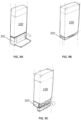
- FIGS. 2A and 2B a system including an aerosol generating device 100 and a module 201 is shown.
- the device 100 and module 201 may be as described above regarding FIGS. 1A-1D .
- FIGS. 2A and 2B show some additional detail regarding connection mechanisms that may be employed to operably couple the aerosol generating device 100 to the module 201.
- the aerosol generating device 100 includes a connector 120 accessible from the exterior of the housing 110 of the device 100.
- the connector 120 includes an electrical interconnect.
- the connector 120 may comprise a USB connector.
- the connector 120 may comprise a female USB connector.
- the module 201 includes a connector 220 accessible from the exterior of the housing 211 of the module 201.
- the connector 220 includes an electrical interconnect.
- the connector 220 may comprise a USB connector.
- the connector 220 may comprise a female USB connector, which may receive a male USB connector of another module (not shown) to allow connection of additional modules (for example, as shown in FIG. 1D ).
- the module 201 comprises a second connector 226 configured to connect with connector 120 of the aerosol generating device 100.
- the connector 226 may be a male USB connector.
- the first 220 and second 226 connectors of the module 201 are electrically coupled so that coupling of an additional module (not shown) to connector 220 will result in electrical coupling of the additional module with the aerosol generating device 100.
- FIGS. 3-9 illustrate various embodiments of modules 201 and aerosol generating devices 100 and associated connections.
- module 201 is a wireless charging module to allow wireless charging of a power supply of the aerosol generating device 100.
- Module 201 includes a USB connector 220 extending exterior to the housing 211 of the module 201.
- the device 100 includes a corresponding connector (not shown) which is accessible from the exterior of the housing 110 of the device and may be recessed within the housing 110.
- FIGS. 4A and 4B illustrate a device 100 having separate mechanical connectors 122 and electrical connector 124.
- the electrical connector 124 comprises a pin type connector configured to receive pins (not shown) extending from the housing 211 of the module 201.
- the mechanical connector 122 includes a snap type connector accessible from the exterior of the housing 110 of the device 100 and recessed in the housing 110.
- the mechanical connector 124 is configured to receive a corresponding connector (not shown) extending from the housing 211 of the module 201.
- FIGS. 5A-5C show an aerosol generating device 100 and a module 201 operably coupleable to the device 100.
- the module 201 includes a USB type connector 220 extending from the housing 211 of the module, and the device 100 includes a corresponding USB type connector 120 recessed in, but accessible external to, the housing 110 of the device 100.
- FIGS. 6A-6C show an aerosol generating device 100, a wrap connector 245, and a module 201 operably coupleable to the device 100 via the wrap connector 245.
- the wrap connector 245 may form a part of the module 201 as shown, may form a part of the device 100 (not shown), or may be separate from, but coupleable to, the module 201 and the device 100 (not shown).
- the device 100 and module 201 may be appropriately positioned relative to one another and the wrap connector 245 may be wrapped about one or both of the device 100 and module 201 to retain the device 100 and module 201 in the appropriate relative positions. Initial positioning may be facilitated by guides, magnetic connectors, or the like (not shown).
- the wrap 245 may comprise a connector, such as a magnetic strip 245 which may attach to the device 100 to secure the wrap to the device 100 and to retain the device 100 and the module 110 in place.
- the module 201 may be wirelessly connected to a power supply, controller, or power supply and controller of the device 100.
- FIG. 7 shows an embodiment where a wrap connector 240 that is part of module 201 includes a display 250.
- the wrap connector 240 may physically secure the aerosol generating device 100 relative to the module 201.
- Electrical connection between the module 201 and the device 100 may be wireless.
- a passive module 202 such as a container for consumables for use with the device 100, is also shown coupled to the device 100.
- FIG. 8 shows a module 201 comprising a speaker operably coupled to the aerosol generating device 100.
- FIGS. 9A-9C show multiple modules 201, 202, 203 operably coupled to an aerosol generating device 100.
- the modules 201, 202, 203 may be swapped and individually connected as shown.
- Module 201 comprises a container for housing consumables, such as heat sticks, for use with the aerosol generating device 100.
- Module 202 includes a secondary battery and a battery level indicator.
- Module 203 includes a charging case for earpods.
Claims (13)
- Système de génération d'aérosol comprenant :un dispositif de génération d'aérosol (100) comprenant un logement (110) ;un premier module (201) ;un deuxième module (202) ;un troisième module (203),dans lequel le premier module (201) peut être couplé fonctionnellement au dispositif de génération d'aérosol (100), au deuxième module (202) et au troisième module (203), etdans lequel le deuxième module (202) peut être couplé fonctionnellement au premier module (201), au troisième module (203), et au dispositif de génération d'aérosol (100),dans lequel le troisième module (203) peut être couplé fonctionnellement au dispositif de génération d'aérosol (100), au premier module (201), et au deuxième module (202), et dans lequel chacun du premier module (201), du deuxième module (202), et du troisième module (203) peut être couplé fonctionnellement au dispositif de génération d'aérosol (100) indirectement par l'intermédiaire d'un autre parmi le premier module (201), le deuxième module (202), ou le troisième module (203) lorsque l'autre parmi le premier module (201), le deuxième module (202), ou le troisième module (203) est directement couplé au dispositif de génération d'aérosol (100) à travers le logement (110).
- Système de génération d'aérosol selon la revendication 1, dans lequel le couplage fonctionnel du deuxième module (202) au premier module (201), tandis que le premier module (201) est couplé fonctionnellement au logement (110) du dispositif de génération d'aérosol (100), amène l'électronique du deuxième module (202) à se coupler électriquement à l'électronique du dispositif de génération d'aérosol (100).
- Système de génération d'aérosol selon la revendication 2, dans lequel le premier module (201) est passif.
- Système de génération d'aérosol selon l'une quelconque des revendications précédentes, dans lequel le logement (110) du dispositif de génération d'aérosol (100) comprend un premier raccordement pour coupler fonctionnellement le premier module (201) et comprend un deuxième raccordement pour se coupler fonctionnellement au deuxième module (202).
- Système de génération d'aérosol selon la revendication 4, dans lequel le deuxième module (202) peut être couplé fonctionnellement au premier raccordement du logement (110) du dispositif de génération d'aérosol (100), et dans lequel le premier module (201) peut être couplé fonctionnellement au deuxième raccordement du logement (110) du dispositif de génération d'aérosol (100).
- Système de génération d'aérosol selon l'une quelconque des revendications précédentes, dans lequel le premier module (201) comprend une première interconnexion électrique et une deuxième interconnexion électrique, et dans lequel le raccordement fonctionnel du premier module (201) avec le logement (110) du dispositif de génération d'aérosol (100) amène la première interconnexion électrique à se coupler électriquement avec l'électronique du dispositif de génération d'aérosol (100).
- Système de génération d'aérosol selon la revendication 6, dans lequel le deuxième module (202) comprend une première interconnexion électrique, dans lequel le raccordement fonctionnel du deuxième module (202) avec le premier module (201) amène la première interconnexion électrique du deuxième module (202) à se coupler électriquement avec la deuxième interconnexion électrique du premier module (201) de telle sorte que la première interconnexion électrique du deuxième module (202) est couplée électriquement à l'électronique du dispositif de génération d'aérosol (100) lorsque le premier module (201) est couplé fonctionnellement au logement (110) du dispositif de génération d'aérosol (100).
- Système de génération d'aérosol selon l'une quelconque des revendications précédentes, comprenant en outre un ou plusieurs modules supplémentaires, dans lequel chaque module supplémentaire peut être couplé fonctionnellement à un ou plusieurs parmi un autre module supplémentaire, le premier module (201), le deuxième module (202), et le logement (110) du dispositif de génération d'aérosol (100).
- Système de génération d'aérosol selon l'une quelconque des revendications précédentes, dans lequel le premier module (201) et le deuxième module (202) sont chacun choisis indépendamment dans le groupe constitué par un module comprenant une batterie auxiliaire, un module comprenant un appareil de communication sans fil, un module comprenant un chargeur sans fil, un module comprenant une interconnexion pour une charge câblée, un module comprenant un briquet électrique, un module comprenant un élément de sécurité électrique, un module comprenant un dispositif de chauffage, un module comprenant un boîtier de charge d'oreillettes sans fil, un module comprenant un ventilateur, un module comprenant un afficheur, un module comprenant un haut-parleur, un module comprenant une lampe de poche, un module comprenant une télécommande sans fil, un module comprenant un projecteur, un module comprenant une caméra, un module comprenant un appareil de rétroaction haptique, un module comprenant un capteur, un module comprenant un lecteur NFC, un module comprenant un processeur et une mémoire, un module comprenant un concentrateur USB, un module comprenant un appareil GPS, un module comprenant un récipient pour un ou plusieurs parmi un article de génération d'aérosol usagé, de l'argent en espèces, une carte de paiement, une carte professionnelle, des clés, un module comprenant une montre analogique, un module comprenant un câble de charge ou une clé de données, un module comprenant un décapsuleur, un module comprenant un stylo, un module comprenant un support d'écouteurs, et un module comprenant un anneau porte-clés.
- Système de génération d'aérosol selon l'une quelconque des revendications précédentes, dans lequel le dispositif de génération d'aérosol (100) est configuré pour générer un aérosol à partir d'un substrat pour une inhalation par un utilisateur.
- Système de génération d'aérosol selon la revendication 10, dans lequel le système comprend le substrat et le substrat comprend du tabac.
- Système de génération d'aérosol selon la revendication 10, dans lequel le système comprend le substrat et le substrat comprend de la nicotine.
- Système de génération d'aérosol selon l'une quelconque des revendications précédentes, dans lequel le dispositif de génération d'aérosol (100) comprend une source de puissance (190) .
Priority Applications (1)
| Application Number | Priority Date | Filing Date | Title |
|---|---|---|---|
| EP24161182.1A EP4353101A2 (fr) | 2019-10-16 | 2020-10-14 | Dispositif de génération d'aérosol à composants modulaires |
Applications Claiming Priority (2)
| Application Number | Priority Date | Filing Date | Title |
|---|---|---|---|
| EP19203687 | 2019-10-16 | ||
| PCT/IB2020/059656 WO2021074820A1 (fr) | 2019-10-16 | 2020-10-14 | Dispositif de génération d'aérosol à composants modulaires |
Related Child Applications (2)
| Application Number | Title | Priority Date | Filing Date |
|---|---|---|---|
| EP24161182.1A Division-Into EP4353101A2 (fr) | 2019-10-16 | 2020-10-14 | Dispositif de génération d'aérosol à composants modulaires |
| EP24161182.1A Division EP4353101A2 (fr) | 2019-10-16 | 2020-10-14 | Dispositif de génération d'aérosol à composants modulaires |
Publications (3)
| Publication Number | Publication Date |
|---|---|
| EP4044837A1 EP4044837A1 (fr) | 2022-08-24 |
| EP4044837B1 true EP4044837B1 (fr) | 2024-04-10 |
| EP4044837C0 EP4044837C0 (fr) | 2024-04-10 |
Family
ID=68281236
Family Applications (2)
| Application Number | Title | Priority Date | Filing Date |
|---|---|---|---|
| EP20793181.7A Active EP4044837B1 (fr) | 2019-10-16 | 2020-10-14 | Dispositif de génération d'aérosol comportant des composants modulaires |
| EP24161182.1A Pending EP4353101A2 (fr) | 2019-10-16 | 2020-10-14 | Dispositif de génération d'aérosol à composants modulaires |
Family Applications After (1)
| Application Number | Title | Priority Date | Filing Date |
|---|---|---|---|
| EP24161182.1A Pending EP4353101A2 (fr) | 2019-10-16 | 2020-10-14 | Dispositif de génération d'aérosol à composants modulaires |
Country Status (8)
| Country | Link |
|---|---|
| US (1) | US20230413900A1 (fr) |
| EP (2) | EP4044837B1 (fr) |
| JP (1) | JP2023501082A (fr) |
| KR (1) | KR20220081335A (fr) |
| CN (1) | CN114466601A (fr) |
| BR (1) | BR112022007262A2 (fr) |
| IL (1) | IL292122A (fr) |
| WO (1) | WO2021074820A1 (fr) |
Families Citing this family (1)
| Publication number | Priority date | Publication date | Assignee | Title |
|---|---|---|---|---|
| WO2024011591A1 (fr) * | 2022-07-15 | 2024-01-18 | Philip Morris Products S.A. | Appareil modulaire |
Family Cites Families (5)
| Publication number | Priority date | Publication date | Assignee | Title |
|---|---|---|---|---|
| KR20110006894U (ko) * | 2009-12-31 | 2011-07-07 | 최요석 | 금연보조 장치 |
| CN106793835A (zh) * | 2014-08-13 | 2017-05-31 | 菲利普莫里斯生产公司 | 包括多用途计算装置的气溶胶生成系统 |
| CN105077594A (zh) * | 2015-02-15 | 2015-11-25 | 卓尔悦(常州)电子科技有限公司 | 一种电子烟 |
| WO2018215142A1 (fr) * | 2017-05-23 | 2018-11-29 | Philip Morris Products S.A. | Dispositifs personnalisables pour plusieurs produits consommables |
| US20190173509A1 (en) * | 2017-12-01 | 2019-06-06 | David Thyane Martin | Electronic device case |
-
2020
- 2020-10-14 EP EP20793181.7A patent/EP4044837B1/fr active Active
- 2020-10-14 US US17/769,470 patent/US20230413900A1/en active Pending
- 2020-10-14 JP JP2022522071A patent/JP2023501082A/ja active Pending
- 2020-10-14 BR BR112022007262A patent/BR112022007262A2/pt unknown
- 2020-10-14 EP EP24161182.1A patent/EP4353101A2/fr active Pending
- 2020-10-14 WO PCT/IB2020/059656 patent/WO2021074820A1/fr active Application Filing
- 2020-10-14 CN CN202080066403.XA patent/CN114466601A/zh active Pending
- 2020-10-14 KR KR1020227011418A patent/KR20220081335A/ko unknown
-
2022
- 2022-04-10 IL IL292122A patent/IL292122A/en unknown
Also Published As
| Publication number | Publication date |
|---|---|
| US20230413900A1 (en) | 2023-12-28 |
| EP4044837A1 (fr) | 2022-08-24 |
| EP4353101A2 (fr) | 2024-04-17 |
| CN114466601A (zh) | 2022-05-10 |
| IL292122A (en) | 2022-06-01 |
| JP2023501082A (ja) | 2023-01-18 |
| WO2021074820A1 (fr) | 2021-04-22 |
| BR112022007262A2 (pt) | 2022-07-05 |
| EP4044837C0 (fr) | 2024-04-10 |
| KR20220081335A (ko) | 2022-06-15 |
Similar Documents
| Publication | Publication Date | Title |
|---|---|---|
| US20210236751A1 (en) | Radio-frequency identification (rfid) authentication system for aerosol delivery devices | |
| US20210177054A1 (en) | Electronic smoking device and capsule system | |
| CN107529826B (zh) | 荚体组件、分配主体和包括它们的电子烟装置 | |
| US10117462B2 (en) | Personal electronic vaporizer | |
| JP6903636B2 (ja) | モバイル装置用のケース | |
| EP4044837B1 (fr) | Dispositif de génération d'aérosol comportant des composants modulaires | |
| CN108631416A (zh) | 无线充电式电子烟盒及加热式非燃烧系统 | |
| WO2023239499A1 (fr) | Stérilisation interne de dispositifs de génération d'aérosol | |
| EP4186337B1 (fr) | Générateur d'aérosol doté d'un agencement de chauffage à batterie double | |
| US20240023606A1 (en) | Module for an aerosol provision device | |
| CN111373482B (zh) | 临床研究产品分配装置 | |
| EP3995009A1 (fr) | Dispositif de génération d'aérosol rechargeable | |
| WO2024057370A1 (fr) | Couvercle et dispositif de génération d'aérosol | |
| WO2024084608A1 (fr) | Dispositif de génération d'aérosol | |
| WO2023105614A1 (fr) | Appareil et procédé de traitement d'informations, et dispositif terminal | |
| WO2024004213A1 (fr) | Dispositif de génération d'aérosol et système de génération d'aérosol | |
| JPWO2021074820A5 (fr) |
Legal Events
| Date | Code | Title | Description |
|---|---|---|---|
| STAA | Information on the status of an ep patent application or granted ep patent |
Free format text: STATUS: UNKNOWN |
|
| STAA | Information on the status of an ep patent application or granted ep patent |
Free format text: STATUS: THE INTERNATIONAL PUBLICATION HAS BEEN MADE |
|
| PUAI | Public reference made under article 153(3) epc to a published international application that has entered the european phase |
Free format text: ORIGINAL CODE: 0009012 |
|
| STAA | Information on the status of an ep patent application or granted ep patent |
Free format text: STATUS: REQUEST FOR EXAMINATION WAS MADE |
|
| 17P | Request for examination filed |
Effective date: 20220324 |
|
| AK | Designated contracting states |
Kind code of ref document: A1 Designated state(s): AL AT BE BG CH CY CZ DE DK EE ES FI FR GB GR HR HU IE IS IT LI LT LU LV MC MK MT NL NO PL PT RO RS SE SI SK SM TR |
|
| DAV | Request for validation of the european patent (deleted) | ||
| DAX | Request for extension of the european patent (deleted) | ||
| GRAP | Despatch of communication of intention to grant a patent |
Free format text: ORIGINAL CODE: EPIDOSNIGR1 |
|
| STAA | Information on the status of an ep patent application or granted ep patent |
Free format text: STATUS: GRANT OF PATENT IS INTENDED |
|
| INTG | Intention to grant announced |
Effective date: 20230515 |
|
| GRAJ | Information related to disapproval of communication of intention to grant by the applicant or resumption of examination proceedings by the epo deleted |
Free format text: ORIGINAL CODE: EPIDOSDIGR1 |
|
| STAA | Information on the status of an ep patent application or granted ep patent |
Free format text: STATUS: REQUEST FOR EXAMINATION WAS MADE |
|
| INTC | Intention to grant announced (deleted) | ||
| GRAP | Despatch of communication of intention to grant a patent |
Free format text: ORIGINAL CODE: EPIDOSNIGR1 |
|
| STAA | Information on the status of an ep patent application or granted ep patent |
Free format text: STATUS: GRANT OF PATENT IS INTENDED |
|
| INTG | Intention to grant announced |
Effective date: 20231030 |
|
| GRAS | Grant fee paid |
Free format text: ORIGINAL CODE: EPIDOSNIGR3 |
|
| GRAA | (expected) grant |
Free format text: ORIGINAL CODE: 0009210 |
|
| STAA | Information on the status of an ep patent application or granted ep patent |
Free format text: STATUS: THE PATENT HAS BEEN GRANTED |
|
| AK | Designated contracting states |
Kind code of ref document: B1 Designated state(s): AL AT BE BG CH CY CZ DE DK EE ES FI FR GB GR HR HU IE IS IT LI LT LU LV MC MK MT NL NO PL PT RO RS SE SI SK SM TR |
|
| REG | Reference to a national code |
Ref country code: GB Ref legal event code: FG4D |
|
| REG | Reference to a national code |
Ref country code: CH Ref legal event code: EP |
|
| REG | Reference to a national code |
Ref country code: DE Ref legal event code: R096 Ref document number: 602020028862 Country of ref document: DE |