EP4044784B1 - Lagerschrank - Google Patents
Lagerschrank Download PDFInfo
- Publication number
- EP4044784B1 EP4044784B1 EP19948516.0A EP19948516A EP4044784B1 EP 4044784 B1 EP4044784 B1 EP 4044784B1 EP 19948516 A EP19948516 A EP 19948516A EP 4044784 B1 EP4044784 B1 EP 4044784B1
- Authority
- EP
- European Patent Office
- Prior art keywords
- section
- supply component
- delivery section
- production
- unit production
- Prior art date
- Legal status (The legal status is an assumption and is not a legal conclusion. Google has not performed a legal analysis and makes no representation as to the accuracy of the status listed.)
- Active
Links
Images


Classifications
-
- H—ELECTRICITY
- H05—ELECTRIC TECHNIQUES NOT OTHERWISE PROVIDED FOR
- H05K—PRINTED CIRCUITS; CASINGS OR CONSTRUCTIONAL DETAILS OF ELECTRIC APPARATUS; MANUFACTURE OF ASSEMBLAGES OF ELECTRICAL COMPONENTS
- H05K13/00—Apparatus or processes specially adapted for manufacturing or adjusting assemblages of electric components
- H05K13/08—Monitoring manufacture of assemblages
- H05K13/086—Supply management, e.g. supply of components or of substrates
-
- H—ELECTRICITY
- H05—ELECTRIC TECHNIQUES NOT OTHERWISE PROVIDED FOR
- H05K—PRINTED CIRCUITS; CASINGS OR CONSTRUCTIONAL DETAILS OF ELECTRIC APPARATUS; MANUFACTURE OF ASSEMBLAGES OF ELECTRICAL COMPONENTS
- H05K13/00—Apparatus or processes specially adapted for manufacturing or adjusting assemblages of electric components
- H05K13/02—Feeding of components
- H05K13/021—Loading or unloading of containers
Definitions
- the present description discloses a technology relating to a storage cabinet.
- a storage cabinet described in Patent Literature 1 stores a mounting head and a feeder device.
- the exchange supporting apparatus determines a mounting head and a feeder device which are to be mounted on a component mounter from mounting heads and feeder devices which are stored in the storage cabinet based on production job information and maintenance information.
- the exchange supporting apparatus searches for a feeder device which holds a reel accommodating a type of components needed for a production after the setup change. Further, a guide section of the exchange supporting apparatus informs an operator of a mounting head and a feeder device which are to be delivered from the storage cabinet.
- a setting control section sets a suction nozzle required by a component mounter on a nozzle tray based on information received from at least one of the component mounter and a management device.
- WO 2019 138548 A1 discloses a storage device that comprises an acquisition unit and a management unit.
- the acquisition unit uses a radio device provided at the entrance of the storage facility and effects radio communication with a first wireless tag attached to the case and a second wireless tag attached to each of the multiple housable items.
- the acquisition unit then acquires identification information retained in the first wireless tag for identifying the casing and discrimination information retained in the second wireless tag for discriminating among the multiple housable items.
- the management unit associates the identification information and the discrimination information acquired by the acquisition unit and manages the association therebetween.
- both a supply component such as an article or the like which is mounted on a board by the board work machine and a device which is detachably provided on the board work machine for use in board work are necessary.
- a supply component and a device which match a type of board products to be produced become necessary.
- combinations of a supply component and a device for delivery are limited.
- a storage cabinet which can store a supply component and a device separately and which can deliver a supply component and a device for use for a unit production which specifies a production of an identical type of board products in an associated fashion.
- the present description discloses a storage cabinet including a first storage section, a second storage section, a delivery section, and a moving section.
- the first storage section stores a supply component which is at least one of an article which is provided on a board by a board work machine configured to perform predetermined board work on the board and the board before the article is provided thereon.
- the second storage section stores a device which is detachably provided on the board work machine for use in the board work.
- the delivery section delivers the supply component and the device in an associated fashion which are used for a predetermined unit production included in a production plan which prescribes an order of unit productions which each specify a production of an identical type of board products using the board work machine.
- the moving section moves the supply component stored in the first storage section to the delivery section and moves the device stored in the second storage section to the delivery section. The device and the supply component are accommodated together in an accommodation case.
- the storage cabinet includes the first storage section, the second storage section, the delivery section, and the moving section.
- the storage cabinet can store the supply component in the first storage section and the device in the second storage section.
- the moving section moves the supply component stored in the first storage section to the delivery section and moves the device stored in the second storage section to the delivery section, whereby the delivery section can deliver the supply component and the device in the associated fashion for use in the predetermined unit production.
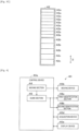
- Board production facility 80 includes board working line 10L, arrival section 20, conveyance vehicle 30, and storage cabinet 40.
- board working line 10L predetermined board work is performed on board 90.
- the type and number of board work machines 10 constituting board working line 10L are not limited.
- board working line 10L of the present embodiment includes multiple (five) board work machines 10 such as printer 10a, printing inspection machine 10b, component mounter 10c, reflow furnace 10d, and appearance inspection machine 10e, and board 90 is conveyed sequentially in this order by a board conveyance device.
- Printer 10a prints solder in multiple component mounting positions on board 90.
- Solder that is printed on board 90 has a predetermined viscosity, and the solder so printed functions as a bonding material for bonding board 90 and a component that is mounted on board 90 together.
- solder is accommodated in solder accommodation container 91c.
- solder accommodation container 91c For example, a bottomed cylindrical or tubular sealable container can be used as solder accommodation container 91c.
- Printing inspection machine 10b inspects a print state of solder which is printed by printer 10a.
- Component mounter 10c mounts multiple components on board 90 on which solder is printed.
- Component mounter 10c may be provided one, or multiple component mounters 10c may be provided. In the case that multiple component mounters 10c are provided, those multiple component mounters 10c can share a mounting operation for mounting multiple components on board 90.
- Component mounter 10c includes a component supply device for supplying components which are mounted on board 90.
- the component supply device can supply components using, for example, feeder 95b including reel 91a, tray 91b, and the like which are shown in Fig. 2 .
- a component tape (a carrier tape) which accommodates components thereon is wound around reel 91a.
- Reel 91a is rotatably and detachably provided in feeder 95b, and a distal end portion of the component tape is drawn out to a component take-out or pickup section provided in feeder 95b, whereby components are sequentially supplied.
- Reel 91a can supply, for example, a relatively small component such as a chip component.
- Tray 91b can supply a relatively large component such as, for example, a Quad Flat Package (QFP), a Ball Grid Array (BGA), and the like.
- the component supply device can also supply, for example, components accommodated in parts accommodating container 91d. Multiple components are accommodated in parts accommodating container 91d without being arranged.
- mounting head 95a is detachably (in an exchangeable fashion) provided on component mounter 10c.
- At least one holding member 95c is provided detachably (in an exchangeable fashion) provided on mounting head 95a.
- a suction nozzle, a chuck, or the like can be used as holding member 95c.
- Component mounter 10c picks up and holds a component supplied by the component supply device and mounts the component on board 90, which is positioned, by use of mounting head 95a and holding member 95c.
- Holding member 95c can be changed as required in accordance with the type of a component to be mounted in a mounting process of mounting a component on board 90. For example, in the case that holding member 95c for use for a mounting process to be executed is not attached to mounting head 95a of component mounter 10c, holding member 95c accommodated in holding member accommodating device 95d can be attached to mounting head 95a.
- Holding member accommodating device 95d is capable of accommodating multiple holding members 95c in a detachable (exchangeable) fashion and is installed in a predetermined position inside component mounter 10c in a detachable (exchangeable) fashion.
- Reflow furnace 10d heats board 90 on which multiple components are mounted by component mounter 10c to melt the solder printed thereon for soldering.
- Appearance inspection machine 10e inspects the mounting state or the like of the multiple components mounted on board 90 by component mounter 10c.
- board 90 is conveyed sequentially so that the production processes including the inspection process can be executed thereon for production of board product 900 by use of multiple (five) board work machines 10s.
- Board working line 10L can also include, as required, board work machines 10 such as, for example, a function inspection machine, a buffer device, a board supply device, a board flipping device, a shield mounting device, an adhesive application device, an ultraviolet ray irradiation device, and the like.
- Multiple (five) board work machines 10 and management device 19, which make up board working line 10L, are provided so as to be capable of communicating with each other by a wired or wireless communication section.
- Management device 19 controls multiple (five) board work machines 10, which make up board working line 10L, to monitor operation situations of board working line 10L.
- Management device 19 stores various control data for controlling multiple (five) board work machines 10.
- Management device 19 transmits the control data to each of multiple (five) board work machines 10.
- each of multiple (five) board work machines 10 transmits an operation situation and a production situation to management device 19.
- At least one of article 91 which is provided on board 90 by board work machine 10, which is configured to perform predetermined board work on board 90, and board 90 on which any article 91 has not yet been mounted will be referred to as supply component 9S.
- device 9F a thing which is detachably provided on board work machine 10 for use for board work.
- board working line 10L includes printer 10a.
- solder accommodated in solder accommodation container 91c corresponds to article 91.
- the squeegee and the mask correspond to device 9F.
- the printing head and a dispense head correspond to device 9F.
- board working line 10L includes component mounter 10c.
- a component accommodated in a component tape wound around reel 91a corresponds to article 91.
- a component accommodated on tray 91b corresponds to article 91.
- a component accommodated in parts accommodating container 91d corresponds to article 91.
- Mounting head 95a which is detachably provided on component mounter 10c corresponds to device 9F.
- Feeder 95b which is detachably provided in component mounter 10c corresponds to device 9F.
- Holding member 95c which is detachably provided on component mounter 10c via mounting head 95a corresponds to device 9F.
- Holding member accommodating device 95d which is detachably provided in component mounter 10c corresponds to device 9F.
- board working line 10L includes printing inspection machine 10b.
- board working line 10L includes appearance inspection machine 10e.
- an inspection head for inspecting an inspection target object corresponds to device 9F.
- Board 90 on which any article 91 has not yet been mounted is conveyed to printer 10a shown in Fig. 1 . That board 90 is included in supply component 9S.
- supply component 9S arrives at arrival section 20, predetermined landing work is performed. Then, supply component 9S is accommodated in accommodation case 93, and this accommodation case 93 is mounted on conveyance vehicle 30 and is conveyed to storage cabinet 40. Once supply component 9S is stored in storage cabinet 40, supply component 9S is then supplied to board working line 10L as required.
- identification code 92 is provided on supply component 9S.
- Identification code 92 stores identification information for identifying supply component 9S.
- a one-dimensional code, a two-dimensional code, a wireless tag, or the like can be used for identification code 92.
- the management device When supply component 9S arrives at arrival section 20, an operator at arrival section 20 issues identification information using, for example, the management device.
- the operator reads a barcode or the like which is provided on supply component 9S by a supplier (a vendor) using a barcode reader or the like. Then, the operator can also obtain supply component information for supply component 9S from a database in which the supply information for supply component 9S is registered.
- the operator stores at least the identification information of the identification information and the supply component information in identification code 92 using the management device.
- the operator at arrival section 20 attaches identification code 92 which stores at least the identification information therein to supply component 9S and accommodates that supply component 9S in accommodation case 93.
- Accommodation case 93 need only accommodate at least one supply component 9S and hence can take various forms.
- Specific code 94 is provided on accommodation case 93.
- Specific code 94 stores specific information for specifying accommodation case 93. For example, a one-dimensional code, a two-dimensional code, a wireless tag, or the like can be used for specific code 94.
- Fig. 2 is a plan view showing an example of an accommodation state in which supply component 9S and device 9F are accommodated in accommodation case 93.
- Fig. 2 shows an example of a state in which reel 91a around which a component tape accommodating a component corresponding to article 91 is wound is accommodated in accommodation case 93.
- Fig. 2 shows an example of a state in which trays 91b each accommodating a component corresponding to article 91 are accommodated (loaded) in accommodation case 93.
- Tray 91b is accommodated in a packaging bag, and identification code 92 is attached to the packaging bag of tray 91b.
- FIG. 2 shows an example of a state in which solder accommodation containers 91c each accommodating solder corresponding to article 91 are accommodated in accommodation case 93.
- Fig. 2 shows an example of a state in which substrate 90 on which any article 91 has not yet been provided is accommodated d in accommodation case 93.
- FIG. 2 shows an example of a state in which mounting head 95a, feeder 95b, holding member 95c, and holding member accommodating device 95d, which each correspond to device 9F, are accommodated individually in corresponding accommodation cases 93.
- Mounting head 95a and feeder 95b are individually accommodated in corresponding accommodation cases 93.
- Holding member 95c can be accommodated in an accommodation space which accommodates detachably holding member 95c and can also be accommodated detachably in holding member accommodating device 95d.
- Accommodation case 93 can also accommodate supply component 9S and device 9F together.
- parts accommodating containers 91d, each accommodating a component corresponding to article 91, and holding member accommodating device 95d and holding members 95c, each corresponding to device 9F are accommodated together in accommodation case 93 shown in Fig. 2 .
- a shock absorbing member is provided in accommodation case 93, whereby vibration or the like which would be applied to supply components 9S and device 9F during conveyance or the like is reduced.
- the operator at arrival section 20 mounts accommodation case 93 which accommodates therein at least one of supply component 9S and device 9F on conveyance vehicle 30.
- the operator can pull conveyance vehicle 30.
- a self-propelled unmanned conveyance vehicle (an automated guided vehicle (AGV) ), which does not have to be pulled by the operator, can also be used for conveyance vehicle 30.
- conveyance vehicle 30 adopts an unmanned conveyance vehicle.
- Board working line 10L, arrival section 20, conveyance vehicle 30, and storage cabinet 40 are provided so as to be capable of communicating with each other by a wired or wireless communication section.
- management device 19 transmits a conveyance command to conveyance vehicle 30.
- the conveyance command includes a conveyance destination of that accommodation case 93.
- Management device 19 selects storage cabinet 40 which can store that accommodation case 93 and determines a conveyance destination.
- conveyance vehicle 30 conveys that accommodation case 93 to storage cabinet 40 which is designated as the conveyance destination.
- Conveyance vehicle 30 can also convey at least one of supply component 9S and device 9F without using accommodation case 93.
- the operator can convey at least one of supply component 9S and device 9F without using conveyance vehicle 30.
- at least a part of the work described as being performed by the operator can be automated using a conveyance device (for example, a belt conveyor), an actuator (for example, a robot arm and the like.), the management device, or the like.
- supply component 9S and device 9F that have arrived at arrival section 20 is conveyed to storage cabinet 40.
- at least one of supply component 9S and device 9F which become unnecessary in board working line 10L is conveyed to storage cabinet 40.
- Supply component 9S and device 9F which are conveyed to storage cabinet 40 are stored in storage cabinet 40 and are then conveyed to board working line 10L as required.
- Storage cabinet 40 need only store supply component 9S and device 9F, and hence, storage cabinet 40 can take various forms.
- storage cabinet 40 of the present embodiment is formed in, for example, an octagonal prism shape.
- storage cabinet 40 includes first opening section 41a, second opening section 41b, storage section 42, delivery section 43, control device 40a, and moving device 40b.
- Storage section 42 includes first storage section 42a and second storage section 42b and can further include third storage section 42c.
- Delivery section 43 includes first delivery section 43a and second delivery section 43b. Delivery portion 43 can be formed into, for example, wheeled table 46 or rack 47.
- control device 40a when taken as a control block, includes moving section 44.
- Control device 40a can further include guide section 45.
- storage cabinet 40 can include at least one of work space 40c, acquisition device 40d, display device 40e, and delivery space 40f.
- work space 40c acquisition device 40d
- display device 40e display device 40e
- delivery space 40f delivery space 40f.
- storage cabinet 40 includes all the parts and devices described above. Delivery section 43 is formed into rack 47.
- first opening section 41a is provided in a front surface of storage cabinet 40
- second section 41b is provided in a side surface of storage cabinet 40.
- Supply component 9S and device 9F are received in and delivered out from first opening section 41a.
- First opening section 41a is formed larger than supply component 9S and device 9F so that supply component 9S and device 9F can be received in and delivered out from first opening section 41a.
- At least one of supply component 9S and device 9F can be received in and delivered out via first opening section 41a while being accommodated in accommodation case 93.
- first opening section 41a is formed larger than accommodation case 93 so that accommodation case 93 can be received in and delivered out from first opening section 41a.
- Supply component 9S and device 9F are delivered out from second opening section 41b. What is described above about first opening section 41a will be true with second opening section 41b.
- acquisition device 40d is provided in first opening section 41a.
- Acquisition device 40d reads identification code 92 provided on supply component 9S and acquires the identification information for identifying supply component 9S .
- acquisition device 40d reads identification code 92 provided on device 9F and acquires the identification information for identifying device 9F.
- a known reader for example, a code reader for reading a one-dimensional code and a two-dimensional code, a wireless reader for performing wireless communication with a wireless tag, or the like
- a known reader for example, a code reader for reading a one-dimensional code and a two-dimensional code, a wireless reader for performing wireless communication with a wireless tag, or the like
- acquisition device 40d is set above work space 40c provided in the vicinity of first opening section 41a.
- Acquisition device 40d reads identification code 92 provided on supply component 9S to acquire at least the identification information of the identification information and the supply component information when supply component 9S is received in via first opening section 41a.
- acquisition device 40d reads identification code 92 provided on device 9F to acquire at least the identification information of the identification information and the device information on device 9F when device 9F is received in via first opening section 41a.
- Acquisition device 40d can read specific code 94 provided on accommodation case 93 to acquire the specific information when accommodation case 93 is received in via first opening section 41a. In this case, acquisition device 40d can acquire the identification information of at least one of supply component 9S and device 9F which is accommodated in accommodation case 93 based on the correspondence between the specific information and the identification information.
- first opening section 41a functions both as the receiving section and the delivery section through which supply component 9S and device 9F can be received in or delivered out
- second opening section 41b functions exclusively as the delivery section through supply component 9S and device 9F can be delivered out.
- Storage section 42 need only store both supply component 9S and device 9F and hence can take various forms. As shown in Fig. 3b , storage section 42 of the present embodiment is disposed in a circular shape when viewed in a vertical direction (a Z-axis direction). As shown in Fig. 3c , storage section 42 includes first storage sections 42a each configured to store supply component 9S and second storage sections 42b each configured to store device 9F.
- first storage sections 42a and second storage sections 42b are changed as required.
- at least one storage section 42 of multiple storage sections 42 can include only first storage section 42a, while at least one storage section 42 of the other storage sections 42 of multiple storage sections 42 can include only second storage section 42b.
- a part of first storage sections 42a or second storage sections 42b is eliminated so as to secure work space 40c and delivery space 40f.
- first storage section 42a can be set so as to match supply component 9S to be stored therein
- shape and size (width, depth, and height) of second storage section 42b can be set so as to match device 9F to be stored therein
- storage section 42 can also store accommodation case 93 which accommodates at least one of supply component 9S and device 9F therein.
- first storage section 42a and second storage section 42b can be set so as to match accommodation case 93.
- shape and size (width, depth, and height) of accommodation case 93 can be set so as to match the shapes and sizes of first storage section 42a and second storage section 42b.
- storage section 42 can also include third storage sections 42c which each store both supply component 9s and device 9F.
- Accommodation case 93 which accommodates both supply component 9S and device 9F (in which device 9F and supply component 9S are accommodated together) is stored in third storage section 42c.
- supply component 9S, device 9F, and accommodation case 93 can also be stored in suitable storage sections 42.
- storage section 42 where supply component 9S is stored is first storage section 42a.
- Storage section 42 where device 9F is stored is second storage section 42b.
- Storage section 42 where both supply component 9S and device 9F are stored is third storage section 42c.
- supply component 9S, device 9F, and accommodation case 93 may be stored in any storage cabinets 40, as long as those storage cabinets 40 include suitable storage sections 42.
- a production plan prescribes an order of unit productions UJO which each specify a production of an identical type of board products 900 using board work machines 10.
- the production plan prescribes a production of multiple types (for example, three types) of board products 900 as in a production order of a production of a first type of board products 900, a production of a second type of board products 900, a production of a third type of board products 900, and the like.
- the production plan can also include a production number of board product 900 to be produced, a production period, a delivery time, supply component 9S and device 9F which are to be used, and the like.
- the production plan can also include board working line or lines 10L for use for production.
- the production plan may be a production plan for one type of board products 900.
- Delivery section 43 delivers out supply component 9S and device 9F in associated fashion which are to be used for a predetermined unit production UJ0 included in the production plan.
- delivery section 43 includes first delivery section 43a and second delivery section 43b.
- Supply component 9S for use for unit production UJ0 is delivered to first delivery section 43a.
- Device 9F for use for unit production UJ0 which uses supply component 9S delivered out from first storage section 43a is delivered to second delivery section 43b.
- First delivery section 43a and second delivery section 43b can be formed into, for example, wheeled table 46 or rack 47 which can hold supply component 9S and device 9F. Wheeled table 46 or rack 47 need only hold supply component 9S and device 9F, and hence, wheeled table 46 and rack 47 can take various forms. As shown in Fig. 3a , in the present embodiment, first delivery section 43a and second delivery section 43b are formed into rack 47 which includes multiple storage spaces.
- first storage section 43a is formed in an upper space of rack 47
- second delivery section 43b is formed in a lower space of rack 47
- a door portion is provided in second opening section 41b shown in Fig. 3b .
- the upper space and the lower space of rack 47 can communicate with delivery space 40f via second opening section 41b.
- the door portion is caused to be in an open state by control device 40a when supply component 9S and device 9F are delivered out.
- supply component 9S and device 9F which are used for identical unit production UJ0 are delivered out in an associated fashion by way of second opening section 41b.
- supply component 9S and device 9F are so delivered out, the door portion is caused to be in a closed state by control device 40a.
- Control device 40a includes a known arithmetic unit and a storage device, as well as a control circuit which is configured therein. Control device 40a is provided so as to be capable of communicating with moving device 40b, acquisition device 40d, and display device 40e and can control these devices. In addition, control device 40a can also cause a door portion provided in first opening section 41a and the door portion provided in second opening section 41b to be opened and closed. Further, control device 40a can store supply information on supply component 9S and can also notify management device 19 of the supply component information.
- the supply information can include a type of a component accommodated in reel 91a, the number of components (the number of remaining components), a reel diameter, a reel model type, and a reel supplier (vendor), an expiration date, and the like.
- control device 40a can store device information on device 9F and can also notify management device 19 of the device information.
- the device information can include the number of times of use of mounting head 95a, the duration of use of mounting head 95a, component mounter 10c which uses mounting head 95a, the maintenance time of mounting head 95a, and the like.
- moving device 40b moves supply component 9S so received to predetermined first storage section 42a, and when supply component 9S is delivered out, moving device 40b moves supply component 9S stored in first storage section 42a to delivery space 40f.
- moving device 40b moves device 9F so received to predetermined second storage section 42b, and when device 9F is delivered out, moving device 40b moves device 9F stored in second storage section 42b to delivery space 40f.
- accommodation case 93 which accommodates at least one of supply component 9S and device 9F is received in storage cabinet 40 by way of first opening section 41a. That is, when accommodation case 93 is received in by way of first opening section 41a, moving device 40b moves accommodation case 93 so received to predetermined first storage section 42a, second storage section 42b or third storage section 42c. In addition, when accommodation case 93 is delivered out, moving device 40b moves accommodation case 93 stored in first storage section 42a, second storage section 42b or third storage section 42c to delivery space 40f.
- moving device 40b of the present embodiment is provided radially inwards of storage section 42 as viewed in the vertical direction (the Z-axis direction).
- Moving device 40b need only be able to move a target object (supply component 9S and device 9F or accommodation case 93) and hence can take various forms.
- a robot arm an articulated robot
- a lifting and lowering slide mechanism and the like can be used for moving device 40b.
- Moving device 40b can include, for example, a raising/lowering section 40b1 and gripping section 40b2. Raising/lowering section 40b1 can rotate around an axis extending along the vertical direction (the Z-axis direction) and can raise or lower gripping section 40b2 along the vertical direction (the Z-axis direction). Gripping section 40b2 can advance or retreat and can hold or release a hold of a target object. As a result, moving device 40b can store a target object that is received in by way of first opening section 41a in storage section 42 and can move the target object to delivery space 40f. In addition, moving device 40b can also move the target object moved to delivery space 40f to delivery section 43. Further, moving device 40b can include a conveyance device (that is, a belt conveyor or the like) in delivery space 40f. In this case, the conveyance device can move the target object moved to delivery space 40f to delivery section 43.
- a conveyance device that is, a belt conveyor or the like
- moving device 40b When delivering supply component 9s, moving device 40b can also move supply component 9S stored in first storage section 42a to work space 40c provided in first opening section 41a. Similarly, when delivering device 9F, moving device 40b can move device 9F stored in second storage section 42b to work space 40c provided in first opening section 41a. In addition, when delivering both supply component 9S and device 9F, moving device 40b can move supply component 9S and device 9F which are stored in third storage section 42c to work space 40c provided in first opening section 41a. What is described above applies to a case in which at least one of supply component 9S and device 9F is accommodated in accommodation case 93.
- At least one of supply component 9S and device 9F is stored while being accommodated in accommodation case 93 and is delivered out while being accommodated in accommodation case 93.
- at least one of supply component 9S and device 9F which is accommodated in accommodation case 93 can easily be moved, and hence, irrespective of types of supply component 9S and device 9F, gripping section 40b2 of moving device 40b can easily be shared with.
- at least one of supply component 9S and device 9F can easily be managed to thereby reduce a risk of being lost or the like by storing and delivering at least one of supply component 9S and device 9F while being accommodated in accommodation case 93.
- accommodation case 93 can accommodate various types of supply components 9S and can accommodate various types of devices 9F.
- accommodation case 93 accommodates both supply component 9S and device 9F (can accommodate device 9F and supply component 9S together).
- board work machine 10 is component mount 10c for mounting a component, which is supply component 9S, on board 90, which is supply component 9S.
- holding member 95c for holding a component is limited depending on a type of component, there may be a case in which a component and holding member 95c for holding the component are preferably managed together.
- holding member 95c which is device 9F for picking up to hold a component and mounting the component on board 90, and a component which can be held by holding member 95c need only be accommodated together in accommodation case 93.
- device 9F and supply component 9S need only be accommodated together in accommodation case 93 as the degree at which supply component 9S and device 9F are related to each other (the degree of association) becomes higher.
- storage cabinet 40 includes display device 40e.
- a know display device can be used for display device 40e, and this display device 40e displays various types of data in such a way that the operator can visually recognize them.
- Display device 40e displays, for example, supply component information on supply component 9S stored in first storage section 42a, device information on device 9F stored in second storage section 42b, and the like in response to an operation by the operator.
- control device 40a can store positional information, receiving and delivery information and storage information on supply component 9S and device 9F in storage section 42, and display device 40e can also display these pieces of information.
- the positional information indicates storage locations of supply component 9S and device 9F.
- the receiving and delivery information indicates receiving date and time and delivery date and time of each of supply component 9S and device 9F.
- the storage information includes, for example, information on the ambient temperature in storage section 42, the humidity in storage section 42, and the like.
- Control device 40a stores positional information and receiving date and time of each of supply component 9S and device 9F when that supply component 9S and that device 9F are received to be stored.
- Control device 40a stores storage information on supply component 9S and device 9F while that supply component 9S and that device 9F are being stored.
- Control device 40a stores delivery date and time of each of supply component 9S and device 9F when that supply component 9S and that device 9F are delivered out.
- Display device 40e of the present embodiment is made up of a touch panel, and display device 40e also functions as an input device for receiving various types of operations by the operator.
- the operator can also specify supply component 9S and device 9F which are desired to be delivered out from storage cabinet 40 by use of the touch panel (display device 40e functioning as the input device).
- storage cabinet 40 delivers out supply component 9S and device 9F which are so specified.
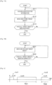
- control device 40a when taken as control blocks, control device 40a includes moving section 44 and guide section 45. Control device 40a executes control programs in accordance with flowcharts shown in Figs. 5a and 5b .
- Fig. 5a shows an example of a control procedure for a receiving operation of supply component 9S and device 9F.
- Control device 40a acquires identification information of supply component 9S using acquisition device 40d when supply component 9S is received in via first opening section 41a (Step S11). Similarly, control device 40a can also acquire identification information of device 9F using acquisition device 40d when device 9F is received in via first opening section 41a.
- control device 40a can also acquire specific information of accommodation case 93 using acquisition device 40d when accommodation case 93 is received in via first opening section 41a. In this case, control device 40a acquires the identification information of at least one of supply component 9S and device 9F which is accommodated in accommodation case 93 based on the correspondence between the specific information and the identification information. In any of the cases, control device 40a causes the storage device to store the acquired identification information.
- moving section 44 causes moving device 40b to move supply component 9S to predetermined first storage section 42a for storage therein (Step S12). Similarly, moving section 44 can also cause moving device 40b to move device 9F to predetermined second storage section 42b for storage therein. In addition, moving section 44 can also cause moving device 40b to move supply component 9S and device 9F to predetermined third storage section 42c for storage therein. Further, moving section 44 can also cause moving device 40b to move accommodation case 93 to predetermined storage section 42 for storage therein. In any of the cases, control device 40a causes the storage device to store the positional information and the receiving dates and times of supply component 9S and device 9F.
- control device 40a determines whether all supply components 9S and devices 9F that are scheduled to be received in storage cabinet 40 have been so received (step S13). If all supply components 9S and devices 9F that are scheduled to be received in storage cabinet 40 have been so received (if Yes in Step S13), control device 40a ends temporarily the control for the receiving operation. If all supply components 9S and devices 9F that are scheduled to be received in storage cabinet 40 have not yet been so received (if NO in Step S13), control device 40a returns to the operation in Step S 11 for the receiving operation. Then, control device 40a repeats the operations shown in Steps S11 to S13 until all supply components 9S and devices 9F that are scheduled to be received in storage cabinet 40 have been so received.
- Fig. 5b shows an example of a control procedure for a delivery operation of supply component 9S and device 9F.
- the production plan is managed by, for example, management device 19, and management device 19 transmits a delivery command of delivering supply component 9S and device 9F which are to be used for identical unit production UJ0 to storage cabinet 40 based on the production plan.
- storage cabinet 40 associates supply component 9S and device 9F with each other for use for specified identical unit production UJ0 and then delivers that supply component 9S and that device 9F which are so associated with each other.
- moving section 44 moves supply component 9S stored in first storage section 42 to delivery section 43 and moves device 9F stored in second storage section 42b to delivery section 43.
- moving section 44 can also move supply component 9S stored in first storage section 42a to first delivery section 43a and move device 9F stored in second storage section 42b to second delivery section 43b.
- moving section 44 causes moving device 40b to move supply component 9S stored in first storage section 42a to delivery space 40f and then to move that supply component 9S moved to delivery space 40f to first delivery section 43a.
- moving section 44 causes moving device 40b to move device 9F stored in second storage section 42b to delivery space 40f and then to move that device 9F moved to delivery space 40f to second delivery section 43b (step S21).
- Moving section 44 can also cause moving device 40b to move accommodation case 93 stored in storage section 42 to delivery space 40f and then to move that accommodation case 93 moved to delivery space 40f to delivery section 43.
- control device 40a causes the storage device to store the delivery dates and times of supply component 9S and device 9F.
- control device 40a determines whether all supply components 9S and devices 9F that are scheduled to be delivered out from storage cabinet 40 have been so delivered out (Step S22). If control device 40a determines that all supply components 9S and devices 9F that are scheduled to be delivered out from storage cabinet 40 have been so delivered out (Yes in Step S22), control device 40a ends temporarily the control for delivery operation. If control device 40a determines that all supply components 9S and devices 9F that are scheduled to be delivered out from storage cabinet 40 have not yet been so delivered out (No in Step S22), control device 40a returns to the operation in Step S21. Then, control device 40a repeats the operations shown in Steps S21 and S22 until all supply components 9S and devices 9F that are scheduled to be delivered out from storage cabinet 40 have been so delivered out.
- first unit production UJ1 one unit production UJ0 in which board products 900 are produced by board work machine 10 is referred to as first unit production UJ1.
- second unit production UJ2 at least one unit production UJ0 which is carried out after first unit production UJ1 on is referred to as second unit production UJ2.
- first unit production UJ1 since board products 900 are produced by board work machine 10, device 9F has already been mounted in board work machine 10. Therefore, there are fewer delivery requests for device 9F in first unit production UJ1 than in second unit production UJ2.
- moving section 44 can move supply component 9S and device 9F which are used for second unit production UJ2. Specifically speaking, moving section 44 causes moving device 40b to move supply component 9S and device 9F which are used for second production UJ2 based on a delivery command received from management device 19.
- Storage cabinet 40 of the present embodiment includes guide section 45.
- Guide section 45 notifies the operator of first delivery section 43a from which supply component 9S for use for second unit production UJ2 is delivered out and second delivery section 43b from which device 9F for use for second unit production UJ2 is delivered out. As a result, the operator can easily recognize supply component 9S and device 9F which are used for second unit production UJ2.
- Guide section 45 need only notify the operator of first delivery section 43a and second delivery section 43b, and hence, guide section 45 can take various forms.
- guide section 45 can display the positions of those first delivery section 43a and second delivery section 43b which are formed into rack 47 by use of display device 40e shown in Fig. 3a .
- guide section 45 can also display the positions of those first delivery section 43a and second delivery section 43b which are formed into rack 47 by use of a display device which is provided on rack 47.
- guide section 45 displays an indicator in the vicinity of the upper space of rack 47 indicating that the upper space is a delivery location for supply component 9S, whereby guide section 45 notifies that that first delivery section 43a is formed in the upper space of rack 47.
- guide section 45 displays an indicator in the vicinity of the lower space of rack 47 indicating that the lower space is a delivery location for device 9F, whereby guide section 45 notifies that that second delivery section 43b is formed in the lower space of rack 47.
- first unit production UJ1 since board products 900 are produced by board work machine 10, there is a possibility of, for example, occurrence of a shortage of components accommodated in reel 91a (a shortage of supply components 9S).
- management device 19 transmits a delivery command of delivering supply components 9S required to storage cabinet 40.
- storage cabinet 40 delivers out supply components 9S so required.
- moving section 44 causes moving device 40b to move supply component 9S which is used for first unit production UJ1 to first delivery section 43a.
- moving section 44 causes moving device 40b to move supply component 9S which is used for first unit production UJ1 to first delivery section 43a based on a delivery command received from management device 19.
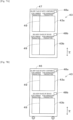
- guide section 45 need only notify of first delivery section 43a from which supply component 9S which is used for first unit production UJ1 is delivered out and first delivery section 43a from which supply component 9S which is used for second unit production UJ2 is delivered out in a distinguishable fashion.
- guide section 45 can notify through display that a part of the upper space of rack 47 shown in Fig. 7a is allocated for the current production to thereby notify the operator that supply component S9 which is used for first unit production UJ1 is delivered to the space so allocated.
- guide section 45 can notify through display that the remainder of the upper space of rack 47 shown in Fig. 7a is allocated for a subsequent production to thereby notify the operator that supply component 9S which is used for second unit production UJ2 is delivered to the space so allocated.
- the operator can identify to distinguish first delivery section 43a from which supply component 9S which is used for first unit production UJ1 is delivered out from first delivery section 43a from which supply component 9S which is used for second unit production UJ2 is delivered out.
- moving section 44 can also causes moving device 40b to move device 9F which is used for first unit production UJ1 to second delivery section 43b.
- guide section 45 need only notify the operator of second delivery section 43b from which device 9F which is used for first unit production UJ1 is delivered out and second delivery section 43b from which device 9F which is used for second unit production UJ2 is delivered out in a distinguishable fashion.
- guide section 45 can notify through display that a portion of the lower space of rack 47 shown in Fig. 7a is allocated for the current production to thereby notify the operator that device 9F which is used for first unit production UJ1 is delivered to the space so allocated.
- guide section 45 can notify through display that the remainder of the lower space of rack 47 shown in Fig. 7a is allocated for a subsequent production to thereby notify the operator that device 9F which is used for second unit production UJ2 is delivered to the space so allocated.
- the operator can identify to distinguish second delivery section 43b from which device 9F which is used for first unit production UJ1 is delivered out from second delivery section 43b from which device 9F which is used for second unit production UJ2 is delivered out.
- partition plate 49 can be provided in rack 47.
- Partition plate 49 provided in first delivery section 43a shown in Fig. 7a divides first delivery section 43a into first delivery section 43a from which supply component 9S which is used for first unit production UJ1 is delivered out and first delivery section 43a from which supply component 9S which is used for second unit production UJ2 is delivered out.
- partition plate 49 provided in second delivery section 43b divides second delivery section 43b into second delivery section 43b from which device 9F which is used for first unit production UJ1 is delivered out and second delivery section 43b from which device 9F which is used for second unit production UJ2 is delivered out.
- guide section 45 similarly applies wheeled table 46 shown in Fig. 7b and also similarly applies to forms shown in Figs. 7c and 7d .
- guide section 45 need only notify the operator of first delivery section 43a from which supply component 9S which is used for unit production UJ0 occurring subsequent to first unit production UJ1 is delivered out and first delivery section 43a from which supply component 9S which is used for unit production UJ0 occurring subsequent to unit production UJ0 occurring subsequent to first unit production UJ1 is delivered out in a distinguishable fashion.
- guide section 45 notifies through display that the remainder of the upper space of rack 47 shown in Fig. 7a is allocated for a subsequent production and a production after the subsequent production on instead of notifying that the remainder of the upper space of rack 47 is allocated for the subsequent production.
- the operator can identify to distinguish first delivery section 43a from which supply component 9S which is used for unit production UJ0 subsequent to first unit production UJ1 is delivered out from first delivery section 43a from which supply component 9S which is used for unit production UJ0 occurring subsequent to unit production UJ0 occurring subsequent to first unit production UJ1 is delivered out.
- Partition plate 49 can also be provided in each of these first delivery sections 43a.
- guide section 45 need only notify the operator of second delivery section 43b from which device 9F which is used for unit production UJ0 occurring subsequent to first unit production UJ1 is delivered out and second delivery section 43b from which device 9F which is used for unit production UJ0 occurring subsequent to unit production UJ0 occurring subsequent to first unit production UJ1 is delivered out in a distinguishable fashion.
- guide section 45 notifies through display that the remainder of the lower space of rack 47 shown in Fig. 7a is allocated for a subsequent production and a production after the subsequent production on instead of notifying that the remainder of the lower space of rack 47 is allocated for the subsequent production.
- the operator can identify to distinguish second delivery section 43b from which device 9F which is used for unit production UJ0 subsequent to first unit production UJ1 is delivered out from second delivery section 43b from which device 9F which is used for unit production UJ0 occurring subsequent to unit production UJ0 occurring subsequent to first unit production UJ1 is delivered out.
- Partition plate 49 can also be provided in each of these second delivery sections 43b.
- first production time slot TM1 at least one unit production UJ0 of second unit production UJ2 is performed.
- second production time slot TM2 occurs later than first production time slot TM1, and in second production time slot TM2, at least one unit production UJ0 of the other unit productions UJ0 of second unit production UJ2 is performed.
- guide section 45 notifies that the remainder of the upper space of rack 47 shown in Fig. 7a is allocated for a production in first production time slot TM1 and a production in second production time slot TM2 instead of notifying that the remainder of the upper space of rack 47 is allocated for a subsequent production.
- the operator can identify to distinguish first delivery section 43a from which supply component 9S which is used for first production time slot TM1 is delivered out from first delivery section 43a from which supply component 9S which is used for second production time slot TM2 is delivered out.
- Partition plate 49 can also be provided in each of these first delivery sections 43a.
- guide section 45 need only notify of second delivery section 43b from which device 9F which is used for first production time slot TM1 is delivered out and second delivery section 43b from which device 9F which is used for second production time slot TM2 is delivered out in a distinguishable fashion.
- guide section 45 notifies that the remainder of the lower space of rack 47 shown in Fig. 7a is allocated for a production in first production time slot TM1 and a production in second production time slot TM2 instead of notifying that the remainder of the lower space of rack 47 is allocated for a subsequent production.
- the operator can identify to distinguish second delivery section 43b from which device 9F which is used for first production time slot TM1 is delivered out from second delivery section 43b from which device 9F which is used for second production time slot TM2 is delivered out.
- Partition plate 49 can also be provided in each of these second delivery sections 43b.
- first delivery section 43a and second delivery section 43b are formed into rack 47 which can hold supply component 9S and device 9F.
- first delivery section 43a and second delivery section 43b can be formed into wheeled table 46 which can hold supply component 9S and device 9F.
- wheeled table 46 includes a similar configuration to that of rack 47 described above.
- wheeled table 46 can adopt, for example, a conveyance vehicle similar to conveyance vehicle 30, which may be an unmanned conveyance vehicle or may be pulled by the operator.
- First delivery section 43a and second delivery section 43b can also be formed into multiple wheeled tables 46 or multiple racks 47.
- multiple first delivery sections 43a may be formed, or multiple second delivery sections 43b may be formed, respectively.
- first delivery section 43a needs to be identified, and second delivery section 43b needs to be identified.
- first identification section 48a for identifying first delivery section 43a and second identification section 48b for identifying second delivery section 43b need only be provided on wheeled table 46 or rack 47.
- First identification section 48a need only identify first delivery section 43a and hence can take various forms.
- second identification section 48b need only identify second delivery section 43b and hence can take various forms.
- First identification section 48a and second identification section 48b can each adopt, for example, a one-dimensional code, a two-dimensional code, a wireless tag, or the like.
- First identification section 48a and second identification section 48b may be a form of notification by guide section 45.
- first delivery section 43a may be formed into first wheeled table 46a which can hold supply component 9S
- second delivery section 43b may be formed into second wheeled table 46b which can hold device 9F.
- first identification section 48a for identifying first delivery section 43a need only be provided on first wheeled table 46a
- second identification section 48b for identifying second delivery section 43b need only be provided on second wheeled table 46b.
- first delivery section 43a may be formed into first rack 47a which can hold supply component 9S
- second delivery section 43b may be formed into second rack 47b which can hold device 9F.
- first identification section 48a for identifying first delivery section 43a need only be provided on first rack 47a
- second identification section 48b for identifying second delivery section 43b need only be provided on second rack 47b.
- storage cabinet 40 and the operator can identify first delivery section 43a and can identify second delivery section 43b.
- supply component 9S and device 9F are delivered out while being associated with each other by way of second opening section 41b.
- supply component 9S and device 9F can also be delivered out while being associated with each other by way of first opening section 41a.
- moving section 44 can cause moving device 40b to deliver out accommodation case 93 which accommodates supply component 9S and device 9F by way of first opening section 41a.
- a conveyance device can also be provided outside storage cabinet 40. In this case, the conveyance device conveys supply component 9S delivered out by way of first opening section 41a to delivery section 43. The conveyance device conveys device 9F delivered out by way of first opening section 41a to delivery section 43.
- the conveyance device can convey supply component 9S delivered out by way of first opening section 41a to first delivery section 43a.
- the conveyance device can convey device 9F delivered out by way of first opening section 41a to second delivery section 43b.
- the conveyance device can convey accommodation case 93, accommodating at least one of supply component 9S and device 9F, which is delivered out by way of first opening section 41a to delivery section 43.
- delivery section 43 is not limited to the form in which the exclusive delivery sections are defined as with first delivery section 43a and second delivery section 43b.
- Delivery section 43 may take, for example, a form in which a location corresponding to first delivery section 43a and a location corresponding to second delivery section 43b are mixed together.
- storage cabinet 40 may adopt a configuration in which delivery section 43 is divided for each identical unit production UJ0 and supply component 9S and device 9F which are used for identical unit production UJ0 are delivered individually to the divided sections.
- delivery section 43 may be configured so that only supply component 9S and device 9F which are used for one unit production UJ0 are delivered out, while supply component 9S and device 9F which are used for another unit production UJ0 are not delivered out at the same time.
- storage cabinet 40 With storage cabinet 40, storage cabinet 40 includes first storage section 42a, second storage section 42b, delivery section 43, and moving section 44. As a result, with storage cabinet 40, supply component 9S can be stored in first storage section 42, and device 9F can be stored in second storage section 42b. In addition, with storage cabinet 40, moving section 44 causes supply component 9S stored in first storage section 42a to be delivered to delivery section 43 and causes device 9F stored in second storage section 42b to be delivered to delivery section 43, and delivery section 43 can deliver out supply component 9S and device 9F which are used for predetermined unit projection UJ0 therefrom in an associated fashion.
- 10 board work machine, 10c: component mounter, 40: storage cabinet, 42a: first storage section, 42b: second storage section, 43: delivery section, 43a: first delivery section, 43b: second delivery section, 44: moving section, 45: guide section, 46: wheeled table, 46a: first wheeled table, 46b: second wheeled table, 47: rack, 47a: first rack, 47b: second rack, 48a: first identification section, 48b: second identification section, 90: board, 91: article, 93: accommodation case, 95c: holding member, 9S: supply component, 9F: device, 900: board product, UJ0: unit production, UJ1: first unit production, UJ2: second unit production, TM1: first production time slot, TM2: second production time slot
Landscapes
- Engineering & Computer Science (AREA)
- Manufacturing & Machinery (AREA)
- Microelectronics & Electronic Packaging (AREA)
- Operations Research (AREA)
- Supply And Installment Of Electrical Components (AREA)
- General Factory Administration (AREA)
Claims (12)
- Ein Lagerschrank (40), der Folgendes umfasst:einen ersten Speicherabschnitt (42a), der so konfiguriert ist, dass er eine Zulieferungskomponente (9S) speichert, die mindestens ein Artikel (91) ist, der auf einer Platte (90) durch eine Plattenbearbeitungsmaschine (10) bereitgestellt wird, die so konfiguriert ist, dass sie eine vorbestimmte Plattenbearbeitung an der Platte (90) und der Platte (90) durchführt, bevor der Artikel (91) darauf bereitgestellt wird;einen zweiten Aufbewahrungsabschnitt (43a), der so konfiguriert ist, dass er eine Vorrichtung (9F) aufnimmt, die abnehmbar an der Plattenbearbeitungsmaschine (10) zur Verwendung bei der Plattenbearbeitung vorgesehen ist;einen Lieferabschnitt (43), der so konfiguriert ist, dass er die Zulieferungskomponente (9S) und die Vorrichtung (9F) in einer zugeordneten Weise liefert, die für eine vorbestimmte Einheitsproduktion (UJO) verwendet werden, die in einem Produktionsplan enthalten ist, der eine Reihenfolge von Einheitsproduktionen (UJO) vorschreibt, die jeweils eine Produktion eines identischen Typs von Plattenprodukten (900) unter Verwendung der Plattenbearbeitungsmaschine (10) spezifizieren; undeinen Bewegungsabschnitt (44), der so konfiguriert ist, dass er die in dem ersten Lagerabschnitt (42a) gelagerte Zulieferungskomponente (9S) zu dem Lieferabschnitt (43) bewegt und die in dem zweiten Lagerabschnitt (43a) gelagerte Vorrichtung (9F) zu dem Lieferabschnitt bewegt,wobei die Vorrichtung (9F) und die Zulieferungskomponente (9S) zusammen in einem Unterbringungsgehäuse (93) untergebracht sind.
- Der Lagerschrank (40) nach Anspruch 1,wobei die Leiterplattenbearbeitungsmaschine (10) eine Bauteilmontagevorrichtung (10c) ist, die so konfiguriert ist, dass sie ein Bauteil, das die Zulieferungskomponente ist, auf der Platte (90) montiert, undwobei ein Halteelement (95c), bei dem es sich um die Vorrichtung handelt und das zum Aufnehmen, Halten und Montieren des Bauteils auf der Platte (90) konfiguriert ist, und das Bauteil, das von dem Halteelement (95c) gehalten werden kann, zusammen in dem Aufnahmegehäuse untergebracht sind.
- Der Lagerschrank (40) nach einem der Ansprüche 1 bis 2,
wobei der Bewegungsabschnitt (44) konfiguriert ist, um die Zulieferungskomponente (9S) und die Vorrichtung (9F) zu bewegen, die für eine zweite Einheitsproduktion verwendet werden, die mindestens eine der Einheitsproduktionen (UJO) ist, die im Anschluss an eine erste Einheitsproduktion (UJ1) auftritt, die eine der Einheitsproduktionen (UJO) ist, bei der die Plattenprodukte (900) durch die Plattenbearbeitungsmaschine (10) hergestellt werden. - Der Lagerschrank (40) nach Anspruch 3,
wobei der Lieferabschnitt (43) umfasst:einen ersten Lieferabschnitt (43), aus dem die für die Stückproduktion (UJO) verwendete Zulieferkomponente (9S) ausgeliefert wird; undeinen zweiten Lieferabschnitt (43), aus der die Vorrichtung (9F), die für die Einheitsproduktion verwendet wird, ausgegeben wird, wobei die Einheitsproduktion (UJO) identisch ist mit der Einheitsproduktion (UJ0), in der die Zulieferungskomponente (9S) verwendet wird. - Der Lagerschrank (40) nach Anspruch 4, ferner umfassend:
einen Führungsabschnitt (45), der so konfiguriert ist, dass er einen Bediener des ersten Lieferabschnitts (43a), aus dem die für die zweite Einheitsproduktion (UJ2) verwendete Zulieferungskomponente (9S) abgegeben wird, und des zweiten Lieferabschnitts (43b), aus dem die für die zweite Einheitsproduktion (UJ2) verwendete Vorrichtung (9F) abgegeben wird, informiert. - Der Lagerschrank (40) nach Anspruch 5,
wobei der Führungsabschnitt (45) einem Bediener den ersten Lieferabschnitt (43a), aus dem die für die auf die erste Einheitsproduktion (UJ1) folgende Einheitsproduktion (UJO) verwendete Zulieferungskomponente (9S) abgegeben wird, und den ersten Lieferabschnitt (43a), aus dem die für die auf die auf die erste Einheitsproduktion (UJ1) folgende Einheitsproduktion (UJO) verwendete Zulieferungskomponente (9S) abgegeben wird, unterscheidbar meldet. - Der Lagerschrank (40) nach Anspruch 5 oder 6,
wobei der Führungsabschnitt (45) einem Bediener den zweiten Lieferabschnitt (43b), von dem aus die Vorrichtung (9F), die für die auf die erste Einheitsproduktion (UJ1) folgende Einheitsproduktion (UJO) verwendet wird, abgegeben wird, und den zweiten Lieferabschnitt (43b), von dem aus die Vorrichtung (9F), die für die auf die auf die erste Einheitsproduktion (UJ1) folgende Einheitsproduktion (UJO) verwendet wird, abgegeben wird, unterscheidbar meldet. - Der Lagerschrank (40) nach Anspruch 5,
wobei der Führungsabschnitt (45) einen Bediener des ersten Lieferabschnitts (43a) benachrichtigt, aus dem die Zulieferungskomponente (9S), die für ein erstes Produktionszeitfenster (TM1) verwendet wird, in dem mindestens eine der Einheitenproduktionen (UJO) der zweiten Einheitenproduktion (UJ2) erfolgt, ausgegeben wird, und der erste Lieferabschnitt (43a), aus dem die Zulieferungskomponente (9S), die für ein zweites Produktionszeitfenster (TM2) verwendet wird, das später als das erste Produktionszeitfenster (TM1) liegt und in dem mindestens eine der Einzelproduktionen (UJO) der anderen Einzelproduktionen (UJO) der zweiten Einzelproduktion (UJ2) durchgeführt wird, unterscheidbar ausgegeben wird. - Der Lagerschrank (40) nach Anspruch 5 oder Anspruch 6,
wobei der Führungsabschnitt (45) einen Bediener des zweiten Auslieferungsabschnitts (43b) benachrichtigt, aus dem die Vorrichtung (9F), die für ein erstes Produktionszeitfenster (TM1) verwendet wird, in dem mindestens eine der Einheitenproduktionen (UJO) der zweiten Einheitenproduktion (UJ2) durchgeführt wird, ausgegeben wird und der zweite Lieferabschnitt (43b), aus der die Einrichtung (9F), die für ein zweites Produktionszeitfenster (TM2) verwendet wird, das später als das erste Produktionszeitfenster (TM 1) liegt und in dem mindestens eine der Einzelproduktionen (UJO) der anderen Einzelproduktionen (UJO) der zweiten Einzelproduktion (UJ2) durchgeführt wird, unterscheidbar ausgegeben wird. - Der Lagerschrank (40) nach einem der Ansprüche 5 bis 9,wobei der Bewegungsabschnitt (44) die Zufuhrkomponente (9S), die für die erste Einheitsproduktion (UJO) verwendet wird, zu dem ersten Lieferabschnitt bewegt, undwobei der Führungsabschnitt (45) einem Bediener den ersten Lieferabschnitt (43a), von dem aus die für die erste Einheitsproduktion (UJ1) verwendete Zulieferungskomponente (9S) abgegeben wird, und den ersten Lieferabschnitt (43a), von dem aus die für die zweite Einheitsproduktion (UJ2) verwendete Zulieferungskomponente (9S) abgegeben wird, unterscheidbar meldet.
- Der Lagerschrank (40) nach einem der Ansprüche 1 bis 10,
wobei der Lieferabschnitt umfasst:einen ersten Lieferabschnitt (43a), aus der die für die Einheitsproduktion (UJO) verwendete Zulieferungskomponente (9S) ausgeliefert wird; undeinen zweiten Lieferabschnitt (43b), aus der die Vorrichtung (9F) ausgegeben wird, die für die Einheitsproduktion (UJO) verwendet wird, die mit der Einheitsproduktion (UJO) identisch ist, für die die aus dem ersten Lieferabschnitt (43a) ausgegebene Zulieferungskomponente verwendet wird,wobei der erste Lieferabschnitt (43a) und der zweite Lieferabschnitt (43b) zu einem fahrbaren Tisch (46) oder einem Gestell ausgebildet sind, das die Zulieferungskomponente (9S) und die Vorrichtung (9F) aufnehmen kann, undwobei ein erster Identifizierungsabschnitt (48a), der zur Identifizierung des ersten Lieferabschnitts (43a) konfiguriert ist, und ein zweiter Identifizierungsabschnitt (48b), der zur Identifizierung des zweiten Lieferabschnitts (43b) konfiguriert ist, auf dem fahrbaren Tisch (46) oder dem Gestell (46) vorgesehen sind. - Der Lagerschrank (40) nach einem der Ansprüche 1 bis 10,
wobei der Lieferabschnitt (43) umfasst:einen ersten Lieferabschnitt (43a), aus der die für die Einheitsproduktion (UJO) verwendete Zulieferungskomponente (9S) ausgeliefert wird; undeinen zweiten Lieferabschnitt (43b), aus der die Vorrichtung (9F) ausgegeben wird, die für die Einheitsproduktion (UJO) verwendet wird, die mit der Einheitsproduktion (UJO) identisch ist, für die die aus dem ersten Lieferabschnitt (43a) ausgegebene Zulieferungskomponente (9S) verwendet wird,wobei der erste Lieferabschnitt (43a) zu einem ersten Rolltisch (46a) oder einem ersten Gestell (46a) ausgebildet ist, der das Zulieferteil (9S) aufnehmen kann,wobei der zweite Lieferabschnitt (43b) zu einem zweiten Rolltisch (46b) oder einem zweiten Gestell (46b) ausgebildet ist, das die Vorrichtung (9F) aufnehmen kann,wobei ein erster Identifikationsabschnitt (48a), der zum Identifizieren des ersten Lieferabschnitt (43a) konfiguriert ist, auf dem ersten Rolltisch (46a) oder dem ersten Gestell (46a) vorgesehen ist, undwobei ein zweiter Identifikationsabschnitt (48b), der so konfiguriert ist, dass er den zweiten Lieferabschnitt (43b) identifiziert, auf dem zweiten Rollentisch (46b) oder dem zweiten Gestell (46b) vorgesehen ist.
Applications Claiming Priority (1)
| Application Number | Priority Date | Filing Date | Title |
|---|---|---|---|
| PCT/JP2019/040079 WO2021070339A1 (ja) | 2019-10-10 | 2019-10-10 | 保管庫 |
Publications (3)
| Publication Number | Publication Date |
|---|---|
| EP4044784A1 EP4044784A1 (de) | 2022-08-17 |
| EP4044784A4 EP4044784A4 (de) | 2022-10-19 |
| EP4044784B1 true EP4044784B1 (de) | 2025-02-19 |
Family
ID=75437826
Family Applications (1)
| Application Number | Title | Priority Date | Filing Date |
|---|---|---|---|
| EP19948516.0A Active EP4044784B1 (de) | 2019-10-10 | 2019-10-10 | Lagerschrank |
Country Status (3)
| Country | Link |
|---|---|
| EP (1) | EP4044784B1 (de) |
| JP (1) | JP7281552B2 (de) |
| WO (1) | WO2021070339A1 (de) |
Families Citing this family (2)
| Publication number | Priority date | Publication date | Assignee | Title |
|---|---|---|---|---|
| JPWO2023132081A1 (de) * | 2022-01-07 | 2023-07-13 | ||
| WO2024161633A1 (ja) * | 2023-02-03 | 2024-08-08 | 株式会社Fuji | 自動倉庫管理システムおよびトレイ |
Family Cites Families (7)
| Publication number | Priority date | Publication date | Assignee | Title |
|---|---|---|---|---|
| JP2005244175A (ja) * | 2004-01-27 | 2005-09-08 | Matsushita Electric Ind Co Ltd | 保守管理の必要な機器の管理方法とシステム |
| EP2916637B1 (de) | 2012-10-30 | 2020-04-08 | FUJI Corporation | Düsenverwaltungsvorrichtung |
| JP6739152B2 (ja) | 2015-08-07 | 2020-08-12 | 株式会社Fuji | 交換支援装置 |
| JP6817005B2 (ja) * | 2016-09-23 | 2021-01-20 | ヤマハ発動機株式会社 | 部品供給システム、自律走行台車および部品供給方法 |
| EP3567997B1 (de) * | 2017-01-05 | 2021-07-28 | Fuji Corporation | System zur verwaltung einer komponentenmontagelinie |
| WO2019138548A1 (ja) * | 2018-01-12 | 2019-07-18 | 株式会社Fuji | 保管装置および保管方法 |
| JP2019182561A (ja) * | 2018-04-03 | 2019-10-24 | 株式会社東芝 | プログラム及びピッキングシステム |
-
2019
- 2019-10-10 EP EP19948516.0A patent/EP4044784B1/de active Active
- 2019-10-10 WO PCT/JP2019/040079 patent/WO2021070339A1/ja not_active Ceased
- 2019-10-10 JP JP2021551052A patent/JP7281552B2/ja active Active
Also Published As
| Publication number | Publication date |
|---|---|
| WO2021070339A1 (ja) | 2021-04-15 |
| EP4044784A1 (de) | 2022-08-17 |
| EP4044784A4 (de) | 2022-10-19 |
| JPWO2021070339A1 (de) | 2021-04-15 |
| JP7281552B2 (ja) | 2023-05-25 |
Similar Documents
| Publication | Publication Date | Title |
|---|---|---|
| EP3738908B1 (de) | Speichervorrichtung und speicherverfahren | |
| EP4044784B1 (de) | Lagerschrank | |
| WO2020026931A1 (ja) | 部品収容数管理システムおよび部品収容数管理方法 | |
| JP7153805B2 (ja) | シミュレーション装置およびシミュレーション方法 | |
| JP7105915B2 (ja) | 保管庫およびそれを備える保管装置 | |
| JP7266113B2 (ja) | 保管庫 | |
| EP4032834B1 (de) | Lager | |
| JP7661368B2 (ja) | リール収容トレイおよび保管庫 | |
| US20250014445A1 (en) | Component notification device, feeder rack, and component notification method | |
| EP4048044B1 (de) | Lagerraum | |
| EP3927130A1 (de) | Artikelverwaltungsvorrichtung und artikelverwaltungsverfahren | |
| JP7755724B2 (ja) | 案内装置および案内方法 | |
| JP7312904B2 (ja) | 部品倉庫 | |
| JP7701983B2 (ja) | 部材管理装置および部材管理方法 | |
| US20250120057A1 (en) | Article management device and article management method | |
| JP2024164341A (ja) | 物品案内システム | |
| JP7535188B2 (ja) | 張り付き解消装置 | |
| WO2024161633A1 (ja) | 自動倉庫管理システムおよびトレイ | |
| EP4060575B1 (de) | Betriebszustandsanzeigevorrichtung und betriebszustandsanzeigeverfahren | |
| JP2024164342A (ja) | リール補強部材および自動倉庫 | |
| WO2025109715A1 (ja) | 作業案内装置および作業案内方法 | |
| WO2025052553A1 (ja) | リール管理装置およびリール管理方法 |
Legal Events
| Date | Code | Title | Description |
|---|---|---|---|
| STAA | Information on the status of an ep patent application or granted ep patent |
Free format text: STATUS: THE INTERNATIONAL PUBLICATION HAS BEEN MADE |
|
| PUAI | Public reference made under article 153(3) epc to a published international application that has entered the european phase |
Free format text: ORIGINAL CODE: 0009012 |
|
| STAA | Information on the status of an ep patent application or granted ep patent |
Free format text: STATUS: REQUEST FOR EXAMINATION WAS MADE |
|
| 17P | Request for examination filed |
Effective date: 20220406 |
|
| AK | Designated contracting states |
Kind code of ref document: A1 Designated state(s): AL AT BE BG CH CY CZ DE DK EE ES FI FR GB GR HR HU IE IS IT LI LT LU LV MC MK MT NL NO PL PT RO RS SE SI SK SM TR |
|
| A4 | Supplementary search report drawn up and despatched |
Effective date: 20220919 |
|
| RIC1 | Information provided on ipc code assigned before grant |
Ipc: H05K 13/02 20060101ALI20220913BHEP Ipc: H05K 13/08 20060101ALI20220913BHEP Ipc: H05K 13/00 20060101AFI20220913BHEP |
|
| DAV | Request for validation of the european patent (deleted) | ||
| DAX | Request for extension of the european patent (deleted) | ||
| P01 | Opt-out of the competence of the unified patent court (upc) registered |
Effective date: 20230328 |
|
| GRAP | Despatch of communication of intention to grant a patent |
Free format text: ORIGINAL CODE: EPIDOSNIGR1 |
|
| STAA | Information on the status of an ep patent application or granted ep patent |
Free format text: STATUS: GRANT OF PATENT IS INTENDED |
|
| RIC1 | Information provided on ipc code assigned before grant |
Ipc: H05K 13/02 20060101ALI20241025BHEP Ipc: H05K 13/08 20060101ALI20241025BHEP Ipc: H05K 13/00 20060101AFI20241025BHEP |
|
| INTG | Intention to grant announced |
Effective date: 20241122 |
|
| GRAS | Grant fee paid |
Free format text: ORIGINAL CODE: EPIDOSNIGR3 |
|
| GRAA | (expected) grant |
Free format text: ORIGINAL CODE: 0009210 |
|
| STAA | Information on the status of an ep patent application or granted ep patent |
Free format text: STATUS: THE PATENT HAS BEEN GRANTED |
|
| AK | Designated contracting states |
Kind code of ref document: B1 Designated state(s): AL AT BE BG CH CY CZ DE DK EE ES FI FR GB GR HR HU IE IS IT LI LT LU LV MC MK MT NL NO PL PT RO RS SE SI SK SM TR |
|
| REG | Reference to a national code |
Ref country code: GB Ref legal event code: FG4D |
|
| REG | Reference to a national code |
Ref country code: CH Ref legal event code: EP |
|
| REG | Reference to a national code |
Ref country code: DE Ref legal event code: R096 Ref document number: 602019066361 Country of ref document: DE |
|
| REG | Reference to a national code |
Ref country code: IE Ref legal event code: FG4D |
|
| REG | Reference to a national code |
Ref country code: NL Ref legal event code: MP Effective date: 20250219 |
|
| PG25 | Lapsed in a contracting state [announced via postgrant information from national office to epo] |
Ref country code: RS Free format text: LAPSE BECAUSE OF FAILURE TO SUBMIT A TRANSLATION OF THE DESCRIPTION OR TO PAY THE FEE WITHIN THE PRESCRIBED TIME-LIMIT Effective date: 20250519 |
|
| PG25 | Lapsed in a contracting state [announced via postgrant information from national office to epo] |
Ref country code: FI Free format text: LAPSE BECAUSE OF FAILURE TO SUBMIT A TRANSLATION OF THE DESCRIPTION OR TO PAY THE FEE WITHIN THE PRESCRIBED TIME-LIMIT Effective date: 20250219 |
|
| PG25 | Lapsed in a contracting state [announced via postgrant information from national office to epo] |
Ref country code: PL Free format text: LAPSE BECAUSE OF FAILURE TO SUBMIT A TRANSLATION OF THE DESCRIPTION OR TO PAY THE FEE WITHIN THE PRESCRIBED TIME-LIMIT Effective date: 20250219 |
|
| PG25 | Lapsed in a contracting state [announced via postgrant information from national office to epo] |
Ref country code: ES Free format text: LAPSE BECAUSE OF FAILURE TO SUBMIT A TRANSLATION OF THE DESCRIPTION OR TO PAY THE FEE WITHIN THE PRESCRIBED TIME-LIMIT Effective date: 20250219 |
|
| REG | Reference to a national code |
Ref country code: LT Ref legal event code: MG9D |
|
| PG25 | Lapsed in a contracting state [announced via postgrant information from national office to epo] |
Ref country code: NO Free format text: LAPSE BECAUSE OF FAILURE TO SUBMIT A TRANSLATION OF THE DESCRIPTION OR TO PAY THE FEE WITHIN THE PRESCRIBED TIME-LIMIT Effective date: 20250519 Ref country code: IS Free format text: LAPSE BECAUSE OF FAILURE TO SUBMIT A TRANSLATION OF THE DESCRIPTION OR TO PAY THE FEE WITHIN THE PRESCRIBED TIME-LIMIT Effective date: 20250619 |
|
| PG25 | Lapsed in a contracting state [announced via postgrant information from national office to epo] |
Ref country code: NL Free format text: LAPSE BECAUSE OF FAILURE TO SUBMIT A TRANSLATION OF THE DESCRIPTION OR TO PAY THE FEE WITHIN THE PRESCRIBED TIME-LIMIT Effective date: 20250219 |
|
| PG25 | Lapsed in a contracting state [announced via postgrant information from national office to epo] |
Ref country code: HR Free format text: LAPSE BECAUSE OF FAILURE TO SUBMIT A TRANSLATION OF THE DESCRIPTION OR TO PAY THE FEE WITHIN THE PRESCRIBED TIME-LIMIT Effective date: 20250219 |
|
| PG25 | Lapsed in a contracting state [announced via postgrant information from national office to epo] |
Ref country code: PT Free format text: LAPSE BECAUSE OF FAILURE TO SUBMIT A TRANSLATION OF THE DESCRIPTION OR TO PAY THE FEE WITHIN THE PRESCRIBED TIME-LIMIT Effective date: 20250620 Ref country code: LV Free format text: LAPSE BECAUSE OF FAILURE TO SUBMIT A TRANSLATION OF THE DESCRIPTION OR TO PAY THE FEE WITHIN THE PRESCRIBED TIME-LIMIT Effective date: 20250219 |
|
| PG25 | Lapsed in a contracting state [announced via postgrant information from national office to epo] |
Ref country code: GR Free format text: LAPSE BECAUSE OF FAILURE TO SUBMIT A TRANSLATION OF THE DESCRIPTION OR TO PAY THE FEE WITHIN THE PRESCRIBED TIME-LIMIT Effective date: 20250520 Ref country code: BG Free format text: LAPSE BECAUSE OF FAILURE TO SUBMIT A TRANSLATION OF THE DESCRIPTION OR TO PAY THE FEE WITHIN THE PRESCRIBED TIME-LIMIT Effective date: 20250219 |
|
| REG | Reference to a national code |
Ref country code: AT Ref legal event code: MK05 Ref document number: 1769655 Country of ref document: AT Kind code of ref document: T Effective date: 20250219 |
|
| PG25 | Lapsed in a contracting state [announced via postgrant information from national office to epo] |
Ref country code: SE Free format text: LAPSE BECAUSE OF FAILURE TO SUBMIT A TRANSLATION OF THE DESCRIPTION OR TO PAY THE FEE WITHIN THE PRESCRIBED TIME-LIMIT Effective date: 20250219 |
|
| PG25 | Lapsed in a contracting state [announced via postgrant information from national office to epo] |
Ref country code: SM Free format text: LAPSE BECAUSE OF FAILURE TO SUBMIT A TRANSLATION OF THE DESCRIPTION OR TO PAY THE FEE WITHIN THE PRESCRIBED TIME-LIMIT Effective date: 20250219 |
|
| PG25 | Lapsed in a contracting state [announced via postgrant information from national office to epo] |
Ref country code: DK Free format text: LAPSE BECAUSE OF FAILURE TO SUBMIT A TRANSLATION OF THE DESCRIPTION OR TO PAY THE FEE WITHIN THE PRESCRIBED TIME-LIMIT Effective date: 20250219 |
|
| PG25 | Lapsed in a contracting state [announced via postgrant information from national office to epo] |
Ref country code: IT Free format text: LAPSE BECAUSE OF FAILURE TO SUBMIT A TRANSLATION OF THE DESCRIPTION OR TO PAY THE FEE WITHIN THE PRESCRIBED TIME-LIMIT Effective date: 20250219 |
|
| PG25 | Lapsed in a contracting state [announced via postgrant information from national office to epo] |
Ref country code: AT Free format text: LAPSE BECAUSE OF FAILURE TO SUBMIT A TRANSLATION OF THE DESCRIPTION OR TO PAY THE FEE WITHIN THE PRESCRIBED TIME-LIMIT Effective date: 20250219 |
|
| PG25 | Lapsed in a contracting state [announced via postgrant information from national office to epo] |
Ref country code: CZ Free format text: LAPSE BECAUSE OF FAILURE TO SUBMIT A TRANSLATION OF THE DESCRIPTION OR TO PAY THE FEE WITHIN THE PRESCRIBED TIME-LIMIT Effective date: 20250219 Ref country code: EE Free format text: LAPSE BECAUSE OF FAILURE TO SUBMIT A TRANSLATION OF THE DESCRIPTION OR TO PAY THE FEE WITHIN THE PRESCRIBED TIME-LIMIT Effective date: 20250219 |
|
| PG25 | Lapsed in a contracting state [announced via postgrant information from national office to epo] |
Ref country code: RO Free format text: LAPSE BECAUSE OF FAILURE TO SUBMIT A TRANSLATION OF THE DESCRIPTION OR TO PAY THE FEE WITHIN THE PRESCRIBED TIME-LIMIT Effective date: 20250219 |
|
| PG25 | Lapsed in a contracting state [announced via postgrant information from national office to epo] |
Ref country code: SK Free format text: LAPSE BECAUSE OF FAILURE TO SUBMIT A TRANSLATION OF THE DESCRIPTION OR TO PAY THE FEE WITHIN THE PRESCRIBED TIME-LIMIT Effective date: 20250219 |
|
| REG | Reference to a national code |
Ref country code: DE Ref legal event code: R097 Ref document number: 602019066361 Country of ref document: DE |
|
| PLBE | No opposition filed within time limit |
Free format text: ORIGINAL CODE: 0009261 |
|
| STAA | Information on the status of an ep patent application or granted ep patent |
Free format text: STATUS: NO OPPOSITION FILED WITHIN TIME LIMIT |
|
| PGFP | Annual fee paid to national office [announced via postgrant information from national office to epo] |
Ref country code: DE Payment date: 20250902 Year of fee payment: 7 |
|
| 26N | No opposition filed |
Effective date: 20251120 |