EP4044565B1 - Elektronische vorrichtung - Google Patents
Elektronische vorrichtung Download PDFInfo
- Publication number
- EP4044565B1 EP4044565B1 EP20883706.2A EP20883706A EP4044565B1 EP 4044565 B1 EP4044565 B1 EP 4044565B1 EP 20883706 A EP20883706 A EP 20883706A EP 4044565 B1 EP4044565 B1 EP 4044565B1
- Authority
- EP
- European Patent Office
- Prior art keywords
- enclosure
- elastic component
- elastic
- electronic device
- mechanical part
- Prior art date
- Legal status (The legal status is an assumption and is not a legal conclusion. Google has not performed a legal analysis and makes no representation as to the accuracy of the status listed.)
- Active
Links
Images


Classifications
-
- H—ELECTRICITY
- H05—ELECTRIC TECHNIQUES NOT OTHERWISE PROVIDED FOR
- H05K—PRINTED CIRCUITS; CASINGS OR CONSTRUCTIONAL DETAILS OF ELECTRIC APPARATUS; MANUFACTURE OF ASSEMBLAGES OF ELECTRICAL COMPONENTS
- H05K5/00—Casings, cabinets or drawers for electric apparatus
- H05K5/02—Details
- H05K5/0217—Mechanical details of casings
- H05K5/0226—Hinges
-
- F—MECHANICAL ENGINEERING; LIGHTING; HEATING; WEAPONS; BLASTING
- F16—ENGINEERING ELEMENTS AND UNITS; GENERAL MEASURES FOR PRODUCING AND MAINTAINING EFFECTIVE FUNCTIONING OF MACHINES OR INSTALLATIONS; THERMAL INSULATION IN GENERAL
- F16C—SHAFTS; FLEXIBLE SHAFTS; ELEMENTS OR CRANKSHAFT MECHANISMS; ROTARY BODIES OTHER THAN GEARING ELEMENTS; BEARINGS
- F16C3/00—Shafts; Axles; Cranks; Eccentrics
- F16C3/02—Shafts; Axles
-
- G—PHYSICS
- G06—COMPUTING OR CALCULATING; COUNTING
- G06F—ELECTRIC DIGITAL DATA PROCESSING
- G06F1/00—Details not covered by groups G06F3/00 - G06F13/00 and G06F21/00
- G06F1/16—Constructional details or arrangements
- G06F1/1613—Constructional details or arrangements for portable computers
- G06F1/1615—Constructional details or arrangements for portable computers with several enclosures having relative motions, each enclosure supporting at least one I/O or computing function
- G06F1/1616—Constructional details or arrangements for portable computers with several enclosures having relative motions, each enclosure supporting at least one I/O or computing function with folding flat displays, e.g. laptop computers or notebooks having a clamshell configuration, with body parts pivoting to an open position around an axis parallel to the plane they define in closed position
-
- G—PHYSICS
- G06—COMPUTING OR CALCULATING; COUNTING
- G06F—ELECTRIC DIGITAL DATA PROCESSING
- G06F1/00—Details not covered by groups G06F3/00 - G06F13/00 and G06F21/00
- G06F1/16—Constructional details or arrangements
- G06F1/1613—Constructional details or arrangements for portable computers
- G06F1/1633—Constructional details or arrangements of portable computers not specific to the type of enclosures covered by groups G06F1/1615 - G06F1/1626
- G06F1/1675—Miscellaneous details related to the relative movement between the different enclosures or enclosure parts
- G06F1/1683—Miscellaneous details related to the relative movement between the different enclosures or enclosure parts for the transmission of signal or power between the different housings, e.g. details of wired or wireless communication, passage of cabling
-
- G—PHYSICS
- G06—COMPUTING OR CALCULATING; COUNTING
- G06F—ELECTRIC DIGITAL DATA PROCESSING
- G06F1/00—Details not covered by groups G06F3/00 - G06F13/00 and G06F21/00
- G06F1/16—Constructional details or arrangements
- G06F1/1613—Constructional details or arrangements for portable computers
- G06F1/1633—Constructional details or arrangements of portable computers not specific to the type of enclosures covered by groups G06F1/1615 - G06F1/1626
- G06F1/1684—Constructional details or arrangements related to integrated I/O peripherals not covered by groups G06F1/1635 - G06F1/1675
- G06F1/1698—Constructional details or arrangements related to integrated I/O peripherals not covered by groups G06F1/1635 - G06F1/1675 the I/O peripheral being a sending/receiving arrangement to establish a cordless communication link, e.g. radio or infrared link, integrated cellular phone
-
- H—ELECTRICITY
- H04—ELECTRIC COMMUNICATION TECHNIQUE
- H04M—TELEPHONIC COMMUNICATION
- H04M1/00—Substation equipment, e.g. for use by subscribers
- H04M1/02—Constructional features of telephone sets
- H04M1/0202—Portable telephone sets, e.g. cordless phones, mobile phones or bar type handsets
- H04M1/0206—Portable telephones comprising a plurality of mechanically joined movable body parts, e.g. hinged housings
- H04M1/0208—Portable telephones comprising a plurality of mechanically joined movable body parts, e.g. hinged housings characterized by the relative motions of the body parts
- H04M1/0214—Foldable telephones, i.e. with body parts pivoting to an open position around an axis parallel to the plane they define in closed position
- H04M1/0216—Foldable in one direction, i.e. using a one degree of freedom hinge
-
- H—ELECTRICITY
- H04—ELECTRIC COMMUNICATION TECHNIQUE
- H04M—TELEPHONIC COMMUNICATION
- H04M1/00—Substation equipment, e.g. for use by subscribers
- H04M1/02—Constructional features of telephone sets
- H04M1/0202—Portable telephone sets, e.g. cordless phones, mobile phones or bar type handsets
- H04M1/026—Details of the structure or mounting of specific components
Definitions
- This application relates to the field of electronic device technologies, and in particular, to an electronic device.
- structures such as folding structures of some electronic devices with display screens are implemented, for example, folding screen mobile phones and folding screen wearable devices.
- an antenna structure usually needs to be provided for communication.
- the antenna structure for example, an antenna, provided in the electronic device usually needs to be fed and grounded.
- the grounding requires connection to a common ground terminal of the electronic device, and the common ground terminal is generally a middle frame, a housing, or the like of the electronic device.
- a morphological structure of a non-folding electronic device does not change.
- a position for disposing an antenna is determined during production, and a length of a grounding path does not change.
- a morphological structure of a folding electronic device changes with a folding status.
- a length of a grounding path of the antenna may not be the shortest. Consequently, performance of the antenna and interference are affected.
- WO 2019/041974 A1 relates to the technical field of mobile terminals, and particularly discloses a foldable mobile terminal.
- the foldable mobile terminal comprises: an upper antenna and a lower antenna; and a first contact point and a second contact point.
- the first contact point is connected to the upper antenna
- the second contact point is connected to the lower antenna and is used for touching the first contact point.
- the upper antenna and the lower antenna may form a new antenna.
- An embodiment of this application provides an electronic device.
- the electronic device includes: a rotating shaft;
- the first elastic component may electrically connect the first enclosure to the second enclosure when the first enclosure and the second enclosure are in the folded state.
- the first elastic component may be disposed based on a position of an antenna and a nearest grounding path that can be implemented by the antenna, thereby adapting to a nearest grounding design of the electronic device in the folded state to prevent deterioration of performance of the antenna.
- the electronic device further includes a second elastic component, the second elastic component is disposed in the second enclosure, the second elastic component is disposed in correspondence with the first elastic component, the first elastic component abuts against the second elastic component when the first enclosure and the second enclosure are in the folded state, and the first electric-conductor and the second electric-conductor are electrically connected to the second elastic component through the first elastic component.
- the second enclosure is provided with the second elastic component. When the first enclosure and the second enclosure are in the folded state, the two elastic contact components engage with and abut against each other. An operation is labor-saving on the premise of ensuring an elastic electrical connection.
- a specific structure of the second elastic component may be consistent with a specific structure of the first elastic component.
- the second enclosure is provided with a protrusion in correspondence with the first elastic component, the protrusion is disposed in correspondence with the first elastic component, and the first elastic component abuts against the protrusion when the first enclosure and the second enclosure are in the folded state.
- the protrusion can be disposed easily, facilitating production and layout.
- the cooperation between the protrusion and the first elastic component may be implemented through cooperation between end portions of the two parts or through cooperation between side walls of the two parts.
- the second enclosure is provided with a dent in correspondence with the first elastic component, the dent is disposed in correspondence with the first elastic component, and the first elastic component extends into the dent and abuts against the dent when the first enclosure and the second enclosure are in the folded state.
- the dent can be provided conveniently and positions of two sides of the first elastic component are limited after the first elastic component extends into the dent. Therefore, the connection is stable.
- the electronic device has two states, namely, the unfolded state and the folded state.
- a part of the first elastic component may be located outside the first enclosure, or the first elastic component may be completely located inside the first enclosure, provided that the first enclosure is elastically and electrically connected to the second enclosure when the first enclosure and the second enclosure are in the folded state.
- the solution in which a part of the first elastic component is located outside the first enclosure when the first enclosure and the second enclosure are in the unfolded state can be easily implemented. Furthermore, during connection, there is an elastic force serving as a holding force to make the connection tighter.
- the solution in which the first elastic component is completely located inside the first enclosure when the first enclosure and the second enclosure are in the unfolded state can improve an appearance effect.
- a part of the first elastic component may be located outside the first enclosure.
- one end of the first elastic component extends out of the first enclosure.
- the first elastic component is squeezed by the second enclosure and is elastically and electrically connected to the second enclosure to elastically and electrically connect the first enclosure to the second enclosure.
- the first elastic component is squeezed by the second enclosure, so that the first elastic component has an elastic force against the second enclosure. This is equivalent to providing a retention force for the first elastic component to abut against the second enclosure.
- the first elastic component includes an elastic mechanical part and a contact member, a first end of the elastic mechanical part is the first end of the first elastic component and is located in the mounting groove, the first end of the elastic mechanical part is connected to the first enclosure, a second end of the elastic mechanical part is connected to a first end of the contact member, and a second end of the contact member is the second end of the first elastic component and extends out of the mounting groove.
- the first elastic component may be implemented in a plurality of manners, provided that the first elastic component can be elastically deformed and can connect the first enclosure to the second enclosure.
- the first elastic component may include the elastic mechanical part and the contact member.
- the elastic mechanical part is configured to be elastically deformed under a force and generate an elastic force in a direction opposite to a force bearing direction.
- the contact member is configured to connect to and come into contact with the second enclosure.
- the first end of the elastic mechanical part abuts against and is connected to the first enclosure, and the second end of the elastic mechanical part abuts against and is connected to the first end of the contact member.
- the contact member may be ejected out of the mounting groove by the elastic mechanical part and is separated from the elastic mechanical part. Therefore, specifically, a side of the mounting groove facing toward the second enclosure is provided with an opening.
- a shape of the opening matches the contact member, the first end of the contact member is located in the mounting groove, the first end of the contact member includes a position limiter, an outer contour of the position limiter is greater than the opening of the mounting groove, and the second end of the contact member extends out of the opening of the mounting groove.
- the position limiter of the contact member cooperates with the opening of the mounting groove, so that motion of the contact member is limited. Even if the elastic mechanical part exerts an elastic force to the contact member, the second end of the contact member extends out of the opening of the mounting groove.
- a specific implementation in which the first sleeve is slidably sleeved on the second sleeve may be that the first sleeve is fastened to the mounting groove, an extension direction of the first sleeve is consistent with that of the second sleeve, and the first sleeve and the second sleeve are slidably sleeved together.
- An end of the first sleeve and an end of the second sleeve each have an opening, and the opening of the first sleeve is opposite to the opening of the second sleeve.
- An extension direction of the spring is consistent with that of the first sleeve. Further, the spring may be located in the first sleeve.
- the first elastic component is elastically deformed and is further connected to the second enclosure only after being squeezed by the second enclosure.
- a force required by the first elastic component to undergo a deformation is approximately vertical to a force exerted to the first elastic component in a folding process of the electronic device, it is possible that the first elastic component can only prevent the electronic device from being folded and cannot be elastically deformed normally. Therefore, an edge of the first elastic component first coming into contact with the second enclosure needs to be provided with a slope that can provide guidance, so that there is an acute angle between the force exerted to the first elastic component when the electronic device is folded and the force required by the first elastic component for deformation.
- the first elastic component includes an elastic mechanical part and a contact member, a first end of the elastic mechanical part is the first end of the first elastic component and is disposed in the mounting groove, the first end of the elastic mechanical part is connected to the first enclosure, a second end of the elastic mechanical part is connected to a first end of the contact member, and a second end of the contact member is the second end of the first elastic component and is located in the mounting groove.
- the first elastic component may be implemented in a plurality of manners, provided that the first elastic component can be elastically deformed and can connect the first enclosure to the second enclosure.
- the first elastic component may include an elastic mechanical part and a contact member, and the elastic mechanical part is disposed in the mounting groove.
- the elastic mechanical part is configured to be elastically deformed under a force and generate an elastic force in a direction opposite to a force bearing direction.
- the contact member is configured to connect to and come into contact with the second enclosure.
- an elastomer is fastened to the first elastic component, and an elastic free end of the elastomer is slidably and elastically in contact with and connected to the first enclosure.
- the first enclosure may be communicated with the second enclosure by using a connection relationship between the elastic mechanical part, the contact member, and the first enclosure.
- another implementation may be used.
- the elastomer is disposed. An end of the elastomer is fastened to the first elastic component, and another end is the elastic free end and is slidably and elastically in contact with and connected to the first enclosure.
- the elastomer moves with the deformation.
- the elastomer is always slidably and elastically in contact with and connected to the first enclosure. Therefore, the stable electrical connection between the first enclosure and the second enclosure can be ensured.
- the first elastic component disposed on the first enclosure can be connected to the second enclosure only after thicknesses of the first enclosure and the second enclosure are eliminated.
- the first elastic component may need to be configured as a structure with a bending portion, or a bending structure may need to be disposed on the second enclosure.
- a side edge of the second enclosure is provided with a thickness cooperation portion, a thickness of the thickness cooperation portion is greater than or equal to a sum of the thicknesses of the first enclosure and the second enclosure, and the first elastic component elastically and electrically connects the side edge of the first enclosure to the thickness cooperation portion of the second enclosure when the first enclosure and the second enclosure are in the folded state.
- the first elastic component may be elastically and electrically connected to the thickness cooperation portion when the first enclosure and the second enclosure are in the folded state.
- no structure with a bending portion needs to be disposed inside the first elastic component, nor a bending structure needs to be disposed on the second enclosure.
- a shape of the thickness cooperation portion may be configured based on the shape of the second enclosure to ensure the appearance effect.
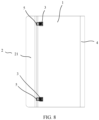
- a connection path between the first antenna 04 and the right middle frame 03 is a grounding path, that is, the grounding path of the first antenna 04 is a path a shown in FIG. 1 .
- a connection path between the second antenna 05 and the left middle frame 02 is a grounding path, that is, the grounding path of the second antenna 05 is a path b shown in FIG. 1 .
- both the grounding path a and the grounding path b are shortest grounding paths.
- the left middle frame 02 and the right middle frame 03 may be directly overlapped together, and are communicated with each other through two planes that are in contact with each other.
- a contact manner cannot ensure a close connection, the electrical connection and contact may be poor, electrical conductivity is very unstable, and the performance of the antenna cannot be ensured.
- the left middle frame 02 and the right middle frame 03 are prevented from coming into contact through insulation, the foregoing problem in which the performance of the antenna is affected because the grounding path of the antenna is not the shortest grounding path when the electronic device is in the folded state occurs.
- the first elastic component 3 may elastically and electrically connect the first electric-conductor to the second electric-conductor when the first enclosure 1 and the second enclosure 2 are in the folded state.
- a grounding path is constructed by using the first elastic component when the electronic device is in the folded state
- the first elastic component 3 may be disposed based on a position of an antenna and a shortest grounding path that can be implemented by the antenna, thereby adapting to a shortest grounding design of the electronic device in the folded state to prevent deterioration of performance of the antenna.
- the elastic electrical connection is close and poor contact does not occur.
- the enclosure 1 includes the first electric-conductor and the second enclosure 2 includes the second electric-conductor means that the electronic device generally has a grounding end.
- the grounding end may be an electrically conductive enclosure (for example, an enclosure made of a conductive metal), or may be another part disposed in the enclosure. Therefore, the enclosure may be made of a non-conductive material such as plastic, and cannot be directly used as a grounding end. Therefore, it is defined herein that the first enclosure 1 includes the first electric-conductor and the second enclosure 2 includes the second electric-conductor.
- the mechanical part engaging with and abutting against the first elastic component 3 may be implemented in a plurality of manners.
- the electronic device further includes a second elastic component, the second elastic component is disposed in the second enclosure 2, the second elastic component is disposed in correspondence with the first elastic component 3, the first elastic component 3 abuts against the second elastic component when the first enclosure 1 and the second enclosure 2 are in the folded state, and the first electric-conductor and the second electric-conductor are electrically connected to the second elastic component through the first elastic component 3.
- the second enclosure 2 is provided with the second elastic component. When the first enclosure and the second enclosure are in the folded state, the two elastic contact components engage with and abut against each other. An operation is labor-saving on the premise of ensuring an elastic electrical connection.
- a specific structure of the second elastic component may be consistent with a specific structure of the first elastic component 3.
- the second enclosure 2 is provided with a protrusion 5 in correspondence with the first elastic component 3, the protrusion 5 is disposed in correspondence with the first elastic component 3, and the first elastic component 3 abuts against the protrusion 5 when the first enclosure 1 and the second enclosure 2 are in the folded state.
- the protrusion 5 can be disposed easily, facilitating production and layout.
- the cooperation between the protrusion 5 and the first elastic component 3 may be implemented through cooperation between end portions of the two parts or through cooperation between side walls of the two parts.
- a part of the first elastic component 3 may be located outside the first enclosure 1.
- the first elastic component 3 when the first enclosure and the second enclosure are in the folded state, the first elastic component 3 is squeezed by the second enclosure 2 and is elastically and electrically connected to the second enclosure 2.
- the first enclosure 1 is elastically and electrically connected to the second enclosure 2 through the first elastic component 3.
- the first elastic component 3 is squeezed by the second enclosure 2, so that the first elastic component 3 has an elastic force against the second enclosure 2. In this way, it can be ensured that the first elastic component 3 is in closer contact with the second enclosure 2 and the electrical connection is more reliable.
- the first enclosure 1 is provided with a mounting groove 11, a first end of the first elastic component 3 is disposed in the mounting groove 11, the first end of the first elastic component 3 is connected to the first enclosure 1, and a second end of the first elastic component 3 extends out of the mounting groove 11.
- the first elastic component 3 may be implemented in a plurality of manners, provided that the first elastic component 3 can be elastically deformed and can connect the first enclosure 1 to the second enclosure 2.
- the first elastic component 3 may include an elastic mechanical part 31 and a contact member 32.
- the elastic mechanical part 31 is configured to be elastically deformed under a force and generate an elastic force in a direction opposite to a force bearing direction.
- the contact member 32 is configured to connect to and come into contact with the second enclosure 2. Specifically, as shown in FIG. 10 and FIG.
- the first elastic component 3 includes an elastic mechanical part 31 and a contact member 32, a first end of the elastic mechanical part 31 is the first end of the first elastic component 3 and is located in the mounting groove 11, the first end of the elastic mechanical part 31 is connected to the first enclosure 1, a second end of the elastic mechanical part 31 is connected to a first end of the contact member 32, and a second end of the contact member 32 is the second end of the first elastic component 3 and extends out of the mounting groove 11.
- the contact member 32 may be ejected out of the mounting groove 11 by the elastic mechanical part 31 and is separated from the elastic mechanical part 31. Therefore, specifically, as shown in FIG. 16 , FIG. 17, and FIG. 18 , a side of the mounting groove 11 facing toward the second enclosure 2 is provided with an opening 111. As shown in FIG. 15 and FIG.
- the elastic mechanical part 31 needs to be elastically deformed, and may be implemented in a plurality of manners, for example, an elastic block made of an elastic material or a spring.
- the spring is a manner that may be easily implemented.
- the elastic mechanical part 31 is a spring.
- a structure matching the spring needs to be disposed. For example, as shown in FIG. 13 and FIG.
- the electronic device further includes a first sleeve 33 and a second sleeve 34, the first sleeve 33 is slidably sleeved on the second sleeve 34, the first sleeve 33 and the second sleeve 34 are disposed in the mounting groove 11, and the spring is disposed in the first sleeve 33 and the second sleeve 34.
- the first sleeve 33 and the second sleeve 34 on which the first sleeve 33 is slidably sleeved not only can protect the spring, but also can guide and cooperate with an elastic motion of the spring.
- a specific implementation in which the first sleeve is slidably sleeved on the second sleeve may be that, as shown in FIG. 13 and FIG. 14 , the elastic mechanical part 31 is a spring, and the first elastic component 3 further includes the first sleeve 33 and the second sleeve 34 that are configured to accommodate the spring 31. As shown in FIG. 15 , the first sleeve 33 is fastened to the mounting groove 11, an extension direction of the first sleeve 33 is consistent with that of the second sleeve 34, and the first sleeve 33 and the second sleeve 34 are slidably sleeved together.
- An end of the first sleeve 33 and an end of the second sleeve 34 each have an opening, and the opening of the first sleeve 33 is opposite to the opening of the second sleeve 34.
- An extension direction of the spring is consistent with that of the first sleeve 33. Further, the spring may be located in the first sleeve 33.
- the first elastic component 3 is elastically deformed and is further connected to the second enclosure 2 only after being squeezed by the second enclosure 2.
- the first elastic component 3 extends out of the first enclosure 1, in the folding process of the electronic device, a side of the first elastic component 3 may come into contact with the second enclosure 2 first, and it is possible that the first elastic component 3 can only prevent the electronic device from being folded and cannot be elastically deformed normally.
- an edge of the first elastic component 3 first coming into contact with the second enclosure 2 needs to be provided with a slope that can provide guidance, so that the first elastic component 3 slides and comes into contact with the second enclosure 2 through the slope when the electronic device is folded and an end portion of the first elastic component 3 abuts against the second enclosure 2. Further, the first elastic component 3 can be elastically deformed successfully, and is elastically in contact with and connected to the second enclosure 2. Therefore, as shown in FIG. 13, FIG. 14 , and FIG. 15 , a side of the first elastic component 3 close to the second enclosure 2 is provided with a guiding slope 36. In the folding process of the electronic device, when the contact member 32 is in contact with the second enclosure 2, the guiding slope 36 is configured to guide the first elastic component 3 to be elastically deformed toward an inner portion of the first enclosure 1.
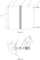
- the first elastic component 3 may be disposed based on an actual requirement. Generally, an available space inside the electronic device is small and a plurality of other functional members need to be mounted to implement other required functions, for example, a processor, a camera, and a voice output. Therefore, a space reserved for the antenna is limited, and the first elastic component 3 may be disposed at a position close to the antenna. As shown in FIG. 5 and FIG. 6 , the first enclosure 1 is articulated with the second enclosure 2 through an articulated shaft 4. The first elastic component 3 is disposed on a side of the first enclosure 1 far away from the articulated shaft 4.
- the first elastic component 3 When the first enclosure and the second enclosure are in the folded state, the first elastic component 3 is elastically deformed, and the first elastic component 3 may be communicated with a side of the second enclosure 2 far away from the articulated shaft 4, to elastically and electrically connect the first enclosure 1 to the second enclosure 2.
- both the first enclosure 1 and the second enclosure 2 can be electrically conductive.
- the first elastic component 3 elastically and electrically connects the first enclosure 1 to the second enclosure 2, so that the first enclosure 1 may be communicated with the second enclosure 2 through the first elastic component 3.
- first elastic component 3 is disposed on a side of the first enclosure 1 far away from the articulated shaft 4, when the first enclosure and the second enclosure are in the folded state, two opposite side plates of the first enclosure 1 and the second enclosure 2 may be separately connected, to be specific, may be connected to the first elastic component 3 and the articulated shaft 4. In this way, if the position of the antenna is closer to the articulated shaft 4, the antenna may be communicated with the first enclosure 1 and the second enclosure 2 through the articulated shaft 4, and a grounding path is shorter. If the position of the antenna is closer to the first elastic component 3, the antenna may be communicated with the first enclosure 1 and the second enclosure 2 through the first elastic component 3, and a grounding path is shorter.
- an end of the contact member 32 is in contact with and connected to the second enclosure 2.
- the first enclosure 1 may be communicated with the second enclosure 2 by using a connection relationship between the elastic mechanical part 31, the contact member 32, and the first enclosure 1.
- an elastomer 322 is fastened to the first elastic component 3, and an elastic free end of the elastomer 322 is slidably and elastically in contact with and connected to the first enclosure 1. To ensure a stable electrical connection between the first enclosure 1 and the second enclosure 2, the elastomer 322 is disposed.
- An end of the elastomer 322 is fastened to the first elastic component 3, and another end is the elastic free end and is slidably and elastically in contact with and connected to the first enclosure 1.
- the first elastic component 3 undergoes an elastic deformation toward the inner portion of the first enclosure 1, and the elastomer 322 fastened to the first elastic component 3 moves with the deformation.
- the elastomer 322 is always slidably and elastically in contact with and connected to the first enclosure 1. Therefore, the stable electrical connection between the first enclosure 1 and the second enclosure 2 can be ensured.
- each first elastic component 3 and the second enclosure 2 may be a nearest grounding path of an antenna, and a plurality of antennas can be grounded through a shortest path in different positional conditions.
- the elastic contact component can be connected to the end portion of the right middle frame 03 only after thicknesses of the left middle frame 02 and the right middle frame 03 are eliminated.
- the first elastic component 3 may need to be configured as a structure with a bending portion, or a bending structure may need to be disposed on the second enclosure 2.
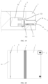
- such a solution does not facilitate production and assembly and is not beautiful enough. Therefore, as shown in FIG. 3 and FIG.
- a side edge of the second enclosure 2 is provided with a thickness cooperation portion 21, a thickness of the thickness cooperation portion 21 is greater than or equal to a sum of the thicknesses of the first enclosure 1 and the second enclosure 2, and the first elastic component 3 elastically and electrically connects the side edge of the first enclosure 1 to the thickness cooperation portion 21 of the second enclosure 2 when the first enclosure and the second enclosure are in the folded state.
- the first elastic component 3 may be elastically and electrically connected to the thickness cooperation portion 21 when the first enclosure and the second enclosure are in the folded state.
- no structure with a bending portion needs to be disposed inside the first elastic component 3, nor a bending structure needs to be disposed on the second enclosure 2.
- a shape of the thickness cooperation portion 21 may be configured based on the shape of the second enclosure 2 to ensure the appearance effect.
- the thickness cooperation portion 21 may be integrated with the second enclosure 2 and is a part of the second enclosure 2. As shown in FIG. 3 and FIG. 4 , the thickness cooperation portion 21 is a bumped structure disposed on the end portion of the second enclosure 2. Optionally, the thickness of the thickness cooperation portion 21 is equal to a sum of the thicknesses of the first enclosure 1 and the second enclosure 2. In this way, as shown in FIG. 4 , after the electronic device is folded, an outer surface of the first enclosure 1 is aligned with a surface of the thickness cooperation portion 21, improving the appearance effect.
- the first elastic component 3 when the first enclosure and the second enclosure are in the unfolded state, the first elastic component 3 may be completely located in the inner portion of the first enclosure.
- the first elastic component 3 is located in the inner portion of the first enclosure 1
- the second enclosure 2 is provided with a magnetic part in correspondence with the first elastic component 3
- the magnetic part is disposed in correspondence with the first elastic component 3.
- the first enclosure 1 is provided with a mounting groove 11, the first end of the first elastic component 3 is connected to the first enclosure 1, and the second end of the first elastic component 3 is located in the mounting groove 11 when the first enclosure 1 and the second enclosure 2 are in the unfolded state.
- the second end of the first elastic component 3 is attracted by the magnetic part, the first elastic component 3 extends out of the mounting groove 11, and the first electric-conductor and the second electric-conductor are electrically connected to the magnetic part through the first elastic component 3.
- the first elastic component 3 is located in the mounting groove 11 and can be well hidden to improve an appearance effect of the electronic device. In addition, this can be easily implemented in an attraction manner by using the magnetic part, no extra force needs to be applied, and the part cannot be damaged easily.
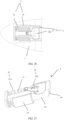
- FIG. 20 and FIG. 21 are both schematic diagrams of the structure in the unfolded state.
- the first elastic component 3 in FIG. 20 is shown in perspective merely for ease of identifying the position of the first elastic component 3.
- An actual appearance of the electronic device in this embodiment is shown in FIG. 21 .
- FIG. 23 is a schematic diagram of a structure in the folded state.
- the first elastic component 3 may be implemented in a plurality of manners, provided that the first elastic component 3 can be elastically deformed and can connect the first enclosure 1 to the second enclosure 2.
- the first elastic component 3 may include an elastic mechanical part 31 and a contact member 32.
- the elastic mechanical part 31 is configured to be elastically deformed under a force and generate an elastic force in a direction opposite to a force bearing direction.
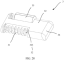
- the contact member 32 is configured to connect to and come into contact with the second enclosure 2. Specifically, as shown in FIG. 24, FIG. 25 , and FIG.
- the first elastic component 3 includes an elastic mechanical part 31 and a contact member 32, a first end of the elastic mechanical part 31 is the first end of the first elastic component 3 and is disposed in the mounting groove 1, the first end of the elastic mechanical part 31 is connected to the first enclosure 1, a second end of the elastic mechanical part 31 is connected to a first end of the contact member 32, and a second end of the contact member 32 is the second end of the first elastic component 3 and is located in the mounting groove 11. In this way, the two ends of the elastic mechanical part 31 are respectively connected to the first enclosure 1 and the contact member 32.
- the contact member 32 When the first enclosure and the second enclosure are in the folded state, the contact member 32 is attracted by the magnetic part of the second enclosure 2, and the elastic mechanical part 31 is elastically deformed, so that the contact member 32 can move toward the second enclosure 2 to come into contact with and connect to the second enclosure 2.
- the first elastic component 3 In the solution in which the first elastic component 3 is completely located in the mounting groove 11 when the first enclosure and the second enclosure are in the unfolded state, the first elastic component 1 is attracted by the magnetic part when the first enclosure and the second enclosure are in the folded state.
- the first elastic component 3 may be implemented in a plurality of manners. For example, as shown in Embodiment 1 and FIG. 12 , a first end of the elastic mechanical part 31 is fixedly connected to and abuts against the first enclosure 1, and another end of the elastic mechanical part 31 is fixedly connected to and abuts against the contact member 32.
- a fixed connection manner includes, but is not limited to, a buckle connection, welding, riveting, or the like.
- a first end of the elastic mechanical part 31 abuts against and is connected to the first enclosure 1, and another end of the elastic mechanical part 31 abuts against and is connected to the contact member 32.
- the elastic mechanical part 31 is a spring
- the first elastic component 3 further includes a spring sleeve 35 configured to accommodate the spring
- the contact member 32 is provided with an accommodation groove 323
- the elastic mechanical part 31 is located in the accommodation groove 323
- the spring sleeve 35 is fixedly connected to the first enclosure 1
- an end of the spring sleeve 35 facing toward an inner portion of the first enclosure 1 has an opening
- an end of the spring extends out of the opening of the spring sleeve 35 and is connected to an inner wall of the accommodation groove 323.
Landscapes
- Engineering & Computer Science (AREA)
- Computer Hardware Design (AREA)
- General Engineering & Computer Science (AREA)
- Theoretical Computer Science (AREA)
- Physics & Mathematics (AREA)
- Signal Processing (AREA)
- General Physics & Mathematics (AREA)
- Human Computer Interaction (AREA)
- Microelectronics & Electronic Packaging (AREA)
- Mechanical Engineering (AREA)
- Ocean & Marine Engineering (AREA)
- Computer Networks & Wireless Communication (AREA)
- Mathematical Physics (AREA)
- Casings For Electric Apparatus (AREA)
- Telephone Set Structure (AREA)
Claims (15)
- Elektronische Vorrichtung, wobei die elektronische Vorrichtung Folgendes umfasst:eine rotierende Welle (4);eine erste Umhüllung (1) und eine zweite Umhüllung (2), wobei die erste Umhüllung drehbar mit der zweiten Umhüllung durch die rotierende Welle verbunden ist, die erste Umhüllung einen ersten elektrischen Leiter umfasst, die zweite Umhüllung einen zweiten elektrischen Leiter umfasst und der erste elektrische Leiter mit dem zweiten elektrischen Leiter durch die rotierende Welle elektrisch verbunden ist, wenn sich die erste Umhüllung und die zweite Umhüllung in einem entfalteten Zustand befinden;gekennzeichnet durch eine erste elastische Komponente (3), wobei die erste elastische Komponente elektrisch leitfähig ist, die erste elastische Komponente elektrisch mit zumindest einem des ersten oder des zweiten elektrischen Leiters verbunden ist und die erste elastische Komponente in der ersten Umhüllung angeordnet ist; undder erste elektrische Leiter elektrisch mit dem zweiten elektrischen Leiter durch die erste elastische Komponente verbunden ist, wenn sich die erste Umhüllung und die zweite Umhüllung in einem gefalteten Zustand befinden.
- Elektronische Vorrichtung nach Anspruch 1, wobei die elektronische Vorrichtung ferner eine zweite elastische Komponente umfasst, die zweite elastische Komponente in der zweiten Umhüllung angeordnet ist, die zweite elastische Komponente in Übereinstimmung mit der ersten elastischen Komponente angeordnet ist, die erste elastische Komponente an der zweiten elastischen Komponente anliegt, wenn sich die erste Umhüllung und die zweite Umhüllung in dem gefalteten Zustand befinden, und der erste elektrische Leiter und der zweite elektrische Leiter mit der zweiten elastischen Komponente durch die erste elastische Komponente elektrisch verbunden sind.
- Elektronische Vorrichtung nach Anspruch 1, wobei die zweite Umhüllung mit einem Vorsprung (5) oder einer Vertiefung bereitgestellt ist, der Vorsprung oder die Vertiefung in Übereinstimmung mit der ersten elastischen Komponente angeordnet ist und die erste elastische Komponente mit dem Vorsprung oder der Vertiefung in Eingriff steht und an diesem/dieser anliegt, wenn sich die erste Umhüllung und die zweite Umhüllung in dem gefalteten Zustand befinden.
- Elektronische Vorrichtung nach einem der Ansprüche 1 bis 3, wobei die erste Umhüllung mit einer Befestigungsnut (11) bereitgestellt ist, ein erstes Ende der ersten elastischen Komponente in der Befestigungsnut angeordnet ist, das erste Ende der ersten elastischen Komponente mit der ersten Umhüllung verbunden ist und sich ein zweites Ende der ersten elastischen Komponente aus der Befestigungsnut heraus erstreckt.
- Elektronische Vorrichtung nach Anspruch 4, wobei die erste elastische Komponente ein elastisches mechanisches Teil (31) und ein Kontaktelement (32) umfasst, ein erstes Ende des elastischen mechanischen Teils das erste Ende der ersten elastischen Komponente ist und in der Befestigungsnut angeordnet und mit der ersten Umhüllung verbunden ist, ein zweites Ende des elastischen mechanischen Teils mit einem ersten Ende des Kontaktelements verbunden ist und ein zweites Ende des Kontaktelements das zweite Ende der ersten elastischen Komponente ist und sich aus der Befestigungsnut heraus erstreckt.
- Elektronische Vorrichtung nach Anspruch 5, wobei das erste Ende des elastischen mechanischen Teils fest mit der ersten Umhüllung und das zweite Ende des elastischen mechanischen Teils fest mit dem ersten Ende des Kontaktelements verbunden ist.
- Elektronische Vorrichtung nach Anspruch 5, wobei das erste Ende des elastischen mechanischen Teils an der ersten Umhüllung anliegt und mit dieser verbunden ist und das zweite Ende des elastischen mechanischen Teils an dem ersten Ende des Kontaktelements anliegt und mit diesem verbunden ist.
- Elektronische Vorrichtung nach Anspruch 7, wobei eine Seite der Befestigungsnut, die der zweiten Umhüllung zugewandt ist, mit einer Öffnung (111) bereitgestellt ist, eine Form der Öffnung zu dem Kontaktelement passt, sich das erste Ende des Kontaktelements in der Befestigungsnut befindet, das erste Ende des Kontaktelements einen Positionsbegrenzer (321) umfasst, eine Außenkontur des Positionsbegrenzers größer als die Öffnung der Befestigungsnut ist und sich das zweite Ende des Kontaktelements aus der Öffnung der Befestigungsnut heraus erstreckt.
- Elektronische Vorrichtung nach einem der Ansprüche 5 bis 8, wobei das elastische mechanische Teil eine Feder ist;die elektronische Vorrichtung ferner eine erste Hülse (33) und eine zweite Hülse (34) umfasst und die erste Hülse gleitbar auf die zweite Hülse geschoben ist; unddie erste Hülse und die zweite Hülse in der Befestigungsnut angeordnet sind und die Feder in der ersten Hülse und der zweiten Hülse angeordnet ist.
- Elektronische Vorrichtung nach einem der Ansprüche 4 bis 9, wobei eine Endfläche des zweiten Endes der ersten elastischen Komponente eine Steigung (36) ist.
- Elektronische Vorrichtung nach einem der Ansprüche 1 bis 3, wobei die zweite Umhüllung mit einem magnetischen Teil bereitgestellt ist und das magnetische Teil in Übereinstimmung mit der ersten elastischen Komponente angeordnet ist;die erste Umhüllung mit einer Befestigungsnut (11) bereitgestellt ist, ein erstes Ende der ersten elastischen Komponente in der Befestigungsnut angeordnet ist und mit der ersten Umhüllung verbunden ist und sich ein zweites Ende der ersten elastischen Komponente in der Befestigungsnut befindet, wenn sich die erste Umhüllung und die zweite Umhüllung in dem entfalteten Zustand befinden; undwenn sich die erste Umhüllung und die zweite Umhüllung in dem gefalteten Zustand befinden, das zweite Ende der ersten elastischen Komponente durch das magnetische Teil angezogen wird, sich die erste elastische Komponente aus der Befestigungsnut heraus erstreckt und der erste elektrische Leiter und der zweite elektrische Leiter durch die erste elastische Komponente mit dem magnetischen Teil elektrisch verbunden sind.
- Elektronische Vorrichtung nach Anspruch 11, wobei die erste elastische Komponente ein elastisches mechanisches Teil (31) und ein Kontaktelement (32) umfasst, ein erstes Ende des elastischen mechanischen Teils das erste Ende der ersten elastischen Komponente ist und in der Befestigungsnut angeordnet ist, das erste Ende des elastischen mechanischen Teils mit der ersten Umhüllung verbunden ist, ein zweites Ende des elastischen mechanischen Teils mit einem ersten Ende des Kontaktelements verbunden ist, ein zweites Ende des Kontaktelements das zweite Ende der ersten elastischen Komponente ist und sich das zweite Ende des Kontaktelements in der Befestigungsnut befindet, wenn sich die erste Umhüllung und die zweite Umhüllung in dem entfalteten Zustand befinden.
- Elektronische Vorrichtung nach Anspruch 12, wobei das erste Ende des elastischen mechanischen Teils fest mit der ersten Umhüllung und das zweite Ende des elastischen mechanischen Teils fest mit dem ersten Ende des Kontaktelements verbunden ist.
- Elektronische Vorrichtung nach Anspruch 12, wobei das erste Ende des elastischen mechanischen Teils an der ersten Umhüllung anliegt und mit dieser verbunden ist und das zweite Ende des elastischen mechanischen Teils an dem ersten Ende des Kontaktelements anliegt und mit diesem verbunden ist.
- Elektronische Vorrichtung nach einem der Ansprüche 12 bis 14, wobei das elastische mechanische Teil eine Feder ist, die erste elastische Komponente ferner eine Federhülse (35) umfasst, die dazu konfiguriert ist, die Feder aufzunehmen, das Kontaktelement mit einer Aufnahmenut (323) bereitgestellt ist, sich sowohl das elastische mechanische Teil als auch die Federhülse in der Aufnahmenut befinden, die Federhülse fest mit der ersten Umhüllung verbunden ist, ein Ende der Federhülse, das einem Innenabschnitt der ersten Umhüllung zugewandt ist, eine Öffnung aufweist und sich ein Ende der Feder aus der Öffnung der Federhülse heraus erstreckt und an einer Innenwand der Aufnahmenut anliegt und mit dieser verbunden ist.
Applications Claiming Priority (2)
| Application Number | Priority Date | Filing Date | Title |
|---|---|---|---|
| CN201911077714.1A CN112769980B (zh) | 2019-11-06 | 2019-11-06 | 一种电子设备 |
| PCT/CN2020/126794 WO2021088928A1 (zh) | 2019-11-06 | 2020-11-05 | 一种电子设备 |
Publications (3)
| Publication Number | Publication Date |
|---|---|
| EP4044565A1 EP4044565A1 (de) | 2022-08-17 |
| EP4044565A4 EP4044565A4 (de) | 2022-12-14 |
| EP4044565B1 true EP4044565B1 (de) | 2025-01-22 |
Family
ID=75692698
Family Applications (1)
| Application Number | Title | Priority Date | Filing Date |
|---|---|---|---|
| EP20883706.2A Active EP4044565B1 (de) | 2019-11-06 | 2020-11-05 | Elektronische vorrichtung |
Country Status (4)
| Country | Link |
|---|---|
| US (1) | US12356568B2 (de) |
| EP (1) | EP4044565B1 (de) |
| CN (1) | CN112769980B (de) |
| WO (1) | WO2021088928A1 (de) |
Families Citing this family (2)
| Publication number | Priority date | Publication date | Assignee | Title |
|---|---|---|---|---|
| CN115459010B (zh) * | 2022-09-30 | 2025-04-08 | Oppo广东移动通信有限公司 | 锁定机构、壳体及电子设备 |
| CN119712702B (zh) * | 2023-09-28 | 2025-11-11 | 华为终端有限公司 | 一种转轴机构以及电子设备 |
Family Cites Families (27)
| Publication number | Priority date | Publication date | Assignee | Title |
|---|---|---|---|---|
| US6035032A (en) * | 1998-03-19 | 2000-03-07 | Lucent Technologies Inc. | Multi-layered foldable cross connect field |
| US6114958A (en) * | 1998-06-19 | 2000-09-05 | Micron Electronics, Inc. | System and method for indicating when a stylus of a computer is missing |
| JP4403687B2 (ja) | 2002-09-18 | 2010-01-27 | ソニー株式会社 | 固体撮像装置およびその駆動制御方法 |
| US20060046792A1 (en) * | 2004-08-31 | 2006-03-02 | Hassemer Brian J | Hinge apparatus and methods therefor |
| JP2006129386A (ja) | 2004-11-01 | 2006-05-18 | Fujitsu Ltd | アンテナ装置及び無線通信装置 |
| US20060133019A1 (en) * | 2004-12-21 | 2006-06-22 | Fuminori Yamazaki | Latch assembly for an electronic device |
| JP4497366B2 (ja) | 2005-02-04 | 2010-07-07 | 国立大学法人東北大学 | 光センサおよび固体撮像装置 |
| US20070021161A1 (en) * | 2005-07-19 | 2007-01-25 | Nokia Corporation | Hand-portable radio communications device comprising relatively movable first and second portions |
| US20070184709A1 (en) * | 2006-02-06 | 2007-08-09 | Motorola, Inc. | Method and apparatus for a flexible circuit and hinge |
| KR101553722B1 (ko) * | 2007-06-22 | 2015-09-16 | 노키아 코포레이션 | 안테나 장치 |
| US20090201400A1 (en) | 2008-02-08 | 2009-08-13 | Omnivision Technologies, Inc. | Backside illuminated image sensor with global shutter and storage capacitor |
| CN103354603A (zh) | 2009-09-30 | 2013-10-16 | 英属开曼群岛商恒景科技股份有限公司 | 影像传感器、对其进行相关双取样及同步电子快门的方法 |
| US8593800B2 (en) * | 2009-11-05 | 2013-11-26 | Panasonic Corporation | Electronic equipment with hinge mechanism |
| JP2014060519A (ja) | 2012-09-14 | 2014-04-03 | Sony Corp | 固体撮像素子及びその制御方法、並びに電子機器 |
| TWI566390B (zh) | 2014-10-31 | 2017-01-11 | 力晶科技股份有限公司 | 能改善像素動態範圍的cmos影像感應器 |
| CN106355996B (zh) | 2016-11-23 | 2019-05-07 | 上海天马微电子有限公司 | 柔性显示装置 |
| CN107465433A (zh) | 2017-08-31 | 2017-12-12 | 珠海格力电器股份有限公司 | 一种可折叠移动终端 |
| CN207184560U (zh) | 2017-09-05 | 2018-04-03 | 广东欧珀移动通信有限公司 | 可折叠移动终端及其折叠机构 |
| CN109494477B (zh) * | 2017-09-12 | 2022-01-07 | 中兴通讯股份有限公司 | 设备天线及可折叠设备 |
| CN109167153B (zh) * | 2018-08-29 | 2021-03-02 | Oppo广东移动通信有限公司 | 电子设备、天线辐射体控制方法及存储介质 |
| CN109167154B (zh) * | 2018-08-29 | 2020-06-16 | Oppo广东移动通信有限公司 | 电子设备 |
| CN209015004U (zh) | 2018-09-17 | 2019-06-21 | 华中科技大学同济医学院附属协和医院 | 一种可折叠屏幕 |
| CN209029529U (zh) * | 2018-10-29 | 2019-06-25 | 深圳市柔宇科技有限公司 | 天线装置及具有该天线装置的电子设备 |
| CN109638451B (zh) | 2018-12-12 | 2021-04-23 | 维沃移动通信有限公司 | 一种移动终端及天线控制方法 |
| CN109618030B (zh) * | 2018-12-20 | 2021-07-13 | 维沃移动通信有限公司 | 一种终端设备 |
| CN110277642B (zh) * | 2019-07-15 | 2021-02-02 | 青岛海信移动通信技术股份有限公司 | 移动终端 |
| CN212163393U (zh) * | 2019-11-06 | 2020-12-15 | 华为技术有限公司 | 一种电子设备 |
-
2019
- 2019-11-06 CN CN201911077714.1A patent/CN112769980B/zh active Active
-
2020
- 2020-11-05 US US17/774,336 patent/US12356568B2/en active Active
- 2020-11-05 EP EP20883706.2A patent/EP4044565B1/de active Active
- 2020-11-05 WO PCT/CN2020/126794 patent/WO2021088928A1/zh not_active Ceased
Also Published As
| Publication number | Publication date |
|---|---|
| CN112769980A (zh) | 2021-05-07 |
| CN112769980B (zh) | 2025-02-07 |
| US20220408579A1 (en) | 2022-12-22 |
| EP4044565A4 (de) | 2022-12-14 |
| US12356568B2 (en) | 2025-07-08 |
| EP4044565A1 (de) | 2022-08-17 |
| WO2021088928A1 (zh) | 2021-05-14 |
Similar Documents
| Publication | Publication Date | Title |
|---|---|---|
| US10383241B2 (en) | Capping member, housing assembly, and electronic | |
| US10416726B2 (en) | Housing assembly and electronic device | |
| US10268245B2 (en) | Housing assembly and electronic device | |
| US10274996B2 (en) | Coupling member, housing assembly and electronic device | |
| US10268237B2 (en) | Housing assembly and electronic device | |
| EP3355161B1 (de) | Verbindungselement, gehäuseanordnung und elektronische vorrichtung | |
| US10452097B2 (en) | Electronic device | |
| US10268244B2 (en) | Housing assembly and electronic device | |
| EP4044565B1 (de) | Elektronische vorrichtung | |
| JP2003069441A (ja) | 折り畳み型携帯無線機 | |
| CN212163393U (zh) | 一种电子设备 | |
| JP4525516B2 (ja) | 折畳み型携帯端末 | |
| KR20250052932A (ko) | 안테나를 포함하는 전자 장치 |
Legal Events
| Date | Code | Title | Description |
|---|---|---|---|
| STAA | Information on the status of an ep patent application or granted ep patent |
Free format text: STATUS: THE INTERNATIONAL PUBLICATION HAS BEEN MADE |
|
| PUAI | Public reference made under article 153(3) epc to a published international application that has entered the european phase |
Free format text: ORIGINAL CODE: 0009012 |
|
| STAA | Information on the status of an ep patent application or granted ep patent |
Free format text: STATUS: REQUEST FOR EXAMINATION WAS MADE |
|
| 17P | Request for examination filed |
Effective date: 20220511 |
|
| AK | Designated contracting states |
Kind code of ref document: A1 Designated state(s): AL AT BE BG CH CY CZ DE DK EE ES FI FR GB GR HR HU IE IS IT LI LT LU LV MC MK MT NL NO PL PT RO RS SE SI SK SM TR |
|
| A4 | Supplementary search report drawn up and despatched |
Effective date: 20221111 |
|
| RIC1 | Information provided on ipc code assigned before grant |
Ipc: G06F 1/16 20060101ALI20221107BHEP Ipc: H04M 1/02 20060101AFI20221107BHEP |
|
| DAV | Request for validation of the european patent (deleted) | ||
| DAX | Request for extension of the european patent (deleted) | ||
| STAA | Information on the status of an ep patent application or granted ep patent |
Free format text: STATUS: EXAMINATION IS IN PROGRESS |
|
| 17Q | First examination report despatched |
Effective date: 20231114 |
|
| GRAP | Despatch of communication of intention to grant a patent |
Free format text: ORIGINAL CODE: EPIDOSNIGR1 |
|
| STAA | Information on the status of an ep patent application or granted ep patent |
Free format text: STATUS: GRANT OF PATENT IS INTENDED |
|
| INTG | Intention to grant announced |
Effective date: 20240911 |
|
| GRAS | Grant fee paid |
Free format text: ORIGINAL CODE: EPIDOSNIGR3 |
|
| GRAA | (expected) grant |
Free format text: ORIGINAL CODE: 0009210 |
|
| STAA | Information on the status of an ep patent application or granted ep patent |
Free format text: STATUS: THE PATENT HAS BEEN GRANTED |
|
| AK | Designated contracting states |
Kind code of ref document: B1 Designated state(s): AL AT BE BG CH CY CZ DE DK EE ES FI FR GB GR HR HU IE IS IT LI LT LU LV MC MK MT NL NO PL PT RO RS SE SI SK SM TR |
|
| REG | Reference to a national code |
Ref country code: GB Ref legal event code: FG4D |
|
| REG | Reference to a national code |
Ref country code: CH Ref legal event code: EP |
|
| REG | Reference to a national code |
Ref country code: IE Ref legal event code: FG4D |
|
| REG | Reference to a national code |
Ref country code: DE Ref legal event code: R096 Ref document number: 602020045337 Country of ref document: DE |
|
| REG | Reference to a national code |
Ref country code: NL Ref legal event code: MP Effective date: 20250122 |
|
| PG25 | Lapsed in a contracting state [announced via postgrant information from national office to epo] |
Ref country code: NL Free format text: LAPSE BECAUSE OF FAILURE TO SUBMIT A TRANSLATION OF THE DESCRIPTION OR TO PAY THE FEE WITHIN THE PRESCRIBED TIME-LIMIT Effective date: 20250122 |
|
| PG25 | Lapsed in a contracting state [announced via postgrant information from national office to epo] |
Ref country code: RS Free format text: LAPSE BECAUSE OF FAILURE TO SUBMIT A TRANSLATION OF THE DESCRIPTION OR TO PAY THE FEE WITHIN THE PRESCRIBED TIME-LIMIT Effective date: 20250422 |
|
| PG25 | Lapsed in a contracting state [announced via postgrant information from national office to epo] |
Ref country code: FI Free format text: LAPSE BECAUSE OF FAILURE TO SUBMIT A TRANSLATION OF THE DESCRIPTION OR TO PAY THE FEE WITHIN THE PRESCRIBED TIME-LIMIT Effective date: 20250122 |
|
| PG25 | Lapsed in a contracting state [announced via postgrant information from national office to epo] |
Ref country code: PL Free format text: LAPSE BECAUSE OF FAILURE TO SUBMIT A TRANSLATION OF THE DESCRIPTION OR TO PAY THE FEE WITHIN THE PRESCRIBED TIME-LIMIT Effective date: 20250122 |
|
| PG25 | Lapsed in a contracting state [announced via postgrant information from national office to epo] |
Ref country code: ES Free format text: LAPSE BECAUSE OF FAILURE TO SUBMIT A TRANSLATION OF THE DESCRIPTION OR TO PAY THE FEE WITHIN THE PRESCRIBED TIME-LIMIT Effective date: 20250122 |
|
| REG | Reference to a national code |
Ref country code: LT Ref legal event code: MG9D |
|
| PG25 | Lapsed in a contracting state [announced via postgrant information from national office to epo] |
Ref country code: IS Free format text: LAPSE BECAUSE OF FAILURE TO SUBMIT A TRANSLATION OF THE DESCRIPTION OR TO PAY THE FEE WITHIN THE PRESCRIBED TIME-LIMIT Effective date: 20250522 Ref country code: NO Free format text: LAPSE BECAUSE OF FAILURE TO SUBMIT A TRANSLATION OF THE DESCRIPTION OR TO PAY THE FEE WITHIN THE PRESCRIBED TIME-LIMIT Effective date: 20250422 |
|
| REG | Reference to a national code |
Ref country code: AT Ref legal event code: MK05 Ref document number: 1762341 Country of ref document: AT Kind code of ref document: T Effective date: 20250122 |
|
| PG25 | Lapsed in a contracting state [announced via postgrant information from national office to epo] |
Ref country code: HR Free format text: LAPSE BECAUSE OF FAILURE TO SUBMIT A TRANSLATION OF THE DESCRIPTION OR TO PAY THE FEE WITHIN THE PRESCRIBED TIME-LIMIT Effective date: 20250122 |
|
| PG25 | Lapsed in a contracting state [announced via postgrant information from national office to epo] |
Ref country code: PT Free format text: LAPSE BECAUSE OF FAILURE TO SUBMIT A TRANSLATION OF THE DESCRIPTION OR TO PAY THE FEE WITHIN THE PRESCRIBED TIME-LIMIT Effective date: 20250522 Ref country code: LV Free format text: LAPSE BECAUSE OF FAILURE TO SUBMIT A TRANSLATION OF THE DESCRIPTION OR TO PAY THE FEE WITHIN THE PRESCRIBED TIME-LIMIT Effective date: 20250122 |
|
| PG25 | Lapsed in a contracting state [announced via postgrant information from national office to epo] |
Ref country code: GR Free format text: LAPSE BECAUSE OF FAILURE TO SUBMIT A TRANSLATION OF THE DESCRIPTION OR TO PAY THE FEE WITHIN THE PRESCRIBED TIME-LIMIT Effective date: 20250423 Ref country code: BG Free format text: LAPSE BECAUSE OF FAILURE TO SUBMIT A TRANSLATION OF THE DESCRIPTION OR TO PAY THE FEE WITHIN THE PRESCRIBED TIME-LIMIT Effective date: 20250122 |
|
| PG25 | Lapsed in a contracting state [announced via postgrant information from national office to epo] |
Ref country code: AT Free format text: LAPSE BECAUSE OF FAILURE TO SUBMIT A TRANSLATION OF THE DESCRIPTION OR TO PAY THE FEE WITHIN THE PRESCRIBED TIME-LIMIT Effective date: 20250122 |
|
| PG25 | Lapsed in a contracting state [announced via postgrant information from national office to epo] |
Ref country code: SE Free format text: LAPSE BECAUSE OF FAILURE TO SUBMIT A TRANSLATION OF THE DESCRIPTION OR TO PAY THE FEE WITHIN THE PRESCRIBED TIME-LIMIT Effective date: 20250122 |
|
| PG25 | Lapsed in a contracting state [announced via postgrant information from national office to epo] |
Ref country code: SM Free format text: LAPSE BECAUSE OF FAILURE TO SUBMIT A TRANSLATION OF THE DESCRIPTION OR TO PAY THE FEE WITHIN THE PRESCRIBED TIME-LIMIT Effective date: 20250122 |
|
| PG25 | Lapsed in a contracting state [announced via postgrant information from national office to epo] |
Ref country code: DK Free format text: LAPSE BECAUSE OF FAILURE TO SUBMIT A TRANSLATION OF THE DESCRIPTION OR TO PAY THE FEE WITHIN THE PRESCRIBED TIME-LIMIT Effective date: 20250122 |
|
| PG25 | Lapsed in a contracting state [announced via postgrant information from national office to epo] |
Ref country code: IT Free format text: LAPSE BECAUSE OF FAILURE TO SUBMIT A TRANSLATION OF THE DESCRIPTION OR TO PAY THE FEE WITHIN THE PRESCRIBED TIME-LIMIT Effective date: 20250122 |
|
| PGFP | Annual fee paid to national office [announced via postgrant information from national office to epo] |
Ref country code: GB Payment date: 20250930 Year of fee payment: 6 |
|
| PG25 | Lapsed in a contracting state [announced via postgrant information from national office to epo] |
Ref country code: CZ Free format text: LAPSE BECAUSE OF FAILURE TO SUBMIT A TRANSLATION OF THE DESCRIPTION OR TO PAY THE FEE WITHIN THE PRESCRIBED TIME-LIMIT Effective date: 20250122 Ref country code: EE Free format text: LAPSE BECAUSE OF FAILURE TO SUBMIT A TRANSLATION OF THE DESCRIPTION OR TO PAY THE FEE WITHIN THE PRESCRIBED TIME-LIMIT Effective date: 20250122 |
|
| REG | Reference to a national code |
Ref country code: DE Ref legal event code: R097 Ref document number: 602020045337 Country of ref document: DE |
|
| PG25 | Lapsed in a contracting state [announced via postgrant information from national office to epo] |
Ref country code: RO Free format text: LAPSE BECAUSE OF FAILURE TO SUBMIT A TRANSLATION OF THE DESCRIPTION OR TO PAY THE FEE WITHIN THE PRESCRIBED TIME-LIMIT Effective date: 20250122 |
|
| PG25 | Lapsed in a contracting state [announced via postgrant information from national office to epo] |
Ref country code: SK Free format text: LAPSE BECAUSE OF FAILURE TO SUBMIT A TRANSLATION OF THE DESCRIPTION OR TO PAY THE FEE WITHIN THE PRESCRIBED TIME-LIMIT Effective date: 20250122 |
|
| PLBE | No opposition filed within time limit |
Free format text: ORIGINAL CODE: 0009261 |
|
| STAA | Information on the status of an ep patent application or granted ep patent |
Free format text: STATUS: NO OPPOSITION FILED WITHIN TIME LIMIT |
|
| 26N | No opposition filed |
Effective date: 20251023 |
|
| PGFP | Annual fee paid to national office [announced via postgrant information from national office to epo] |
Ref country code: DE Payment date: 20250930 Year of fee payment: 6 |