EP4044407A1 - Verbindungsstück für eine rotierende elektrische maschine - Google Patents
Verbindungsstück für eine rotierende elektrische maschine Download PDFInfo
- Publication number
- EP4044407A1 EP4044407A1 EP22155922.2A EP22155922A EP4044407A1 EP 4044407 A1 EP4044407 A1 EP 4044407A1 EP 22155922 A EP22155922 A EP 22155922A EP 4044407 A1 EP4044407 A1 EP 4044407A1
- Authority
- EP
- European Patent Office
- Prior art keywords
- electrical
- winding
- interconnector
- trace
- machine according
- Prior art date
- Legal status (The legal status is an assumption and is not a legal conclusion. Google has not performed a legal analysis and makes no representation as to the accuracy of the status listed.)
- Withdrawn
Links
Images


Classifications
-
- H—ELECTRICITY
- H02—GENERATION; CONVERSION OR DISTRIBUTION OF ELECTRIC POWER
- H02K—DYNAMO-ELECTRIC MACHINES
- H02K3/00—Details of windings
- H02K3/46—Fastening of windings on the stator or rotor structure
- H02K3/50—Fastening of winding heads, equalising connectors, or connections thereto
-
- H—ELECTRICITY
- H02—GENERATION; CONVERSION OR DISTRIBUTION OF ELECTRIC POWER
- H02K—DYNAMO-ELECTRIC MACHINES
- H02K11/00—Structural association of dynamo-electric machines with electric components or with devices for shielding, monitoring or protection
- H02K11/30—Structural association with control circuits or drive circuits
- H02K11/33—Drive circuits, e.g. power electronics
-
- H—ELECTRICITY
- H02—GENERATION; CONVERSION OR DISTRIBUTION OF ELECTRIC POWER
- H02K—DYNAMO-ELECTRIC MACHINES
- H02K2203/00—Specific aspects not provided for in the other groups of this subclass relating to the windings
- H02K2203/09—Machines characterised by wiring elements other than wires, e.g. bus rings, for connecting the winding terminations
-
- H—ELECTRICITY
- H02—GENERATION; CONVERSION OR DISTRIBUTION OF ELECTRIC POWER
- H02K—DYNAMO-ELECTRIC MACHINES
- H02K3/00—Details of windings
- H02K3/04—Windings characterised by the conductor shape, form or construction, e.g. with bar conductors
- H02K3/28—Layout of windings or of connections between windings
Definitions
- the invention relates in particular to a rotating electrical machine provided with an interconnector arranged to electrically connect an electrical winding of an active part such as a stator or a rotor to a voltage converter of the rotating electrical machine.
- a reversible machine is a rotating electric machine able to work in a reversible manner, on the one hand, as an electric generator in alternator function and, on the other hand, as an electric motor for example to provide torque to the vehicle.
- a vehicle is for example here a motor vehicle, a bicycle, a drone or any machine used to transport or move an element.
- a rotating electrical machine comprises a rotor that rotates about an axis and a fixed stator.
- alternator mode when the rotor is rotating, it induces a magnetic field in the stator which transforms it into electric current in order to supply the electrical consumers of the vehicle and recharge the battery.
- motor mode the stator is electrically powered and induces a magnetic field driving the rotor in rotation, for example to start or drive the heat engine or provide torque to the vehicle.
- rotating electrical machines must be increasingly powerful while presenting optimized efficiency and reduced bulk in order to reduce their weight and size and/or adapt to new applications and vehicles of the type drone, scooter, electric scooter, etc. It is therefore becoming necessary to optimize the design of rotating electrical machines to support these developments and adapt to new constraints.
- the subject of the present invention is therefore a rotating electrical machine comprising: a coiled part, forming in particular a stator or a rotor, the coiled part comprising a body and an electrical coil housed at least partially in the body and comprising a plurality of electrical conductors electrically connected together so as to form electrical phases of said winding, said winding being of the wave winding type, an interconnector arranged to electrically connect the electrical winding to electronic power modules of an electronic assembly of the rotating electrical machine, the interconnector comprising several electrical traces each having a first connection end arranged to electrically connect said trace with an associated power electronic module and a plurality of second connection ends, each being arranged to electrically connect said trace with a conductor of the electric winding.
- the interconnector comprises as many traces as the electric winding comprises electrical phase and each trace comprises at least four second connection ends.
- each electrical trace of the interconnector has a connecting portion arranged to connect the first connection end and the second connection ends. This makes it possible to simplify the manufacture of the interconnector and to limit the connection constraints between the elements.
- each trace is in one piece so that the first end, the connecting portion and the second ends are made in one piece with each other.
- each second connection end of a trace is electrically connected with only one electrical conductor of the winding. This makes it possible to simplify the making of the electrical connections.
- each electrical trace extends over only a portion of the circumference of the rotating electrical machine. This makes it possible to reduce the size of the interconnector.
- At least two of the second connection ends of the same electrical trace are respectively arranged to electrically connect electrical conductors of the electrical winding belonging to the same electrical phase. There is thus achieved, in a simple manner, a parallel connection of two electrical conductors of the same phase.
- each electrical trace is arranged to electrically connect two electrical phases of the electrical winding to each other.
- the electrical winding has a triangle coupling.
- Such coupling makes it possible to reduce the size of the interconnector by avoiding the formation of a neutral point.
- each second connection end has a minimum section of dimension greater than a maximum section of an electrical conductor with which said end is connected. This makes it possible to increase the electrical power which can be supported by the trace.
- the interconnector further comprises at least one casing formed from an electrically insulating material, said casing at least partially housing the electrical traces.
- the box makes it possible to electrically insulate the electrical traces between them, to protect them from the external environment and to simplify their assembly on the machine.
- the electrical winding comprises several phase systems, each system comprising at least two electrical phases and in that the interconnector comprises at least two interconnection sub-assemblies distinct from each other, each sub- interconnection assembly comprising electrical traces associated with the same phase system of the electrical winding.
- the phase systems are independent of each other so that there is no electrical connection between the phases of two distinct systems.
- the interconnection sub-assemblies are arranged diametrically opposite to each other on the circumference of the machine.
- the two interconnection subassemblies are symmetrical with respect to the axis of the machine.
- the rotating electrical machine further comprises at least one casing at least partially surrounding the coiled part, the interconnector being mounted on the casing. This makes it possible to simplify the fixing of the interconnector in the machine.
- the casing extends between the interconnector and the coiled part. This makes it possible to simplify the production of the interconnector by overcoming the problems of electrical insulation of the connections of the interconnector when the coiled part is at least partially housed in a chamber containing a cooling liquid.
- each phase of the electrical winding has at least two branches each formed of a plurality of electrical conductors electrically connected to each other, the branches of the same phase being electrically connected in parallel via the interconnector.
- each phase of the electrical winding has at least two windings each formed of a plurality of electrical conductors electrically connected to each other, the windings of the same phase being electrically connected in series via a connection pin electrical winding.
- connection pin has at least one conductive segment housed in a notch in the body.
- each branch of a phase comprises at least two windings electrically connected in series with each other.
- each electrical conductor comprises at least one conductive segment forming a conductive bar housed in a notch of the coiled part body and at least two connection ends, each connection end being connected to a connection end of another electrical conductor of the same phase or at a second connection end of the interconnector.
- the body of the coiled part has an annular yoke extending around an axis and a plurality of teeth extending from a side face of the yoke in a radial direction so as to delimit notches housing the electrical winding.
- the conductive segments of the electrical conductors, intended to be housed in the same notch form N layers.
- each notch comprises N segments belonging to different conductors.
- a layer is formed by a single segment.
- a phase of the winding comprises a first group of conductors whose conducting segments are arranged in two layers and a second group of conductors whose conducting segments are arranged in two layers, the layers comprising the first group of conductors being distinct from the layers comprising the second group of conductors.
- each group of conductors forms a winding.
- the connection pin makes it possible to connect the first group to the second group.
- the conductive segments of the same group of conductors are arranged in two radially adjacent layers.
- a phase of the winding comprises at least two electrical conductors, called supply pins, forming an input and an output.
- each power pin having a conductive segment having a first end connected to another electrical conductor of the same phase and a second end connected to a second connection end of an electrical trace of the interconnector.
- the power pins allow the winding to be connected to an electronic power and/or control module.
- each phase comprises a plurality of conventional hairpins of the first group, a plurality of hairpins conventional of the second group, at least one connecting pin and at least two power pins.
- the rotating electrical machine can advantageously form an alternator, an alternator-starter, a reversible machine or an electric motor.
- the present invention may be better understood on reading the detailed description which follows, non-limiting examples of implementation of the invention and examination of the appended drawings.
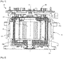
- the [ Fig. 1] and [Fig. 2 ] represent respectively, schematically and partially, a sectional view and a perspective view of a rotating electrical machine according to an example implementation of the invention.
- There [ Fig. 3 ] schematically represents a perspective view of the stator of the figure 1 or the figure 2 .
- There [ Fig. 4 ] schematically represents a schematic view of the winding of the figure 2 showing example of stator coupling.
- There [ Fig. 5 ] schematically represents a sectional view along a radial plane of part of the stator of the picture 3 .
- There [ Fig. 1] and [Fig. 2 ] represent respectively, schematically and partially, a sectional view and a perspective view of a rotating electrical machine according to an example implementation of the invention.
- There [ Fig. 3 ] schematically represents a perspective view of the stator of the
- FIG. 6 schematically represents a perspective view of a classic pin of the stator of the picture 3 .
- FIG. 7 schematically represents a perspective view of a connecting pin of the stator of the picture 3 .
- the [ Fig. 8] and [Fig. 9 ] schematically represent perspective views of a first power pin and a second power pin of the stator of the picture 3 .
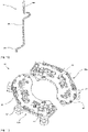
- FIG. 10 schematically represents a perspective view of the interconnector the example of the picture 2 .
- FIG. 11 schematically represents a perspective view of the interconnector traces of the figure 10 .
- the figures 1 and 2 represent an example of a compact and polyphase rotary electrical machine 10, in particular for a vehicle such as a motor vehicle.
- This machine 10 transforms mechanical energy into electrical energy, in alternator mode, and can operate in motor mode to transform electrical energy into mechanical energy.
- This rotating electrical machine 10 is, for example, an alternator, an alternator-starter, a reversible machine or an electric motor.
- the machine 10 comprises a casing 11. Inside this casing 11, it further comprises a shaft 13, a rotor 12 integral in rotation with the shaft 13 and a stator 15 surrounding the rotor 12 The rotational movement of the rotor 12 takes place around an axis X.
- the axial direction corresponds to the axis X, crossing the shaft 13 at its center, whereas the radial orientations correspond to concurrent planes, and in particular perpendicular, to the X axis.
- the internal denomination corresponding to an element oriented towards the axis, or closer to the axis with respect to a second element, the external denomination designating a distance from the axis.
- the box 11 comprises a first flange and a second flange which are assembled together.
- the box 11 comprises fixing means 14 carried by the flanges allowing the mounting of the rotary electrical machine 10 in the vehicle.
- the flanges are here arranged so as to form a chamber for the circulation of a cooling liquid such as water or oil.
- the flanges could comprise openings for the passage of a flow of cooling air generated by the rotation of at least one fan integral in rotation with the rotor or the shaft.
- the rotor 12 is formed from a stack of laminations housing permanent magnets forming the magnetic poles.
- the rotor can comprise 4, 5, or 6 pairs of poles.
- the rotor could be a claw rotor comprising two pole wheels and a rotor coil.
- the stator 15 comprises a body 21 formed from a stack of laminations provided with notches 22, equipped with notch insulation 23 for mounting an electric winding 24.
- the winding passes through the notches of the body 21 and form a first bun 25a and a second bun 25b on either side of the body of the stator.
- the winding 24 is formed of several phases each comprising a plurality of electrical conductors and being electrically connected to an electronic assembly forming a voltage converter.
- the machine comprises an interconnector 40 making it possible to electrically connect the electrical winding 24 and the electronic assembly.
- the electronic assembly also called an inverter, not shown here, can be remote from the machine 10 or be mounted on the box 11.
- the inverter comprises a power stage making it possible to receive or supply an electrical power signal to the electrical phases of the winding 24.
- the power module forms a voltage rectifying bridge to transform the alternating voltage generated by the phases of the stator into a direct voltage and/or or, conversely, to transform a direct voltage into an alternating voltage to supply the phases of the stator.
- the inverter also comprises a control stage making it possible in particular to control the machine and to interface with an external computer of the vehicle.
- the figure 3 and 5 represent the stator 15 in more detail.
- the body of the stator 21 is formed of a yoke 27 of annular shape around the axis X and of a plurality of teeth 28 extending radially in the direction of the center of the stator from the cylinder head, and in particular here from a side face forming an internal wall of the cylinder head 27.
- the teeth 28 are distributed angularly regularly on the periphery of the annular body, with successive spaces formed between them so as to define the notches 22 extending in series around the periphery of the annular body of the stator, each notch being delimited by two successive teeth.
- a different number of notches can be used such as 96, 84 , 72, 60. It is understood that this number depends in particular on the application of the machine, the diameter of the stator and the number of poles of the rotor.
- the notches 22 are open on a first axial end face 29a and a second axial end face 29b of the stator body 21.
- the notches pass axially right through the body and emerge on the two opposite axial end faces of the stator.
- the term “axial end faces” means faces perpendicular or substantially perpendicular to the axis of revolution X of the stator.
- the phases of the winding 24 are here connected to each other so as to form a triangle coupling as illustrated in the figure 4 .
- the connections between the phases are made via the interconnector 40.
- the phases of the winding 24 are divided into two phase systems S1, S2, here, independent of each other.
- each system S1, S2 comprises three phases A, B, C, U, V, W, in particular coupled in a triangle.
- Each phase A, B, C, U, V, W is formed of several branches 36, in particular here two branches, connected in parallel.
- Each branch 36 is formed of several windings 37, in particular here two windings, connected in series.
- the winding 24 and in particular the windings are of the wave winding type as opposed to a winding of the concentric type.
- a winding is formed from several electrical conductors connected in series so as to form a path extending over at least a portion of the circumference of the stator. Each conductor is wound only partially around the same tooth.
- Each phase A, B, C, U, V, W is formed from a plurality of electrical conductors, called pins, electrically connected together to form electrical paths.
- the description below is made in relation to a branch 36 of a phase of the electrical winding, those skilled in the art will understand that all branches and all the phases are formed in an identical manner.
- each branch 36 of the same phase comprises a plurality of conventional pins 30, 31, a connection pin 32 and two supply pins 33, 34.
- Each electrical conductor comprises at least one conductive segment.
- the various conductive segments arranged in the same slot are superimposed in order to form a stack of N layers Ci, it being understood that these N layers are present in each of the slots so that annular circles are formed on the periphery of the stator substantially coaxial with each other.
- these layers are four in number and numbered from C1 to C4, according to their stacking order in the notches 22.
- the first layer C1 corresponds to the outer layer
- the second layer C2 corresponds to a directly adjacent outer central layer.
- each notch 22 comprises N conductive segments aligned radially with respect to each other on a single line and each forming a layer Ci.
- the conductive segments each have a substantially rectangular section facilitating their stacking in the notch .
- the figure 5 , 6 , 7 and 8 illustrate the different shapes of pins forming the electrical coil 24.
- the conventional pins are divided into a first group of conventional pins 30 forming the first winding 37 of the branch and a second group of conventional pins 31 forming the second winding 37 of said branch 36.
- An example of a classic hairpin is shown in figure 6 .
- Each conventional pin 30, 31 is formed of two conductive segments 31A extending axially in the notches 22 and which are for this purpose substantially parallel to each other. Said conductive segments 31A are connected to each other at one of their ends via a bent junction 31C which is also conductive so as to form electrical continuity.
- the elbow junction 31C is made from one piece of material and is made in one piece with the conductive segments 31A.
- the bent junction could be formed by a conductive element added to the conductive segment. Still alternatively, the bent junction could be formed by two conductive elements electrically connected together for example by welding, each of the elements being made from material with one of the conductive segments.
- the hairpin is formed by two I-shaped hairpin portions.
- the conductive segments 31A are connected to conductive segments of another hairpin at one of their ends via one end of 31F connection which is also conductive so as to form electrical continuity and resulting from material with the associated conductive segment 31A.
- the connecting end is arranged axially opposite the elbow junction 31C, the conductive segment 31A being arranged between said end and said junction.
- the figure 7 illustrates an example of a connection pin 32.
- Said pin 32 is formed of two conductive segments 32A extending axially in the notches 22 and which for this purpose are substantially parallel to each other. Segments conductors 31A, 32A of the same pin 30, 31, 32 are arranged in two separate notches from each other. Said conductive segments are connected to each other via an angled junction 32C, said junction being similar to the 31C junctions of conventional hairpins.
- the conductive segments 32A are connected to conductive segments of another hairpin at one of their ends via a connecting end 32F, said end being similar to the ends 32F of conventional hairpins.
- Power pins 33, 34 are each formed of a conductive segment 33A, 34A extending axially into notches 22, one power end 33B, 34B and a connecting end 33F, 34F, each of the ends extending respectively on either side axially of the conductive segment.
- the feed ends 33B, 34B extend into the bun of the winding including the elbow junctions 21C, 32C.
- the feed pins 33, 34 differ from one another in particular by the shape of their feed end.
- each pin 30, 31, 32 is arranged so that on the one hand its conductive segments extend in two distinct notches E and E+P, separated by a pitch P, and on the other hand each bent junction either arranged at the level of the first axial end face 29a while the connecting ends are arranged at the level of the second axial end face 29b and are connected to one another or with the connecting ends of the supply pins 33, 34 so as to generate electrical continuity in the winding from one hairpin to the other.
- the ends of conductive segment connections arranged in the first layer C1 and the ends of conductive segment connections arranged in the second layer C2 are interconnected and the ends of conductive segment connections arranged in the third layer C3 and the ends of conductive segment connections arranged in the fourth layer C4 are interconnected.
- These connections are for example made by welding.
- the first group of conventional pins 30 forms a so-called outer group, which comprises the conventional pins 30 whose conductive segments are housed in the notches so as to form the first layer C1 and the second layer C2.
- the second group of conventional pins 31 forms a so-called inner group, which comprises conventional pins 31 whose conductive segments are housed in the notches so as to form the third layer C3 and the fourth layer C4. More precisely, the conventional pins 30, 31 are arranged so that the conductive segments of the same conventional pin occupy separate notches with a radial offset from one layer from one notch to another, in other words adjacent layers.
- a conventional pin 30 has a first conductive segment occupying the first layer C1 in a notch and a second conductive segment occupying the second layer C2 in another notch.
- a conventional pin 31 has a first conductive segment occupying the third layer C3 in a notch E and a second conductive segment occupying the fourth layer C4 in another notch.
- each of these groups forms a winding 37 of a branch 36.
- the connection pin 32 is arranged to electrically connect the first group of conductive pins 30 to the second group of conductive pins 31.
- the pin connection 32 is here arranged to connect the two windings 37 of the same branch 36 in series.
- conductive segment of said pin is placed in one of the layers associated with the second group of conventional pins 31.
- the first conductive segment of the connection pin 32 is placed in the third layer C3 and the second conductive segment of said pin is placed in the first layer C1.
- the connection pins 32 differ from conventional pins 30, 31 in particular by the shape of the angled junction 32C.
- connection pin 32 could have a first conductive segment disposed in the fourth layer C4 and a second conductive segment disposed in the first layer C1 or a first conductive segment disposed in the fourth layer C4 and a second conductive segment disposed in the second layer C2 or a first conductive segment disposed in the third layer C3 and a second conductive segment disposed in the second layer C2.
- Each branch 36 of the same phase has two power pins and in particular a power pin 33 and a power pin 34. Each power pin forms an input and/or an output of the corresponding branch.
- Each phase A, B, C, U, V, W has four power pins 33, 34, one phase being formed by two branches 36.
- the power pins 33, 34 are connected, via the interconnector 40, to an electronic power module of the inverter.
- the interconnector 40 comprises several electrical traces 41.
- Each trace 41 has a first connection end 42 arranged to electrically connect said trace with an electronic power module of the inverter.
- Each trace has only a first end 42.
- Each electrical trace 41 has a plurality of second connection ends 43, each being arranged to electrically connect said trace 41 with a power pin 33, 34 of the electrical winding 24.
- Each electrical trace 41 also has a connection portion 44 arranged to connect the first connection end 42 and the second connection ends 43.
- each trace is one-piece so that the first end 41, the connection portion 44 and the second ends 42 come from matter with each other.
- the interconnector 40 comprises the same number of traces 41 as the electric winding comprises of electric phase.
- the trace number is equal to the phase number. More particularly in the example illustrated here of a double three-phase electric winding, the interconnector comprises six traces 41.
- each trace 41 comprises four second connection ends 43.
- the second connection ends 42 of the same electrical trace 41 allow the times to connect two branches 36 of the same phase A, B, C, U, V, W in parallel and to connect two phases together to form a portion of the coupling. More precisely, two of the second connection ends of the same trace are electrically connected to two power pins 33, 34 of two different branches of the same phase and the other two second connection ends of the said same trace are electrically connected with two power pins 33, 34 of two different branches of another phase.
- the invention is not limited to this single embodiment, so that a greater number of branches connected in parallel would lead to an increase in the number of second connection ends.
- connection portions 44 extend globally transversely relative to the axis X and the connection ends 42, 43 extend globally axially.
- Traces 41 can also be arranged in the same transverse plane. Alternatively, the traces can be offset axially relative to each other.
- the second connection ends 43 here extend in a direction axially opposite to the first connection ends 42.
- the second connection ends 43 here extend in a direction axially opposite to the winding 24.
- the second connection ends 43 of the traces 41 of the same phase system S1, S2 are arranged alternately between the traces along the circumference of the interconnector 40.
- said second ends 43 of the same trace can be circumferentially separated by a second connection end 43 from another trace of the same phase system or be adjacent.
- the second connection ends 43 are here arranged in an axially aligned manner with the winding 24.
- the second ends 43 can be radially offset so as to be radially aligned with the associated supply end 33B, 34B.
- Each second connection end 43 is electrically connected with only one electrical conductor of the winding 24 and more particularly with a single supply end 33B, 34B of a supply pin 33, 34.
- the connection between said ends is made for example by welding.
- some or each connection end 43 is in radial contact with the associated supply end 33B, 34B.
- some or each connection end 43 is in circumferential contact with the associated supply end 33B, 34B.
- the second connection ends 43 have a section of dimension generally greater than a section of the associated power end. This maximizes the electrical current supported by the trace.
- a track 41 has a section of globally equal dimension along each of its ends 42, 43 and connecting portion 44. It is also possible for a track to have a locally reduced section for reasons of size.
- Each electrical trace 41 extends over only a portion of the circumference of the rotating electrical machine.
- Each trace has the overall shape of an arc of a circle.
- the interconnector 40 further comprises at least one casing 45 formed of an electrically insulating material, said casing housing at least in part the electrical traces 41 and in particular the connection portions 44.
- the traces 41 are by example molded into the case 45.
- the interconnector 40 is in this embodiment mounted on the casing 11, and in particular on one of the flanges, so that the casing extends between the interconnector and the stator 15.
- the interconnector 40 is mounted for example by screwing onto the housing 11.
- the interconnector 40 comprises at least two separate interconnection subassemblies 40a, 40b.
- Each subset 40a, 40b is associated with one of the phase systems S1, S2.
- each sub-assembly comprises three traces 41 and a box 45.
- the sub-assemblies 40a, 40b can be identical and/or arranged symmetrically.
- the subassemblies 40a, 40b are arranged diametrically opposite each other around the circumference of the machine. For example, two midpoints along the circumference of each interconnect subassembly are spaced 180° apart.
- the present invention finds applications in particular in the field of alternators, alternator-starters, electric motors or even reversible machines, but it could also be applied to any type of rotating machine.
- alternators alternator-starters
- electric motors electric motors or even reversible machines
- the foregoing description has been given by way of example only and does not limit the scope of the present invention, which would not be departed from by replacing the various elements with any other equivalents.
Landscapes
- Engineering & Computer Science (AREA)
- Power Engineering (AREA)
- Windings For Motors And Generators (AREA)
Applications Claiming Priority (1)
| Application Number | Priority Date | Filing Date | Title |
|---|---|---|---|
| FR2101459A FR3119948A1 (fr) | 2021-02-16 | 2021-02-16 | Interconnecteur pour une machine électrique tournante |
Publications (1)
| Publication Number | Publication Date |
|---|---|
| EP4044407A1 true EP4044407A1 (de) | 2022-08-17 |
Family
ID=75339925
Family Applications (1)
| Application Number | Title | Priority Date | Filing Date |
|---|---|---|---|
| EP22155922.2A Withdrawn EP4044407A1 (de) | 2021-02-16 | 2022-02-09 | Verbindungsstück für eine rotierende elektrische maschine |
Country Status (2)
| Country | Link |
|---|---|
| EP (1) | EP4044407A1 (de) |
| FR (1) | FR3119948A1 (de) |
Citations (9)
| Publication number | Priority date | Publication date | Assignee | Title |
|---|---|---|---|---|
| US20160294240A1 (en) * | 2015-03-30 | 2016-10-06 | Nidec Corporation | Motor and in-vehicle apparatus |
| FR3074376A1 (fr) * | 2017-11-29 | 2019-05-31 | Valeo Equipements Electriques Moteur | Connecteur de phase electrique pour stator de machine electrique tournante |
| US20190341749A1 (en) * | 2017-02-23 | 2019-11-07 | Nidec Corporation | Motor |
| EP3567703A1 (de) * | 2018-05-09 | 2019-11-13 | Volkswagen Aktiengesellschaft | Stator für eine elektrische maschine und herstellungsverfahren |
| US20190379253A1 (en) * | 2018-06-06 | 2019-12-12 | Mitsubishi Electric Corporation | Rotary electric machine and manufacturing method thereof |
| FR3084538A1 (fr) * | 2018-07-30 | 2020-01-31 | Valeo Equipements Electriques Moteur | Machine electrique tournante |
| DE102018125834A1 (de) * | 2018-10-18 | 2020-04-23 | Dr. Ing. H.C. F. Porsche Aktiengesellschaft | Stator für eine elektrische Maschine und Verfahren zum Herstellen eines derartigen Stators |
| DE112018005514T5 (de) * | 2017-09-29 | 2020-07-09 | Nidec Corporation | Sammelschieneneinheit und Motor |
| JP2020167843A (ja) * | 2019-03-29 | 2020-10-08 | アイシン・エィ・ダブリュ株式会社 | 回転電機用ステータ |
-
2021
- 2021-02-16 FR FR2101459A patent/FR3119948A1/fr active Pending
-
2022
- 2022-02-09 EP EP22155922.2A patent/EP4044407A1/de not_active Withdrawn
Patent Citations (9)
| Publication number | Priority date | Publication date | Assignee | Title |
|---|---|---|---|---|
| US20160294240A1 (en) * | 2015-03-30 | 2016-10-06 | Nidec Corporation | Motor and in-vehicle apparatus |
| US20190341749A1 (en) * | 2017-02-23 | 2019-11-07 | Nidec Corporation | Motor |
| DE112018005514T5 (de) * | 2017-09-29 | 2020-07-09 | Nidec Corporation | Sammelschieneneinheit und Motor |
| FR3074376A1 (fr) * | 2017-11-29 | 2019-05-31 | Valeo Equipements Electriques Moteur | Connecteur de phase electrique pour stator de machine electrique tournante |
| EP3567703A1 (de) * | 2018-05-09 | 2019-11-13 | Volkswagen Aktiengesellschaft | Stator für eine elektrische maschine und herstellungsverfahren |
| US20190379253A1 (en) * | 2018-06-06 | 2019-12-12 | Mitsubishi Electric Corporation | Rotary electric machine and manufacturing method thereof |
| FR3084538A1 (fr) * | 2018-07-30 | 2020-01-31 | Valeo Equipements Electriques Moteur | Machine electrique tournante |
| DE102018125834A1 (de) * | 2018-10-18 | 2020-04-23 | Dr. Ing. H.C. F. Porsche Aktiengesellschaft | Stator für eine elektrische Maschine und Verfahren zum Herstellen eines derartigen Stators |
| JP2020167843A (ja) * | 2019-03-29 | 2020-10-08 | アイシン・エィ・ダブリュ株式会社 | 回転電機用ステータ |
Also Published As
| Publication number | Publication date |
|---|---|
| FR3119948A1 (fr) | 2022-08-19 |
Similar Documents
| Publication | Publication Date | Title |
|---|---|---|
| FR3075502B1 (fr) | Stator pour machine electrique tournante | |
| FR2862818A1 (fr) | Stator pour machine dynamoelectrique | |
| WO2021064122A1 (fr) | Bobinage électrique pour une machine électrique tournante | |
| FR3083024A1 (fr) | Dispositif d'interconnexion pour une machine electrique tournante destinee a un vehicule automobile | |
| EP4044407A1 (de) | Verbindungsstück für eine rotierende elektrische maschine | |
| FR3074376A1 (fr) | Connecteur de phase electrique pour stator de machine electrique tournante | |
| FR3075503B1 (fr) | Stator pour machine electrique tournante | |
| EP3991274A1 (de) | Elektrische wicklung für eine rotierende elektrische maschine | |
| EP4085515A1 (de) | Elektrische wicklung für einen aktiven teil einer elektrischen drehmaschine | |
| FR3079368A1 (fr) | Dispositif de connexion electrique pour machine electrique tournante | |
| WO2020260260A1 (fr) | Bobinage électrique pour une machine électrique tournante | |
| FR3105642A1 (fr) | Pièce bobinée de machine électrique tournante | |
| WO2022128900A1 (fr) | Dispositif d'interconnexion pour une machine electrique tournante | |
| WO2022003190A1 (fr) | Machine électrique synchrone équipée d'un commutateur mécanique | |
| FR3055756B1 (fr) | Machine electrique tournante comprenant un ensemble electronique demontable | |
| FR2614738A1 (fr) | Alternateur polyphase notamment pour vehicule automobile | |
| FR3104335A1 (fr) | Roue polaire pour rotor de machine électrique tournante | |
| FR3085805A1 (fr) | Interconnecteur comprenant des moyens de guidage de portions de conducteurs | |
| FR3101490A1 (fr) | Stator pour machine électrique tournante | |
| FR3085807A1 (fr) | Machine electrique tournante munie d'un interconnecteur a pattes inclinees | |
| FR3098041A1 (fr) | Machine electrique tournante à refroidissement par huile | |
| FR3098040A1 (fr) | Machine electrique tournante à refroidissement par eau | |
| FR3098048A1 (fr) | Bobinage électrique pour une machine électrique tournante | |
| WO2020049178A1 (fr) | Machine electrique tournante munie d'un interconnecteur a pattes inclinees | |
| FR3099007A1 (fr) | Stator bobiné pour une machine électrique tournante |
Legal Events
| Date | Code | Title | Description |
|---|---|---|---|
| PUAI | Public reference made under article 153(3) epc to a published international application that has entered the european phase |
Free format text: ORIGINAL CODE: 0009012 |
|
| STAA | Information on the status of an ep patent application or granted ep patent |
Free format text: STATUS: THE APPLICATION HAS BEEN PUBLISHED |
|
| AK | Designated contracting states |
Kind code of ref document: A1 Designated state(s): AL AT BE BG CH CY CZ DE DK EE ES FI FR GB GR HR HU IE IS IT LI LT LU LV MC MK MT NL NO PL PT RO RS SE SI SK SM TR |
|
| STAA | Information on the status of an ep patent application or granted ep patent |
Free format text: STATUS: THE APPLICATION IS DEEMED TO BE WITHDRAWN |
|
| P01 | Opt-out of the competence of the unified patent court (upc) registered |
Effective date: 20230528 |
|
| 18D | Application deemed to be withdrawn |
Effective date: 20230218 |