EP4044375A1 - Connecteur photovoltaïque haute puissance - Google Patents
Connecteur photovoltaïque haute puissance Download PDFInfo
- Publication number
- EP4044375A1 EP4044375A1 EP21382110.1A EP21382110A EP4044375A1 EP 4044375 A1 EP4044375 A1 EP 4044375A1 EP 21382110 A EP21382110 A EP 21382110A EP 4044375 A1 EP4044375 A1 EP 4044375A1
- Authority
- EP
- European Patent Office
- Prior art keywords
- high power
- photovoltaic connector
- connectors
- aluminium
- bimetallic
- Prior art date
- Legal status (The legal status is an assumption and is not a legal conclusion. Google has not performed a legal analysis and makes no representation as to the accuracy of the status listed.)
- Withdrawn
Links
- 239000004411 aluminium Substances 0.000 claims abstract description 26
- XAGFODPZIPBFFR-UHFFFAOYSA-N aluminium Chemical compound [Al] XAGFODPZIPBFFR-UHFFFAOYSA-N 0.000 claims abstract description 26
- 229910052782 aluminium Inorganic materials 0.000 claims abstract description 26
- RYGMFSIKBFXOCR-UHFFFAOYSA-N Copper Chemical compound [Cu] RYGMFSIKBFXOCR-UHFFFAOYSA-N 0.000 claims abstract description 22
- 239000010949 copper Substances 0.000 claims abstract description 22
- 229910052802 copper Inorganic materials 0.000 claims abstract description 22
- 239000004020 conductor Substances 0.000 claims abstract description 20
- 239000011159 matrix material Substances 0.000 claims abstract description 7
- 238000009413 insulation Methods 0.000 claims description 6
- 210000004907 gland Anatomy 0.000 claims description 4
- 230000004224 protection Effects 0.000 claims description 4
- 238000002347 injection Methods 0.000 claims description 3
- 239000007924 injection Substances 0.000 claims description 3
- 229920000642 polymer Polymers 0.000 claims description 3
- 230000001012 protector Effects 0.000 claims description 2
- 239000000463 material Substances 0.000 abstract description 2
- 238000010586 diagram Methods 0.000 description 4
- 238000000034 method Methods 0.000 description 4
- 230000008439 repair process Effects 0.000 description 3
- 230000007547 defect Effects 0.000 description 2
- 230000001419 dependent effect Effects 0.000 description 2
- 238000002955 isolation Methods 0.000 description 2
- 238000003491 array Methods 0.000 description 1
- 230000005540 biological transmission Effects 0.000 description 1
- 238000006243 chemical reaction Methods 0.000 description 1
- 230000000295 complement effect Effects 0.000 description 1
- 238000010276 construction Methods 0.000 description 1
- 238000004519 manufacturing process Methods 0.000 description 1
- 238000013082 photovoltaic technology Methods 0.000 description 1
- 230000005855 radiation Effects 0.000 description 1
- 239000000243 solution Substances 0.000 description 1
- 238000003466 welding Methods 0.000 description 1
Images


Classifications
-
- H—ELECTRICITY
- H02—GENERATION; CONVERSION OR DISTRIBUTION OF ELECTRIC POWER
- H02S—GENERATION OF ELECTRIC POWER BY CONVERSION OF INFRARED RADIATION, VISIBLE LIGHT OR ULTRAVIOLET LIGHT, e.g. USING PHOTOVOLTAIC [PV] MODULES
- H02S40/00—Components or accessories in combination with PV modules, not provided for in groups H02S10/00 - H02S30/00
- H02S40/30—Electrical components
- H02S40/34—Electrical components comprising specially adapted electrical connection means to be structurally associated with the PV module, e.g. junction boxes
-
- H—ELECTRICITY
- H01—ELECTRIC ELEMENTS
- H01R—ELECTRICALLY-CONDUCTIVE CONNECTIONS; STRUCTURAL ASSOCIATIONS OF A PLURALITY OF MUTUALLY-INSULATED ELECTRICAL CONNECTING ELEMENTS; COUPLING DEVICES; CURRENT COLLECTORS
- H01R4/00—Electrically-conductive connections between two or more conductive members in direct contact, i.e. touching one another; Means for effecting or maintaining such contact; Electrically-conductive connections having two or more spaced connecting locations for conductors and using contact members penetrating insulation
- H01R4/58—Electrically-conductive connections between two or more conductive members in direct contact, i.e. touching one another; Means for effecting or maintaining such contact; Electrically-conductive connections having two or more spaced connecting locations for conductors and using contact members penetrating insulation characterised by the form or material of the contacting members
- H01R4/62—Connections between conductors of different materials; Connections between or with aluminium or steel-core aluminium conductors
-
- H—ELECTRICITY
- H01—ELECTRIC ELEMENTS
- H01R—ELECTRICALLY-CONDUCTIVE CONNECTIONS; STRUCTURAL ASSOCIATIONS OF A PLURALITY OF MUTUALLY-INSULATED ELECTRICAL CONNECTING ELEMENTS; COUPLING DEVICES; CURRENT COLLECTORS
- H01R11/00—Individual connecting elements providing two or more spaced connecting locations for conductive members which are, or may be, thereby interconnected, e.g. end pieces for wires or cables supported by the wire or cable and having means for facilitating electrical connection to some other wire, terminal, or conductive member, blocks of binding posts
- H01R11/11—End pieces or tapping pieces for wires, supported by the wire and for facilitating electrical connection to some other wire, terminal or conductive member
- H01R11/12—End pieces terminating in an eye, hook, or fork
-
- H—ELECTRICITY
- H02—GENERATION; CONVERSION OR DISTRIBUTION OF ELECTRIC POWER
- H02S—GENERATION OF ELECTRIC POWER BY CONVERSION OF INFRARED RADIATION, VISIBLE LIGHT OR ULTRAVIOLET LIGHT, e.g. USING PHOTOVOLTAIC [PV] MODULES
- H02S40/00—Components or accessories in combination with PV modules, not provided for in groups H02S10/00 - H02S30/00
- H02S40/30—Electrical components
-
- H—ELECTRICITY
- H01—ELECTRIC ELEMENTS
- H01R—ELECTRICALLY-CONDUCTIVE CONNECTIONS; STRUCTURAL ASSOCIATIONS OF A PLURALITY OF MUTUALLY-INSULATED ELECTRICAL CONNECTING ELEMENTS; COUPLING DEVICES; CURRENT COLLECTORS
- H01R4/00—Electrically-conductive connections between two or more conductive members in direct contact, i.e. touching one another; Means for effecting or maintaining such contact; Electrically-conductive connections having two or more spaced connecting locations for conductors and using contact members penetrating insulation
- H01R4/10—Electrically-conductive connections between two or more conductive members in direct contact, i.e. touching one another; Means for effecting or maintaining such contact; Electrically-conductive connections having two or more spaced connecting locations for conductors and using contact members penetrating insulation effected solely by twisting, wrapping, bending, crimping, or other permanent deformation
- H01R4/18—Electrically-conductive connections between two or more conductive members in direct contact, i.e. touching one another; Means for effecting or maintaining such contact; Electrically-conductive connections having two or more spaced connecting locations for conductors and using contact members penetrating insulation effected solely by twisting, wrapping, bending, crimping, or other permanent deformation by crimping
- H01R4/20—Electrically-conductive connections between two or more conductive members in direct contact, i.e. touching one another; Means for effecting or maintaining such contact; Electrically-conductive connections having two or more spaced connecting locations for conductors and using contact members penetrating insulation effected solely by twisting, wrapping, bending, crimping, or other permanent deformation by crimping using a crimping sleeve
-
- Y—GENERAL TAGGING OF NEW TECHNOLOGICAL DEVELOPMENTS; GENERAL TAGGING OF CROSS-SECTIONAL TECHNOLOGIES SPANNING OVER SEVERAL SECTIONS OF THE IPC; TECHNICAL SUBJECTS COVERED BY FORMER USPC CROSS-REFERENCE ART COLLECTIONS [XRACs] AND DIGESTS
- Y02—TECHNOLOGIES OR APPLICATIONS FOR MITIGATION OR ADAPTATION AGAINST CLIMATE CHANGE
- Y02E—REDUCTION OF GREENHOUSE GAS [GHG] EMISSIONS, RELATED TO ENERGY GENERATION, TRANSMISSION OR DISTRIBUTION
- Y02E10/00—Energy generation through renewable energy sources
- Y02E10/50—Photovoltaic [PV] energy
Definitions
- the invention hereby provided belongs to the field of conversion of solar energy into electrical power by means of photovoltaic technologies.
- the object of the invention is directed to a photovoltaic harness.
- Photovoltaic systems consist of photovoltaic modules which are arranged in arrays and generate direct current, the level of direct current being dependent on solar radiation and the level of direct voltage dependent on temperature. Photovoltaic systems can be installed either as an inverter system or as a micro-inverter system.
- Classic inverter systems use direct current (DC) wiring to electrically connect multiple photovoltaic modules to a single inverter. The inverter then converts the direct current energy of the photovoltaic modules into alternating current, for example alternating current, which is suitable for transmission in a power grid.
- a typical microinverter system uses DC wiring and a junction box to electrically connect a microinverter to each photovoltaic module to form an alternating current (AC)-photovoltaic module.
- AC alternating current
- US9391380B2 discloses an electrical connector/cable harness includes an electrically insulative housing and first and second passageways extending from a first end of the connector/cable harness to a second end thereof, first and second electrically conductive wires disposed in the passageways, respectively, wherein the passageways and the wires therein reverse their dispositions in the connector/cable harness such that at the second end of the connector/cable harness the two wires are disposed oppositely to their disposition at the first end of the connector/cable harness.
- WO2014198856A1 relates to alternating-current cabling for a photovoltaic generator having a plurality of photovoltaic modules equipped with module inverters.
- the alternating-current cabling comprises an alternating-current trunk line and branch cables connected thereto for feeding the alternating current from the plurality of module inverters into the common alternating-current trunk line, such that the alternating-current trunk line can be routed at a distance from the module inverters and is composed of a plurality of pre-assembled cable modules.
- the pre-assembled cable modules each comprise the following components: a first and a second trunkline plug connector; a trunk-line cable segment that connects the first and second trunk-line plug connectors; and a branch cable electrically connected to the trunk-line cable segment.
- US9685904B2 discloses photovoltaic systems and more particularly improved systems and methods for forming DC electrical connections between a DC connector of a photovoltaic panel to a DC connector of a DC-to-AC micro-inverter and AC electrical connections between the micro-inverter and AC wiring harness of the photovoltaic system.
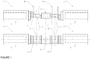
- a high power photovoltaic connector of the invention comprising two, preferably cylindrical, bimetallic connectors (1) having a copper end and an aluminium end (6), being connected to each other by their copper end preferably in the form of a shovel (2), making such a joint by means of tightening elements such as a system of nut (3) and screw (4), and to an aluminium conductor (5) by means of its cylindrical aluminium end (6), making such a joint by means of a tightening matrix or screws preferably furnished on the aluminium end (6).
- Said tightening matrix compressing the aluminium end (6) and the aluminium conductor (5) together due to deformation; being both the aluminium end (6) and the aluminium conductor (5) made of the same material with identical or very similar mechanical properties what the resulting tightening matrix achieves is to compress the aluminium end (6) of the bimetallic connectors ((1) once the aluminium conductor (5) has been inserted into it, so that the assembly is fixed due to the deformation of the aluminium.
- the object of the invention comprises that the copper blades (2) have such a shape that by assembling two bimetallic connectors (1) being aligned faced with each other in a mirror arrangement.
- each shovel (2) has a first smaller diameter hole (7) on which a fuse clip (8) and a second larger diameter hole (9) will be placed to join the two bimetallic connectors (1).
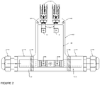
- a printed circuit board PCB (10) can be used to arrange the two bimetallic connectors (1) as well as the necessary fuse clips (8) as shown in Figure 2 .
- top fuse clips (8) are preferably attached to sections of copper plate or photovoltaic conductor (11) that will be connected to their respective fuse clip (8), using for this purpose a screw or similar element, and a photovoltaic connector (12) at its other end, with the polarity of this connector being suitable for the pole (positive or negative) on which the energy production system will be connected to.
- the system can be encapsulated in an insulating envelope (13), either registerable (an envelope formed by a bottom cover and a top cap that can be opened) or not (an injection of insulating polymer).
- the insulating envelope (13) may end in a thread (14) on each of the bimetallic connectors (1) which shall be extended by about 10 mm from the end of the copper zone (point A).
- the enclosure will have elements (17) such as holes, which allow it to be directly attached to the support structure of the photovoltaic system.
- each bimetallic connectors (1) is connected to a fuse clip (8) which is in turn attached to a PCB (10) comprising at its opposite end another fuse clip (8) from which a copper plate or photovoltaic conductor (11) configured to be connected to a photovoltaic connector (12).
- each bimetallic connectors (1) is connected to the fuse clip (8) by means of a copper plate or a photovoltaic conductor (11).
- a copper plate or photovoltaic conductor (11) may be acting as interconnector to the fuse clip (8) which may be attached to a PCB (10) that will have at its opposite end another fuse clip (8) from which another copper plate or photovoltaic conductor (11) will be born that will connect to the photovoltaic connector (12).
- the final result thus formed will be, identical to the previous case, encapsulated by an insulating envelope (13), registerable or not, which may end in a thread (14) on each of the bimetallic connectors (1) in order to assemble the respective cylinder protector (15) and cable gland (16) providing protection and insulation.
- the enclosure will have elements (17) such as holes, which allow direct attachment to a support structure of the photovoltaic system itself.
- the fuses and clips (8) required for assembly may not be part of the system, being external elements.
- the proposed system is simplified, with only connectors (1 or 18 depending on the configuration sought), copper plates or photovoltaic cable (11) directly connected to connectors (1) and photovoltaic connectors (12), insulating envelope (13) recordable or not including their fasteners (17), with their respective threaded ends (14), cylindrical guards (15) and cable glands (16).
- the system would look like the one represented in figure 4 .
Landscapes
- Photovoltaic Devices (AREA)
- Cable Accessories (AREA)
Priority Applications (4)
| Application Number | Priority Date | Filing Date | Title |
|---|---|---|---|
| EP21382110.1A EP4044375A1 (fr) | 2021-02-11 | 2021-02-11 | Connecteur photovoltaïque haute puissance |
| AU2022220819A AU2022220819A1 (en) | 2021-02-11 | 2022-02-11 | High power photovoltaic connector |
| PCT/EP2022/053349 WO2022171787A1 (fr) | 2021-02-11 | 2022-02-11 | Connecteur photovoltaïque haute puissance |
| US18/276,867 US20240128925A1 (en) | 2021-02-11 | 2022-02-11 | High power photovoltaic connector |
Applications Claiming Priority (1)
| Application Number | Priority Date | Filing Date | Title |
|---|---|---|---|
| EP21382110.1A EP4044375A1 (fr) | 2021-02-11 | 2021-02-11 | Connecteur photovoltaïque haute puissance |
Publications (1)
| Publication Number | Publication Date |
|---|---|
| EP4044375A1 true EP4044375A1 (fr) | 2022-08-17 |
Family
ID=74732840
Family Applications (1)
| Application Number | Title | Priority Date | Filing Date |
|---|---|---|---|
| EP21382110.1A Withdrawn EP4044375A1 (fr) | 2021-02-11 | 2021-02-11 | Connecteur photovoltaïque haute puissance |
Country Status (4)
| Country | Link |
|---|---|
| US (1) | US20240128925A1 (fr) |
| EP (1) | EP4044375A1 (fr) |
| AU (1) | AU2022220819A1 (fr) |
| WO (1) | WO2022171787A1 (fr) |
Citations (6)
| Publication number | Priority date | Publication date | Assignee | Title |
|---|---|---|---|---|
| FR2573927A1 (fr) * | 1984-11-29 | 1986-05-30 | Auxiliaire Appar Electric | Procede de fabrication d'une cosse de raccordement pour extremite de cable electrique, et cosse de raccordement ainsi obtenue |
| US20080283111A1 (en) * | 2004-11-16 | 2008-11-20 | Sumitomo Wiring Systems, Ltd. | Solar Cell Module Connector |
| WO2013055866A1 (fr) * | 2011-10-14 | 2013-04-18 | Solarbridge Technologies, Inc. | Boîtier isolant électrique |
| WO2014198856A1 (fr) | 2013-06-14 | 2014-12-18 | Phoenix Contact Gmbh & Co. Kg | Module de câble pour onduleur modulaire d'un générateur photovoltaïque |
| US9391380B2 (en) | 2008-03-28 | 2016-07-12 | Sunedison, Inc. | Electrical cable harness and assembly for transmitting AC electrical power |
| US9685904B2 (en) | 2013-10-16 | 2017-06-20 | General Electric Company | Photovoltaic system with improved DC connections and method of making same |
-
2021
- 2021-02-11 EP EP21382110.1A patent/EP4044375A1/fr not_active Withdrawn
-
2022
- 2022-02-11 AU AU2022220819A patent/AU2022220819A1/en active Pending
- 2022-02-11 US US18/276,867 patent/US20240128925A1/en active Pending
- 2022-02-11 WO PCT/EP2022/053349 patent/WO2022171787A1/fr active Application Filing
Patent Citations (6)
| Publication number | Priority date | Publication date | Assignee | Title |
|---|---|---|---|---|
| FR2573927A1 (fr) * | 1984-11-29 | 1986-05-30 | Auxiliaire Appar Electric | Procede de fabrication d'une cosse de raccordement pour extremite de cable electrique, et cosse de raccordement ainsi obtenue |
| US20080283111A1 (en) * | 2004-11-16 | 2008-11-20 | Sumitomo Wiring Systems, Ltd. | Solar Cell Module Connector |
| US9391380B2 (en) | 2008-03-28 | 2016-07-12 | Sunedison, Inc. | Electrical cable harness and assembly for transmitting AC electrical power |
| WO2013055866A1 (fr) * | 2011-10-14 | 2013-04-18 | Solarbridge Technologies, Inc. | Boîtier isolant électrique |
| WO2014198856A1 (fr) | 2013-06-14 | 2014-12-18 | Phoenix Contact Gmbh & Co. Kg | Module de câble pour onduleur modulaire d'un générateur photovoltaïque |
| US9685904B2 (en) | 2013-10-16 | 2017-06-20 | General Electric Company | Photovoltaic system with improved DC connections and method of making same |
Also Published As
| Publication number | Publication date |
|---|---|
| US20240128925A1 (en) | 2024-04-18 |
| AU2022220819A1 (en) | 2023-08-31 |
| WO2022171787A1 (fr) | 2022-08-18 |
Similar Documents
| Publication | Publication Date | Title |
|---|---|---|
| EP2413382B1 (fr) | Système intégral de mise à la terre de module CA | |
| US7762832B2 (en) | Systems for providing electrical interconnection between solar modules | |
| US10812015B2 (en) | Micro-inverter assembly for use in a photovoltaic system and method of making same | |
| US6344612B1 (en) | Terminal box device, and a solar panel and terminal box device assembly | |
| US8723370B2 (en) | Photovoltaic string sub-combiner | |
| EP2837039B1 (fr) | Système de jonction à forme effilée à multiplexeur distribué | |
| KR20140040687A (ko) | 다이오드-포함 커넥터, 광기전 라미네이트 및 이를 사용한 광기전 조립체 | |
| US20160233822A1 (en) | Photovoltaic grounding system and method of making same | |
| KR20100031077A (ko) | 전기 버스웨이 플랜지 단부 스터브 | |
| CN116317926A (zh) | 通用光伏层压板 | |
| US9893678B2 (en) | Photovoltaic system with improved AC connections and method of making same | |
| EP4044375A1 (fr) | Connecteur photovoltaïque haute puissance | |
| US20150280439A1 (en) | Apparatus for grounding interconnected electrical components and assemblies | |
| JPH11135169A (ja) | 端子の取付方法およびそれに用いる端子連続体 | |
| CN105850033A (zh) | 光伏模块接线盒 | |
| JPH10174254A (ja) | 電気接続箱の電気接続構造 | |
| JP2004119187A (ja) | バッテリ構成方法 | |
| JP2014225614A (ja) | 太陽電池接続箱 | |
| CN216056928U (zh) | 光伏组件 | |
| WO2023243640A1 (fr) | Unité de câble | |
| CN218633363U (zh) | 一种户用储能电池柜 | |
| KR20180080815A (ko) | 부스덕트 접속부 | |
| KR101756729B1 (ko) | 케이블 단자대용 풀림방지너트 | |
| CN117411328A (zh) | 功率变换器、熔断器及储能系统 | |
| KR20230029483A (ko) | 케이블 분리형 bipv 정션박스 |
Legal Events
| Date | Code | Title | Description |
|---|---|---|---|
| PUAI | Public reference made under article 153(3) epc to a published international application that has entered the european phase |
Free format text: ORIGINAL CODE: 0009012 |
|
| STAA | Information on the status of an ep patent application or granted ep patent |
Free format text: STATUS: THE APPLICATION HAS BEEN PUBLISHED |
|
| AK | Designated contracting states |
Kind code of ref document: A1 Designated state(s): AL AT BE BG CH CY CZ DE DK EE ES FI FR GB GR HR HU IE IS IT LI LT LU LV MC MK MT NL NO PL PT RO RS SE SI SK SM TR |
|
| STAA | Information on the status of an ep patent application or granted ep patent |
Free format text: STATUS: THE APPLICATION IS DEEMED TO BE WITHDRAWN |
|
| 18D | Application deemed to be withdrawn |
Effective date: 20230218 |