EP4044037A1 - Acquiring and encrypting a debug log for a native application in an image processing device and transferring it to a remote system - Google Patents
Acquiring and encrypting a debug log for a native application in an image processing device and transferring it to a remote system Download PDFInfo
- Publication number
- EP4044037A1 EP4044037A1 EP22156084.0A EP22156084A EP4044037A1 EP 4044037 A1 EP4044037 A1 EP 4044037A1 EP 22156084 A EP22156084 A EP 22156084A EP 4044037 A1 EP4044037 A1 EP 4044037A1
- Authority
- EP
- European Patent Office
- Prior art keywords
- built
- application
- encryption key
- debug log
- image processing
- Prior art date
- Legal status (The legal status is an assumption and is not a legal conclusion. Google has not performed a legal analysis and makes no representation as to the accuracy of the status listed.)
- Pending
Links
Images



Classifications
-
- G—PHYSICS
- G06—COMPUTING OR CALCULATING; COUNTING
- G06F—ELECTRIC DIGITAL DATA PROCESSING
- G06F11/00—Error detection; Error correction; Monitoring
- G06F11/36—Prevention of errors by analysis, debugging or testing of software
- G06F11/362—Debugging of software
- G06F11/3636—Debugging of software by tracing the execution of the program
-
- G—PHYSICS
- G06—COMPUTING OR CALCULATING; COUNTING
- G06F—ELECTRIC DIGITAL DATA PROCESSING
- G06F21/00—Security arrangements for protecting computers, components thereof, programs or data against unauthorised activity
- G06F21/60—Protecting data
- G06F21/62—Protecting access to data via a platform, e.g. using keys or access control rules
- G06F21/6209—Protecting access to data via a platform, e.g. using keys or access control rules to a single file or object, e.g. in a secure envelope, encrypted and accessed using a key, or with access control rules appended to the object itself
-
- H—ELECTRICITY
- H04—ELECTRIC COMMUNICATION TECHNIQUE
- H04N—PICTORIAL COMMUNICATION, e.g. TELEVISION
- H04N1/00—Scanning, transmission or reproduction of documents or the like, e.g. facsimile transmission; Details thereof
- H04N1/00912—Arrangements for controlling a still picture apparatus or components thereof not otherwise provided for
- H04N1/00938—Software related arrangements, e.g. loading applications
-
- G—PHYSICS
- G06—COMPUTING OR CALCULATING; COUNTING
- G06F—ELECTRIC DIGITAL DATA PROCESSING
- G06F11/00—Error detection; Error correction; Monitoring
- G06F11/36—Prevention of errors by analysis, debugging or testing of software
- G06F11/362—Debugging of software
-
- G—PHYSICS
- G06—COMPUTING OR CALCULATING; COUNTING
- G06F—ELECTRIC DIGITAL DATA PROCESSING
- G06F11/00—Error detection; Error correction; Monitoring
- G06F11/36—Prevention of errors by analysis, debugging or testing of software
- G06F11/3668—Testing of software
- G06F11/3672—Test management
- G06F11/3692—Test management for test results analysis
-
- G—PHYSICS
- G06—COMPUTING OR CALCULATING; COUNTING
- G06F—ELECTRIC DIGITAL DATA PROCESSING
- G06F11/00—Error detection; Error correction; Monitoring
- G06F11/36—Prevention of errors by analysis, debugging or testing of software
- G06F11/3698—Environments for analysis, debugging or testing of software
-
- G—PHYSICS
- G06—COMPUTING OR CALCULATING; COUNTING
- G06F—ELECTRIC DIGITAL DATA PROCESSING
- G06F21/00—Security arrangements for protecting computers, components thereof, programs or data against unauthorised activity
- G06F21/60—Protecting data
- G06F21/602—Providing cryptographic facilities or services
-
- H—ELECTRICITY
- H04—ELECTRIC COMMUNICATION TECHNIQUE
- H04N—PICTORIAL COMMUNICATION, e.g. TELEVISION
- H04N1/00—Scanning, transmission or reproduction of documents or the like, e.g. facsimile transmission; Details thereof
- H04N1/00127—Connection or combination of a still picture apparatus with another apparatus, e.g. for storage, processing or transmission of still picture signals or of information associated with a still picture
- H04N1/00204—Connection or combination of a still picture apparatus with another apparatus, e.g. for storage, processing or transmission of still picture signals or of information associated with a still picture with a digital computer or a digital computer system, e.g. an internet server
- H04N1/00206—Transmitting or receiving computer data via an image communication device, e.g. a facsimile transceiver
-
- H—ELECTRICITY
- H04—ELECTRIC COMMUNICATION TECHNIQUE
- H04N—PICTORIAL COMMUNICATION, e.g. TELEVISION
- H04N1/00—Scanning, transmission or reproduction of documents or the like, e.g. facsimile transmission; Details thereof
- H04N1/32—Circuits or arrangements for control or supervision between transmitter and receiver or between image input and image output device, e.g. between a still-image camera and its memory or between a still-image camera and a printer device
- H04N1/32101—Display, printing, storage or transmission of additional information, e.g. ID code, date and time or title
- H04N1/32144—Display, printing, storage or transmission of additional information, e.g. ID code, date and time or title embedded in the image data, i.e. enclosed or integrated in the image, e.g. watermark, super-imposed logo or stamp
- H04N1/32149—Methods relating to embedding, encoding, decoding, detection or retrieval operations
- H04N1/32267—Methods relating to embedding, encoding, decoding, detection or retrieval operations combined with processing of the image
- H04N1/32272—Encryption or ciphering
-
- H—ELECTRICITY
- H04—ELECTRIC COMMUNICATION TECHNIQUE
- H04N—PICTORIAL COMMUNICATION, e.g. TELEVISION
- H04N1/00—Scanning, transmission or reproduction of documents or the like, e.g. facsimile transmission; Details thereof
- H04N1/32—Circuits or arrangements for control or supervision between transmitter and receiver or between image input and image output device, e.g. between a still-image camera and its memory or between a still-image camera and a printer device
- H04N1/32358—Circuits or arrangements for control or supervision between transmitter and receiver or between image input and image output device, e.g. between a still-image camera and its memory or between a still-image camera and a printer device using picture signal storage, e.g. at transmitter
-
- H—ELECTRICITY
- H04—ELECTRIC COMMUNICATION TECHNIQUE
- H04N—PICTORIAL COMMUNICATION, e.g. TELEVISION
- H04N2201/00—Indexing scheme relating to scanning, transmission or reproduction of documents or the like, and to details thereof
- H04N2201/32—Circuits or arrangements for control or supervision between transmitter and receiver or between image input and image output device, e.g. between a still-image camera and its memory or between a still-image camera and a printer device
- H04N2201/3201—Display, printing, storage or transmission of additional information, e.g. ID code, date and time or title
- H04N2201/328—Processing of the additional information
- H04N2201/3281—Encryption; Ciphering
-
- H—ELECTRICITY
- H04—ELECTRIC COMMUNICATION TECHNIQUE
- H04N—PICTORIAL COMMUNICATION, e.g. TELEVISION
- H04N2201/00—Indexing scheme relating to scanning, transmission or reproduction of documents or the like, and to details thereof
- H04N2201/32—Circuits or arrangements for control or supervision between transmitter and receiver or between image input and image output device, e.g. between a still-image camera and its memory or between a still-image camera and a printer device
- H04N2201/3201—Display, printing, storage or transmission of additional information, e.g. ID code, date and time or title
- H04N2201/328—Processing of the additional information
- H04N2201/3284—Processing of the additional information for error correction
Definitions
- Embodiments described herein relate generally to an image processing device, an image processing method, and a diagnostic system for the image processing device.
- the debug log obtained from the image processing device is not limited to the debug log of the built-in application in which the malfunction occurs, and also includes a debug log of controller software installed in the image processing device.
- the debug log is encrypted, the debug log of the built-in application in which the malfunction occurs cannot be extracted without decrypting all debug logs acquired from the image processing device. Therefore, a mechanism of collecting a debug log of a desired built-in application with a simple operation is demanded.
- One of the objects of the present invention is to improve prior art techniques and overcome at least some of the prior art problems as for instance above illustrated.
- an image processing device comprising a memory for storing an encryption key in correlation with a built-in application during installation of the built-in application; an encryption component for encrypting a debug log relating to the built-in application with the encryption key in correlation with the corresponding built-in application; and an output component for outputting the debug log encrypted by the encryption component.
- the output component transmits the debug log to a transmission destination set in advance.
- the image processing device further provides a reception component for receiving instruction of whether to set the encryption key if there is no the encryption key in correlation with the built-in application.
- the memory stores the encryption key uploaded from outside of the image processing device.
- the output component if an instruction not to set the encryption key is received by the reception component, the output component outputs the debug log relating to the built-in application without encryption.
- the built-in application comprises built-in application data record includes at least two of program data of the built-in application, metadata of the built-in application, the encryption key, a folder name of the debug log, an acquisition timing of the debug log, and a transmission destination of the debug log.
- the encryption key is a unique key set for each built-in application in order to encrypt the debug log of the built-in application.
- an image processing method comprising storing an encryption key in correlation with a built-in application during installation of the built-in application; encrypting a debug log relating to the built-in application with the encryption key in correlation with the corresponding built-in application; and outputting the encrypted debug log.
- the image processing method according to the second aspect of the invention further comprises if a malfunction of the built-in application occurs, switching an operation mode from a normal mode to a maintenance mode.
- the image processing method according to the second aspect of the invention further comprises transmitting the debug log to a transmission destination set in advance.
- the image processing method according to the second aspect of the invention further comprises a reception component for receiving instruction of whether to set the encryption key if there is no the encryption key in correlation with the built-in application.
- the image processing method according to the second aspect of the invention further comprises if an instruction to set the encryption key is received, storing the encryption key uploaded from outside of the image processing device.
- the image processing method according to the second aspect of the invention further comprises, wherein, if an instruction not to set the encryption key is received, outputting the debug log relating to the built-in application without encryption.
- a diagnostic system for an image processing device comprising a memory for storing an encryption key in correlation with a built-in application during installation of the built-in application; an encryption component for encrypting a debug log relating to the built-in application with the encryption key in correlation with the corresponding built-in application; and an output component for outputting the debug log encrypted by the encryption component.
- the output component transmits the debug log to a transmission destination set in advance.
- the diagnostic system further comprises a reception component for receiving instruction of whether to set the encryption key if there is no the encryption key in correlation with the built-in application.
- the memory stores the encryption key uploaded from outside of the image processing device.
- the output component outputs the debug log relating to the built-in application without encryption.
- the built-in application comprises built-in application data record includes at least two of program data of the built-in application, metadata of the built-in application, the encryption key, a folder name of the debug log, an acquisition timing of the debug log, and a transmission destination of the debug log.
- the encryption key is a unique key set for each built-in application in order to encrypt the debug log of the built-in application.
- An object to be achieved by embodiments is to provide an image processing device and an image processing method capable of collecting a debug log of a desired built-in application with a simple operation.
- an image processing device includes storage means, encryption means, and output means.
- the storage means stores an encryption key in correlation with a built-in application during installation of the built-in application.
- the encryption means encrypts a debug log relating to the built-in application with the encryption key in correlation with the corresponding built-in application.
- the output means outputs the debug log encrypted by the encryption means.
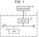
- FIG. 1 is a block diagram illustrating a schematic configuration of an image processing system 1.
- the image processing system 1 includes an MFP 10 and a router 20.
- the MFP 10 is an example of the image processing device.
- the router 20 is connected to a cloud server 30 via a dedicated communication network 3.
- the dedicated communication network 3 is typically a dedicated digital line, an Integrated Services Digital Network (ISDN) line, or the like.
- the router 20 is a network device that relays data communication between each device connected to a communication network 2 and the cloud server 30.
- the cloud server 30 is a server device for cloud computing.
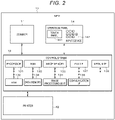
- FIG. 2 is a block diagram illustrating a schematic configuration of the MFP 10.
- the MFP 10 includes a scanner 11, a printer 12, a control system 13, and an operation panel 14.
- the scanner 11, the printer 12, and the operation panel 14 are connected to the control system 13.
- the scanner 11 is a device that optically reads an image of a document according to an operation instruction from the control system 13 and converts the image into image information.
- the scanner 11 outputs the image information of the read document to the control system 13.
- the printer 12 prints an image based on the image information supplied from the control system 13 on paper in various printing conditions designated from the control system 13.
- printers of various image forming methods can be applied.
- the printer 12 may be a printer in an electrophotographic method, and may be a printer in an inkjet method or a thermal transfer method.
- the control system 13 collectively controls an operation of each unit such as the scanner 11, the printer 12, and the operation panel 14. In addition, the control system 13 performs various processes such as image processing.
- the control system 13 includes a processor 131, a random-access memory (RAM) 132, a read-only memory (ROM) 133, a data memory 134, an image memory 135, an image processing unit 136, a facsimile (FAX) interface (I/F) 137, a communication interface (I/F) 138, and a medium interface (I/F) 139.
- the processor 131 performs processes such as calculation and control according to programs.
- the processor 131 is, for example, a central processing unit (CPU).
- the processor 131 realizes various processing functions by executing programs stored in the ROM 133 or the data memory 134.
- the RAM 132 is a volatile memory.
- the RAM 132 functions, for example, as a working memory.
- the ROM 133 is a non-volatile memory.
- the ROM 133 functions, for example, as a program memory.
- the data memory 134 stores control data, a control program, setting information, and the like.
- the data memory 134 is, for example, a rewritable non-volatile memory.
- the image memory 135 stores image information.
- the image processing unit 136 performs image processing with respect to image information.
- the FAX interface 137 is an interface for performing FAX communication.
- the communication interface 138 is an interface for performing data communication with an external device via a network such as the communication network 2.
- the medium interface 139 is an interface for performing data communication with a storage medium such as a memory card or a universal serial bus (USB) memory.
- the operation panel 14 is a user interface.
- the operation panel 14 includes a touch panel 141 and an input device 142.
- the touch panel 141 is obtained, for example, by stacking a display such as a liquid crystal display or an organic electro-luminescence (EL) display and a sensing device that detects touch input.
- the input device 142 is, for example, a button, keyboard, a keypad, or a touchpad.
- the MFP 10 includes a built-in application database 40 in the data memory 134.
- the built-in application is referred to as a built-in app.
- the built-in app database 40 is an assembly of built-in app data records 401 (see FIG. 3 ) generated for each MFP 10.
- FIG. 3 is a schematic diagram illustrating a main data structure of the built-in app data record 401.
- the built-in app data record 401 includes program data of the built-in app, metadata of the built-in app, an encryption key, a folder name of a debug log, an acquisition timing of the debug log, a transmission destination of the debug log, and the like.
- the built-in app is installed on the MFP 10 in the form of the package software.
- the package software includes program data of the built-in app, metadata of the built-in app, and an encryption key.
- the program data of the built-in app is data in which a program for executing the built-in app is written.
- the metadata of the built-in app is a built-in app ID, a name, and the vender information for generating the built-in app, and the like.
- the encryption key is a unique key set for each built-in app in order to encrypt the debug log of the built-in app.
- the folder name of the debug log is a name of a folder that is a storage destination for storing the debug log relating to the malfunction occurring during the execution of the built-in app.
- the folder of the debug log is generated for each built-in app if the package software is installed. After the package software is installed, a debug log setting screen 100 (see FIG. 4 ) is displayed on the touch panel 141.
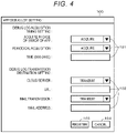
- FIG. 4 is a schematic diagram illustrating an example of the debug log setting screen 100.
- the debug log setting screen 100 includes an item field 101 that sets a timing for acquiring a debug log of the built-in app and an item field 102 that sets the transmission destination of the debug log. For example, whether to acquire the debug log in case of an error of the built-in app, whether to periodically acquire the debug log, or designated time in case where the debug log is to be periodically acquired are set in the item field 101. For example, whether to transmit the acquired debug log to the transmission destination and an address of the transmission destination in case of the transmission are set in the item field 102.
- the transmission destination is, for example, the cloud server 30, an administrator, a maintenance person.
- a uniform resource locator (URL) is input as the address of the transmission destination.
- the URL is a unique address allocated to the cloud server 30.
- the administrator or the maintenance person the mail address of the administrator or the maintenance person is input.
- the debug log setting screen 100 includes a registration button 103 for instructing setting confirmation of the item field 101 and the item field 102 and a cancel button 104 for instructing setting cancellation of the item field 101 and the item field 102.
- the content of the text data displayed in FIG. 4 is an example.
- the acquisition timing of the debug log and the transmission destination of the debug log are set on the debug log setting screen 100 in advance by the administrator. If the acquisition timing of the debug log and the transmission destination of the debug log are set, the setting is stored in the built-in app data record 401.
- the MFP 10 stores an app table 1341 (see FIG. 5 ) in the data memory 134.
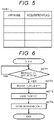
- FIG. 5 is a schematic diagram illustrating an example of the app table 1341.
- the app table 1341 is a data table configured in the app name, the acquisition flag, and the like.
- the app name is the name of the built-in app.
- the acquisition flag is set to "1" if the acquisition timing of the debug log is set on the debug log setting screen 100.
- the initial state of the acquisition flag is "0".
- the app table 1341 is not limited to the items of FIG. 5 .
- FIG. 6 is a flowchart illustrating the procedure of the information processes performed by the processor 131 of the MFP 10 if the administrator installs the built-in app in the MFP 10.
- the operation of the MFP 10 is described with reference to this flowchart.
- the procedure of the operations described below and the contents thereof are examples. The procedure and the contents are not limited as long as the same result can be obtained.
- the processor 131 of the MFP 10 waits for the instruction of the installation of the built-in app in ACT 1. If the installation of the built-in app is instructed, the processor 131 determines YES in ACT 1 and proceeds to ACT 2. The processor 131 installs the built-in app from the storage medium via the medium interface 139 in ACT 2.
- the processor 131 loads the package software in ACT 3.
- the package software the entire package software may be encrypted. In such a case, the entire package software is decrypted, and the electronic signature is confirmed.
- the processor 131 stores the program data of the built-in app, the metadata, and the encryption key included in the package software loaded in the process of ACT 3 in the built-in app data record 401 in ACT 4.
- the processor 131 stores the folder name of the folder of the debug log generated if the package software is installed in the built-in app data record 401. With the above, the processor 131 ends the information process of the procedure illustrated in the flowchart of FIG. 6 .
- FIG. 7 is a flowchart illustrating the procedure of the information process performed by the processor 131 of the MFP 10 if the user who uses the MFP 10 executes the built-in app.
- the operation of the MFP 10 is described with reference to this flowchart.
- the procedure of the operations and the contents thereof explained below are examples. The procedure and the contents are not limited as long as the same result can be obtained.
- the processor 131 of the MFP 10 waits for the instruction of executing the built-in app in ACT 11. If the execution of the built-in app is instructed, the processor 131 determines YES in ACT 11 and proceeds to ACT 12. The processor 131 executes the built-in app in ACT 12.
- the processor 131 confirms whether the acquisition flag of the app table 1341 is "1" in ACT 13. If the acquisition flag is not "1", that is, the acquisition flag is "0", the processor 131 determines NO in ACT 13 and proceeds to ACT 14.
- the processor 131 confirms whether built-in app ends in ACT 14. If the built-in app ends, the processor 131 determines YES in ACT 14, and the processor 131 ends the information processes of the procedure illustrated in the flowchart of FIG. 7 .
- the processor 131 determines YES in ACT 13 and proceeds to ACT 15.
- the processor 131 confirms whether the acquisition timing of the debug log is stored in the built-in app data record 401 in ACT 15. If the acquisition timing of the debug log is not stored, the processor 131 determines NO in ACT 15 and proceeds to ACT 17 described below.
- the processor 131 determines YES in ACT 15 and proceeds to ACT 16.
- the processor 131 extracts the folder of the folder name of the debug log stored in the built-in app data record 401 and stores the debug log of the built-in app in the folder in ACT 16.
- the processor 131 confirms whether the built-in app ends in ACT 17. If the built-in app does not end, the processor 131 determines NO in ACT 17 and returns to ACT 15. That is, the processor 131 repeatedly performs the processes of ACTS 15 to 17 until the built-in app ends.
- the processor 131 determines YES in ACT 17, and the processor 131 ends the information processes of the procedure illustrated in the flowchart of FIG. 7 .
- FIG. 8 is a flowchart illustrating the procedure of the information processes performed by the processor 131 of the MFP 10 if the administrator acquires the debug log of the built-in app.
- the operation of the MFP 10 is described with reference to this flowchart.
- the procedure of the operations and the contents thereof explained below are examples. The procedure and the contents are not limited as long as the same result can be obtained.
- the administrator switches the operation mode of the MFP 10 from the normal mode to the maintenance mode.
- the administrator designates the built-in app in which the malfunction occurs from the screen of the maintenance mode displayed on the touch panel 141 and inputs an acquisition button for acquiring the debug log of the corresponding built-in app.
- the processor 131 of the MFP 10 waits for the instruction of the acquisition of the debug log in ACT 21. If the acquisition of the debug log is instructed, the processor 131 determines YES in ACT 21 and proceeds to ACT 22.
- the processor 131 confirms whether the acquisition flag of the app table 1341 is "1" in ACT 22. If the acquisition flag is not "1", that is, the acquisition flag is "0", the processor 131 determines NO in ACT 22 and ends the information process of the procedure illustrated in the flowchart of FIG. 8 .
- the processor 131 determines YES in ACT 22 and proceeds to ACT 23.
- the processor 131 extracts the folder of the debug log of the corresponding built-in app and confirms whether the debug log is acquired in ACT 23. If the debug log is not acquired, the processor 131 determines NO in ACT 23 and ends the information process of the procedure illustrated in the flowchart of FIG. 8 .
- the processor 131 determines YES in ACT 23 and proceeds to ACT 24.
- the processor 131 acquires an encryption key corresponding to the corresponding built-in app stored in the built-in app data record 401 in ACT 24.
- the processor 131 encrypts the debug log by using the encryption key in ACT 25.
- the processor 131 stores the debug log encrypted in the RAM 132 in ACT 26.
- the processor 131 confirms whether the transmission destination of the debug log is stored in the built-in app data record 401 in ACT 27. If the transmission destination of the debug log is not stored, the processor 131 determines NO in ACT 27 and proceeds to ACT 28.
- the processor 131 outputs the encrypted debug log of the built-in app to the storage medium via the medium interface 139 in ACT 28. With the above, the processor 131 ends the information process of the procedure illustrated in the flowchart of FIG. 8 .
- the processor 131 determines YES in ACT 27 and proceeds to ACT 29.
- the processor 131 transmits the encrypted debug log of the built-in app to the stored transmission destination in ACT 29. With the above, the processor 131 ends the information process of the procedure illustrated in the flowchart of FIG. 8 .
- the processor 131 of the MFP 10 that is an example of the image processing device configures storage means by performing the processes of ACTS 1 to 4 of FIG. 6 . That is, the MFP 10 stores the encryption key in correlation with the built-in application if the built-in application is installed.
- the processor 131 of the MFP 10 configures encryption means by performing the processes of ACTS 21 to 25 of FIG. 8 . That is, the MFP 10 encrypts the debug log according to the built-in application with the encryption key in correlation with the corresponding built-in application.
- the processor 131 of the MFP 10 configures output means by performing the processes of ACTS 26 to 28 of FIG. 8 . That is, the MFP 10 outputs the debug log encrypted by the encryption means.
- the package software is loaded.
- the program data of the built-in app, the metadata of the built-in app, and the encryption key included in the package software are stored in the built-in app data record 401.
- the folder of the debug log generated during the installation is stored in the built-in app data record 401.
- the debug log is stored in the folder of the corresponding built-in app. Further, if the administrator acquires the debug log, the encryption key corresponding to the built-in app stored in the built-in app data record 401 is acquired. Also, the debug log encrypted by using the encryption key is stored in the RAM 132. If the transmission destination of the debug log is not stored in the built-in app data record 401, the encrypted debug log of the built-in app is automatically output to the storage medium. Therefore, the debug log of the desired built-in application can be collected by a simple operation.
- the debug log can be transmitted to the transmission destination such as the administrator and the cloud server 30 by a simple operation.
- the encryption key of the built-in app is described on the assumption of being included in the package software.
- FIG. 9 is a flowchart illustrating the procedure of the information process executed by the processor 131 of the MFP 10 if the administrator installs the built-in app in the MFP 10.
- the operation of the MFP 10 is described with reference to this flowchart.
- the procedure of the operations and the contents thereof explained below are examples. The procedure and the contents are not limited as long as the same result can be obtained.
- the processor 131 of the MFP 10 waits for the instruction of the installation of the built-in app in ACT 31. If the installation of the built-in app is instructed, the processor 131 determines YES in ACT 31 and proceeds to ACT 32. The processor 131 installs the built-in app from the storage medium via the medium interface 139 in ACT 32.
- the processor 131 loads the package software in ACT 33.
- the processor 131 confirms whether the encryption key is included in the package software loaded in the process of ACT 33 in ACT 34. If the encryption key is included, the processor 131 determines YES in ACT 34 and proceeds to ACT 35.
- the processor 131 stores the program data of the built-in app, the metadata, and the encryption key in the built-in app data record 401 in ACT 35.
- the processor 131 stores the folder name of the folder of the debug log generated during the installation of the package software in the built-in app data record 401. With the above, the processor 131 ends the information process of the procedure illustrated in the flowchart of FIG. 9 .
- the processor 131 determines NO in ACT 34 and proceeds to ACT 36.
- the processor 131 displays the encryption key selection screen 200 (see FIG. 10 ) for selecting whether to upload the encryption key to the touch panel 141 in ACT 36.
- FIG. 10 is a schematic diagram illustrating an example of the encryption key selection screen 200 according to the second embodiment.
- an encryption key selection screen 200 includes a built-in app name field 201 and a debug log acquisition check field 202.
- the built-in app installed in the MFP 10 in advance is displayed on the built-in app name field 201.
- An image of a button 203 that enables to select any one of "no encryption key” or "upload” is displayed on the debug log acquisition check field 202. If the output without encrypting the debug log of the built-in app is desired, the administrator inputs "no encryption key". If the upload of the encryption key from the cloud server 30 to the MFP 10 is desired, the administrator inputs "upload”.
- the encryption key selection screen 200 is not limited to the item of FIG. 10 .
- the processor 131 confirms whether the "upload” is input to the encryption key selection screen 200 in ACT 37. If the "upload” is not input, that is, "no encryption key” is input, the processor 131 determines NO in ACT 37 and proceeds to ACT 38.
- the processor 131 stores the program data and the metadata of the built-in app in the built-in app data record 401 in ACT 38.
- the processor 131 stores the folder name of the folder of the debug log generated during the installation of the package software in the built-in app data record 401. With the above, the processor 131 ends the information process of the procedure illustrated in the flowchart of FIG. 9 .
- the processor 131 determines YES in ACT 37 and proceeds to ACT 39.
- the processor 131 displays an encryption key setting screen 300 (see FIG. 11 ) in ACT 39.
- FIG. 11 is a schematic diagram illustrating an example of the encryption key setting screen 300 according to the second embodiment.
- the encryption key setting screen 300 includes an image of an upload button 301, an image of a cancel button 302, and a file path input field 303.
- the administrator inputs the file path to the file path input field 303 and inputs the upload button 301.
- the encryption key uploaded from the cloud server 30 is stored in the storage location designated by the file path.
- the cancel button 302 is input.
- the displayed content of the text data in FIG. 11 is an example.
- the processor 131 acquires the encryption key stored in the storage location designated in the file path in ACT 40.
- the processor 131 stores the program data and the metadata of the built-in app together with the encryption key acquired in the process of ACT 39 in the built-in app data record 401 in ACT 41.
- the processor 131 stores the folder name of the folder of the debug log generated during the installation of the package software in the built-in app data record 401. With the above, the processor 131 ends the information process of the procedure illustrated in the flowchart of FIG. 9 .
- the process of ACT 24 in FIG. 8 is different from that in the first embodiment. That is, the processor 131 confirms whether there is an encryption key in ACT 24. If there is an encryption key, the processor 131 determines YES in ACT 24 and proceeds to ACT 25. If there is not an encryption key, the processor 131 determines NO in ACT 24 and proceeds to ACT 27.
- the processor 131 of the MFP 10 that is an example of the image processing device performs the processes of ACTS 34, 36, and 37 of FIG. 9 to configure reception means. That is, if there is not an encryption key in correlation with the built-in application, the MFP 10 receives the instruction whether to set an encryption key. If the instruction to set the encryption key is received by the reception means, the storage means stores the encryption key uploaded from the outside. If the instruction not to set the encryption key is received by the reception means, the output means outputs the debug log relating to the built-in application without encryption.
- the image processing device is the MFP 10
- the image processing device is not limited to the MFP 10.
- the image processing device may be a copying machine or a printer.
- the built-in app database 40 may be a storage device built in the MFP 10 or may be a storage device attached outside the MFP 10.
- the debug log may be acquired if the usage rate of the processor 131 is higher than the reference value, and the debug log may be acquired if the usage amount of the ROM 133 or the data memory 134 is larger than the reference value.
- the transmission destination of the debug log is the cloud server 30, the administrator, the maintenance person, and the like is described.
- the debug log may be stored in the storage medium via the medium interface 139.
- the encryption key is uploaded from the cloud server 30 to the MFP 10 is described.
- an encryption key stored in a storage medium different from the storage medium for installing the built-in app may be uploaded to the MFP 10 via the medium interface 139.
Landscapes
- Engineering & Computer Science (AREA)
- Theoretical Computer Science (AREA)
- General Engineering & Computer Science (AREA)
- Computer Hardware Design (AREA)
- Physics & Mathematics (AREA)
- General Physics & Mathematics (AREA)
- Quality & Reliability (AREA)
- Multimedia (AREA)
- Signal Processing (AREA)
- Software Systems (AREA)
- General Health & Medical Sciences (AREA)
- Computer Security & Cryptography (AREA)
- Bioethics (AREA)
- Health & Medical Sciences (AREA)
- Computing Systems (AREA)
- Facsimiles In General (AREA)
- Accessory Devices And Overall Control Thereof (AREA)
- Debugging And Monitoring (AREA)
Abstract

Description
- This application is based upon and claims the benefit of priority from
Japanese Patent Application No. 2021-020516, filed on February 12, 2021 - Embodiments described herein relate generally to an image processing device, an image processing method, and a diagnostic system for the image processing device.
- In the related art, if malfunction occurs in a built-in application of an image processing device such as a digital multi-functional peripheral (MFP), an administrator, a maintenance person, or the like acquires a debug log according to the built-in application in which the malfunction occurs, from the image processing device and analyzes the debug log to find a cause of the malfunction. However, the debug log obtained from the image processing device is not limited to the debug log of the built-in application in which the malfunction occurs, and also includes a debug log of controller software installed in the image processing device. Further, since the debug log is encrypted, the debug log of the built-in application in which the malfunction occurs cannot be extracted without decrypting all debug logs acquired from the image processing device. Therefore, a mechanism of collecting a debug log of a desired built-in application with a simple operation is demanded.
- One of the objects of the present invention is to improve prior art techniques and overcome at least some of the prior art problems as for instance above illustrated.
- According to a first aspect of the present invention, it is provided an image processing device, comprising a memory for storing an encryption key in correlation with a built-in application during installation of the built-in application; an encryption component for encrypting a debug log relating to the built-in application with the encryption key in correlation with the corresponding built-in application; and an output component for outputting the debug log encrypted by the encryption component.
- Optionally, in the image processing device according to the first aspect of the present invention, wherein the output component transmits the debug log to a transmission destination set in advance.
- Optionally, the image processing device according to the first aspect of the present invention further provides a reception component for receiving instruction of whether to set the encryption key if there is no the encryption key in correlation with the built-in application.
- Optionally, in the image processing device according to the first aspect of the present invention, if an instruction to set the encryption key is received by the reception component, the memory stores the encryption key uploaded from outside of the image processing device.
- Optionally, in the image processing device according to the first aspect of the present invention, if an instruction not to set the encryption key is received by the reception component, the output component outputs the debug log relating to the built-in application without encryption.
- Optionally, in the image processing device according to the first aspect of the present invention, the built-in application comprises built-in application data record includes at least two of program data of the built-in application, metadata of the built-in application, the encryption key, a folder name of the debug log, an acquisition timing of the debug log, and a transmission destination of the debug log.
- Optionally, in the image processing device according to the first aspect of the present invention, the encryption key is a unique key set for each built-in application in order to encrypt the debug log of the built-in application.
- According to a second aspect of the invention, it is provided an image processing method, comprising storing an encryption key in correlation with a built-in application during installation of the built-in application; encrypting a debug log relating to the built-in application with the encryption key in correlation with the corresponding built-in application; and outputting the encrypted debug log.
- Optionally, the image processing method according to the second aspect of the invention further comprises if a malfunction of the built-in application occurs, switching an operation mode from a normal mode to a maintenance mode.
- Optionally, the image processing method according to the second aspect of the invention further comprises transmitting the debug log to a transmission destination set in advance.
- Optionally, the image processing method according to the second aspect of the invention further comprises a reception component for receiving instruction of whether to set the encryption key if there is no the encryption key in correlation with the built-in application.
- Optionally, the image processing method according to the second aspect of the invention further comprises if an instruction to set the encryption key is received, storing the encryption key uploaded from outside of the image processing device.
- Optionally, the image processing method according to the second aspect of the invention further comprises, wherein, if an instruction not to set the encryption key is received, outputting the debug log relating to the built-in application without encryption.
- According to a third aspect of the present invention, it is provided a diagnostic system for an image processing device, comprising a memory for storing an encryption key in correlation with a built-in application during installation of the built-in application; an encryption component for encrypting a debug log relating to the built-in application with the encryption key in correlation with the corresponding built-in application; and an output component for outputting the debug log encrypted by the encryption component.
- Optionally, in the diagnostic system according to the third aspect of the invention, the output component transmits the debug log to a transmission destination set in advance.
- Optionally, the diagnostic system according to the third aspect of the invention further comprises a reception component for receiving instruction of whether to set the encryption key if there is no the encryption key in correlation with the built-in application.
- Optionally, in the diagnostic system according to the third aspect of the invention, if an instruction to set the encryption key is received by the reception component, the memory stores the encryption key uploaded from outside of the image processing device.
- Optionally, in the diagnostic system according to the third aspect of the invention, if an instruction not to set the encryption key is received by the reception component, the output component outputs the debug log relating to the built-in application without encryption.
- Optionally, in the diagnostic system according to the third aspect of the invention, the built-in application comprises built-in application data record includes at least two of program data of the built-in application, metadata of the built-in application, the encryption key, a folder name of the debug log, an acquisition timing of the debug log, and a transmission destination of the debug log.
- Optionally, in the diagnostic system according to the third aspect of the invention, the encryption key is a unique key set for each built-in application in order to encrypt the debug log of the built-in application.
-
-
FIG. 1 is a schematic diagram illustrating a schematic configuration of an image processing system; -
FIG. 2 is a block diagram illustrating a main circuit configuration of an MFP; -
FIG. 3 is a schematic diagram illustrating a main data structure of a built-in app data record; -
FIG. 4 is a schematic diagram illustrating an example of a debug log setting screen; -
FIG. 5 is a schematic diagram illustrating an example of an app table; -
FIG. 6 is a flowchart illustrating a main control procedure of a processor of the MFP; -
FIG. 7 is a flowchart illustrating the main control procedure of the processor of the MFP; -
FIG. 8 is a flowchart illustrating the main control procedure of the processor of the MFP; -
FIG. 9 is a flowchart illustrating a main control procedure of a processor of an MFP according to a second embodiment; -
FIG. 10 is a schematic diagram illustrating an example of an encryption key selection screen; and -
FIG. 11 is a schematic diagram illustrating an example of the encryption key setting screen. - An object to be achieved by embodiments is to provide an image processing device and an image processing method capable of collecting a debug log of a desired built-in application with a simple operation.
- In general, according to one embodiment, an image processing device includes storage means, encryption means, and output means. The storage means stores an encryption key in correlation with a built-in application during installation of the built-in application. The encryption means encrypts a debug log relating to the built-in application with the encryption key in correlation with the corresponding built-in application. The output means outputs the debug log encrypted by the encryption means.
- Hereinafter, embodiments are described with reference to the drawings.
-
FIG. 1 is a block diagram illustrating a schematic configuration of animage processing system 1. Theimage processing system 1 includes anMFP 10 and arouter 20. TheMFP 10 is an example of the image processing device. Therouter 20 is connected to acloud server 30 via adedicated communication network 3. Thededicated communication network 3 is typically a dedicated digital line, an Integrated Services Digital Network (ISDN) line, or the like. Therouter 20 is a network device that relays data communication between each device connected to a communication network 2 and thecloud server 30. Thecloud server 30 is a server device for cloud computing. -
FIG. 2 is a block diagram illustrating a schematic configuration of theMFP 10. The MFP 10 includes ascanner 11, aprinter 12, acontrol system 13, and anoperation panel 14. Thescanner 11, theprinter 12, and theoperation panel 14 are connected to thecontrol system 13. - The
scanner 11 is a device that optically reads an image of a document according to an operation instruction from thecontrol system 13 and converts the image into image information. Thescanner 11 outputs the image information of the read document to thecontrol system 13. - The
printer 12 prints an image based on the image information supplied from thecontrol system 13 on paper in various printing conditions designated from thecontrol system 13. As theprinter 12, printers of various image forming methods can be applied. For example, theprinter 12 may be a printer in an electrophotographic method, and may be a printer in an inkjet method or a thermal transfer method. - The
control system 13 collectively controls an operation of each unit such as thescanner 11, theprinter 12, and theoperation panel 14. In addition, thecontrol system 13 performs various processes such as image processing. Thecontrol system 13 includes aprocessor 131, a random-access memory (RAM) 132, a read-only memory (ROM) 133, adata memory 134, animage memory 135, animage processing unit 136, a facsimile (FAX) interface (I/F) 137, a communication interface (I/F) 138, and a medium interface (I/F) 139. - The
processor 131 performs processes such as calculation and control according to programs. Theprocessor 131 is, for example, a central processing unit (CPU). Theprocessor 131 realizes various processing functions by executing programs stored in theROM 133 or thedata memory 134. TheRAM 132 is a volatile memory. TheRAM 132 functions, for example, as a working memory. TheROM 133 is a non-volatile memory. TheROM 133 functions, for example, as a program memory. - The
data memory 134 stores control data, a control program, setting information, and the like. Thedata memory 134 is, for example, a rewritable non-volatile memory. Theimage memory 135 stores image information. Theimage processing unit 136 performs image processing with respect to image information. - The
FAX interface 137 is an interface for performing FAX communication. Thecommunication interface 138 is an interface for performing data communication with an external device via a network such as the communication network 2. Themedium interface 139 is an interface for performing data communication with a storage medium such as a memory card or a universal serial bus (USB) memory. - The
operation panel 14 is a user interface. Theoperation panel 14 includes atouch panel 141 and aninput device 142. Thetouch panel 141 is obtained, for example, by stacking a display such as a liquid crystal display or an organic electro-luminescence (EL) display and a sensing device that detects touch input. Theinput device 142 is, for example, a button, keyboard, a keypad, or a touchpad. - The
MFP 10 includes a built-in application database 40 in thedata memory 134. Hereinafter, the built-in application is referred to as a built-in app. The built-in app database 40 is an assembly of built-in app data records 401 (seeFIG. 3 ) generated for eachMFP 10. -
FIG. 3 is a schematic diagram illustrating a main data structure of the built-inapp data record 401. As illustrated inFIG. 3 , the built-inapp data record 401 includes program data of the built-in app, metadata of the built-in app, an encryption key, a folder name of a debug log, an acquisition timing of the debug log, a transmission destination of the debug log, and the like. The built-in app is installed on theMFP 10 in the form of the package software. The package software includes program data of the built-in app, metadata of the built-in app, and an encryption key. The program data of the built-in app is data in which a program for executing the built-in app is written. The metadata of the built-in app is a built-in app ID, a name, and the vender information for generating the built-in app, and the like. The encryption key is a unique key set for each built-in app in order to encrypt the debug log of the built-in app. The folder name of the debug log is a name of a folder that is a storage destination for storing the debug log relating to the malfunction occurring during the execution of the built-in app. The folder of the debug log is generated for each built-in app if the package software is installed. After the package software is installed, a debug log setting screen 100 (seeFIG. 4 ) is displayed on thetouch panel 141. -
FIG. 4 is a schematic diagram illustrating an example of the debuglog setting screen 100. As illustrated inFIG. 4 , the debuglog setting screen 100 includes anitem field 101 that sets a timing for acquiring a debug log of the built-in app and anitem field 102 that sets the transmission destination of the debug log. For example, whether to acquire the debug log in case of an error of the built-in app, whether to periodically acquire the debug log, or designated time in case where the debug log is to be periodically acquired are set in theitem field 101. For example, whether to transmit the acquired debug log to the transmission destination and an address of the transmission destination in case of the transmission are set in theitem field 102. The transmission destination is, for example, thecloud server 30, an administrator, a maintenance person. In case of thecloud server 30, a uniform resource locator (URL) is input as the address of the transmission destination. The URL is a unique address allocated to thecloud server 30. In case of the administrator or the maintenance person, the mail address of the administrator or the maintenance person is input. If the acquisition of the debug log is set for theitem field 101, theitem field 102 may be enabled. In addition, the debuglog setting screen 100 includes aregistration button 103 for instructing setting confirmation of theitem field 101 and theitem field 102 and a cancelbutton 104 for instructing setting cancellation of theitem field 101 and theitem field 102. The content of the text data displayed inFIG. 4 is an example. - The description refers back to
FIG. 3 . - The acquisition timing of the debug log and the transmission destination of the debug log are set on the debug
log setting screen 100 in advance by the administrator. If the acquisition timing of the debug log and the transmission destination of the debug log are set, the setting is stored in the built-inapp data record 401. - The description refers back to
FIG. 2 . - The
MFP 10 stores an app table 1341 (seeFIG. 5 ) in thedata memory 134. -
FIG. 5 is a schematic diagram illustrating an example of the app table 1341. As illustrated inFIG. 5 , the app table 1341 is a data table configured in the app name, the acquisition flag, and the like. The app name is the name of the built-in app. The acquisition flag is set to "1" if the acquisition timing of the debug log is set on the debuglog setting screen 100. The initial state of the acquisition flag is "0". The app table 1341 is not limited to the items ofFIG. 5 . -
FIG. 6 is a flowchart illustrating the procedure of the information processes performed by theprocessor 131 of theMFP 10 if the administrator installs the built-in app in theMFP 10. Hereinafter, the operation of theMFP 10 is described with reference to this flowchart. The procedure of the operations described below and the contents thereof are examples. The procedure and the contents are not limited as long as the same result can be obtained. - The
processor 131 of theMFP 10 waits for the instruction of the installation of the built-in app inACT 1. If the installation of the built-in app is instructed, theprocessor 131 determines YES inACT 1 and proceeds to ACT 2. Theprocessor 131 installs the built-in app from the storage medium via themedium interface 139 in ACT 2. - The
processor 131 loads the package software inACT 3. As the package software, the entire package software may be encrypted. In such a case, the entire package software is decrypted, and the electronic signature is confirmed. - The
processor 131 stores the program data of the built-in app, the metadata, and the encryption key included in the package software loaded in the process ofACT 3 in the built-inapp data record 401 in ACT 4. Theprocessor 131 stores the folder name of the folder of the debug log generated if the package software is installed in the built-inapp data record 401. With the above, theprocessor 131 ends the information process of the procedure illustrated in the flowchart ofFIG. 6 . -
FIG. 7 is a flowchart illustrating the procedure of the information process performed by theprocessor 131 of theMFP 10 if the user who uses theMFP 10 executes the built-in app. Hereinafter, the operation of theMFP 10 is described with reference to this flowchart. The procedure of the operations and the contents thereof explained below are examples. The procedure and the contents are not limited as long as the same result can be obtained. - The
processor 131 of theMFP 10 waits for the instruction of executing the built-in app inACT 11. If the execution of the built-in app is instructed, theprocessor 131 determines YES inACT 11 and proceeds toACT 12. Theprocessor 131 executes the built-in app inACT 12. - The
processor 131 confirms whether the acquisition flag of the app table 1341 is "1" inACT 13. If the acquisition flag is not "1", that is, the acquisition flag is "0", theprocessor 131 determines NO inACT 13 and proceeds toACT 14. - The
processor 131 confirms whether built-in app ends inACT 14. If the built-in app ends, theprocessor 131 determines YES inACT 14, and theprocessor 131 ends the information processes of the procedure illustrated in the flowchart ofFIG. 7 . - If the acquisition flag of the app table 1341 is "1", the
processor 131 determines YES inACT 13 and proceeds to ACT 15. Theprocessor 131 confirms whether the acquisition timing of the debug log is stored in the built-inapp data record 401 in ACT 15. If the acquisition timing of the debug log is not stored, theprocessor 131 determines NO in ACT 15 and proceeds to ACT 17 described below. - If the acquisition timing of the debug log is stored, the
processor 131 determines YES in ACT 15 and proceeds to ACT 16. Theprocessor 131 extracts the folder of the folder name of the debug log stored in the built-inapp data record 401 and stores the debug log of the built-in app in the folder in ACT 16. - The
processor 131 confirms whether the built-in app ends in ACT 17. If the built-in app does not end, theprocessor 131 determines NO in ACT 17 and returns to ACT 15. That is, theprocessor 131 repeatedly performs the processes of ACTS 15 to 17 until the built-in app ends. - If the built-in app ends, the
processor 131 determines YES in ACT 17, and theprocessor 131 ends the information processes of the procedure illustrated in the flowchart ofFIG. 7 . -
FIG. 8 is a flowchart illustrating the procedure of the information processes performed by theprocessor 131 of theMFP 10 if the administrator acquires the debug log of the built-in app. Hereinafter, the operation of theMFP 10 is described with reference to this flowchart. The procedure of the operations and the contents thereof explained below are examples. The procedure and the contents are not limited as long as the same result can be obtained. - If the malfunction of the built-in app occurs, the administrator switches the operation mode of the
MFP 10 from the normal mode to the maintenance mode. The administrator designates the built-in app in which the malfunction occurs from the screen of the maintenance mode displayed on thetouch panel 141 and inputs an acquisition button for acquiring the debug log of the corresponding built-in app. - That is, the
processor 131 of theMFP 10 waits for the instruction of the acquisition of the debug log in ACT 21. If the acquisition of the debug log is instructed, theprocessor 131 determines YES in ACT 21 and proceeds to ACT 22. - The
processor 131 confirms whether the acquisition flag of the app table 1341 is "1" in ACT 22. If the acquisition flag is not "1", that is, the acquisition flag is "0", theprocessor 131 determines NO in ACT 22 and ends the information process of the procedure illustrated in the flowchart ofFIG. 8 . - If the acquisition flag of the app table 1341 is "1", the
processor 131 determines YES in ACT 22 and proceeds to ACT 23. Theprocessor 131 extracts the folder of the debug log of the corresponding built-in app and confirms whether the debug log is acquired in ACT 23. If the debug log is not acquired, theprocessor 131 determines NO in ACT 23 and ends the information process of the procedure illustrated in the flowchart ofFIG. 8 . - If the debug log is acquired, the
processor 131 determines YES in ACT 23 and proceeds to ACT 24. Theprocessor 131 acquires an encryption key corresponding to the corresponding built-in app stored in the built-inapp data record 401 in ACT 24. Theprocessor 131 encrypts the debug log by using the encryption key in ACT 25. Theprocessor 131 stores the debug log encrypted in theRAM 132 in ACT 26. - The
processor 131 confirms whether the transmission destination of the debug log is stored in the built-inapp data record 401 in ACT 27. If the transmission destination of the debug log is not stored, theprocessor 131 determines NO in ACT 27 and proceeds to ACT 28. - The
processor 131 outputs the encrypted debug log of the built-in app to the storage medium via themedium interface 139 in ACT 28. With the above, theprocessor 131 ends the information process of the procedure illustrated in the flowchart ofFIG. 8 . - If the transmission destination of the debug log is stored, the
processor 131 determines YES in ACT 27 and proceeds to ACT 29. Theprocessor 131 transmits the encrypted debug log of the built-in app to the stored transmission destination in ACT 29. With the above, theprocessor 131 ends the information process of the procedure illustrated in the flowchart ofFIG. 8 . - As clearly described above, the
processor 131 of theMFP 10 that is an example of the image processing device configures storage means by performing the processes ofACTS 1 to 4 ofFIG. 6 . That is, theMFP 10 stores the encryption key in correlation with the built-in application if the built-in application is installed. - The
processor 131 of theMFP 10 configures encryption means by performing the processes of ACTS 21 to 25 ofFIG. 8 . That is, theMFP 10 encrypts the debug log according to the built-in application with the encryption key in correlation with the corresponding built-in application. - The
processor 131 of theMFP 10 configures output means by performing the processes of ACTS 26 to 28 ofFIG. 8 . That is, theMFP 10 outputs the debug log encrypted by the encryption means. - In this manner, according to the present embodiment, if the administrator instructs the
MFP 10 to install the built-in app, the package software is loaded. The program data of the built-in app, the metadata of the built-in app, and the encryption key included in the package software are stored in the built-inapp data record 401. In addition, the folder of the debug log generated during the installation is stored in the built-inapp data record 401. After the installation, the acquisition timing of the debug log and the transmission destination of the debug log are set in advance by the administrator on the debuglog setting screen 100. Also, if the user instructs the execution of the built-in app, if the acquisition flag of the app table 1341 is "1", and the acquisition timing of the debug log is stored in the built-inapp data record 401, the debug log is stored in the folder of the corresponding built-in app. Further, if the administrator acquires the debug log, the encryption key corresponding to the built-in app stored in the built-inapp data record 401 is acquired. Also, the debug log encrypted by using the encryption key is stored in theRAM 132. If the transmission destination of the debug log is not stored in the built-inapp data record 401, the encrypted debug log of the built-in app is automatically output to the storage medium. Therefore, the debug log of the desired built-in application can be collected by a simple operation. - If the transmission destination of the debug log is stored in the built-in
app data record 401, the encrypted debug log of the built-in app is transmitted to the transmission destination. Therefore, the debug log can be transmitted to the transmission destination such as the administrator and thecloud server 30 by a simple operation. - Subsequently, a second embodiment is described.
- According to the first embodiment, the encryption key of the built-in app is described on the assumption of being included in the package software.
- In the second embodiment, a case where the encryption key is not included in the package software is assumed. In the drawings relating to the second embodiment and the description thereof below, the same elements as those in the first embodiment are designated by the same reference numerals . Therefore, the description of the same elements may be omitted.
-
FIG. 9 is a flowchart illustrating the procedure of the information process executed by theprocessor 131 of theMFP 10 if the administrator installs the built-in app in theMFP 10. Hereinafter, the operation of theMFP 10 is described with reference to this flowchart. The procedure of the operations and the contents thereof explained below are examples. The procedure and the contents are not limited as long as the same result can be obtained. - The
processor 131 of theMFP 10 waits for the instruction of the installation of the built-in app in ACT 31. If the installation of the built-in app is instructed, theprocessor 131 determines YES in ACT 31 and proceeds to ACT 32. Theprocessor 131 installs the built-in app from the storage medium via themedium interface 139 in ACT 32. - The
processor 131 loads the package software in ACT 33. Theprocessor 131 confirms whether the encryption key is included in the package software loaded in the process of ACT 33 in ACT 34. If the encryption key is included, theprocessor 131 determines YES in ACT 34 and proceeds to ACT 35. Theprocessor 131 stores the program data of the built-in app, the metadata, and the encryption key in the built-inapp data record 401 in ACT 35. Theprocessor 131 stores the folder name of the folder of the debug log generated during the installation of the package software in the built-inapp data record 401. With the above, theprocessor 131 ends the information process of the procedure illustrated in the flowchart ofFIG. 9 . - If the encryption key is not included, the
processor 131 determines NO in ACT 34 and proceeds to ACT 36. Theprocessor 131 displays the encryption key selection screen 200 (seeFIG. 10 ) for selecting whether to upload the encryption key to thetouch panel 141 in ACT 36. -
FIG. 10 is a schematic diagram illustrating an example of the encryptionkey selection screen 200 according to the second embodiment. As illustrated inFIG. 10 , an encryptionkey selection screen 200 includes a built-inapp name field 201 and a debug logacquisition check field 202. The built-in app installed in theMFP 10 in advance is displayed on the built-inapp name field 201. An image of abutton 203 that enables to select any one of "no encryption key" or "upload" is displayed on the debug logacquisition check field 202. If the output without encrypting the debug log of the built-in app is desired, the administrator inputs "no encryption key". If the upload of the encryption key from thecloud server 30 to theMFP 10 is desired, the administrator inputs "upload". The encryptionkey selection screen 200 is not limited to the item ofFIG. 10 . - The description refers back to
FIG. 9 . - The
processor 131 confirms whether the "upload" is input to the encryptionkey selection screen 200 in ACT 37. If the "upload" is not input, that is, "no encryption key" is input, theprocessor 131 determines NO in ACT 37 and proceeds to ACT 38. Theprocessor 131 stores the program data and the metadata of the built-in app in the built-inapp data record 401 in ACT 38. Theprocessor 131 stores the folder name of the folder of the debug log generated during the installation of the package software in the built-inapp data record 401. With the above, theprocessor 131 ends the information process of the procedure illustrated in the flowchart ofFIG. 9 . - If "upload" is input, the
processor 131 determines YES in ACT 37 and proceeds to ACT 39. Theprocessor 131 displays an encryption key setting screen 300 (seeFIG. 11 ) in ACT 39. -
FIG. 11 is a schematic diagram illustrating an example of the encryptionkey setting screen 300 according to the second embodiment. As illustrated inFIG. 11 , the encryptionkey setting screen 300 includes an image of an uploadbutton 301, an image of a cancelbutton 302, and a filepath input field 303. The administrator inputs the file path to the filepath input field 303 and inputs the uploadbutton 301. However, the encryption key uploaded from thecloud server 30 is stored in the storage location designated by the file path. In case of cancelling the uploading of the file according to the encryption key, the cancelbutton 302 is input. The displayed content of the text data inFIG. 11 is an example. - The description refers back to
FIG. 9 . - The
processor 131 acquires the encryption key stored in the storage location designated in the file path in ACT 40. Theprocessor 131 stores the program data and the metadata of the built-in app together with the encryption key acquired in the process of ACT 39 in the built-inapp data record 401 in ACT 41. Theprocessor 131 stores the folder name of the folder of the debug log generated during the installation of the package software in the built-inapp data record 401. With the above, theprocessor 131 ends the information process of the procedure illustrated in the flowchart ofFIG. 9 . - In the second embodiment, the process of ACT 24 in
FIG. 8 is different from that in the first embodiment. That is, theprocessor 131 confirms whether there is an encryption key in ACT 24. If there is an encryption key, theprocessor 131 determines YES in ACT 24 and proceeds to ACT 25. If there is not an encryption key, theprocessor 131 determines NO in ACT 24 and proceeds to ACT 27. - As clearly described above, the
processor 131 of theMFP 10 that is an example of the image processing device performs the processes of ACTS 34, 36, and 37 ofFIG. 9 to configure reception means. That is, if there is not an encryption key in correlation with the built-in application, theMFP 10 receives the instruction whether to set an encryption key. If the instruction to set the encryption key is received by the reception means, the storage means stores the encryption key uploaded from the outside. If the instruction not to set the encryption key is received by the reception means, the output means outputs the debug log relating to the built-in application without encryption. - In this manner, in the second embodiment, a case where the encryption key is not included in the package software is assumed. An image of the
button 203 that enables to select any one of "no encryption key" or "upload" is displayed on the encryptionkey selection screen 200. Therefore, the administrator can select whether to set the encryption key and then acquire the debug log of the built-in app. - In the above, the embodiments of the image processing device and the image processing method are described, but the corresponding embodiment is not limited thereto.
- In the above embodiments, a case where the image processing device is the
MFP 10 is exemplified. The image processing device is not limited to theMFP 10. For example, the image processing device may be a copying machine or a printer. - In the above embodiments, a case where the
MFP 10 includes the built-in app database 40 is described. The built-in app database 40 may be a storage device built in theMFP 10 or may be a storage device attached outside theMFP 10. - In the above embodiments, whether to acquire the debug log in case of an error of the built-in app, whether to periodically acquire a debug log, and designation time in case of periodically acquiring the debug log are set in the
item field 101 for setting the timing of acquiring the debug log of the built-in app are described. For example, with respect to the timing, the debug log may be acquired if the usage rate of theprocessor 131 is higher than the reference value, and the debug log may be acquired if the usage amount of theROM 133 or thedata memory 134 is larger than the reference value. - According to the embodiment, a case where the transmission destination of the debug log is the
cloud server 30, the administrator, the maintenance person, and the like is described. For example, the debug log may be stored in the storage medium via themedium interface 139. - According to the second embodiment, a case where the encryption key is uploaded from the
cloud server 30 to theMFP 10 is described. For example, an encryption key stored in a storage medium different from the storage medium for installing the built-in app may be uploaded to theMFP 10 via themedium interface 139. - While certain embodiments have been described, these embodiments have been presented by way of example only, and are not intended to limit the scope of the inventions. Indeed, the novel embodiments described herein may be embodied in a variety of other forms; furthermore, various omissions, substitutions and changes in the form of the embodiments described herein may be made without departing from the scope of the inventions as defined by the appended claims. The accompanying claims and their equivalents are intended to cover such forms or modifications as would fall within the scope a of the inventions.
Claims (15)
- An image processing device, comprising:a memory for storing an encryption key in correlation with a built-in application during installation of the built-in application;an encryption component for encrypting a debug log relating to the built-in application with the encryption key in correlation with the corresponding built-in application; andan output component for outputting the debug log encrypted by the encryption component.
- The image processing device according to claim 1, wherein the output component transmits the debug log to a transmission destination set in advance.
- The image processing device according to claim 1 or 2, further comprising:
a reception component for receiving instruction of whether to set the encryption key if there is no the encryption key in correlation with the built-in application. - The image processing device according to claim 3, wherein, if an instruction to set the encryption key is received by the reception component, the memory stores the encryption key uploaded from outside of the image processing device.
- The image processing device according to claim 3 or 4,
wherein, if an instruction not to set the encryption key is received by the reception component, the output component outputs the debug log relating to the built-in application without encryption. - The image processing device according to any of claims 1 to 5,
wherein the built-in application comprises built-in application data record includes at least two of program data of the built-in application, metadata of the built-in application, the encryption key, a folder name of the debug log, an acquisition timing of the debug log, and a transmission destination of the debug log. - The image processing device according to any of claims 1 to 6,
wherein the encryption key is a unique key set for each built-in application in order to encrypt the debug log of the built-in application. - An image processing method, comprising:storing an encryption key in correlation with a built-in application during installation of the built-in application;encrypting a debug log relating to the built-in application with the encryption key in correlation with the corresponding built-in application; andoutputting the encrypted debug log.
- The image processing method according to claim 8, further comprising:
if a malfunction of the built-in application occurs, switching an operation mode from a normal mode to a maintenance mode. - The image processing method according to claim 8 or 9, further comprising:
transmitting the debug log to a transmission destination set in advance. - The image processing method according to any of claims 8 to 10, further comprising:
a reception component for receiving instruction of whether to set the encryption key if there is no the encryption key in correlation with the built-in application. - The image processing method according to claim 11, further comprising:
if an instruction to set the encryption key is received, storing the encryption key uploaded from outside of the image processing device. - The image processing method according to claim 11 or 12, further comprising:
wherein, if an instruction not to set the encryption key is received, outputting the debug log relating to the built-in application without encryption. - A diagnostic system for an image processing device, comprising:a memory for storing an encryption key in correlation with a built-in application during installation of the built-in application;an encryption component for encrypting a debug log relating to the built-in application with the encryption key in correlation with the corresponding built-in application; andan output component for outputting the debug log encrypted by the encryption component.
- The diagnostic system according to claim 14,
wherein the output component transmits the debug log to a transmission destination set in advance.
Applications Claiming Priority (1)
| Application Number | Priority Date | Filing Date | Title |
|---|---|---|---|
| JP2021020516A JP2022123293A (en) | 2021-02-12 | 2021-02-12 | Image processing apparatus and image processing method |
Publications (1)
| Publication Number | Publication Date |
|---|---|
| EP4044037A1 true EP4044037A1 (en) | 2022-08-17 |
Family
ID=80682852
Family Applications (1)
| Application Number | Title | Priority Date | Filing Date |
|---|---|---|---|
| EP22156084.0A Pending EP4044037A1 (en) | 2021-02-12 | 2022-02-10 | Acquiring and encrypting a debug log for a native application in an image processing device and transferring it to a remote system |
Country Status (4)
| Country | Link |
|---|---|
| US (1) | US12443730B2 (en) |
| EP (1) | EP4044037A1 (en) |
| JP (1) | JP2022123293A (en) |
| CN (1) | CN114928679A (en) |
Families Citing this family (1)
| Publication number | Priority date | Publication date | Assignee | Title |
|---|---|---|---|---|
| US20240110975A1 (en) * | 2022-09-30 | 2024-04-04 | Intel Corporation | Secure Remote Debugging |
Citations (3)
| Publication number | Priority date | Publication date | Assignee | Title |
|---|---|---|---|---|
| US6175934B1 (en) * | 1997-12-15 | 2001-01-16 | General Electric Company | Method and apparatus for enhanced service quality through remote diagnostics |
| US20170337114A1 (en) * | 2016-05-20 | 2017-11-23 | VeriSilicon Holdings Co., Ltd | System and method for communication between a debugger and a target processor |
| US20190227908A1 (en) * | 2016-08-03 | 2019-07-25 | Intel Corporation | Remote debugging and management |
Family Cites Families (24)
| Publication number | Priority date | Publication date | Assignee | Title |
|---|---|---|---|---|
| JP3119555B2 (en) * | 1994-03-15 | 2000-12-25 | 京セラミタ株式会社 | Facsimile machine |
| JP4260984B2 (en) * | 1999-06-04 | 2009-04-30 | 株式会社東芝 | Information processing apparatus and information processing method |
| US7143443B2 (en) * | 2001-10-01 | 2006-11-28 | Ntt Docomo, Inc. | Secure sharing of personal devices among different users |
| KR100555381B1 (en) * | 2002-12-19 | 2006-02-24 | 멜코 인코포레이티드 | Encryption key setup system, access point, encryption key setup method, and authentication code setup system |
| JP4587688B2 (en) * | 2004-03-26 | 2010-11-24 | 東芝Itサービス株式会社 | Encryption key management server, encryption key management program, encryption key acquisition terminal, encryption key acquisition program, encryption key management system, and encryption key management method |
| JP4872493B2 (en) | 2006-07-04 | 2012-02-08 | 富士ゼロックス株式会社 | Information processing apparatus and log collection method in information processing apparatus |
| JP2008021066A (en) * | 2006-07-12 | 2008-01-31 | Kyocera Mita Corp | Trace function adding method and program for image forming apparatus, and image forming apparatus installed with this program |
| US20080250385A1 (en) * | 2007-04-09 | 2008-10-09 | Sanchez Elton R | Automating the deployment of applications |
| JP2009053901A (en) * | 2007-08-27 | 2009-03-12 | Seiko Epson Corp | Printer |
| US8731519B2 (en) * | 2008-09-08 | 2014-05-20 | At&T Mobility Ii Llc | Mobile handset extension to a device |
| JP2010287108A (en) | 2009-06-12 | 2010-12-24 | Canon Inc | Image processing device |
| US8983870B2 (en) * | 2010-08-18 | 2015-03-17 | Snap-On Incorporated | Apparatus and method for managing software applications using partitioned data storage devices |
| JP5806970B2 (en) * | 2012-04-23 | 2015-11-10 | 京セラドキュメントソリューションズ株式会社 | Image forming apparatus |
| US8988713B2 (en) * | 2012-06-28 | 2015-03-24 | Google Inc. | Secure printing in a cloud-based print system |
| JP5943861B2 (en) | 2013-02-28 | 2016-07-05 | 京セラドキュメントソリューションズ株式会社 | Remote debugging system |
| JP2015169996A (en) * | 2014-03-05 | 2015-09-28 | 三菱電機株式会社 | Data registration device, data search device, data registration program, and data search program |
| US10043021B2 (en) * | 2016-04-07 | 2018-08-07 | Blackberry Limited | Controlling access to application data |
| JP6920954B2 (en) * | 2017-10-06 | 2021-08-18 | 東芝テック株式会社 | Data communication system and data communication method |
| JP2019114028A (en) * | 2017-12-22 | 2019-07-11 | 株式会社東芝 | Application development environment program and device |
| CN110474945B (en) * | 2018-05-11 | 2021-08-03 | 华为技术有限公司 | A method and terminal for downloading and managing data |
| JP7317603B2 (en) * | 2019-07-09 | 2023-07-31 | キヤノン株式会社 | Image processing device, system, server, control method and program |
| US11822641B2 (en) * | 2020-04-29 | 2023-11-21 | Red Hat, Inc. | Establishing controlled remote access to debug logs |
| US11847037B2 (en) * | 2020-09-16 | 2023-12-19 | Kioxia Corporation | Device and method for high performance memory debug record generation and management |
| US11693759B2 (en) * | 2021-05-14 | 2023-07-04 | International Business Machines Corporation | Providing for multi-process log debug without running on a production environment |
-
2021
- 2021-02-12 JP JP2021020516A patent/JP2022123293A/en active Pending
- 2021-11-15 CN CN202111347341.2A patent/CN114928679A/en active Pending
- 2021-11-24 US US17/534,616 patent/US12443730B2/en active Active
-
2022
- 2022-02-10 EP EP22156084.0A patent/EP4044037A1/en active Pending
Patent Citations (3)
| Publication number | Priority date | Publication date | Assignee | Title |
|---|---|---|---|---|
| US6175934B1 (en) * | 1997-12-15 | 2001-01-16 | General Electric Company | Method and apparatus for enhanced service quality through remote diagnostics |
| US20170337114A1 (en) * | 2016-05-20 | 2017-11-23 | VeriSilicon Holdings Co., Ltd | System and method for communication between a debugger and a target processor |
| US20190227908A1 (en) * | 2016-08-03 | 2019-07-25 | Intel Corporation | Remote debugging and management |
Also Published As
| Publication number | Publication date |
|---|---|
| US20220261488A1 (en) | 2022-08-18 |
| US12443730B2 (en) | 2025-10-14 |
| JP2022123293A (en) | 2022-08-24 |
| CN114928679A (en) | 2022-08-19 |
Similar Documents
| Publication | Publication Date | Title |
|---|---|---|
| US9116651B2 (en) | Image processing apparatus, control method, and recording medium storing computer program for image processing | |
| US8850529B2 (en) | Communication apparatus, communication apparatus system, and method controlling relay apparatus | |
| US9025172B2 (en) | Printing setting apparatus, computer readable recording medium, and image forming system for generating printing setting information described in one data format included in plural types of data formats and submitting a printing job to an image forming apparatus capable of executing a printing job based on printing setting information described in the plural types of data formats | |
| US9110617B2 (en) | Cooperative image processing system, cooperative image processing method, portable information apparatus, image processing apparatus, and recording medium | |
| US20100332624A1 (en) | Information processing apparatus for managing address book data, control method therefor, and storage medium storing control program therefor | |
| US8488160B2 (en) | Image forming apparatus and computer readable medium storing program | |
| JP6525705B2 (en) | IMAGE DATA MANAGEMENT SYSTEM, IMAGE DATA MANAGEMENT METHOD, AND PROGRAM | |
| JP2016175187A (en) | Image forming apparatus, control method for the apparatus, information processing apparatus, control method for the apparatus, and program | |
| JP6171725B2 (en) | RELAY DEVICE, PROGRAM, AND RELAY DEVICE CONTROL METHOD | |
| US8531694B2 (en) | Appending restriction information to a job before transmission | |
| US12443730B2 (en) | Image processing device and image processing method | |
| JP6478783B2 (en) | Device having FAX function, control method thereof, and program | |
| EP3657334A1 (en) | Image forming apparatus and log information acquisition system | |
| US10627986B2 (en) | Information processing apparatus, method for controlling information processing apparatus, and program | |
| US20120019862A1 (en) | Image processing apparatus, control method of image processing apparatus, and program | |
| US8705103B2 (en) | Image processing system, image processing server, image forming apparatus, image processing method, and recording medium | |
| JP2023059462A (en) | Server, system including server, control method, and program | |
| US11902478B2 (en) | System, user device and method that enables the user to be effectively notified of a failure circumstance | |
| JP5640573B2 (en) | Image processing apparatus, image processing system, setting control method, setting control program, and recording medium | |
| JP4531729B2 (en) | Billing data holding system and billing data holding method | |
| JP4787123B2 (en) | Information output device and information output system provided with the same | |
| JP4499074B2 (en) | Dynamic document creation system | |
| JP2019062476A (en) | IMAGE PROCESSING APPARATUS, CONTROL METHOD OF IMAGE PROCESSING APPARATUS, PROGRAM, AND STORAGE MEDIUM | |
| JP6116382B2 (en) | Server apparatus, server apparatus control method, and program | |
| JP6503695B2 (en) | Recording system, image recording apparatus, information processing apparatus, and program |
Legal Events
| Date | Code | Title | Description |
|---|---|---|---|
| PUAI | Public reference made under article 153(3) epc to a published international application that has entered the european phase |
Free format text: ORIGINAL CODE: 0009012 |
|
| STAA | Information on the status of an ep patent application or granted ep patent |
Free format text: STATUS: THE APPLICATION HAS BEEN PUBLISHED |
|
| AK | Designated contracting states |
Kind code of ref document: A1 Designated state(s): AL AT BE BG CH CY CZ DE DK EE ES FI FR GB GR HR HU IE IS IT LI LT LU LV MC MK MT NL NO PL PT RO RS SE SI SK SM TR |
|
| STAA | Information on the status of an ep patent application or granted ep patent |
Free format text: STATUS: REQUEST FOR EXAMINATION WAS MADE |
|
| 17P | Request for examination filed |
Effective date: 20230215 |
|
| RBV | Designated contracting states (corrected) |
Designated state(s): AL AT BE BG CH CY CZ DE DK EE ES FI FR GB GR HR HU IE IS IT LI LT LU LV MC MK MT NL NO PL PT RO RS SE SI SK SM TR |
|
| STAA | Information on the status of an ep patent application or granted ep patent |
Free format text: STATUS: EXAMINATION IS IN PROGRESS |
|
| 17Q | First examination report despatched |
Effective date: 20241016 |
|
| REG | Reference to a national code |
Ref country code: DE Ref legal event code: R079 Free format text: PREVIOUS MAIN CLASS: G06F0011360000 Ipc: G06F0011362000 |
|
| GRAP | Despatch of communication of intention to grant a patent |
Free format text: ORIGINAL CODE: EPIDOSNIGR1 |
|
| STAA | Information on the status of an ep patent application or granted ep patent |
Free format text: STATUS: GRANT OF PATENT IS INTENDED |