EP4043784A1 - Module de lampe de véhicule et lampe de véhicule - Google Patents
Module de lampe de véhicule et lampe de véhicule Download PDFInfo
- Publication number
- EP4043784A1 EP4043784A1 EP20897594.6A EP20897594A EP4043784A1 EP 4043784 A1 EP4043784 A1 EP 4043784A1 EP 20897594 A EP20897594 A EP 20897594A EP 4043784 A1 EP4043784 A1 EP 4043784A1
- Authority
- EP
- European Patent Office
- Prior art keywords
- high beam
- light
- vehicle lamp
- auxiliary
- reflection cup
- Prior art date
- Legal status (The legal status is an assumption and is not a legal conclusion. Google has not performed a legal analysis and makes no representation as to the accuracy of the status listed.)
- Granted
Links
Images



Classifications
-
- F—MECHANICAL ENGINEERING; LIGHTING; HEATING; WEAPONS; BLASTING
- F21—LIGHTING
- F21S—NON-PORTABLE LIGHTING DEVICES; SYSTEMS THEREOF; VEHICLE LIGHTING DEVICES SPECIALLY ADAPTED FOR VEHICLE EXTERIORS
- F21S41/00—Illuminating devices specially adapted for vehicle exteriors, e.g. headlamps
- F21S41/10—Illuminating devices specially adapted for vehicle exteriors, e.g. headlamps characterised by the light source
- F21S41/14—Illuminating devices specially adapted for vehicle exteriors, e.g. headlamps characterised by the light source characterised by the type of light source
- F21S41/141—Light emitting diodes [LED]
- F21S41/147—Light emitting diodes [LED] the main emission direction of the LED being angled to the optical axis of the illuminating device
-
- F—MECHANICAL ENGINEERING; LIGHTING; HEATING; WEAPONS; BLASTING
- F21—LIGHTING
- F21S—NON-PORTABLE LIGHTING DEVICES; SYSTEMS THEREOF; VEHICLE LIGHTING DEVICES SPECIALLY ADAPTED FOR VEHICLE EXTERIORS
- F21S41/00—Illuminating devices specially adapted for vehicle exteriors, e.g. headlamps
- F21S41/20—Illuminating devices specially adapted for vehicle exteriors, e.g. headlamps characterised by refractors, transparent cover plates, light guides or filters
- F21S41/25—Projection lenses
-
- F—MECHANICAL ENGINEERING; LIGHTING; HEATING; WEAPONS; BLASTING
- F21—LIGHTING
- F21S—NON-PORTABLE LIGHTING DEVICES; SYSTEMS THEREOF; VEHICLE LIGHTING DEVICES SPECIALLY ADAPTED FOR VEHICLE EXTERIORS
- F21S41/00—Illuminating devices specially adapted for vehicle exteriors, e.g. headlamps
- F21S41/20—Illuminating devices specially adapted for vehicle exteriors, e.g. headlamps characterised by refractors, transparent cover plates, light guides or filters
- F21S41/25—Projection lenses
- F21S41/27—Thick lenses
-
- F—MECHANICAL ENGINEERING; LIGHTING; HEATING; WEAPONS; BLASTING
- F21—LIGHTING
- F21S—NON-PORTABLE LIGHTING DEVICES; SYSTEMS THEREOF; VEHICLE LIGHTING DEVICES SPECIALLY ADAPTED FOR VEHICLE EXTERIORS
- F21S41/00—Illuminating devices specially adapted for vehicle exteriors, e.g. headlamps
- F21S41/30—Illuminating devices specially adapted for vehicle exteriors, e.g. headlamps characterised by reflectors
- F21S41/32—Optical layout thereof
- F21S41/321—Optical layout thereof the reflector being a surface of revolution or a planar surface, e.g. truncated
-
- F—MECHANICAL ENGINEERING; LIGHTING; HEATING; WEAPONS; BLASTING
- F21—LIGHTING
- F21S—NON-PORTABLE LIGHTING DEVICES; SYSTEMS THEREOF; VEHICLE LIGHTING DEVICES SPECIALLY ADAPTED FOR VEHICLE EXTERIORS
- F21S41/00—Illuminating devices specially adapted for vehicle exteriors, e.g. headlamps
- F21S41/30—Illuminating devices specially adapted for vehicle exteriors, e.g. headlamps characterised by reflectors
- F21S41/32—Optical layout thereof
- F21S41/322—Optical layout thereof the reflector using total internal reflection
-
- F—MECHANICAL ENGINEERING; LIGHTING; HEATING; WEAPONS; BLASTING
- F21—LIGHTING
- F21S—NON-PORTABLE LIGHTING DEVICES; SYSTEMS THEREOF; VEHICLE LIGHTING DEVICES SPECIALLY ADAPTED FOR VEHICLE EXTERIORS
- F21S41/00—Illuminating devices specially adapted for vehicle exteriors, e.g. headlamps
- F21S41/30—Illuminating devices specially adapted for vehicle exteriors, e.g. headlamps characterised by reflectors
- F21S41/32—Optical layout thereof
- F21S41/36—Combinations of two or more separate reflectors
-
- F—MECHANICAL ENGINEERING; LIGHTING; HEATING; WEAPONS; BLASTING
- F21—LIGHTING
- F21S—NON-PORTABLE LIGHTING DEVICES; SYSTEMS THEREOF; VEHICLE LIGHTING DEVICES SPECIALLY ADAPTED FOR VEHICLE EXTERIORS
- F21S41/00—Illuminating devices specially adapted for vehicle exteriors, e.g. headlamps
- F21S41/40—Illuminating devices specially adapted for vehicle exteriors, e.g. headlamps characterised by screens, non-reflecting members, light-shielding members or fixed shades
-
- F—MECHANICAL ENGINEERING; LIGHTING; HEATING; WEAPONS; BLASTING
- F21—LIGHTING
- F21S—NON-PORTABLE LIGHTING DEVICES; SYSTEMS THEREOF; VEHICLE LIGHTING DEVICES SPECIALLY ADAPTED FOR VEHICLE EXTERIORS
- F21S41/00—Illuminating devices specially adapted for vehicle exteriors, e.g. headlamps
- F21S41/40—Illuminating devices specially adapted for vehicle exteriors, e.g. headlamps characterised by screens, non-reflecting members, light-shielding members or fixed shades
- F21S41/43—Illuminating devices specially adapted for vehicle exteriors, e.g. headlamps characterised by screens, non-reflecting members, light-shielding members or fixed shades characterised by the shape thereof
-
- F—MECHANICAL ENGINEERING; LIGHTING; HEATING; WEAPONS; BLASTING
- F21—LIGHTING
- F21S—NON-PORTABLE LIGHTING DEVICES; SYSTEMS THEREOF; VEHICLE LIGHTING DEVICES SPECIALLY ADAPTED FOR VEHICLE EXTERIORS
- F21S41/00—Illuminating devices specially adapted for vehicle exteriors, e.g. headlamps
- F21S41/60—Illuminating devices specially adapted for vehicle exteriors, e.g. headlamps characterised by a variable light distribution
- F21S41/65—Illuminating devices specially adapted for vehicle exteriors, e.g. headlamps characterised by a variable light distribution by acting on light sources
- F21S41/663—Illuminating devices specially adapted for vehicle exteriors, e.g. headlamps characterised by a variable light distribution by acting on light sources by switching light sources
-
- F—MECHANICAL ENGINEERING; LIGHTING; HEATING; WEAPONS; BLASTING
- F21—LIGHTING
- F21W—INDEXING SCHEME ASSOCIATED WITH SUBCLASSES F21K, F21L, F21S and F21V, RELATING TO USES OR APPLICATIONS OF LIGHTING DEVICES OR SYSTEMS
- F21W2102/00—Exterior vehicle lighting devices for illuminating purposes
- F21W2102/10—Arrangement or contour of the emitted light
- F21W2102/13—Arrangement or contour of the emitted light for high-beam region or low-beam region
-
- F—MECHANICAL ENGINEERING; LIGHTING; HEATING; WEAPONS; BLASTING
- F21—LIGHTING
- F21W—INDEXING SCHEME ASSOCIATED WITH SUBCLASSES F21K, F21L, F21S and F21V, RELATING TO USES OR APPLICATIONS OF LIGHTING DEVICES OR SYSTEMS
- F21W2102/00—Exterior vehicle lighting devices for illuminating purposes
- F21W2102/10—Arrangement or contour of the emitted light
- F21W2102/13—Arrangement or contour of the emitted light for high-beam region or low-beam region
- F21W2102/135—Arrangement or contour of the emitted light for high-beam region or low-beam region the light having cut-off lines, i.e. clear borderlines between emitted regions and dark regions
-
- F—MECHANICAL ENGINEERING; LIGHTING; HEATING; WEAPONS; BLASTING
- F21—LIGHTING
- F21W—INDEXING SCHEME ASSOCIATED WITH SUBCLASSES F21K, F21L, F21S and F21V, RELATING TO USES OR APPLICATIONS OF LIGHTING DEVICES OR SYSTEMS
- F21W2107/00—Use or application of lighting devices on or in particular types of vehicles
- F21W2107/10—Use or application of lighting devices on or in particular types of vehicles for land vehicles
Definitions
- the present disclosure relates to a vehicle lighting device, in particular to a vehicle lamp module.
- the present disclosure further relates to a vehicle lamp.
- Vehicle headlamps include high beams and low beams, the effective lighting distance of the low beams should be 50 meters, the effective lighting distance of the high beams should be 150 meters, and the high beam and the low beam are switched to illuminate a road in front of a vehicle.
- the high beam has a high angle and a long distance, thus the line of sight can be improved and the observation field of view can be broadened; the low beam has a low angle and short distance, thus dazzling cannot be caused to a driver of an opposite vehicle.
- a driver of a vehicle opposite to the user's vehicle cannot clearly see the road surface due to bright light and cannot judge the accurate position of the user's vehicle, which will increase the probability of accidents.
- a low beam type may be formed by a conventional shading plate. Divergent light emitted by the light source is reflected by a reflection cup and then converged near a perifocus of the reflection cup, forms a light and shade cut-off line after being shielded by the shading plate and is imaged to a road surface through a collimating lens, and a high beam type is formed after the shading plate is moved away through a driving mechanism.
- many vehicle lamp structures capable of switching high and low beam types without moving the shading plate have been provided.
- the Chinese disclosure patent with the application date of August 31, 2016 and the application number of 201610773448.6 discloses a brand-new LED high beam and low beam integrated headlamp projection lamp wick.
- the LED high beam and low beam integrated headlamp projection lamp wick needs to emit low beam light
- the low beam light can be emitted by turning on an upper light source of an LED light source
- high beam light can be emitted by turning on the upper light source and a lower light source of the LED light source at the same time.
- a shading plate is not switched, the high beam is formed by superposing and combining the low beam light and the high beam light, and the high beam light for combining the high beam has obviously higher brightness, so that an obvious brightness gradient can be seen in the combined high beam, and certain interference is caused to a driver.
- the disclosure patent with the application date of March 13, 2013 and the application number of 201310080226.2 discloses a light module of a lighting device of a motor vehicle, and by changing the refraction direction of a local incident plane of a collimating lens, part of high beam light is irradiated to a position below a low beam light and shade cut-off line, however, due to the special structure of the collimating lens, the area of the incident plane of the lens capable of being utilized by the low beam is reduced, which does not meet the requirement and trend of lens miniaturization are not met, in addition, the above method not only increases the difficulty of lens design, manufacturing and detection, but also prevents the low beam light form irradiating on the collimated incident surface, which cause it to irradiate above the cut-off line of light and dark, and also leads to a decrease in the stability of the lamp unit.
- the vehicle lamp module overcomes and further needs to provide high and low beam with more uniform brightness.
- the technical problem to be solved in the first aspect of the present disclosure is to provide a vehicle lamp module, and the vehicle lamp module can weaken the boundary of a light and shade cut-off line of a light distribution pattern of high beam and provide high beam with more uniform brightness.
- the technical problem to be solved by in the second aspect of the present disclosure is to provide a vehicle lamp which can weaken the boundary of the light and shade cut-off line of the light distribution pattern of the high beam and provide high beam with more uniform brightness.
- the first aspect of the present disclosure provides a vehicle lamp module, which includes a lens, a shading plate with a cut-off line structure at one end, a low beam module and a high beam module.
- Light emitted by the low beam module is suitable for being intercepted by the shading plate and then emitted to the lens to form a low beam type
- light emitted by the high beam module is suitable for being intercepted by the shading plate and then emitted to the lens to form a main high beam type located above a light and shade cut-off line.
- the vehicle lamp module further includes an auxiliary high beam module, and light emitted by the auxiliary high beam module is suitable for being intercepted by the shading plate and then emitted to the lens to form an auxiliary high beam type located below the light and shade cut-off line.
- the low beam type, the main high beam type and the auxiliary high beam type are all light distribution patterns with light and shade cut-off lines, and the low beam type, the main high beam type and the auxiliary high beam type generated by the low beam module, the high beam module and the auxiliary high beam module respectively can be combined into a high beam type.
- the low beam module includes a low beam condensing element and a light source
- the high beam module includes a high beam condensing element and a light source
- the auxiliary high beam module includes an auxiliary high beam condensing element and a light source.
- the low beam condensing element, the high beam condensing element and the auxiliary high beam condensing element can converge light to the cut-off line structure of the shading plate, and the cut-off line structure of the shading plate is located at the focus area of the lens.
- the low beam condensing element, the high beam condensing element and the auxiliary high beam condensing element are a low beam reflection cup, a high beam reflection cup and an auxiliary reflection cup respectively, perifocuses of the low beam reflection cup, the high beam reflection cup and the auxiliary reflection cup are each provided with a light source, and apofocuses of the low beam reflection cup, the high beam reflection cup and the auxiliary reflection cup are located at the cut-off line structure of the shading plate.
- the low beam reflection cup and the auxiliary reflection cup are connected to form a hyperboloid reflection cup, and the reflecting surface of the high beam reflection cup and the reflecting surface of the hyperboloid reflection cup are oppositely arranged.
- the reflecting surface of the low beam reflection cup is arranged opposite to the reflecting surface of the high beam reflection cup and the reflecting surface of the auxiliary reflection cup.
- the low beam condensing element is a low beam reflection cup
- the high beam condensing element, the auxiliary high beam condensing element and the shading plate are integrated into a high beam integrated condenser.
- the high beam integrated condenser is sequentially provided with or integrally formed with a light incident part, a light passing part and a light emergent part, an upper total reflection surface is formed on the upper surface of the light passing part, and a lower total reflection surface is formed on the lower surface of the light passing part;
- the light emergent part is provided with a first light emergent part and a second light emergent part; and the upper total reflection surface and the second light emergent part intersect to form a cut-off line structure.
- the light incident part of the high beam integrated condenser is provided with a light source, and the cut-off line structure of the high beam integrated condenser is located at the focus of the lens.
- the second aspect of the present disclosure further provides a vehicle lamp which includes the vehicle lamp module in any one of the technical solutions in the first aspect.
- the vehicle lamp module provided by the present disclosure not only can rapidly switch the high beam type and the low beam type, but also is additionally provided with the auxiliary high beam light module to form the auxiliary high beam type located below the light and shade cut-off line.
- the high beam formed by a vehicle lamp module provided in the prior art has an obvious brightness gradient, and the vehicle lamp module provided by the present disclosure can supplement light to a darker area of the high beam in the prior art through the auxiliary high beam module, so that a high beam type with more uniform brightness can be provided.
- connection may fixed connection, detachable connection, or integrated connection; connection may be direct connection or indirect connection through an intermediate medium, and connection may be the internal communication between two elements or the interaction relationship between the two elements.
- connection may be fixed connection, detachable connection, or integrated connection; connection may be direct connection or indirect connection through an intermediate medium, and connection may be the internal communication between two elements or the interaction relationship between the two elements.
- the orientation terms are defined with the vehicle lamp module itself as the orientation reference, wherein, in the exit direction of the light path, the end where the lens 4 is located is the front, and the opposite end is the rear, the "upper” and “lower” refer to the upper and lower orientations of the lamp module.
- the orientation terms should be explained according to the actual installation state and in combination with the vehicle lamp module itself as the reference. The defining of the orientation of the vehicle lamp module does not constitute a limitation on the protection scope of the present disclosure.
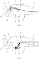
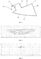
- a vehicle lamp module includes a lens 4, a shading plate 3 with a cut-off line structure 31 at one end, a low beam module and a high beam module, wherein light emitted by the low beam module is intercepted by the cut-off line structure 31 of the shading plate 3 and then emitted to the lens 4 to form a low beam type shown in Figure 10 .
- Light emitted by the high beam module is intercepted by the cut-off line structure 31 of the shading plate 3 and then emitted to the lens 4 to form a main high beam type located above a light and shade cut-off line and as shown in Figure 11 .
- the vehicle lamp module further includes an auxiliary high beam module, and light emitted by the auxiliary high beam module is intercepted by the cut-off line structure 31 of the shading plate 3 and then emitted to the lens 4 to form an auxiliary high beam type located below the light and shade cut-off line and as shown in Figure 12 .
- An existing vehicle lamp module can also switch high beam and low beam, but the formed high beam type has obvious defects, the brightness of the high beam above a light and shade cut-off line is higher than the brightness of the high beam below the light and shade cut-off line, a part below the light and shade cut-off line forms a dark area where the high beam is distributed, and the high beam type generates a brightness gradient in the shape of the light and shade cut-off line, so that not only is the road surface lighting effect of high beam affected, but also certain potential safety hazards exist; the vehicle lamp module improves the prior art to a certain degree, part of high beam or low beam light is refracted or reflected to be guided to the position below a light and shade cut-off line so as to supplement light to the dark area of the high beam, however, it is difficult to adjust light by using the method, and the manufacturing difficulty of part of optical elements in the vehicle lamp module is increased.
- the vehicle lamp module provided by the present disclosure is provided with the low beam module, the high beam module and the auxiliary high beam module, when the low beam module is activated, low beam light emitted by the low beam module is emitted to the shading plate 3, part of the low beam light is shielded by the shading plate 3, and part of the low beam light is emitted from the cut-off line structure 31 of the shading plate 3 and then refracted by the lens 4 to form a low beam type located below the light and shade cut-off line; when the high beam module is activated, high beam light emitted by the high beam module is reflected by the shading plate 3 and then refracted by the lens 4 to form a main high beam type located above the light and shade cut-off line, and the brightness of the main high beam is higher than that of the low beam; when the auxiliary high beam module is activated, light emitted by the auxiliary high beam module is emitted to the shading plate 3, part of the light is shielded by the shading plate 3, another part of the light is emitted from the cut-
- the low beam type, the main high beam type and the auxiliary high beam type are all light distribution patterns with light and shade cut-off lines, the light distribution pattern of the auxiliary high beam is matched with the shape of a dark area in the light distribution pattern of the conventional high beam, and the auxiliary high beam type, the low beam type and the main high beam type can be combined into high beam with uniform brightness.
- the low beam module includes a low beam condensing element 11 and a light source
- the high beam module includes a high beam condensing element 21 and a light source
- the auxiliary high beam module includes an auxiliary high beam condensing element 23 and a light source
- an LED light-emitting chip, an OLED light-emitting chip or a light-emitting chip based on a laser light source may be adopted as the light source;
- ellipsoidal or paraboloid reflection cups may be adopted as the low beam condensing element 11, the high beam condensing element 21 and the auxiliary high beam condensing element 23, or a condenser may also be adopted to play a role in condensing light.
- most of light emitted by the light source is converged to the cut-off line structure 31 of the shading plate 3 or near the cut-off line structure 31 by the low beam light condensing element 11, the high beam light condensing element 21 and the auxiliary high beam light condensing element 23, and the cut-off line structure 31 of the shading plate 3 is located on a focus of the lens 4 or near the focus. Due to such positioning, the light utilization rate can be improved, and a clearer light distribution pattern can be formed.
- the low beam condensing element 11, the high beam condensing element 21 and the auxiliary high beam condensing element 23 are all set as reflection cups which are correspondingly referred to as a low beam reflection cup, a high beam reflection cup and an auxiliary reflection cup respectively, and the reflection cups may be ellipsoidal reflection cups or paraboloid reflection cups.
- Perifocuses of the low beam reflection cup, the high beam reflection cup and the auxiliary reflection cup are respectively provided with a low beam light source 12, a high beam light source 22 and an auxiliary high beam light source 24, apofocuses of the reflection cups fall on the cut-offline structure 31 of the shading plate 3, and it should be understood that the reflection cup has two focuses, the perifocus is a light incident point, and the apofocus is a light emergent point. Due to such arrangement of the relative positions of the low beam reflection cup, the high beam reflection cup, the auxiliary reflection cup, the shading plate 3 and the lens 4, the light utilization rate can be increased, and the formed light type is clearer.
- the low beam reflection cup and the auxiliary reflection cup are assembled and connected or integrally formed to form a hyperboloid reflection cup, and the reflecting surface of the high beam reflection cup is opposite to the reflecting surface of the hyperboloid reflection cup.
- the reflecting surface of the high beam reflection cup being opposite to the reflecting surface of the hyperboloid reflection cup is not limited to the placement manner that the two reflecting surfaces are completely opposite, and as long as the light reflected by the hyperboloid reflection cup can be emitted to the upper surface of the shading plate 3, and the light reflected by the high beam reflection cup can be emitted to the lower surface of the shading plate 3, the reflecting surface of the hyperboloid reflection cup and the reflecting surface of the high beam reflection cup can be considered to be in an opposite arrangement state.
- the low beam reflection cup and the auxiliary reflection cup are integrated into the hyperboloid reflection cup, so that the number of optical elements of the vehicle lamp module is reduced; the hyperboloid reflection cup can be integrally formed, so that the production efficiency is improved, the production cost is reduced, and the light adjusting difficulty is reduced.
- the reflecting surface of the low beam reflection cup is arranged opposite to the reflecting surface of the high beam reflection cup and the reflecting surface of the auxiliary reflection cup.
- the radial size of the vehicle lamp module can be reduced.
- the low beam condensing element 11 is a low beam reflection cup
- the high beam condensing element 21, the auxiliary high beam condensing element 23 and the shading plate 3 are integrated into a high beam integrated condenser 5, so that the size of the vehicle lamp module and the number of optical elements in the vehicle lamp module can be reduced
- the high beam integrated condenser 5 can be integrally formed, so that the production efficiency is improved, and the production cost is reduced
- the multiple optical elements are integrated into one optical element without adjusting the relative positions of the high beam condensing element 21, the auxiliary high beam condensing element 23 and the shading plate 3 in the vehicle lamp module, so that the assembling difficulty and the light adjusting difficulty of the vehicle lamp module are further reduced.
- the high beam integrated condenser 5 is a transparent solid light conductor, and the high beam integrated condenser 5 is sequentially provided with or integrally formed with a light incident part 52, a light passing part and a light emergent part.
- the light incident part 52 is provided with a groove and a light incident surface protruding backwards, and the total high beam light source 51 is placed in the groove, due to the adoption of such a structure, light emitted by the total high beam light source 51 can be well collected, and the utilization rate of the light source can be improved;
- an upper total reflection surface 53 is formed on the upper surface of the light passing part, a lower total reflection surface 54 protruding outwards is formed on the lower surface of the light passing part, and light can be converged to the area of a cut-off line structure 57 of the high beam integrated condenser 5 after being reflected by the upper total reflection surface 53 and the lower total reflection surface 54;
- the light emergent part is provided with a first light emergent part 55
- the relative position of the low beam reflection cup relative to the high beam integrated condenser 5 is adjusted, so that the apofocus of the low beam reflection cup is located on the cut-off line structure 57 of the high beam integrated condenser 5 or in the area nearby the cut-off line structure 57, and light converged by the low beam reflection cup is emitted to the cut-off line structure 57, intercepted by the cut-off line structure 57 and then refracted by the lens 4 to form a low beam type, and light emitted from the first light emergent part 55 and the second light emergent part 56 is intercepted by the cut-offline structure 57 and then refracted by the lens 4 to form an auxiliary high beam type and a main high beam type respectively.
- the cut-off line structure 57 of the high beam integrated condenser 5 is located at the focus of the lens 4 so as to form a clearer light type, and certainly, the cut-offline structure 57 may also be located near the focus of the lens 4.
- the vehicle lamp module includes three ellipsoidal reflection cups, namely a low beam reflection cup, a high beam reflection cup and an auxiliary high beam reflection cup; the perifocuses of the low beam reflection cup, the high beam reflection cup and the auxiliary high beam reflection cup are respectively provided with a low beam light source 12, a high beam light source 22 and an auxiliary high beam light source 24, the apofocuses of the low beam reflection cup, the high beam reflection cup and the auxiliary high beam reflection cup all fall into the area of the cut-off line structure 31 of the shading plate 3, and the focus of the lens 4 is located near the cut-off line structure 31 of the shading plate 3, wherein the low beam reflection cup and the auxiliary high beam cup may be integrally formed into a hyperboloid reflection cup.
- the low beam light source 12 when the low beam light source 12 is activated, low beam light emitted by the low beam light source 12 is emitted to the shading plate 3, a small part of the light is reflected by the upper reflecting surface of the shading plate 3, and most of the light is emitted from the cut-off line structure 31 of the shading plate 3 and then refracted by the lens 4 to form a low beam type located below a light and shade cut-off line;
- the high beam light source 22 is activated, high beam light emitted by the high beam light source 22 is reflected to the lens 4 by the lower reflecting surface of the shading plate 3 and then refracted by the lens 4 to form a main high beam type located above the light and shade cut-off line, and the brightness of the main high beam is higher than that of the low beam;
- the auxiliary high beam light source 24 when the auxiliary high beam light source 24 is activated, light emitted by the auxiliary high beam light source 24 is emitted to the shading plate 3, part of the light is reflected by the upper reflecting surface of
- the auxiliary high beam below the light and shade cut-off line is superposed with the low beam and combined with the main high beam above the light and shade cut-off line to form the high beam, referring to Figure 10 to Figure 14 , so that in the vehicle lamp module provided by the present disclosure, the auxiliary high beam is used for supplementing light to the dark area of the high beam below the light and shade cut-off line so as to provide the high beam with higher and more uniform brightness; and the brightness of the high beam formed by superposition can be more uniform by adjusting the brightness of the low beam light source 12, the high beam light source 22 or the auxiliary high beam light source 24, and the light adjusting method is simple.
- the vehicle lamp module includes a low beam reflection cup and a high beam integrated condenser 5, the perifocus of the low beam reflection cup is provided with a low beam light source 12, and the apofocus of the low beam reflection cup falls on the cut-off line structure 57 of the high beam integrated condenser 5 or falls near the cut-off line structure 57; a total high beam light source 51 is arranged in a groove of a light incident part 52 of the high beam integrated condenser 5, and the cut-off line structure 57 coincides with the focus of the lens 4 or is located near the focus of the lens 4.
- the low beam light source 12 When low beam is started, the low beam light source 12 is activated, light converged by the low beam reflection cup is emitted to the cut-off line structure 57, part of the light is emitted to an upper total reflection surface 53 of a light passing part of the high beam integrated condenser 5 and then refracted downwards, and another part of the light is directly emitted to the lens 4 to form a low beam type; the total high beam light source 51 is activated, light emitted by the total high beam light source 51 is reflected by the upper total reflection surface 53 and a lower total reflection surface 54 of the light passing part, then emitted from the first light emergent part 55 and the second light emergent part 56 and converged near the cut-off line structure 57 of the high beam integrated condenser 5, and the light emitted from the first light emergent part 55 forms an auxiliary high beam type below the light and shade cut-off line, the light emitted from the second light emergent part 56 forms a main high beam type above
- the number of optical elements in the vehicle lamp module is further reduced, the size of the vehicle lamp module is reduced, and the high beam integrated condenser 5 is used for replacing the high beam condensing element 21, the auxiliary high beam condensing element 24 and the shading plate 3, so that the light adjusting difficulty of the vehicle lamp module is reduced, and the assembling speed of the vehicle lamp module is increased.
- a vehicle lamp provided by the present disclosure includes the optical module in the above technical solution, and adopts all the technical solutions of all the embodiments, and therefore the vehicle lamp at least has all the beneficial effects brought by the technical solutions of the embodiments.
Landscapes
- Engineering & Computer Science (AREA)
- General Engineering & Computer Science (AREA)
- Physics & Mathematics (AREA)
- Microelectronics & Electronic Packaging (AREA)
- Optics & Photonics (AREA)
- Non-Portable Lighting Devices Or Systems Thereof (AREA)
Applications Claiming Priority (2)
| Application Number | Priority Date | Filing Date | Title |
|---|---|---|---|
| CN201911228170.4A CN111076141A (zh) | 2019-12-04 | 2019-12-04 | 车灯模组及车灯 |
| PCT/CN2020/080903 WO2021109361A1 (fr) | 2019-12-04 | 2020-03-24 | Module de lampe de véhicule et lampe de véhicule |
Publications (4)
| Publication Number | Publication Date |
|---|---|
| EP4043784A1 true EP4043784A1 (fr) | 2022-08-17 |
| EP4043784A4 EP4043784A4 (fr) | 2023-08-30 |
| EP4043784B1 EP4043784B1 (fr) | 2026-03-11 |
| EP4043784C0 EP4043784C0 (fr) | 2026-03-11 |
Family
ID=70312728
Family Applications (1)
| Application Number | Title | Priority Date | Filing Date |
|---|---|---|---|
| EP20897594.6A Active EP4043784B1 (fr) | 2019-12-04 | 2020-03-24 | Module de lampe de véhicule et lampe de véhicule |
Country Status (5)
| Country | Link |
|---|---|
| US (1) | US20220390081A1 (fr) |
| EP (1) | EP4043784B1 (fr) |
| JP (1) | JP7404532B2 (fr) |
| CN (1) | CN111076141A (fr) |
| WO (1) | WO2021109361A1 (fr) |
Families Citing this family (11)
| Publication number | Priority date | Publication date | Assignee | Title |
|---|---|---|---|---|
| CN111486409A (zh) * | 2020-05-13 | 2020-08-04 | 海纳川海拉(天津)车灯有限公司 | 一种高光效光导结构及应用该结构的厚壁件 |
| CN113701120A (zh) * | 2020-05-22 | 2021-11-26 | 华域视觉科技(上海)有限公司 | 一种多像素远光系统、车灯及车辆 |
| CN113915583A (zh) * | 2020-07-09 | 2022-01-11 | 深圳市绎立锐光科技开发有限公司 | 照明装置及车辆用灯具 |
| CN112539393B (zh) * | 2020-11-16 | 2021-06-22 | 复旦大学 | 一种远光照明装置、车灯和车辆 |
| CN112902104A (zh) * | 2021-03-04 | 2021-06-04 | 广州市安亿仕电子科技有限公司 | 一种汽车前照灯装置 |
| CN118786310A (zh) | 2021-12-30 | 2024-10-15 | 华域视觉科技(上海)有限公司 | 灯具单元、前照灯和车辆 |
| CN115095832B (zh) * | 2022-06-22 | 2023-09-12 | 深圳市傲雷电商科技股份有限公司 | 一种远近光透镜模组及自行车车灯 |
| CN115949899A (zh) * | 2022-12-16 | 2023-04-11 | 苏州晶清光电科技有限公司 | 小体积双光透镜 |
| CN120457299A (zh) * | 2023-06-02 | 2025-08-08 | 华域视觉科技(上海)有限公司 | 一种车灯照明装置、车灯及汽车 |
| CN117227620A (zh) * | 2023-11-15 | 2023-12-15 | 华域视觉科技(上海)有限公司 | 车辆远近光控制系统、控制方法及车辆 |
| CN120194279A (zh) * | 2023-12-22 | 2025-06-24 | 法雷奥照明公司 | 照明模块、车辆前照灯和车辆 |
Family Cites Families (22)
| Publication number | Priority date | Publication date | Assignee | Title |
|---|---|---|---|---|
| CN2608829Y (zh) * | 2002-11-28 | 2004-03-31 | 上海正峰工业有限公司 | 一种远光灯辅助近照装置 |
| JP4413762B2 (ja) * | 2004-12-07 | 2010-02-10 | 株式会社小糸製作所 | 車両用照明灯具 |
| JP5114155B2 (ja) * | 2007-10-17 | 2013-01-09 | 株式会社小糸製作所 | 車両用前照灯ユニット |
| JP2009301980A (ja) | 2008-06-17 | 2009-12-24 | Koito Mfg Co Ltd | 灯具ユニット |
| JP5418760B2 (ja) | 2009-01-28 | 2014-02-19 | スタンレー電気株式会社 | 車両用灯具 |
| US8894257B2 (en) * | 2012-05-17 | 2014-11-25 | Osram Sylvania Inc. | Headlamp featuring both low-beam and high-beam outputs and devoid of moving parts |
| JP6236685B2 (ja) * | 2013-07-12 | 2017-11-29 | 市光工業株式会社 | 車両用前照灯 |
| JP2016039021A (ja) * | 2014-08-07 | 2016-03-22 | 株式会社小糸製作所 | 車両用灯具 |
| CN106574762B (zh) * | 2014-08-07 | 2022-06-03 | 株式会社小糸制作所 | 车辆用灯具 |
| JP6448250B2 (ja) * | 2014-08-11 | 2019-01-09 | 株式会社小糸製作所 | 車両用灯具 |
| DE102014226881A1 (de) * | 2014-12-22 | 2016-06-23 | Automotive Lighting Reutlingen Gmbh | Kraftfahrzeugscheinwerfer mit einem Zweikammerreflexionssystem |
| JP2017103189A (ja) | 2015-12-04 | 2017-06-08 | パナソニックIpマネジメント株式会社 | 前照灯及び移動体 |
| CN105570794B (zh) * | 2016-02-23 | 2018-02-06 | 上海小糸车灯有限公司 | 车灯led远近光一体带adb功能的pes单元 |
| JP2017212037A (ja) | 2016-05-23 | 2017-11-30 | スタンレー電気株式会社 | 車両用前照灯 |
| CN206001356U (zh) * | 2016-07-29 | 2017-03-08 | 浙江金驹汽车零部件有限公司 | 一种远近光合一的led照明模组 |
| JP6910138B2 (ja) * | 2016-12-14 | 2021-07-28 | 株式会社小糸製作所 | 車両用前照灯 |
| CN206555898U (zh) * | 2017-03-27 | 2017-10-13 | 刘浩 | 一种照射范围广、亮度集中的led车灯 |
| WO2018192963A1 (fr) * | 2017-04-19 | 2018-10-25 | Lumileds Holding B.V. | Système de phare de véhicule |
| KR102522911B1 (ko) * | 2017-10-31 | 2023-04-18 | 에스엘 주식회사 | 차량용 램프 |
| DE102018110793B4 (de) * | 2018-05-04 | 2026-02-05 | HELLA GmbH & Co. KGaA | Projektionsscheinwerfer |
| CN109681843A (zh) * | 2019-02-26 | 2019-04-26 | 华域视觉科技(上海)有限公司 | 车灯模组及应用其的汽车 |
| CN211450764U (zh) * | 2019-12-04 | 2020-09-08 | 华域视觉科技(上海)有限公司 | 车灯模组及车灯 |
-
2019
- 2019-12-04 CN CN201911228170.4A patent/CN111076141A/zh active Pending
-
2020
- 2020-03-24 JP JP2022528106A patent/JP7404532B2/ja active Active
- 2020-03-24 EP EP20897594.6A patent/EP4043784B1/fr active Active
- 2020-03-24 WO PCT/CN2020/080903 patent/WO2021109361A1/fr not_active Ceased
- 2020-03-24 US US17/776,838 patent/US20220390081A1/en not_active Abandoned
Also Published As
| Publication number | Publication date |
|---|---|
| EP4043784B1 (fr) | 2026-03-11 |
| CN111076141A (zh) | 2020-04-28 |
| WO2021109361A1 (fr) | 2021-06-10 |
| JP7404532B2 (ja) | 2023-12-25 |
| US20220390081A1 (en) | 2022-12-08 |
| EP4043784A4 (fr) | 2023-08-30 |
| EP4043784C0 (fr) | 2026-03-11 |
| JP2023501667A (ja) | 2023-01-18 |
Similar Documents
| Publication | Publication Date | Title |
|---|---|---|
| US20220390081A1 (en) | Vehicle lamp module and vehicle lamp | |
| CN110094686B (zh) | 机动车辆照明模块以及照明和/或信号指示装置 | |
| US7513642B2 (en) | LED collimator element with a semiparabolic reflector | |
| US7607811B2 (en) | Lighting unit | |
| US8690405B2 (en) | Vehicle lighting unit | |
| WO2013094222A1 (fr) | Système de phare comportant une fonction de faisceau adaptatif | |
| US20090080210A1 (en) | Motor Vehicle Headlight | |
| US20070177400A1 (en) | Vehicle lighting device | |
| JP2013546145A (ja) | Ledランプモジュール | |
| CN107859968B (zh) | 车灯照明系统、车灯总成及汽车 | |
| CN210568141U (zh) | 一种远近光一体的车灯模组、车灯和车辆 | |
| WO2022068267A1 (fr) | Module de feu de route adb et lampe de véhicule | |
| US12291142B2 (en) | Light path processing element, headlamp module vehicle lamp and vehicle | |
| CN211450764U (zh) | 车灯模组及车灯 | |
| CN213299956U (zh) | 车灯用光导体、远光照明模组及车灯 | |
| CN211316063U (zh) | 车灯模组、车辆前照灯及车辆 | |
| CN222047478U (zh) | 一种线路板、车灯模组和车灯 | |
| CN111735027B (zh) | 车灯模组、车辆前照灯及车辆 | |
| CN210219615U (zh) | 一种微型车灯模组 | |
| CN215446319U (zh) | 一种近光光学元件、车灯模组、车灯和车辆 | |
| CN209839955U (zh) | 车灯模组及车灯 | |
| CN212961373U (zh) | 远光照明系统和车灯 | |
| CN222186679U (zh) | 一种光学组件、汽车照明模组及汽车 | |
| CN223663188U (zh) | 遮光组件、近光光学模组、远近光一体模组和车灯 | |
| CN223709386U (zh) | 聚光器、远光模组、车灯及车辆 |
Legal Events
| Date | Code | Title | Description |
|---|---|---|---|
| STAA | Information on the status of an ep patent application or granted ep patent |
Free format text: STATUS: THE INTERNATIONAL PUBLICATION HAS BEEN MADE |
|
| PUAI | Public reference made under article 153(3) epc to a published international application that has entered the european phase |
Free format text: ORIGINAL CODE: 0009012 |
|
| STAA | Information on the status of an ep patent application or granted ep patent |
Free format text: STATUS: REQUEST FOR EXAMINATION WAS MADE |
|
| 17P | Request for examination filed |
Effective date: 20220512 |
|
| AK | Designated contracting states |
Kind code of ref document: A1 Designated state(s): AL AT BE BG CH CY CZ DE DK EE ES FI FR GB GR HR HU IE IS IT LI LT LU LV MC MK MT NL NO PL PT RO RS SE SI SK SM TR |
|
| DAV | Request for validation of the european patent (deleted) | ||
| DAX | Request for extension of the european patent (deleted) | ||
| A4 | Supplementary search report drawn up and despatched |
Effective date: 20230802 |
|
| RIC1 | Information provided on ipc code assigned before grant |
Ipc: F21W 107/10 20180101ALI20230727BHEP Ipc: F21W 102/13 20180101ALI20230727BHEP Ipc: F21S 41/663 20180101ALI20230727BHEP Ipc: F21S 41/40 20180101ALI20230727BHEP Ipc: F21S 41/36 20180101AFI20230727BHEP |
|
| STAA | Information on the status of an ep patent application or granted ep patent |
Free format text: STATUS: EXAMINATION IS IN PROGRESS |
|
| 17Q | First examination report despatched |
Effective date: 20240730 |
|
| GRAP | Despatch of communication of intention to grant a patent |
Free format text: ORIGINAL CODE: EPIDOSNIGR1 |
|
| STAA | Information on the status of an ep patent application or granted ep patent |
Free format text: STATUS: GRANT OF PATENT IS INTENDED |
|
| INTG | Intention to grant announced |
Effective date: 20251107 |
|
| GRAS | Grant fee paid |
Free format text: ORIGINAL CODE: EPIDOSNIGR3 |
|
| GRAA | (expected) grant |
Free format text: ORIGINAL CODE: 0009210 |
|
| STAA | Information on the status of an ep patent application or granted ep patent |
Free format text: STATUS: THE PATENT HAS BEEN GRANTED |
|
| AK | Designated contracting states |
Kind code of ref document: B1 Designated state(s): AL AT BE BG CH CY CZ DE DK EE ES FI FR GB GR HR HU IE IS IT LI LT LU LV MC MK MT NL NO PL PT RO RS SE SI SK SM TR |
|
| REG | Reference to a national code |
Ref country code: CH Ref legal event code: F10 Free format text: ST27 STATUS EVENT CODE: U-0-0-F10-F00 (AS PROVIDED BY THE NATIONAL OFFICE) Effective date: 20260311 Ref country code: GB Ref legal event code: FG4D |
|
| REG | Reference to a national code |
Ref country code: IE Ref legal event code: FG4D |
|
| U01 | Request for unitary effect filed |
Effective date: 20260317 |
|
| U07 | Unitary effect registered |
Designated state(s): AT BE BG DE DK EE FI FR IT LT LU LV MT NL PT RO SE SI Effective date: 20260320 |
|
| U20 | Renewal fee for the european patent with unitary effect paid |
Year of fee payment: 7 Effective date: 20260326 |