EP4043760A1 - Sealing arrangement, housing arrangement, transmission, industrial installation and computer program product - Google Patents
Sealing arrangement, housing arrangement, transmission, industrial installation and computer program product Download PDFInfo
- Publication number
- EP4043760A1 EP4043760A1 EP21156842.3A EP21156842A EP4043760A1 EP 4043760 A1 EP4043760 A1 EP 4043760A1 EP 21156842 A EP21156842 A EP 21156842A EP 4043760 A1 EP4043760 A1 EP 4043760A1
- Authority
- EP
- European Patent Office
- Prior art keywords
- seal
- sealing
- arrangement
- sealing arrangement
- designed
- Prior art date
- Legal status (The legal status is an assumption and is not a legal conclusion. Google has not performed a legal analysis and makes no representation as to the accuracy of the status listed.)
- Withdrawn
Links
Images

Classifications
-
- F—MECHANICAL ENGINEERING; LIGHTING; HEATING; WEAPONS; BLASTING
- F16—ENGINEERING ELEMENTS AND UNITS; GENERAL MEASURES FOR PRODUCING AND MAINTAINING EFFECTIVE FUNCTIONING OF MACHINES OR INSTALLATIONS; THERMAL INSULATION IN GENERAL
- F16J—PISTONS; CYLINDERS; SEALINGS
- F16J15/00—Sealings
- F16J15/16—Sealings between relatively-moving surfaces
- F16J15/164—Sealings between relatively-moving surfaces the sealing action depending on movements; pressure difference, temperature or presence of leaking fluid
-
- F—MECHANICAL ENGINEERING; LIGHTING; HEATING; WEAPONS; BLASTING
- F16—ENGINEERING ELEMENTS AND UNITS; GENERAL MEASURES FOR PRODUCING AND MAINTAINING EFFECTIVE FUNCTIONING OF MACHINES OR INSTALLATIONS; THERMAL INSULATION IN GENERAL
- F16C—SHAFTS; FLEXIBLE SHAFTS; ELEMENTS OR CRANKSHAFT MECHANISMS; ROTARY BODIES OTHER THAN GEARING ELEMENTS; BEARINGS
- F16C33/00—Parts of bearings; Special methods for making bearings or parts thereof
- F16C33/72—Sealings
- F16C33/76—Sealings of ball or roller bearings
- F16C33/80—Labyrinth sealings
-
- F—MECHANICAL ENGINEERING; LIGHTING; HEATING; WEAPONS; BLASTING
- F16—ENGINEERING ELEMENTS AND UNITS; GENERAL MEASURES FOR PRODUCING AND MAINTAINING EFFECTIVE FUNCTIONING OF MACHINES OR INSTALLATIONS; THERMAL INSULATION IN GENERAL
- F16J—PISTONS; CYLINDERS; SEALINGS
- F16J15/00—Sealings
- F16J15/002—Sealings comprising at least two sealings in succession
-
- F—MECHANICAL ENGINEERING; LIGHTING; HEATING; WEAPONS; BLASTING
- F16—ENGINEERING ELEMENTS AND UNITS; GENERAL MEASURES FOR PRODUCING AND MAINTAINING EFFECTIVE FUNCTIONING OF MACHINES OR INSTALLATIONS; THERMAL INSULATION IN GENERAL
- F16J—PISTONS; CYLINDERS; SEALINGS
- F16J15/00—Sealings
- F16J15/16—Sealings between relatively-moving surfaces
- F16J15/34—Sealings between relatively-moving surfaces with slip-ring pressed against a more or less radial face on one member
- F16J15/3436—Pressing means
- F16J15/3456—Pressing means without external means for pressing the ring against the face, e.g. slip-ring with a resilient lip
-
- F—MECHANICAL ENGINEERING; LIGHTING; HEATING; WEAPONS; BLASTING
- F16—ENGINEERING ELEMENTS AND UNITS; GENERAL MEASURES FOR PRODUCING AND MAINTAINING EFFECTIVE FUNCTIONING OF MACHINES OR INSTALLATIONS; THERMAL INSULATION IN GENERAL
- F16J—PISTONS; CYLINDERS; SEALINGS
- F16J15/00—Sealings
- F16J15/16—Sealings between relatively-moving surfaces
- F16J15/40—Sealings between relatively-moving surfaces by means of fluid
-
- F—MECHANICAL ENGINEERING; LIGHTING; HEATING; WEAPONS; BLASTING
- F16—ENGINEERING ELEMENTS AND UNITS; GENERAL MEASURES FOR PRODUCING AND MAINTAINING EFFECTIVE FUNCTIONING OF MACHINES OR INSTALLATIONS; THERMAL INSULATION IN GENERAL
- F16J—PISTONS; CYLINDERS; SEALINGS
- F16J15/00—Sealings
- F16J15/44—Free-space packings
- F16J15/447—Labyrinth packings
- F16J15/4472—Labyrinth packings with axial path
Definitions
- the invention relates to a sealing arrangement for sealing between a stationary and a rotating component.
- the invention also relates to a housing arrangement that has a corresponding sealing arrangement.
- the invention relates to a transmission with such a housing arrangement.
- the invention also relates to an industrial application with such a transmission and a computer program product for simulating an operating behavior of a corresponding sealing arrangement.
- a sealing arrangement which has a seal with a sealing lip.
- the component with the sealing lip is arranged in a rotating labyrinth seal component and is designed to release the sealing lip contact upon rotation.
- the seal with the sealing lip and the labyrinth seal are arranged at a radial distance from one another.
- the pamphlet WO 2006/005950 A2 several embodiments of a labyrinth seal are known, each of which creates a seal between a stationary and a rotating component.
- the labyrinth seals are provided with elastomeric sealing rings that make sealing contacts.
- the patent US 4,667,967 A1 discloses a sealing system used in the crankcase of an internal combustion engine.
- the sealing system includes a labyrinth seal and a seal with a sealing lip.
- the seal with the sealing lip is positioned on a side of the sealing system facing the environment.
- Gaskets and gasket assemblies are used in a variety of mechanical engineering applications. Increasing demands are being placed on these in terms of sealing effect, service life, ease of maintenance and cost efficiency. These requirements are made in particular in industrial applications that are designed for continuous operation, for example over weeks or months. The more sensitive the material to be processed in the industrial application, the stricter the requirements for the sealing effect.
- the object of the present invention is to provide a sealing arrangement which offers an improvement in at least one of the points outlined.
- the sealing arrangement serves to seal between a stationary component and a stationary component.
- a stationary component is understood to be a component that is stationary during normal operation, and a rotating component is a component that rotates relative to the stationary component during normal operation. This can be, for example, an area of a housing wall or a bearing cover and a shaft.
- the seal at least minimizes or completely prevents a lubricant, for example oil, from escaping into an environment. Likewise, the ingress of dirt from the environment is at least minimized or completely prevented by the sealing in the opposite direction.
- the sealing arrangement includes a first seal, which includes a centrifugal lifting sealing lip.
- the sealing arrangement includes a second seal which interacts with the first seal.
- the second seal designed as a non-contact labyrinth seal. In the non-contact labyrinth seal, the sealing effect is brought about by opposite and/or intermeshing, i.e. meshing, labyrinth components.
- the labyrinth seal is designed to force lubricant into areas when the rotating component is rotating sufficiently quickly, which at least minimizes or completely prevents leakage from the sealing arrangement.
- no components come into contact with one another that is subject to wear, so that the non-contact labyrinth seal is essentially maintenance-free.
- the sealing arrangement according to the invention offers an increased sealing effect through the second seal at speeds of the rotating component at which the centrifugal force-lifting sealing lip lifts off due to centrifugal force.
- the sealing lip that lifts off by centrifugal force can be designed in such a way that this occurs at speeds of the rotating component that essentially correspond to continuous operation.
- a sealing arrangement which is operated predominantly or essentially exclusively in continuous operation is consequently essentially wear-free during this time. At low speeds of the rotating component, at which the centrifugal lifting sealing lip is in contact, or at a standstill, this offers an increased sealing effect. Meanwhile, wear on the sealing lip caused by contact is minimized.
- the invention is based, among other things, on the surprising finding that an increased sealing effect is thereby achieved over the entire usable speed spectrum is, so an escape of lubricant into the environment and penetration of dirt from the environment can be reduced.
- the first seal with the centrifugal lift-off lip can be adjusted via a prestressing force to an operating point that essentially corresponds to a speed at which the sealing lip lifts off.
- the bearing assembly may be configured such that the first and second seals are non-contacting at at least a transition speed of the rotating component. The transition speed can be adjusted during assembly by selecting the preload force on the first seal.
- the first and second seals are arranged axially adjacent to one another.
- An axial direction is related to an axis of rotation of the rotating component.
- the axially adjacent arrangement includes both axially supporting the components of the first and second seals and a spaced arrangement such that the first seal is positioned axially in the region of the second seal, and vice versa. Due to the axially adjacent arrangement of the first and second seals, these can be selected as separate assemblies and can therefore be adapted to a large number of applications.
- the axially adjacent arrangement also extends an ingress path for dirt from the environment through the first seal.
- the first seal thus implements the principle of a non-contact labyrinth seal and serves to support the second seal in continuous operation.
- the sealing arrangement minimizes the radial dimensions of the sealing arrangement, in particular its outside diameter.
- the first and second gaskets can be assembled by an assembling force along the axial direction.
- the sealing arrangement can be assembled quickly by pushing it in, with precise positioning of the components being easily achievable. Overall, so the production cost for the installation of the sealing arrangement is reduced and maintenance is simplified.
- the first seal may be located on an environmental side of the seal assembly.
- the second seal can be arranged on the side of the seal arrangement facing the environment.
- the seal assembly is positioned between the environment and an interior space, where the interior space is richer in lubricant than the environment.
- the lubricant can be present there as a liquid and/or as an aerosol, for example oil mist.
- the first seal is mounted on the side facing away from the environment, ie the side facing the interior, and the second seal is mounted on the side of the sealing arrangement facing the environment, the first seal is at least partially wetted with lubricant.
- the outlined embodiment is based, among other things, on the surprising finding that an increase in the sealing effect of the sealing arrangement is also achieved in this way.
- the claimed sealing arrangement is also suitable for applications in which increased demands are placed on the cleanliness of the environment, for example for chip production or food processing.
- the attachment of the second seal on the side of the sealing arrangement facing the environment serves to increase a sealing effect, so that the sealing arrangement is suitably designed for use in an industrial application in chip production or food processing.
- the embodiment in which the first seal is arranged on the side of the seal arrangement facing the environment offers, on the other hand, easier accessibility of the sealing lip. As a result, wear and tear can easily be detected there and a sealing lip element to which the sealing lip is attached can be replaced quickly.
- the sealing lip that lifts off by centrifugal force can be arranged in the region of a rotatable wall of the second seal.
- the sealing lip element can be arranged directly adjacent to the rotatable wall of the second seal in the axial direction.
- the second wall may represent a portion of a labyrinth seal component that is rotationally connected to the rotating component of the seal assembly.
- the claimed sealing arrangement can be designed without O-rings.
- an O-ring is also to be understood as any other technically comparable sealing element.
- the claimed sealing arrangement thus realizes the concept of a sealing arrangement that is non-contact in continuous operation, with the first seal being designed to ensure a contact-based sealing effect when at a standstill.
- O-rings can be dispensed with, as a result of which the economic efficiency of the sealing arrangement is further increased.
- the mechanical losses in the seal due to friction are reduced.
- the first seal is designed as a radial seal.
- radial seals can be designed, for example, as a radial shaft seal.
- Radial seals are readily available in a variety of sizes and allow cost effective manufacture of the claimed seal assembly.
- a radial seal can be easily replaced.
- further technical developments in radial seals in the claimed sealing arrangement can be readily taken up by selecting appropriate radial seals.
- the claimed sealing arrangement can be expanded and is also suitable for particularly long-lasting industrial applications.
- radial seals, in particular radial shaft sealing rings allow reliable preservation when the vehicle is at a standstill. This allows, for example, safe storage and safe transport of transmissions with such a bearing arrangement.
- the sealing lip can be attached to the sealing lip element.
- the sealing lip can be formed on the sealing lip element.
- the sealing arrangement can also comprise a substantially L-shaped counterpart which, when assembled, interacts with the sealing lip.
- the contact is designed as a circumferential line contact and is caused by a restoring force of the sealing lip directed essentially radially inwards.
- the contact between the sealing lip and the L-shaped counterpart can thereby form a contact surface which is aligned essentially parallel to the axial direction.
- the contact surface can be arranged in particular in the area of a turning point of an exit path for lubricant or an entry path for dirt.
- the exit path or the entry path is essentially S-shaped in the area of the contact surface.
- the contact surface can be designed in such a way that in the area of the contact surface a local passage direction for lubricant is formed opposite to an overall passage direction.
- a return channel for lubricant can be formed between the first and second seals and/or on a side of the first seal facing away from the environment.
- the sealing lip element can be arranged on a side of the first seal facing away from the environment.
- the essentially L-shaped counterpart can be arranged on a side of the first seal that faces the environment.
- the sealing lip element represents the most sensitive component of the sealing arrangement and is protected from damage during an assembly or maintenance process by such an arrangement.
- the sealing lip element can thereby be arranged to be supported axially against a bearing of the rotating component. This allows precise assembly of the first seal, which can thereby have a reduced axial dimension.
- the claimed sealing arrangement is therefore space-saving.
- the claimed sealing arrangement can be arranged radially inside a bearing cap or a housing wall, in particular a hub.
- the sealing arrangement has reduced dimensions in the axial direction, so that it can easily be placed in a housing wall. This makes it possible to dispense with a bearing cap or to structurally simplify the bearing cap.
- the bearing cap can be designed as a disc-shaped cover. If the sealing arrangement is accommodated in a bearing cap, this can have reduced dimensions in the radial direction and/or axial direction.
- the claimed sealing arrangement can be used in the form of a retrofit kit for existing applications, for example gearboxes or geared motors. Due to the compactness of the claimed sealing arrangement, existing bearing caps offer sufficient space to implement the solution outlined. The technical meaningful operation of gearboxes and geared motors can be extended overall by the claimed sealing arrangement.
- the second seal can be at least partially filled with a viscous sealant.
- Viscous sealants include greases, for example, which offer an additional sealing effect between a rotating and a stationary labyrinth component, especially against the ingress of dust.
- the frictional forces caused by the viscous sealants are essentially negligible in continuous operation of the sealing arrangement. This also further increases the sealing effect of the claimed sealing arrangement.
- the present task is also solved by a housing arrangement according to the invention.
- the housing arrangement includes a housing wall, which separates an interior space from an environment.
- the housing wall has a hub in which a rotatable bearing is arranged.
- a shaft is rotatably mounted therein, which is to be understood as a rotating component within the meaning of the sealing arrangement according to the invention.
- a sealing arrangement which serves to protect the rotatable bearing, is positioned on a side of the rotatable bearing which faces the environment and which can be designed, for example, as a roller bearing or plain bearing.
- the bearing is arranged in the interior so that the sealing arrangement at least minimizes the escape of lubricant into the environment and the ingress of dirt from the environment.
- the sealing arrangement is designed according to one of the embodiments presented above.
- the underlying object is also achieved by a transmission according to the invention.
- the transmission includes a housing assembly that accommodates a gear set.
- the housing arrangement is designed according to one of the embodiments outlined above.
- the gear has an increased service life, resulting in reduced maintenance over its service life.
- the gear is also capable of being operated at increased speeds.
- the gearbox can also be used in applications where there are increased demands on the cleanliness of the environment, such as chip production or food processing. This expands the possible range of applications for existing gearboxes.
- the transmission can also be a transmission or a transmission unit of a geared motor.
- the industrial application includes a drive unit that provides drive power for a driven unit.
- the drive unit is connected to the output unit via a gearbox.
- the drive unit can be designed, for example, as an electric motor, internal combustion engine or hydraulic motor.
- the output unit can be designed as a mechanical application that characterizes the use of the industrial application, for example as a mill, vertical mill, sugar mill, cement mill, rock crusher, conveyor belt, pump, roller press, apron conveyor, tube mill, rotary kiln, rotating mechanism, agitator, agitator crusher, Lifting device, extruder, robot, garbage compactor or scrap baler.
- the service life of the sealing arrangement is increased by the sealing arrangement according to the invention, thereby increasing the reliability and cost-effectiveness of the corresponding industrial applications.
- a computer program product by means of which the operating behavior of a sealing arrangement can be simulated.
- a flow of lubricant from an interior space in the direction of an environment and its penetration behavior can be simulated at a first and/or second seal of the sealing arrangement. This can be done taking into account a rotation of a rotating component relative to a stationary component. Deformation behavior of a centrifugal force can depend on the speed of the rotating component sealing lip are simulated.
- the computer program product can have a physics module that allows fluid-mechanical simulations and/or deformation simulations.
- the physics module can have data interfaces via which boundary conditions, such as a lubricant temperature, an ambient temperature, a degree of contamination of the environment, etc., can be set.
- the physics module can have corresponding executable simulation routines.
- the simulation results can also be made available to other simulation-oriented computer program products via at least one data interface.
- the computer program product also includes a data set that depicts at least the structure of the sealing arrangement. According to the invention, the sealing arrangement is designed according to one of the embodiments outlined above.
- a sealing arrangement can be adapted and optimized to the circumstances of an application by means of the computer program product according to the invention.
- operation of the sealing arrangement can be simulated in advance in order to predict a time when failure or intolerable damage to the sealing arrangement is to be expected.
- the computer program product according to the invention allows a plausibility check of the sensor data. If a sufficient discrepancy is determined between the sensor data and the simulation results of the computer program product according to the invention, a defective sensor in a transmission or an industrial application can also be identified.
- the computer program product can be used to identify a defective sensor in an industrial application.
- the computer program product can be embodied as a so-called digital twin, for example. Such digital twins are, among other things, in the disclosure document U.S. 2017/286572 A1 described in more detail. The disclosure of U.S. 2017/286572 A1 is incorporated by reference into the present application.
- FIG 1 1 is a schematic representation of an embodiment of the claimed seal assembly 30 that includes a stationary component 32 and a rotating component 34 and is employable in a transmission 50 .
- the stationary component 32 is designed as a bearing cover 40 which is attached to a housing wall 37 and the rotating component 34 as a shaft 36.
- the shaft 36 is non-rotatably connected to a component of a wheel set 56, not shown in detail.
- the housing wall 37 is part of a housing arrangement 55 which essentially includes all of the standing components of a transmission 50 .
- the rotating component 34 is rotatably received about an axis of rotation 35 in a rotatable bearing 38 which is fastened in a hub 47 on the housing wall 37 .
- the housing wall 37 separates an environment 42 from an interior space 44 and thus defines a side 46 facing the environment and a side 48 facing away from the environment of the sealing arrangement 30 .
- contamination for example dust.
- a lubricant 33 is also present in the interior 44, for example in the form of drops or oil mist.
- the ingress of dirt from the environment 42 into the interior 44 is at least minimized by the sealing arrangement 30 .
- Escape of lubricant 33 into the environment 42 is also at least minimized by the sealing arrangement 30 .
- the sealing arrangement 30 comprises a first seal 10 which is designed as a radial seal 11 which comprises a sealing lip element 12 and a substantially L-shaped counterpart 14 .
- a sealing lip 13 that lifts off centrifugal force is formed on the sealing lip element 12 .
- the sealing lip element 12 is connected in a rotationally fixed manner to the rotating component 34 so that centrifugal force is exerted on the sealing lip element 12 as a result of its rotation 15 .
- a contact 17 between the L-shaped counterpart 14 and the centrifugal lifting sealing lip 13 is released at a contact surface 18 .
- a standstill or a correspondingly low speed i.e.
- the contact 17 is on the contact surface 18 between the centrifugal lifting sealing lip 13 and the L-shaped counterpart 14, through which a sealing effect of the sealing arrangement 30 is developed. Wear of the centrifugal lifting sealing lip 13 due to friction on the L-shaped counterpart 14 is minimized in this way. The friction between the L-shaped counterpart 14 and the centrifugal lifting sealing lip 13 is When the contact 17 is released, there is no friction of the centrifugal lifting sealing lip 13 . Due to the fact that the first seal 10 is arranged on the side 48 of the sealing arrangement 30 facing away from the environment, the sealing lip 13 which lifts off the centrifugal force and/or the L-shaped counterpart 14 are at least partially wetted with lubricant 33 . As a result, lubrication is ensured even when the contact 17 is present in the first seal 10, as a result of which the wear on the first seal 10 is further minimized.
- a second seal 20 is arranged adjacent to the first seal 10 on a side of the seal arrangement 30 facing the environment 42 .
- the second seal 20 is designed as a non-contact labyrinth seal 21 .
- the second seal 20 includes a first labyrinth component 22 and a second labyrinth component 24 mounted in mesh with one another.
- the second labyrinth component 24 is non-rotatably attached to the rotating component 34 such that a wall 26 of the second labyrinth component 24 of the rotation 15 of the rotating component 34 follows.
- the wall 26 is therefore to be regarded as a rotatable wall 26 .
- the second labyrinth component 24 is arranged adjacent to the sealing lip element 12 and can be supported on the sealing lip element 12 by an assembly force 45 along the axial direction 43 .
- the sealing lip element 12 in turn is positioned adjacent to the bearing 38 and can be supported on its inner ring 31 via the assembly force 45 .
- only rotating components ie the inner ring 31 of the bearing 38, the sealing lip element 12 and the second labyrinth component 24 are supported on one another.
- the first labyrinth component 22 is supported along the axial direction 43 against the L-shaped counterpart 14 of the first seal 10 .
- These components can also be assembled using an assembly force 45 in the axial direction 43 and each represent stationary components that are arranged in the stationary component 32 .
- the second seal 20 can additionally be at least partially fillable or filled with a viscous sealant 25, for example a grease.
- first labyrinth component 22 is pushed in the axial direction 43 by a V-ring 39 which is arranged on the rotating component 34 .
- the seal assembly 30 is disposed radially inward of the standing component 32 .
- An outward radial direction is in FIG 1 symbolized by the arrow 41.
- the first and second seals 10, 20 are arranged axially adjacent to one another such that the seal assembly 30 has a reduced outside diameter.
- the sealing arrangement 30 can be used in a transmission 50, which is FIG 1 is not shown in detail.
- the structure according to FIG 1 is depicted in a computer program product 70 configured to simulate the performance of the seal assembly 30 .
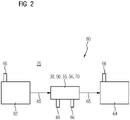
- FIG 2 shows schematically a structure of an embodiment of a claimed industrial application 60, which includes a drive unit 62, which is connected to a drive unit 64 via a gear 50.
- the drive unit 62 can be designed as an electric motor, an internal combustion engine or a hydraulic motor be and provide a drive power 65.
- the drive power 65 is supplied to the transmission 50 and passed on to the output unit 64 with a change in speed and torque.
- the output unit 64 is a mechanical application that characterizes the use of the industrial application 60 and is operated via the drive power 65 .
- the output unit 64 can be designed in such a way that the industrial application 60 can, for example, be a mill, vertical mill, sugar mill, cement mill, rock crusher, conveyor belt, pump, roller press, plate conveyor, tube mill, rotary kiln, rotating mechanism, agitator, agitated crusher, lifting device, extruder, robot, garbage press or scrap press.
- the industrial application 60 can be embodied as an application in chip production or food processing.
- the transmission 50 includes a housing assembly 55 in which a wheel set 56 was added.
- the housing arrangement 55 includes at least one sealing arrangement 30, which can be designed according to one of the embodiments outlined above.
- the sealing arrangement 30 is depicted in a computer program product 70 so that the operating behavior of the sealing arrangement 30 can be simulated.
- the plausibility of data from sensors 66, which can be attached to the transmission 50, the drive unit 62 and/or the output unit 64, can be checked by means of the computer program product 70.
- the computer program product 70 can be in a communicative data connection with a simulation environment 75 that is not outlined in detail.
- the computer program product 70 can be embodied as a so-called digital twin, which is part of the simulation environment 75 , which in turn is a digital twin of the industrial application 60 .
Abstract
Die Erfindung betrifft eine Dichtungsanordnung (30), die zur Abdichtung zwischen einer stehenden Komponente (32) und einer drehenden Komponente (34) dient. Die Dichtungsanordnung (30) umfasst eine erste Dichtung (10) mit einer fliehkraftabhebenden Dichtlippe (13) und eine zweite Dichtung (20). Erfindungsgemäß ist die zweite Dichtung (20) als berührungsfreie Labyrinthdichtung (21) ausgebildet. Die Erfindung betrifft auch eine Gehäuseanordnung (55), die eine erfindungsgemäße Dichtungsanordnung (30) aufweist. Ferner betrifft die Erfindung ein Getriebe (50), die mit einer solchen Gehäuseanordnung (55) ausgestattet ist, und eine entsprechend ausgerüstete Industrie-Applikation (60). Gleichermaßen betrifft die Erfindung ein Computerprogrammprodukt (70) zum Simulieren eine Betriebsverhaltens einer erfindungsgemäßen Dichtungsanordnung (30) .The invention relates to a sealing arrangement (30) which is used to seal between a stationary component (32) and a rotating component (34). The sealing arrangement (30) comprises a first seal (10) with a centrifugal lifting sealing lip (13) and a second seal (20). According to the invention, the second seal (20) is designed as a non-contact labyrinth seal (21). The invention also relates to a housing arrangement (55) which has a sealing arrangement (30) according to the invention. The invention also relates to a transmission (50) which is equipped with such a housing arrangement (55) and an industrial application (60) equipped accordingly. The invention also relates to a computer program product (70) for simulating an operating behavior of a sealing arrangement (30) according to the invention.
Description
Die Erfindung betrifft eine Dichtungsanordnung zur Abdichtung zwischen einer stehenden und einer drehenden Komponente. Die Erfindung betrifft ebenso eine Gehäuseanordnung, die über eine entsprechende Dichtungsanordnung verfügt. Ferner betrifft die Erfindung ein Getriebe mit einer solchen Gehäuseanordnung. Gleichermaßen betrifft die Erfindung eine Industrie-Applikation mit einem derartigen Getriebe und ein Computerprogrammprodukt zum Simulieren eines Betriebsverhaltens einer korrespondierenden Dichtungsanordnung.The invention relates to a sealing arrangement for sealing between a stationary and a rotating component. The invention also relates to a housing arrangement that has a corresponding sealing arrangement. Furthermore, the invention relates to a transmission with such a housing arrangement. The invention also relates to an industrial application with such a transmission and a computer program product for simulating an operating behavior of a corresponding sealing arrangement.
Aus dem Dokument
Die Druckschrift
Das Patent
Dichtungen und Dichtungsanordnungen werden in einer Vielzahl von Anwendungen im Maschinenbau eingesetzt. An diese werden steigende Anforderungen in puncto Dichtwirkung, Lebensdauer, Wartungsfreundlichkeit und Kosteneffizienz gestellt. Diese Anforderungen werden insbesondere in Industrie-Applikationen gestellt, die auf einen Dauerbetrieb, beispielsweise über Wochen oder Monate hinweg, ausgelegt sind. Je empfindlicher das Verarbeitungsgut der Industrie-Applikation ist, umso strenger sind insbesondere die Anforderungen an die Dichtwirkung. Der vorliegenden Erfindung liegt die Aufgabenstellung zugrunde, eine Dichtungsanordnung bereitzustellen, die in zumindest einer der skizzierten Punkte eine Verbesserung bietet.Gaskets and gasket assemblies are used in a variety of mechanical engineering applications. Increasing demands are being placed on these in terms of sealing effect, service life, ease of maintenance and cost efficiency. These requirements are made in particular in industrial applications that are designed for continuous operation, for example over weeks or months. The more sensitive the material to be processed in the industrial application, the stricter the requirements for the sealing effect. The object of the present invention is to provide a sealing arrangement which offers an improvement in at least one of the points outlined.
Die Aufgabenstellung wird durch eine erfindungsgemäße Dichtungsanordnung gelöst. Die Dichtungsanordnung dient zu einer Abdichtung zwischen einer stehenden Komponente und einer stehenden Komponente. Unter einer stehenden Komponente ist ein Bauteil zu verstehen, dass im bestimmungsgemäßen Betrieb stationär ist und unter einer drehenden Komponente ein Bauteil, das im bestimmungsgemäßen Betrieb relativ zur stehenden Komponente rotiert. Dies können beispielsweise ein Bereich einer Gehäusewandung oder ein Lagerdeckel und eine Welle sein. Durch die Abdichtung wird ein Austreten eines Schmierstoffs, beispielsweise Öl, in eine Umgebung zumindest minimiert oder komplett unterbunden. Ebenso wird durch die Abdichtung in die dazu entgegengesetzte Richtung ein Eindringen von Schmutz aus der Umgebung zumindest minimiert oder komplett unterbunden. Die Dichtungsanordnung umfasst eine erste Dichtung, die eine fliehkraftabhebende Dichtlippe umfasst. Durch eine hinreichend schnelle Rotation der drehenden Komponente wird eine Fliehkraft hervorgerufen, durch die ein Kontakt der Dichtlippe gelöst wird, und dadurch die Dichtwirkung der ersten Dichtung im Wesentlichen aufgehoben wird. Bei einer hinreichend langsamen Rotation oder im Stillstand der drehenden Komponente hingegen liegt die fliehkraftabhebende Dichtlippe an und entfaltet ihre Dichtwirkung. Des Weiteren umfasst die Dichtungsanordnung eine zweite Dichtung, die mit der ersten Dichtung zusammenwirkt. Erfindungsgemäß ist die zweite Dichtung als berührungsfreie Labyrinthdichtung ausgebildet. Bei der berührungsfreien Labyrinthdichtung wird die Dichtwirkung durch gegenüberliegend und/oder ineinandergreifende, also kämmende, Labyrinthkomponenten hervorgerufen. Die Labyrinthdichtung ist dazu ausgebildet, bei einer hinreichend schnellen Rotation der drehenden Komponente Schmierstoff in Bereiche zu zwingen, die ein Austreten aus der Dichtungsanordnung zumindest minimieren oder komplett unterbinden. Bei der berührungsfreien Labyrinthdichtung treten keine Bauteile miteinander in einen verschleißbehafteten Kontakt, so dass die berührungsfreie Labyrinthdichtung im Wesentlichen wartungsfrei ist. Zwischen den Labyrinthkomponenten kann sich bei der berührungsfreien Labyrinthdichtung entweder Luft oder ein Fluid befinden.The task is solved by a sealing arrangement according to the invention. The sealing arrangement serves to seal between a stationary component and a stationary component. A stationary component is understood to be a component that is stationary during normal operation, and a rotating component is a component that rotates relative to the stationary component during normal operation. This can be, for example, an area of a housing wall or a bearing cover and a shaft. The seal at least minimizes or completely prevents a lubricant, for example oil, from escaping into an environment. Likewise, the ingress of dirt from the environment is at least minimized or completely prevented by the sealing in the opposite direction. The sealing arrangement includes a first seal, which includes a centrifugal lifting sealing lip. Sufficiently rapid rotation of the rotating component causes a centrifugal force which loosens contact between the sealing lip and thereby essentially eliminates the sealing effect of the first seal. On the other hand, if the rotating component rotates sufficiently slowly or is at a standstill, the sealing lip that lifts off the centrifugal force makes contact and unfolds its sealing effect. Furthermore, the sealing arrangement includes a second seal which interacts with the first seal. According to the invention, the second seal designed as a non-contact labyrinth seal. In the non-contact labyrinth seal, the sealing effect is brought about by opposite and/or intermeshing, i.e. meshing, labyrinth components. The labyrinth seal is designed to force lubricant into areas when the rotating component is rotating sufficiently quickly, which at least minimizes or completely prevents leakage from the sealing arrangement. In the non-contact labyrinth seal, no components come into contact with one another that is subject to wear, so that the non-contact labyrinth seal is essentially maintenance-free. In the non-contact labyrinth seal, there can be either air or a fluid between the labyrinth components.
Die erfindungsgemäße Dichtungsanordnung bietet bei Drehzahlen der drehenden Komponente, bei denen die fliehkraftabhebende Dichtlippe fliehkraftbedingt abhebt, eine erhöhte Dichtwirkung durch die zweite Dichtung. Die fliehkraftabhebende Dichtlippe ist derart ausbildbar, dass dies bei Drehzahlen der drehenden Komponente eintritt, die im Wesentlichen einem Dauerbetrieb entsprechen. Eine Dichtungsanordnung, die überwiegende oder im Wesentlich ausschließlich in einem Dauerbetrieb betrieben wird, ist währenddessen folglich im Wesentlichen verschleißfrei. Bei niedrigen Drehzahlen der drehenden Komponente, bei denen die fliehkraftabhebende Dichtlippe anliegt, oder im Stillstand, bietet diese eine erhöhte Dichtwirkung. Währenddessen ist der durch den Kontakt der Dichtlippe hervorgerufene Verschleiß an dieser minimiert. Verschleiß an der Dichtlippe wird dadurch im Wesentlichen auf einen transienten Betrieb begrenzt, in dem die fliehkraftabhebende Dichtlippe abhebt oder wieder zum Anliegen kommt. Hierdurch werden die technisch nutzbare Lebensdauer der Dichtungsanordnung und die Wirtschaftlichkeit einer Industrie-Applikation, die mit einer solchen ausgestattet ist, gesteigert. Der Erfindung liegt unter anderem die überraschende Erkenntnis zugrunde, dass dadurch über das gesamte nutzbare Drehzahlspektrum hinweg eine gesteigerte Dichtwirkung erzielt wird, also ein Austritt von Schmierstoff in die Umgebung und ein Eindringen von Schmutz aus der Umgebung reduziert werden. Die erste Dichtung mit der fliehkraftabhebenden Lippe ist über eine Vorspannkraft ein Betriebspunkt einstellbar, der im Wesentlichen einer Drehzahl entspricht, bei dem die Dichtlippe abhebt. Die Wirksamkeit der beanspruchten Lageranordnung ist dadurch in einfacher Weise einstellbar. Die Lageranordnung kann dazu ausgebildet sein, dass bei mindestens einer Übergangsdrehzahl der drehenden Komponente die erste und zweite Dichtung berührungsfrei sind. Die Übergangsdrehzahl ist bei einer Montage durch Wählen der Vorspannkraft auf die erste Dichtung einstellbar.The sealing arrangement according to the invention offers an increased sealing effect through the second seal at speeds of the rotating component at which the centrifugal force-lifting sealing lip lifts off due to centrifugal force. The sealing lip that lifts off by centrifugal force can be designed in such a way that this occurs at speeds of the rotating component that essentially correspond to continuous operation. A sealing arrangement which is operated predominantly or essentially exclusively in continuous operation is consequently essentially wear-free during this time. At low speeds of the rotating component, at which the centrifugal lifting sealing lip is in contact, or at a standstill, this offers an increased sealing effect. Meanwhile, wear on the sealing lip caused by contact is minimized. As a result, wear on the sealing lip is essentially limited to transient operation, in which the sealing lip that lifts off due to centrifugal force lifts off or comes into contact again. This increases the technically usable service life of the sealing arrangement and the economic efficiency of an industrial application that is equipped with one. The invention is based, among other things, on the surprising finding that an increased sealing effect is thereby achieved over the entire usable speed spectrum is, so an escape of lubricant into the environment and penetration of dirt from the environment can be reduced. The first seal with the centrifugal lift-off lip can be adjusted via a prestressing force to an operating point that essentially corresponds to a speed at which the sealing lip lifts off. As a result, the effectiveness of the claimed bearing arrangement can be adjusted in a simple manner. The bearing assembly may be configured such that the first and second seals are non-contacting at at least a transition speed of the rotating component. The transition speed can be adjusted during assembly by selecting the preload force on the first seal.
In einer Ausführungsform der beanspruchten Dichtungsanordnung sind die erste und zweite Dichtung zueinander axial benachbart angeordnet. Eine Axialrichtung ist dabei auf eine Drehachse der drehenden Komponente bezogen. Die axial benachbarte Anordnung umfasst sowohl ein axiales Abstützen der von Komponenten der ersten und zweiten Dichtung als auch eine beabstandete Anordnung, so dass die erste Dichtung axial im Bereich der zweiten Dichtung positioniert ist, und umgekehrt. Durch die axial benachbarte Anordnung der ersten und zweiten Dichtung sind diese als separate Baugruppen auswählbar und dadurch an eine Vielzahl von Anwendungsfällen anpassbar. Durch die axial benachbarte Anordnung wird ferner eine Eintrittsstrecke für Schmutz aus der Umgebung durch die erste Dichtung verlängert. Die erste Dichtung verwirklicht so das Prinzip einer berührungslosen Labyrinthdichtung und dient einer Unterstützung der zweiten Dichtung im Dauerbetrieb. Die radialen Abmessungen der Dichtungsanordnung, insbesondere deren Außendurchmesser, werden hierdurch minimiert. Dies erlaubt es beispielsweise, an einem Lagerdeckel, an dem die Dichtungsanordnung anzubringen ist, mit reduziertem Innendurchmesser auszubilden. Ferner können die erste und zweite Dichtung durch eine Montagekraft entlang der Axialrichtung montiert werden. Die Dichtungsanordnung ist durch Einschieben schnell montierbar, wobei eine präzise Positionierung der Komponenten einfach erzielbar ist. Insgesamt wird so der Fertigungsaufwand für den Einbau der Dichtungsanordnung reduziert und eine Wartung vereinfacht.In one embodiment of the claimed sealing arrangement, the first and second seals are arranged axially adjacent to one another. An axial direction is related to an axis of rotation of the rotating component. The axially adjacent arrangement includes both axially supporting the components of the first and second seals and a spaced arrangement such that the first seal is positioned axially in the region of the second seal, and vice versa. Due to the axially adjacent arrangement of the first and second seals, these can be selected as separate assemblies and can therefore be adapted to a large number of applications. The axially adjacent arrangement also extends an ingress path for dirt from the environment through the first seal. The first seal thus implements the principle of a non-contact labyrinth seal and serves to support the second seal in continuous operation. This minimizes the radial dimensions of the sealing arrangement, in particular its outside diameter. This allows, for example, a bearing cap to which the sealing arrangement is to be fitted to be designed with a reduced inner diameter. Furthermore, the first and second gaskets can be assembled by an assembling force along the axial direction. The sealing arrangement can be assembled quickly by pushing it in, with precise positioning of the components being easily achievable. Overall, so the production cost for the installation of the sealing arrangement is reduced and maintenance is simplified.
In der beanspruchten Dichtungsanordnung kann die erste Dichtung auf einer umgebungszugewandten Seite der Dichtungsanordnung angeordnet sein. Alternativ kann die zweite Dichtung auf der umgebungszugewandten Seite der Dichtungsanordnung angeordnet sein. Die Dichtungsanordnung ist zwischen der Umgebung und einem Innenraum positioniert, wobei der Innenraum schmierstoffreicher ist als die Umgebung. Der Schmierstoff kann dort als Flüssigkeit und/oder als Aerosol, beispielsweise Ölnebel, vorliegen. In einer Ausführungsform, in der die erste Dichtung auf der umgebungsabgewandten Seite, also der innenraumzugewandten Seite, und die zweite Dichtung auf der umgebungszugewandten Seite der Dichtungsanordnung angebracht ist, wird die erste Dichtung zumindest teilweise mit Schmierstoff benetzt. Eine Benetzung mit Schmierstoff, beispielsweise durch Kontakt mit flüssigem Schmierstoff oder mit Ölnebel, gewährleistet einen verschleißarmen Betrieb der Dichtlippe. Dadurch wird auch in einem transienten Betrieb der Dichtungsanordnung der Verschleiß an der ersten Dichtung minimiert und die technisch nutzbare Lebensdauer der Dichtungsanordnung erhöht. Der skizzierten Ausführungsform liegt unter anderem die überraschende Erkenntnis zugrunde, dass so auch eine Steigerung der Dichtwirkung der Dichtungsanordnung erzielt wird. Infolge der gesteigerten Dichtwirkung ist die beanspruchte Dichtungsanordnung auch für Anwendungen geeignet, bei denen erhöhte Anforderungen an die Reinheit der Umgebung gestellt werden, beispielsweise für die Chip-Fertigung oder die Lebensmittelverarbeitung. Insgesamt dient das Anbringen der zweiten Dichtung auf der umgebungszugewandten Seite der Dichtungsanordnung dazu, eine Dichtwirkung zu steigern, so dass die Dichtungsanordnung zur Verwendung in einer Industrie-Applikation in der Chip-Fertigung oder der Lebensmittelverarbeitung geeignet ausgebildet ist.In the claimed seal assembly, the first seal may be located on an environmental side of the seal assembly. Alternatively, the second seal can be arranged on the side of the seal arrangement facing the environment. The seal assembly is positioned between the environment and an interior space, where the interior space is richer in lubricant than the environment. The lubricant can be present there as a liquid and/or as an aerosol, for example oil mist. In one embodiment, in which the first seal is mounted on the side facing away from the environment, ie the side facing the interior, and the second seal is mounted on the side of the sealing arrangement facing the environment, the first seal is at least partially wetted with lubricant. Wetting with lubricant, for example through contact with liquid lubricant or with oil mist, ensures low-wear operation of the sealing lip. As a result, the wear on the first seal is minimized even in transient operation of the sealing arrangement and the technically usable service life of the sealing arrangement is increased. The outlined embodiment is based, among other things, on the surprising finding that an increase in the sealing effect of the sealing arrangement is also achieved in this way. As a result of the increased sealing effect, the claimed sealing arrangement is also suitable for applications in which increased demands are placed on the cleanliness of the environment, for example for chip production or food processing. Overall, the attachment of the second seal on the side of the sealing arrangement facing the environment serves to increase a sealing effect, so that the sealing arrangement is suitably designed for use in an industrial application in chip production or food processing.
Die Ausführungsform, bei der die erste Dichtung auf der umgebungszugewandten Seite der Dichtungsanordnung angeordnet ist, bietet hingegen eine einfachere Zugänglichkeit der Dichtlippe. Infolgedessen ist dort ein Verschleiß ohne Weiteres feststellbar und ein Austausch eines Dichtlippenelements, an dem die Dichtlippe angebracht ist, schnell durchführbar.The embodiment in which the first seal is arranged on the side of the seal arrangement facing the environment offers, on the other hand, easier accessibility of the sealing lip. As a result, wear and tear can easily be detected there and a sealing lip element to which the sealing lip is attached can be replaced quickly.
Darüber hinaus kann die fliehkraftabhebende Dichtlippe im Bereich einer drehbaren Wandung der zweiten Dichtung angeordnet sein. Insbesondere kann das Dichtlippenelement in Axialrichtung unmittelbar benachbart zur drehbaren Wandung der zweiten Dichtung angeordnet sein. Die zweite Wandung kann einen Bereich einer Labyrinthdichtungskomponente darstellen, der drehfest mit der drehenden Komponente der Dichtungsanordnung verbunden ist. Hierdurch wird auch unter erheblichen Verformungen der Dichtungskomponente oder bei nicht sachgerechter Montage ein reibungsbehafteter Kontakt zwischen der ersten und zweiten Dichtung vermieden. Hierdurch wird insgesamt die Robustheit der beanspruchten Dichtungsanordnung gesteigert.In addition, the sealing lip that lifts off by centrifugal force can be arranged in the region of a rotatable wall of the second seal. In particular, the sealing lip element can be arranged directly adjacent to the rotatable wall of the second seal in the axial direction. The second wall may represent a portion of a labyrinth seal component that is rotationally connected to the rotating component of the seal assembly. In this way, contact between the first and second seals that is subject to friction is avoided even if the sealing component is subject to considerable deformation or if the assembly is not carried out properly. As a result, the overall robustness of the claimed sealing arrangement is increased.
Ferner kann die beanspruchte Dichtungsanordnung frei von O-Ringen ausgebildet sein. Im Sinne der vorliegenden Ausführungsform ist unter einem O-Ring auch jegliches andere technisch vergleichbare Dichtungselement zu verstehen. Die beanspruchte Dichtungsanordnung verwirklicht somit abgesehen von der ersten Dichtung das Konzept einer im Dauerbetrieb berührungsfreien Dichtungsanordnung, wobei die erste Dichtung dazu ausgebildet ist, bei Stillstand eine kontaktbehaftete Dichtwirkung gewährleistet. Infolge der überraschend gesteigerten Dichtungswirkung der beanspruchten Dichtungsanordnung sind O-Ringe entbehrlich, wodurch die Wirtschaftlichkeit der Dichtungsanordnung weiter gesteigert wird. Darüber hinaus werden durch den Verzicht auf O-Ringe die mechanischen Verluste in der Dichtung infolge von Reibung reduziert.Furthermore, the claimed sealing arrangement can be designed without O-rings. Within the meaning of the present embodiment, an O-ring is also to be understood as any other technically comparable sealing element. Apart from the first seal, the claimed sealing arrangement thus realizes the concept of a sealing arrangement that is non-contact in continuous operation, with the first seal being designed to ensure a contact-based sealing effect when at a standstill. As a result of the surprisingly increased sealing effect of the claimed sealing arrangement, O-rings can be dispensed with, as a result of which the economic efficiency of the sealing arrangement is further increased. In addition, since there are no O-rings, the mechanical losses in the seal due to friction are reduced.
In einer weiteren Ausführungsform der beanspruchten Dichtungsanordnung ist die erste Dichtung als Radialdichtung ausgebildet. Derartige Radialdichtungen können beispielsweise als Radialwellendichtring ausgebildet sein. Radialdichtungen sind in einer Vielzahl an Größen in einfacher Weise verfügbar und erlauben eine kosteneffiziente Herstellung der beanspruchten Dichtungsanordnung. Ferner ist eine Radialdichtung einfach austauschbar. Dadurch können technische Weiterentwicklungen bei Radialdichtungen in der beanspruchten Dichtungsanordnung ohne Weiteres durch Auswahl entsprechender Radialdichtungen aufgegriffen werden. Die beanspruchte Dichtungsanordnung ist dadurch ausbaubar und auch für besonders langlebige Industrie-Applikationen geeignet. Darüber hinaus erlauben Radialdichtungen, insbesondere Radialwellendichtringe eine zuverlässige Konservierung im Stillstand. Dies ermöglicht beispielsweise eine sichere Lagerung und einen sicheren Transport von Getrieben mit einer solchen Lageranordnung.In a further embodiment of the claimed sealing arrangement, the first seal is designed as a radial seal. Such radial seals can be designed, for example, as a radial shaft seal. Radial seals are readily available in a variety of sizes and allow cost effective manufacture of the claimed seal assembly. Furthermore, a radial seal can be easily replaced. As a result, further technical developments in radial seals in the claimed sealing arrangement can be readily taken up by selecting appropriate radial seals. As a result, the claimed sealing arrangement can be expanded and is also suitable for particularly long-lasting industrial applications. In addition, radial seals, in particular radial shaft sealing rings, allow reliable preservation when the vehicle is at a standstill. This allows, for example, safe storage and safe transport of transmissions with such a bearing arrangement.
Des Weiteren kann die Dichtlippe am Dichtlippenelement angebracht sein. Insbesondere kann die Dichtlippe am Dichtlippenelement angeformt sein. Die Dichtungsanordnung kann auch einen im Wesentlichen L-förmiges Gegenstück umfassen, das im montierten Zustand mit der Dichtlippe zusammenwirkt. Bei einer hinreichend niedrigen Drehzahl der drehenden Komponente liegt zwischen der Dichtlippe und dem im Wesentlichen L-förmigen Gegenstück der Kontakt vor, durch den die erste Dichtung eine Dichtwirkung entfaltet. Der Kontakt ist als umlaufender Linienkontakt ausgebildet und wird durch eine im Wesentlichen radial nach innen gerichtete Rückstellkraft der Dichtlippe hervorgerufen. Der Kontakt zwischen der Dichtlippe und dem L-förmigen Gegenstück kann dadurch eine Kontaktfläche ausbilden, die im Wesentlichen parallel zur Axialrichtung ausgerichtet ist. Die Kontaktfläche kann insbesondere im Bereich eines Wendepunkts eines Austrittspfades für Schmierstoff bzw. Eintrittspfades für Schmutz angeordnet sein. Der Austrittspfad bzw. der Eintrittspfad ist im Bereich der Kontaktfläche im Wesentlichen S-förmig ausgebildet. Insbesondere kann die Kontaktfläche derart ausgebildet sein, dass im Bereich der Kontaktfläche eine lokale Durchtrittsrichtung für Schmierstoff entgegengesetzt einer Gesamtdurchtrittsrichtung ausgebildet ist. Um in einem Stillstand einen Austritt von Schmierstoff zu erreichen, ist es erforderlich, dass Schmierstoff zumindest abschnittsweise in eine der Umgebung abgewandte Richtung fließt. Auch wenn der Kontakt der fliehkraftabhebenden Dichtlippe gelöst ist, wird so eine Dichtwirkung erzielt. Des Weiteren kann zwischen der ersten und zweiten Dichtung und/oder auf einer umgebungsabgewandten Seite der ersten Dichtung ein Rücklaufkanal für Schmierstoff ausgebildet sein.Furthermore, the sealing lip can be attached to the sealing lip element. In particular, the sealing lip can be formed on the sealing lip element. The sealing arrangement can also comprise a substantially L-shaped counterpart which, when assembled, interacts with the sealing lip. When the rotational speed of the rotating component is sufficiently low, there is contact between the sealing lip and the essentially L-shaped counterpart, as a result of which the first seal develops a sealing effect. The contact is designed as a circumferential line contact and is caused by a restoring force of the sealing lip directed essentially radially inwards. The contact between the sealing lip and the L-shaped counterpart can thereby form a contact surface which is aligned essentially parallel to the axial direction. The contact surface can be arranged in particular in the area of a turning point of an exit path for lubricant or an entry path for dirt. The exit path or the entry path is essentially S-shaped in the area of the contact surface. In particular, the contact surface can be designed in such a way that in the area of the contact surface a local passage direction for lubricant is formed opposite to an overall passage direction. In order to ensure that lubricant escapes when the machine is at a standstill, it is necessary for the lubricant to be directed away from the environment at least in sections direction flows. A sealing effect is achieved even if the contact of the centrifugally lifted sealing lip is released. Furthermore, a return channel for lubricant can be formed between the first and second seals and/or on a side of the first seal facing away from the environment.
Ferner kann das Dichtlippenelement auf einer der Umgebung abgewandten Seite der ersten Dichtung angeordnet sein. Korrespondierend kann das im Wesentlichen L-förmige Gegenstück auf einer der Umgebung zugewandten Seite der ersten Dichtung angeordnet sein. Das Dichtlippenelement stellt die empfindlichste Komponente der Dichtungsanordnung dar und wird durch eine solche Anordnung vor Beschädigungen bei einem Montage- oder Wartungsvorgang geschützt. Das Dichtlippenelement kann dadurch axial gegen ein Lager der drehenden Komponente abgestützt angeordnet werden. Dies erlaubt eine präzise Montage der ersten Dichtung, die dadurch eine reduzierte axiale Abmessung aufweisen kann. Die beanspruchte Dichtungsanordnung ist daher bauraumsparend.Furthermore, the sealing lip element can be arranged on a side of the first seal facing away from the environment. Correspondingly, the essentially L-shaped counterpart can be arranged on a side of the first seal that faces the environment. The sealing lip element represents the most sensitive component of the sealing arrangement and is protected from damage during an assembly or maintenance process by such an arrangement. The sealing lip element can thereby be arranged to be supported axially against a bearing of the rotating component. This allows precise assembly of the first seal, which can thereby have a reduced axial dimension. The claimed sealing arrangement is therefore space-saving.
Die beanspruchte Dichtungsanordnung kann radial innerhalb eines Lagerdeckels oder einer Gehäusewandung, insbesondere einer Nabe, angeordnet sein. Die Dichtungsanordnung weist in Axialrichtung reduzierte Abmessungen auf, so dass diese ohne Weiteren in einer Gehäusewandung platzierbar ist. Die erlaubt es, auf einen Lagerdeckel zu verzichten, oder den Lagerdeckel baulich zu vereinfachen. Beispielsweise kann der Lagerdeckel als scheibenförmige Abdeckung ausgebildet sein. Wenn die Dichtungsanordnung in einem Lagerdeckel aufgenommen ist, kann dieser im Radialrichtung und/oder Axialrichtung reduzierte Abmessungen aufweisen. Dadurch ist die beanspruchte Dichtungsanordnung in Form eines Nachrüstsatzes bei bestehenden Anwendungen, beispielsweise Getrieben oder Getriebemotoren, einsetzbar. Aufgrund der Kompaktheit der beanspruchten Dichtungsanordnung bieten bestehende Lagerdeckel hinreichend Bauraum um die skizzierte Lösung zu verwirklichen. Der technisch sinnvolle Betrieb von Getrieben und Getriebemotoren ist durch die beanspruchte Dichtungsanordnung insgesamt verlängerbar.The claimed sealing arrangement can be arranged radially inside a bearing cap or a housing wall, in particular a hub. The sealing arrangement has reduced dimensions in the axial direction, so that it can easily be placed in a housing wall. This makes it possible to dispense with a bearing cap or to structurally simplify the bearing cap. For example, the bearing cap can be designed as a disc-shaped cover. If the sealing arrangement is accommodated in a bearing cap, this can have reduced dimensions in the radial direction and/or axial direction. As a result, the claimed sealing arrangement can be used in the form of a retrofit kit for existing applications, for example gearboxes or geared motors. Due to the compactness of the claimed sealing arrangement, existing bearing caps offer sufficient space to implement the solution outlined. The technical meaningful operation of gearboxes and geared motors can be extended overall by the claimed sealing arrangement.
Darüber hinaus kann die zweite Dichtung zumindest teilweise mit einem viskosen Dichtstoff gefüllt sein. Zu den viskosen Dichtstoffen gehören beispielsweise Fette, die zwischen einer drehenden und einer stehenden Labyrinthkomponente eine zusätzliche Dichtwirkung, insbesondere gegen eindringenden Staub, bieten. Die durch die viskosen Dichtstoffe hervorgerufenen Reibungskräfte sind im Dauerbetrieb der Dichtungsanordnung im Wesentlichen vernachlässigbar. Auch dadurch wird die Dichtwirkung der beanspruchten Dichtungsanordnung weiter gesteigert.In addition, the second seal can be at least partially filled with a viscous sealant. Viscous sealants include greases, for example, which offer an additional sealing effect between a rotating and a stationary labyrinth component, especially against the ingress of dust. The frictional forces caused by the viscous sealants are essentially negligible in continuous operation of the sealing arrangement. This also further increases the sealing effect of the claimed sealing arrangement.
Die vorliegende Aufgabenstellung wird auch durch eine erfindungsgemäße Gehäuseanordnung gelöst. Die Gehäuseanordnung umfasst eine Gehäusewandung, durch die ein Innenraum von einer Umgebung getrennt wird. Die Gehäusewandung weist eine Nabe auf, in der ein drehbares Lager angeordnet ist. Darin ist eine Welle drehbar gelagert, die als drehende Komponente im Sinne der erfindungsgemäßen Dichtungsanordnung aufzufassen ist. Auf einer der Umgebung zugewandten Seite des drehbaren Lagers, das beispielsweise als Wälzlager oder Gleitlager ausgebildet sein kann, ist eine Dichtungsanordnung positioniert, die zu Schutz des drehbaren Lagers dient. Das Lager ist im Innenraum angeordnet, so dass durch die Dichtungsanordnung ein Austritt von Schmierstoff in die Umgebung und ein Eintritt von Schmutz aus der Umgebung zumindest minimiert wird. Erfindungsgemäß ist die Dichtungsanordnung nach einer der oben dargestellten Ausführungsformen ausgebildet.The present task is also solved by a housing arrangement according to the invention. The housing arrangement includes a housing wall, which separates an interior space from an environment. The housing wall has a hub in which a rotatable bearing is arranged. A shaft is rotatably mounted therein, which is to be understood as a rotating component within the meaning of the sealing arrangement according to the invention. A sealing arrangement, which serves to protect the rotatable bearing, is positioned on a side of the rotatable bearing which faces the environment and which can be designed, for example, as a roller bearing or plain bearing. The bearing is arranged in the interior so that the sealing arrangement at least minimizes the escape of lubricant into the environment and the ingress of dirt from the environment. According to the invention, the sealing arrangement is designed according to one of the embodiments presented above.
Ebenso wird die zugrundeliegende Aufgabe durch ein erfindungsgemäßes Getriebe gelöst. Das Getriebe umfasst eine Gehäuseanordnung, in der ein Radsatz aufgenommen ist. Erfindungsgemäß ist die Gehäuseanordnung nach einer der oben skizzierten Ausführungsformen ausgebildet. Das Getriebe ist weist eine gesteigerte Lebensdauer auf, woraus sich ein verringerter Wartungsaufwand über dessen Einsatzdauer ergibt. Das Getriebe ist auch dazu geeignet, bei erhöhten Geschwindigkeiten betrieben zu werden. Ebenso ist das Getriebe in Anwendungen einsetzbar, bei denen gesteigerte Anforderungen an die Reinheit der Umgebung gestellt werden, beispielsweise die Chip-Fertigung oder die Lebensmittelverarbeitung. Für bestehende Getriebe wird so das mögliche Einsatzspektrum erweitert. Das Getriebe kann dabei auch ein Getriebe bzw. eine Getriebeeinheit eines Getriebemotors sein.The underlying object is also achieved by a transmission according to the invention. The transmission includes a housing assembly that accommodates a gear set. According to the invention, the housing arrangement is designed according to one of the embodiments outlined above. The gear has an increased service life, resulting in reduced maintenance over its service life. The gear is also capable of being operated at increased speeds. The gearbox can also be used in applications where there are increased demands on the cleanliness of the environment, such as chip production or food processing. This expands the possible range of applications for existing gearboxes. The transmission can also be a transmission or a transmission unit of a geared motor.
Gleichermaßen wird die eingangs dargestellte Aufgabenstellung durch eine erfindungsgemäße Industrie-Applikation gelöst. Die Industrie-Applikation umfasst eine Antriebseinheit, durch die eine Antriebsleistung für eine Abtriebseinheit bereitgestellt wird. Die Antriebseinheit ist über ein Getriebe mit der Abtriebseinheit verbunden. Die Antriebseinheit kann beispielsweise als Elektromotor, Verbrennungsmotor oder Hydraulikmotor ausgebildet sein. Die Abtriebseinheit kann als mechanische Anwendung ausgebildet sein, durch die die Verwendung der Industrie-Applikation charakterisiert ist, beispielsweise als Mühle, Vertikalmühle, Zuckermühle, Zementmühle, Gesteinsbrecher, Förderband, Pumpe, Rollenpresse, Plattenband, Rohrmühle, Drehrohrofen, Drehwerk, Rührwerk, Rührzerkleinerer, Hubvorrichtung, Extruder, Roboter, Müllpresse oder Schrottpresse. Durch die erfindungsgemäße Dichtungsanordnung wird deren Lebensdauer gesteigert und dadurch die Zuverlässigkeit und Wirtschaftlichkeit der entsprechenden Industrie-Applikationen erhöht.Equally, the task presented at the outset is solved by an industrial application according to the invention. The industrial application includes a drive unit that provides drive power for a driven unit. The drive unit is connected to the output unit via a gearbox. The drive unit can be designed, for example, as an electric motor, internal combustion engine or hydraulic motor. The output unit can be designed as a mechanical application that characterizes the use of the industrial application, for example as a mill, vertical mill, sugar mill, cement mill, rock crusher, conveyor belt, pump, roller press, apron conveyor, tube mill, rotary kiln, rotating mechanism, agitator, agitator crusher, Lifting device, extruder, robot, garbage compactor or scrap baler. The service life of the sealing arrangement is increased by the sealing arrangement according to the invention, thereby increasing the reliability and cost-effectiveness of the corresponding industrial applications.
Ferner wird die oben dargelegte Aufgabe durch ein erfindungsgemäßes Computerprogrammprodukt gelöst, durch das das Betriebsverhaltens einer Dichtungsanordnung simulierbar ist. Dazu kann ein Fließen von Schmiermittel aus einem Innenraum in Richtung einer Umgebung und dessen Durchtrittsverhalten an einer ersten und/oder zweiten Dichtung der Dichtungsanordnung simuliert werden. Dies kann unter Berücksichtigung einer Rotation einer drehenden Komponente gegenüber einer stehenden Komponente erfolgen. Abhängig von einer Drehzahl der drehenden Komponente kann ein Verformungsverhalten einer fliehkraftabhebenden Dichtlippe simuliert werden. Dazu kann das Computerprogrammprodukt über ein Physikmodul verfügen, das fluidmechanische Simulationen und/oder Verformungssimulationen erlaubt. Das Physikmodul kann über Datenschnittstellen verfügen, über die Randbedingungen, wie beispielsweise eine Schmierstofftemperatur, eine Umgebungstemperatur, ein Kontaminationsgrad der Umgebung, usw. einstellbar sind. Das Physikmodul kann über entsprechende lauffähige Simulationsroutinen verfügen. Über zumindest eine Datenschnittstelle können die Simulationsresultate auch anderen simulationsgerichteten Computerprogrammprodukten zur Verfügung gestellt werden. Das Computerprogrammprodukt umfasst ferner einen Datensatz, durch den zumindest die Dichtungsanordnung in ihrem Aufbau abgebildet ist. Erfindungsgemäß ist die Dichtungsanordnung nach einer der oben skizzierten Ausführungsformen ausgebildet.Furthermore, the object set out above is achieved by a computer program product according to the invention, by means of which the operating behavior of a sealing arrangement can be simulated. For this purpose, a flow of lubricant from an interior space in the direction of an environment and its penetration behavior can be simulated at a first and/or second seal of the sealing arrangement. This can be done taking into account a rotation of a rotating component relative to a stationary component. Deformation behavior of a centrifugal force can depend on the speed of the rotating component sealing lip are simulated. For this purpose, the computer program product can have a physics module that allows fluid-mechanical simulations and/or deformation simulations. The physics module can have data interfaces via which boundary conditions, such as a lubricant temperature, an ambient temperature, a degree of contamination of the environment, etc., can be set. The physics module can have corresponding executable simulation routines. The simulation results can also be made available to other simulation-oriented computer program products via at least one data interface. The computer program product also includes a data set that depicts at least the structure of the sealing arrangement. According to the invention, the sealing arrangement is designed according to one of the embodiments outlined above.
Mittels des erfindungsgemäßen Computerprogrammprodukts ist eine Dichtungsanordnung an die Gegebenheiten einer Anwendung anpassbar und optimierbar. Zusätzlich ist ein Betrieb der Dichtungsanordnung im Voraus simulierbar um einen Zeitpunkt eines zu erwartenden Ausfalls oder intolerablen Beschädigung der Dichtungsanordnung zu prognostizieren. Im Zusammenwirken mit Sensordaten einer korrespondierenden realen Dichtungsanordnung erlaubt das erfindungsgemäße Computerprogrammprodukt eine Plausibilisierung der Sensordaten. Bei Feststellung einer hinreichenden Diskrepanz zwischen den Sensordaten und den Simulationsresultaten des erfindungsgemäßen Computerprogrammprodukts kann so auch ein defekter Sensor in einem Getriebe bzw. einer Industrie-Applikation identifiziert werden. Insgesamt kann das Computerprogrammprodukt zum Identifizieren eines defekten Sensors in einer Industrie-Applikation dienen. Dazu kann das Computerprogrammprodukt beispielsweise als sogenannter Digitaler Zwilling ausgebildet sein. Derartige Digitale Zwillinge sind unter anderem in der Offenlegungsschrift
Die Erfindung wird im Folgenden anhand einzelner Ausführungsformen in Figuren näher erläutert. Die Figuren sind insoweit in gegenseitiger Ergänzung zu lesen, dass gleiche Bezugszeichen in unterschiedlichen Figuren die gleiche technische Bedeutung haben. Die Merkmale der einzelnen Ausführungsformen sind untereinander auch kombinierbar. Ferner sind die in den Figuren gezeigten Ausführungsformen mit den oben skizzierten Merkmalen kombinierbar. Es zeigen im Einzelnen:
- FIG 1
- schematisch eine Ausführungsform der beanspruchten Dichtungsanordnung in einem Längsschnitt;
- FIG 2
- schematisch einen Aufbau einer Ausführungsform einer beanspruchten Industrie-Applikation.
- FIG 1
- schematically an embodiment of the claimed sealing arrangement in a longitudinal section;
- FIG 2
- schematically a structure of an embodiment of a claimed industrial application.
In
Die Dichtungsanordnung 30 umfasst eine erste Dichtung 10, die als Radialdichtung 11 ausgebildet ist, die ein Dichtlippenelement 12 und ein im Wesentlichen L-förmiges Gegenstück 14 umfasst. Am Dichtlippenelement 12 ist eine fliehkraftabhebende Dichtlippe 13 ausgebildet. Das Dichtlippenelement 12 ist drehfest mit der drehenden Komponente 34 verbunden, so dass durch deren Drehung 15 auf das Dichtlippenelement 12 Fliehkraft ausgeübt wird. Dadurch wird an einer Kontaktfläche 18 ein Kontakt 17 zwischen dem L-förmigen Gegenstück 14 und der fliehkraftabhebenden Dichtlippe 13 gelöst. Bei einem Stillstand oder einer entsprechend niedrigen Drehzahl, also einer langsamen Drehung 15, liegt der Kontakt 17 an der Kontaktfläche 18 zwischen der fliehkraftabhebenden Dichtlippe 13 und dem L-förmigen Gegenstück 14 vor, durch den eine Dichtwirkung der Dichtungsanordnung 30 entfaltet wird. Ein Verschleiß der fliehkraftabhebenden Dichtlippe 13 durch Reibung am L-förmigen Gegenstück 14 wird so minimiert. Die Reibung zwischen dem L-förmigen Gegenstück 14 und der fliehkraftabhebenden Dichtlippe 13 ist Wenn der Kontakt 17 gelöst ist, liegt keine Reibung der fliehkraftabhebenden Dichtlippe 13 vor. Dadurch, dass die erste Dichtung 10 auf der umgebungsabgewandten Seite 48 der Dichtungsanordnung 30 angeordnet ist, sind die fliehkraftabhebende Dichtlippe 13 und/oder das L-förmige Gegenstück 14 zumindest teilweise mit Schmierstoff 33 benetzt. Dadurch wird auch bei Vorliegen des Kontakts 17 in der ersten Dichtung 10 eine Schmierung gewährleistet, durch die der Verschleiß an der ersten Dichtung 10 weiter minimiert wird.The sealing
Auf einer der Umgebung 42 zugewandten Seite der Dichtungsanordnung 30 ist benachbart zur ersten Dichtung 10 eine zweite Dichtung 20 angeordnet. Die zweite Dichtung 20 ist als berührungsfreie Labyrinthdichtung 21 ausgebildet. Die zweite Dichtung 20 umfasst eine erste Labyrinthkomponente 22 und eine zweite Labyrinthkomponente 24, die miteinander kämmend montiert sind. Die zweite Labyrinthkomponente 24 ist drehfest an der drehenden Komponente 34 angebracht, so dass eine Wandung 26 der zweiten Labyrinthkomponente 24 der Drehung 15 der drehenden Komponente 34 folgt. Die Wandung 26 ist daher als drehbare Wandung 26 aufzufassen. Die zweite Labyrinthkomponente 24 ist benachbart zum Dichtlippenelement 12 angeordnet und ist durch eine Montagekraft 45 entlang der Axialrichtung 43 am Dichtlippenelement 12 abstützbar. Das Dichtlippenelement 12 wiederum ist benachbart zum Lager 38 positioniert und an dessen Innenring 31 über die Montagekraft 45 abstützbar. Infolgedessen sind ausschließlich drehende Bauteile, also der Innenring 31 des Lagers 38, das Dichtlippenelement 12 und die zweite Labyrinthkomponente 24 aneinander abgestützt. Die erste Labyrinthkomponente 22 ist entlang der Axialrichtung 43 gegen das L-förmige Gegenstück 14 der ersten Dichtung 10 abgestützt. Auch diese Bauteile sind über eine Montagekraft 45 in Axialrichtung 43 montierbar und stellen jeweils stehende Bauteile dar, die in der stehenden Komponente 32 angeordnet sind. Die zweite Dichtung 20 kann zusätzlich mit einem viskosen Dichtstoff 25, beispielsweise einem Fett, zumindest teilweise füllbar bzw. gefüllt sein. Ferner wird die erste Labyrinthkomponente 22 durch einen V-Ring 39, der auf der drehenden Komponente 34 angeordnet ist, in Axialrichtung 43 gedrückt. Die Dichtungsanordnung 30 ist radial innerhalb der stehenden Komponente 32 angeordnet. Eine nach außen weisende Radialrichtung ist in
Claims (14)
Priority Applications (1)
| Application Number | Priority Date | Filing Date | Title |
|---|---|---|---|
| EP21156842.3A EP4043760A1 (en) | 2021-02-12 | 2021-02-12 | Sealing arrangement, housing arrangement, transmission, industrial installation and computer program product |
Applications Claiming Priority (1)
| Application Number | Priority Date | Filing Date | Title |
|---|---|---|---|
| EP21156842.3A EP4043760A1 (en) | 2021-02-12 | 2021-02-12 | Sealing arrangement, housing arrangement, transmission, industrial installation and computer program product |
Publications (1)
| Publication Number | Publication Date |
|---|---|
| EP4043760A1 true EP4043760A1 (en) | 2022-08-17 |
Family
ID=74595159
Family Applications (1)
| Application Number | Title | Priority Date | Filing Date |
|---|---|---|---|
| EP21156842.3A Withdrawn EP4043760A1 (en) | 2021-02-12 | 2021-02-12 | Sealing arrangement, housing arrangement, transmission, industrial installation and computer program product |
Country Status (1)
| Country | Link |
|---|---|
| EP (1) | EP4043760A1 (en) |
Citations (9)
| Publication number | Priority date | Publication date | Assignee | Title |
|---|---|---|---|---|
| US4667967A (en) | 1985-10-04 | 1987-05-26 | Goetze Ag | Shaft sealing system with lip and labyrinth seals |
| JP2005257051A (en) * | 2004-03-15 | 2005-09-22 | Arai Pump Mfg Co Ltd | Sealing device |
| WO2006005950A2 (en) | 2004-07-12 | 2006-01-19 | Aes Engineering Limited | Seal |
| US20100201075A1 (en) | 2007-09-24 | 2010-08-12 | Alan James Roddis | Isolator sealing device |
| EP2990698A1 (en) * | 2014-08-26 | 2016-03-02 | Aktiebolaget SKF | Low-friction dynamic seal |
| US20170286572A1 (en) | 2016-03-31 | 2017-10-05 | General Electric Company | Digital twin of twinned physical system |
| CN107654354A (en) * | 2017-09-18 | 2018-02-02 | 沈阳理工大学 | A kind of cycloid axial direction labyrinth seal toothing |
| US20200080647A1 (en) * | 2018-09-10 | 2020-03-12 | BRUSS Sealing Systems GmbH | Shaft seal having a shaft sealing ring |
| CN112149327A (en) * | 2020-09-01 | 2020-12-29 | 中国石油大学(华东) | Bionic-based labyrinth seal fluid-solid-heat multi-field analysis and bearing heat insulation performance characterization method |
-
2021
- 2021-02-12 EP EP21156842.3A patent/EP4043760A1/en not_active Withdrawn
Patent Citations (9)
| Publication number | Priority date | Publication date | Assignee | Title |
|---|---|---|---|---|
| US4667967A (en) | 1985-10-04 | 1987-05-26 | Goetze Ag | Shaft sealing system with lip and labyrinth seals |
| JP2005257051A (en) * | 2004-03-15 | 2005-09-22 | Arai Pump Mfg Co Ltd | Sealing device |
| WO2006005950A2 (en) | 2004-07-12 | 2006-01-19 | Aes Engineering Limited | Seal |
| US20100201075A1 (en) | 2007-09-24 | 2010-08-12 | Alan James Roddis | Isolator sealing device |
| EP2990698A1 (en) * | 2014-08-26 | 2016-03-02 | Aktiebolaget SKF | Low-friction dynamic seal |
| US20170286572A1 (en) | 2016-03-31 | 2017-10-05 | General Electric Company | Digital twin of twinned physical system |
| CN107654354A (en) * | 2017-09-18 | 2018-02-02 | 沈阳理工大学 | A kind of cycloid axial direction labyrinth seal toothing |
| US20200080647A1 (en) * | 2018-09-10 | 2020-03-12 | BRUSS Sealing Systems GmbH | Shaft seal having a shaft sealing ring |
| CN112149327A (en) * | 2020-09-01 | 2020-12-29 | 中国石油大学(华东) | Bionic-based labyrinth seal fluid-solid-heat multi-field analysis and bearing heat insulation performance characterization method |
Similar Documents
| Publication | Publication Date | Title |
|---|---|---|
| DE2839233C2 (en) | ||
| DE102009006647B4 (en) | Dual clutch assembly | |
| DE102005025772A1 (en) | Torque transmitting unit for use in motor vehicle power train, has clutch input part supported in axial direction by clutch cover with intermediate bearing between clutch input part and clutch cover | |
| DE19539627A1 (en) | Power drive unit for aircraft cargo handling systems | |
| EP0217134A2 (en) | Sealing device for a shaft | |
| DE112013007520T5 (en) | Gear arrangement and method for controlling a gear arrangement | |
| DE102009034798A1 (en) | Rolling bearings, in particular single row deep groove ball bearings for a dual mass flywheel in a motor vehicle | |
| EP4043760A1 (en) | Sealing arrangement, housing arrangement, transmission, industrial installation and computer program product | |
| EP1122472B1 (en) | Sealing between a rotating shaft and a stationary housing | |
| DE102017106197B4 (en) | Rotating device | |
| EP3268634A1 (en) | Transmission having a planetary gear stage | |
| EP0683338A1 (en) | Shaft sealing system | |
| EP1125072B1 (en) | Sealing system for a drive unit consisting of a motor and a transmission | |
| DE202010002882U1 (en) | Pump drive of an automatic transmission comprising a hydrodynamic torque converter, in which the oil pump is not arranged coaxially with the torque converter | |
| DE19928450C2 (en) | labyrinth seal | |
| DE102009005775B4 (en) | Bearing seal arrangement | |
| EP1708951B1 (en) | Device for sealing escalator or moving pavement drives | |
| DE102018213593A1 (en) | Gearbox, in particular for a single wheel drive unit | |
| DE102022102436B3 (en) | Hybrid powertrain and hybrid module for this | |
| EP1457714B1 (en) | Transmission | |
| DE7616124U1 (en) | RADIAL OIL SEAL | |
| DE102008023289A1 (en) | Industrial drive for use in arrangement, has drive shaft which is provided on drive housing through opening, and gear wheel is connected with drive shaft, where brush or lamellar drive housing seal is arranged around drive shaft | |
| DE102009054198B4 (en) | Rotary bearing assembly with easier maintenance | |
| DE102006011620B3 (en) | Mechanical seal | |
| DE102019117014A1 (en) | Sealing arrangement and motorcycle gears and roller bearings therefor |
Legal Events
| Date | Code | Title | Description |
|---|---|---|---|
| PUAI | Public reference made under article 153(3) epc to a published international application that has entered the european phase |
Free format text: ORIGINAL CODE: 0009012 |
|
| STAA | Information on the status of an ep patent application or granted ep patent |
Free format text: STATUS: THE APPLICATION HAS BEEN PUBLISHED |
|
| AK | Designated contracting states |
Kind code of ref document: A1 Designated state(s): AL AT BE BG CH CY CZ DE DK EE ES FI FR GB GR HR HU IE IS IT LI LT LU LV MC MK MT NL NO PL PT RO RS SE SI SK SM TR |
|
| STAA | Information on the status of an ep patent application or granted ep patent |
Free format text: STATUS: THE APPLICATION IS DEEMED TO BE WITHDRAWN |
|
| 18D | Application deemed to be withdrawn |
Effective date: 20230218 |