EP4043641B1 - Selbstnivellierender eingebetteter strassenoberflächensensor - Google Patents
Selbstnivellierender eingebetteter strassenoberflächensensor Download PDFInfo
- Publication number
- EP4043641B1 EP4043641B1 EP21156246.7A EP21156246A EP4043641B1 EP 4043641 B1 EP4043641 B1 EP 4043641B1 EP 21156246 A EP21156246 A EP 21156246A EP 4043641 B1 EP4043641 B1 EP 4043641B1
- Authority
- EP
- European Patent Office
- Prior art keywords
- sensor
- road
- casing
- adjustment element
- level adjustment
- Prior art date
- Legal status (The legal status is an assumption and is not a legal conclusion. Google has not performed a legal analysis and makes no representation as to the accuracy of the status listed.)
- Active
Links
Images
Classifications
-
- E—FIXED CONSTRUCTIONS
- E01—CONSTRUCTION OF ROADS, RAILWAYS, OR BRIDGES
- E01C—CONSTRUCTION OF, OR SURFACES FOR, ROADS, SPORTS GROUNDS, OR THE LIKE; MACHINES OR AUXILIARY TOOLS FOR CONSTRUCTION OR REPAIR
- E01C23/00—Auxiliary devices or arrangements for constructing, repairing, reconditioning, or taking-up road or like surfaces
- E01C23/01—Devices or auxiliary means for setting-out or checking the configuration of new surfacing, e.g. templates, screed or reference line supports; Applications of apparatus for measuring, indicating, or recording the surface configuration of existing surfacing, e.g. profilographs
-
- E—FIXED CONSTRUCTIONS
- E01—CONSTRUCTION OF ROADS, RAILWAYS, OR BRIDGES
- E01F—ADDITIONAL WORK, SUCH AS EQUIPPING ROADS OR THE CONSTRUCTION OF PLATFORMS, HELICOPTER LANDING STAGES, SIGNS, SNOW FENCES, OR THE LIKE
- E01F11/00—Road engineering aspects of Embedding pads or other sensitive devices in paving or other road surfaces, e.g. traffic detectors, vehicle-operated pressure-sensitive actuators, devices for monitoring atmospheric or road conditions
-
- G—PHYSICS
- G01—MEASURING; TESTING
- G01B—MEASURING LENGTH, THICKNESS OR SIMILAR LINEAR DIMENSIONS; MEASURING ANGLES; MEASURING AREAS; MEASURING IRREGULARITIES OF SURFACES OR CONTOURS
- G01B11/00—Measuring arrangements characterised by the use of optical techniques
- G01B11/02—Measuring arrangements characterised by the use of optical techniques for measuring length, width or thickness
- G01B11/06—Measuring arrangements characterised by the use of optical techniques for measuring length, width or thickness for measuring thickness ; e.g. of sheet material
-
- G—PHYSICS
- G01—MEASURING; TESTING
- G01K—MEASURING TEMPERATURE; MEASURING QUANTITY OF HEAT; THERMALLY-SENSITIVE ELEMENTS NOT OTHERWISE PROVIDED FOR
- G01K13/00—Thermometers specially adapted for specific purposes
Definitions
- the present invention relates to a sensor apparatus that may be embedded in a road surface for monitoring conditions on the road surface.
- a durable surface material to withstand the wear and tear resulting over time due to traffic on the area and the mechanical abrasion resulting from maintenance operations applied on the surface material especially in winter conditions.
- Such surface material may be referred to as road surface or pavement and it may comprise e.g. asphalt and/or concrete.
- knowledge of conditions on the road surface is important for vehicles to make use of the area covered by the road surface in an efficient and safe manner.
- Particular examples in this regard include streets and roads experiencing high traffic as well as runways on airports.
- Such information may be readily applicable by drivers or pilots of vehicles rolling of the road surface while such information is valuable for estimating the need for road surface maintenance operations, especially in temperatures around zero degree Celsius.
- a known solution for monitoring conditions on the road surface involves usage of a road sensor that is embedded in the road surface to measure characteristics of interest on the road surface, such as temperature on the surface, a thickness of a water layer (possibly) residing on top of the surface, an amount of a predefined chemical (applied for road maintenance, such as de-icing) on the surface, etc.
- the road sensor may be able to report its measurement data to a central unit, which may process the measurement data into a human-readable format.
- such road sensors are applied in an arrangement of a plurality of road sensors embedded in the road surface across an area of interest, where each road sensor reports its measurement data to the central unit, which combines the measurement data from the plurality of road sensors and derives a report or other indication of the measured conditions on the road surface.
- a road sensor embedded therein may gradually become exposed, at some point to an extent that makes it protrude from the road surface. While this is likely to compromise measurement performance of the road sensor, it also makes the road sensor susceptible to damage due to being exposed to increased impact by wheels of vehicles rolling over it.
- maintenance equipment such as snow ploughs are typically applied to ensure safe traffic conditions: such road maintenance puts a road sensor protruding from the road surface at a significantly higher risk of damage due to impact from the maintenance equipment, while the maintenance may further increase the wear of the road surface.
- such operating conditions are ones where reliable information on conditions on the road surface may be most critical.
- a straightforward known solution to address the issues discussed above involves regular maintenance of the road sensors by a technician visiting on the site to check and, if needed, adjust positions of the road sensors such that they are embedded deep enough into the road surface to avoid unnecessary impacts by the traffic and maintenance operations.
- DE 102017210907 A1 discloses a road sensor apparatus for installation in a recess arranged in a pavement, a sensor casing, a sensor portion and an installation sleeve.
- the present invention is directed to a road sensor apparatus according to claim 1.
- an arrangement comprising a pavement covering an area intended for vehicular traffic, the pavement having a recess arranged therein and a road sensor apparatus according to the example embodiment described in the foregoing installed in said recess such that the first surface of the sensor casing is by a predefined margin below the level of a surface of the pavement and that the second surface of the sensor level adjustment element is arranged against a bottom of said recess.
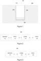
- FIG. 1 schematically illustrates some components of a road sensor apparatus 100 according to an example embedded in a recess arranged in a pavement 200 via a sealing layer 210.
- the road sensor apparatus 100 comprises a sensor casing 110 and a sensor level adjustment element 130 arranged within an installation sleeve 120.
- the installation sleeve 120 may comprise, at least conceptually, a side portion for interfacing the sides of the recess and a bottom portion for interfacing the bottom of the recess.
- the term pavement is applied to refer to a durable surfacing material laid on an area intended for vehicular traffic, such as on a road, a street, a runway, etc. Such surfacing material is also generally referred to as a road surface.
- the term pavement is applied herein, while in general the terms pavement and road surface may be used interchangeably.
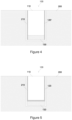
- Figure 2 illustrates a block diagram of some elements of the road sensor apparatus 100 arranged inside the sensor casing 110 according to an example.
- the road sensor apparatus 100 includes a sensor portion that comprises one or more sensor apparatuses for measuring respective environmental characteristics that pertain to conditions on the pavement 200, a processing portion 114 arranged to acquire respective measurement data from the one or more sensor apparatuses of the sensor portion 112 and a communication portion 116 arranged to provide communicative coupling to a processing unit 140 via a wired or wireless communication link and/or communication network.
- Figure 3 illustrates a block diagram of some elements of the road sensor apparatus 100 arranged inside the sensor casing 110 according to another example, where the processing portion 114 of Figure 2 is omitted and the functionality described therefor in the following may be provided in the processing unit 140 instead, mutatis mutandis.
- the sensor casing 110 defines a space therein, and the space within the sensor casing 110 houses at least some of the elements of the road sensor apparatus 100 illustrated vie examples of Figure 2 and 3 , i.e. the sensor portion 112 and the communication portion 116, possibly together with the processing portion 114.
- the sensor casing 110 has a first surface for interfacing environmental conditions on a surface of the pavement 200 and a second surface for interfacing the sensor level adjustment element 130, wherein the second surface may be a surface that is substantially opposite to the first surface.
- the sensor level adjustment element 130 has a first surface for interfacing the sensor casing 110 and a second surface for interfacing a bottom of the recess in the pavement 200 within which the road sensor apparatus 100 is to be embedded for operation, wherein the second surface may be a surface that is substantially opposite to the first surface.
- At least one of the one or more sensor apparatuses of the sensor portion 112 may be disposed within the sensor casing 110 close to its first surface, such that they are able to measure the respective environmental characteristics via the first surface of the sensor casing 120. Consequently, when the road sensor apparatus 100 is installed into the recess in the pavement 200, the sensor level adjustment element 130 is located below the sensor casing 110 and arranged against the bottom portion of the installation sleeve 120 and hence against (the sealing layer 210 in) the bottom of the recess, whereas the first surface of the sensor casing 110 is preferably arranged by a predefined margin below the level of the surface of the pavement 200, which margin may be for example in a range from 0 to 3 millimeters (mm), depending e.g. on the shape and size of the first surface of the sensor casing 110 and/or on characteristics of the sensor level adjustment element 130.
- the predefined margin may be also referred to as an installation depth of the road sensor apparatus 100.
- the respective first and second surfaces of the sensor casing 110 and the sensor level adjustment element 130 are typically, but not necessarily, respective substantially planar surfaces.
- the first surface of the sensor casing 110 may be also referred to as its top surface, first side or top side, whereas the second surface of the sensor casing 110 may be also referred to as its bottom surface, second side or bottom side.
- the first surface of the sensor level adjustment element 130 may be referred to as its top surface, first side or top side
- the second surface of the sensor level adjustment element 130 may be referred to as its bottom surface, second side or bottom side.
- the sensor level adjustment element 130 may comprise or it may be made of plastic material that exhibits permanent compression in response to being subjected to a pressure that exceeds a threshold pressure, which is characteristic to a construction of the sensor level adjustment element 130 and/or the plastic material applied therein.
- a threshold-exceeding pressure is applied on the top surface or on the bottom surface of the sensor level adjustment element 130
- plasticity of the sensor level adjustment element 130 results in compression of the sensor level adjustment element 130 such that the distance between its top and bottom surfaces becomes smaller.
- the sensor level adjustment element 130 retains its compressed form also when the threshold-exceeding pressure is no longer applied on its top or bottom surface.
- the sensor casing 110 is made of durable and substantially non-deformable and/or incompressible (e.g. rigid or stiff) material that is able to withstand at least pressures that are smaller than or equal to the threshold pressure of the sensor level adjustment element 130 substantially without deformation. Consequently, such a pressure applied on the top surface of the sensor casing 110 results in the bottom surface of the sensor casing 110 exerting a corresponding pressure on the sensor level adjustment element 130.
- the sensor casing 110 may be made of two-component polyurethane elastomer.
- the size and shape of the sensor casing 110 are selected according to circumstances, e.g. in view of the size and/or other requirements of the components arranged therein.
- the top surface of the sensor casing 110 may comprise a planar or substantially planar surface and it may have an area that is significantly smaller than a typical footprint of a tire of a vehicle expected to roll over the road sensor apparatus 100 when arranged in its location of usage.
- the top surface of the sensor casing 110 may have a substantially rectangular area whose diagonal is at most 100 mm or a substantially circular area whose diameter is in the at most 100 mm. In an example, the diagonal of a rectangular top surface or the diameter of a circular top surface may be approximately 55 mm.
- the sensor casing 110 may have an overall shape that approximates a rectangular cuboid or a cylinder having a height (from its top surface to its bottom surface) in a range from 100 to 600 mm, e.g. approximately 320 mm.
- the top surface of the sensor casing 110 may not be substantially planar and/or the sensor casing 110 may have a shape different from a substantially rectangular or circular one (e.g. hexagonal, elliptical, ...) having its longest diagonal or diameter at most 100 mm and the overall shape of the sensor casing 110 may be different from one that approximates a rectangular cuboid or a cylinder).
- the sensor level adjustment element 130 preferably has a shape that follows that of the sensor casing 110 in that its cross-section (in a direction perpendicular to its top and bottom surfaces) is not larger than that of the sensor casing 110, thereby enabling arrangement of the sensor level adjustment element 130 together with the sensor casing 110 within the installation sleeve 120.
- the cross-section of the sensor level adjustment element 130 may be substantially similar to that of the sensor casing 110, whereas in another example the cross-section of the sensor level adjustment element 130 may be smaller than that of the sensor casing 110.
- a thickness of the sensor level adjustment element 130 (e.g. the distance between its top and bottom surfaces) may be in a range from 15 to 50 mm, e.g. 30 mm, depending on the compression strength of the plastic material applied in the sensor level adjustment element 130 (and hence on the threshold pressure thereof) and/or on the desired amount of level adjustment enabled by the sensor level adjustment element 130.
- the threshold pressure of the sensor level adjustment element 130 may be the or substantially the same as a compression strength of the plastic material of the sensor level adjustment element 130.
- the threshold pressure needs to be sufficiently high to avoid compression of the sensor level adjustment element 130 to take place when the road sensor apparatus 110 is positioned in its intended installation depth at the predefined margin below the surface of the pavement 200 while on the other hand the threshold pressure needs to be sufficiently low to ensure compression when the top surface of the road sensor apparatus 100 is exposed at or above the surface of the pavement 200.
- the plastic material applied in the sensor level adjustment element 130 may comprise any plastic material having a compression strength in a range from 250 to 750 kPa, thereby resulting in the threshold frequency in the range from 250 to 750 kPa.
- the sensor level adjustment element 120 may comprise extruded polystyrene that may have a compression strength of approximately 300 kPa, thereby resulting in the threshold pressure of approximately 300 kPa.
- the sensor casing 110 and the sensor level adjustment element 130 may be arranged within the installation sleeve 120 such that at least the sensor casing 110 is able to move with respect to the installation sleeve 120 in response a pressure being applied on its top surface, the bottom surface of the sensor casing 110 thereby exerting a corresponding pressure on the sensor level adjustment element 130.
- the installation sleeve 120 may comprise a film that encloses an assembly formed by the sensor casing 110 and the sensor level adjustment element 130 apart from the top surface of the sensor casing 110.
- the installation sleeve 120 may comprise or be made of, for example, a polyvinyl chloride (PVC) film, which may have a thickness in a range from 100 to 200 micrometers ( ⁇ m), e.g. 150 ⁇ m.
- PVC polyvinyl chloride
- the road sensor apparatus 100 may be secured in its position in the recess arranged in the pavement 200 via the sealing layer 210 that serves to attach the outer surface of the installation sleeve 120 firmly in its position with respect to the recess.
- the sealing layer 210 may comprise or consist of a deformable sealing material that will subsequently solidify into the sealing layer 210 after the road sensor apparatus 100 has been arranged in its desired position with respect to the recess in the pavement 200.
- the sealing material may comprise, for example, two-component polyurethane elastomer. Consequently, the above-described movement of the sensor casing 110 with respect to the installation sleeve 120 results in the sensor casing 110 moving (downwards) with respect to the pavement 200 when a sufficient pressure is applied on its top surface.
- the sensor casing 110 and the sensor level adjustment element 130 may be arranged within the installation sleeve 120 such that the first surface of the sensor level adjustment element 130 is attached to the second surface of the sensor casing 110, either directly or via a fitting assembly.
- the sensor level adjustment element 130 is likewise moveable with respect to the installation sleeve 120 and a pressure applied on the top surface of the sensor casing 110 results in the sensor level adjustment element 130 moving along with the sensor casing 110.
- the sensor casing 110 and the sensor level adjustment element 130 may be arranged within the installation sleeve 120 such that the sensor level adjustment element 130 is, additionally or alternatively, attached to the installation sleeve 120 (e.g. to the side portion and/or to the bottom portion thereof) in a manner that does not allow movement with respect to the installation sleeve, thereby making the sensor level adjustment element 130 non-moveable with respect to the installation sleeve 120.
- a pressure applied on the top surface of the sensor casing 110 results in the bottom surface of the sensor casing 110 moving towards the sensor level adjustment element 130 and, consequently, exerting a corresponding pressure thereon.
- the installation sleeve 120 may be provided without the bottom portion, thereby providing an arrangement where the road sensor 100 may be arranged in the recess in the pavement 200 such that the bottom surface of the sensor level adjustment element 140 is directly facing (the sealing layer 210 at) the bottom of the recess without the installation sleeve 120 therebetween.
- the sensor level adjustment element 140 may be attached to the bottom surface of the sensor casing 110 and/or to the side portion of the installation sleeve 120.
- Figure 5 schematically illustrates a further example regarding the arrangement of the sensor casing 110 and the sensor level adjustment element 130 with respect to each other and with respect to the installation sleeve 120.
- the installation sleeve 120 encloses the sensor casing 110 apart from its top surface, whereas the sensor level adjustment element 130 is arranged adjacent to the bottom surface of the sensor casing 110 with the bottom portion of the installation sleeve 120 therebetween.
- the top surface of the sensor level adjustment element 130 may be attached to the bottom portion of the installation sleeve or the sensor level adjustment element 130 may be arranged at the bottom of the recess in the pavement 200 (against the sealing layer 210) before arranging the sensor casing 110 together with the installation sleeve 120 thereon.
- the installation sleeve 120, or at least the bottom portion thereof needs to be flexible or it needs to break upon the threshold-exceeding pressure being applied thereon to allow for the movement of the sensor casing 110 to transfer the threshold-exceeding pressure applied on the top surface thereof to the sensor level adjustment element 130.
- Figure 6 schematically illustrates a further example regarding the arrangement of the sensor casing 110 and the sensor level adjustment element 130 with respect to each other and with respect to the installation sleeve 120.
- the installation sleeve 120 is provided without the bottom portion and hence the bottom surface of the sensor casing 110 is directly facing the top surface of the sensor level adjustment element 130 without the installation sleeve 120 therebetween while the bottom surface of the sensor level adjustment element 130 is arranged against (the sealing layer 210 at) the bottom of the recess.
- the sensor casing 110 remains in its changed position with respect to the installation sleeve 120 also when the threshold-exceeding pressure is no longer applied on its top surface, thereby maintaining the desired level of the top surface of the sensor casing 110 with respect to the surface of the pavement 200.
- the road sensor apparatus 100 may be installed into a recess arranged in the pavement 200 via securing the outer surface of the installation sleeve 120 to an inner surface of the recess via the sealing layer 210.
- the depth of the recess is chosen such that it substantially matches the height of the road sensor apparatus 100, i.e. the distance from the top surface of the sensor casing 110 to the bottom surface of the sensor level adjustment element 120 or to the bottom portion of the installation sleeve 120 (whichever applies) in consideration of the predefined margin between the level of the top surface of the sensor casing 110 and the surface of the pavement 200 and the thickness of the sealing layer 210 at the bottom of the recess after installation.
- Installation of the road sensor apparatus 100 in the recess may involve inserting, into the recess, deformable sealing material that will subsequently solidify into the sealing layer 210 and arranging the road sensor apparatus 100 in the recess in a desired position with respect to the recess and the pavement 200 before the sealing material solidifies such that the top surface of the sensor casing 110 is arranged by the predefined margin below the surface of the pavement 200 while the bottom surface of the sensor level adjustment element 130 is arranged against (the sealing layer 210 at) the bottom of the recess (either directly or with the bottom portion of the installation sleeve 210 therebetween).
- the road sensor apparatus 100 serves to measure environmental characteristics that are descriptive of conditions on the surface of the pavement 200 at the location of the road sensor apparatus 100. Since the top surface of the sensor casing 110 is slightly below the surface of the pavement 200, no significant pressure is applied thereto by wheels of vehicles rolling over the road sensor apparatus 100 and the sensor casing 110 remains in its position with respect to pavement 200 (and with respect to the installation sleeve 120). On the other hand, due to gradual wear of the surface of the pavement 200 caused by wheels of vehicles rolling over the pavement 200 and by maintenance operations applied to the pavement 200 (e.g.
- the surface of the pavement 200 gradually comes closer to the top surface of the sensor casing 110 or even at level with top surface of the sensor casing 110, thereby exposing the top surface of the sensor casing 110 to an increased pressure from wheels of vehicles rolling over the road sensor apparatus 100.
- the pressure caused by wheels of vehicles rolling over the road sensor apparatus 100 increases to a level that exceeds the threshold pressure of the sensor level adjustment element 130, which results in compression of the sensor level adjustment element 130 and, consequently, in the sensor casing 110 moving closer to the bottom of the recess and its top surface moving (further) below the level of the surface of the pavement 200. Due to plastic characteristics of the sensor level adjustment element 130, the sensor casing 110 remains in its lowered position also when the threshold-exceeding pressure is no longer applied on the top surface thereof, thereby maintaining the position of its top surface suitably below the surface of the pavement 200.
- Such automated self-leveling ensures that the road sensor apparatus 100 continues to reliably measure the environmental conditions on the surface of the pavement 200 and it also avoids leaving the road sensor apparatus 100 exposed to impacts by road maintenance equipment (such as snow ploughs) applied for maintenance of the pavement 200, while on the other hand such self-leveling makes periodic manual maintenance work for keeping the top surface of the sensor casing 110 with a desired level with respect to the surface of the pavement 200 unnecessary.
- road maintenance equipment such as snow ploughs
- the level of the top surface of the sensor casing 110 with respect to the level of the surface of the pavement 200 that results in the threshold-exceeding pressure being applied thereon due to wheels of vehicles rolling over it depends, for example, on characteristics of the plastic material applied in the sensor level adjustment element 130 and the construction of the sensor level adjustment element 130, whereas also characteristic of the sensor casing 110, especially with respect to the shape and size of its top surface, may have an effect on the difference in respective levels of the top surface of the sensor casing 110 and the surface of the pavement 200 required for the threshold-exceeding pressure being applied on the top surface of the sensor casing 110.
- the size of the footprint of the wheel rolling over the sensor apparatus 100 likewise have an effect on the level difference between the top surface of the sensor casing 110 and the surface of the pavement 200 that results in self-leveling of the road sensor apparatus 100.
- characteristics of components of the road sensor apparatus 100 may be selected such that the threshold-exceeding pressure is triggered when the level difference between the top surface of the sensor casing 110 and the surface of the pavement 200 is smaller than the predefined margin described in the foregoing.
- the predefined margin discussed herein is necessarily an approximation.
- the sensor portion 112 may comprise a respective sensor apparatus for observing one or more environmental characteristics that are descriptive of conditions on the surface of the pavement 200.
- Non-limiting examples in this regard include the following:
- the processing portion 114 illustrated in the example of Figure 2 may comprise a microprocessor, a microcontroller or a corresponding programmable computing apparatus for acquiring respective measurement data from the one or more sensor apparatuses according to a predefined schedule, e.g. at predefined time intervals.
- the processing portion 114 may provide the measurement data acquired from the sensor portion 112 as such to the communication portion 116 for forwarding to the processing unit 140 via the communicative coupling.
- the processing portion 116 may apply predefined processing to derive processed measurement data on basis of the measurement data obtained from the sensor portion 112 and provide the processed measurement data to the communication portion 116 for forwarding to the processing unit 140.
- the processed measurement data may be derived on basis of respective measurement data obtained from one or more sensor apparatuses, e.g. respective measurement data obtained from a single sensor apparatus over time, on basis of instantaneous (e.g. the most recent) values of respective sensor data received from two or more sensors, or on basis of respective measurement data obtained from two or more sensor apparatuses over time.
- processing may include one or more of the following:
- the communication portion 116 may provide the communicative coupling to the processing unit 140 via a wired or wireless communication medium.
- the communicative coupling may enable provision of the measurement data from the road sensor apparatus 100 to the processing unit 140 and it may further enable providing control information from the processing unit 140 to the road sensor apparatus 100.
- the communicative coupling may be provided via one or more electrical cables.
- the communication portion 116 serves as an interface between the processing portion 116 and the one or more electrical cables, e.g. in order to convert the measurement data from the format applied by the processing portion 114 into a format (more) suitable for transmission via the one or more electrical cables.
- the communicative coupling may be provided using a suitable wireless communication technique known in the art, such as cellular wireless communication or short-range wireless communication (such as Bluetooth or Wi-FI).
- a suitable wireless communication technique such as cellular wireless communication or short-range wireless communication (such as Bluetooth or Wi-FI).
- the communication portion 116 may serve as a transmitter or a transceiver that is capable of communicating using the employed wireless communication technique.
- the processing unit 140 may be communicatively coupled to the road sensor apparatus 100 installed in a certain location in the pavement 200 and the processing unit 140 may receive the measurement data from the road sensor apparatus 100.
- the data received from the road sensor apparatus 100 may comprise the measurement data acquired from the sensor portion 112 as such or processed measurement data derived by the processing portion 114.
- the processing of measurement data described in the foregoing with references to the processing portion 114 may be carried out in the processing unit 140 instead, thereby obtaining the processed measurement data on basis of the measurement data acquired from the sensor portion 112.
- the processing unit 140 may process (e.g.
- the processing unit 140 may store the measurement data obtained from the road sensor apparatus 100 in a memory provided in the processing unit 140 for subsequent use therein.
- the processing unit 140 may receive respective measurement data from a plurality of road sensor apparatuses 100 installed in respective plurality of locations in the pavement 200 within a certain area and the processing unit 140 may receive respective measurement data from the plurality of road sensor apparatuses 100.
- the respective measurement data originating from the plurality of road sensor apparatuses 100 may be processed separately in a manner described above for a single road sensor apparatus 100 and displayed via the display device as respective indications of pavement surface conditions in the respective plurality of locations.
- the processing unit 140 may process the respective measurement data originating from the plurality of sensor apparatuses 100 may be combined into combined measurement data before displaying the combined measurement data via the display.
- the combination of measurement data may involve e.g. one of an average, a median, a mode, a minimum, a maximum or some other statistical measure derived based on respective measurement data originating from the plurality of road sensor apparatuses 100.
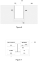
- FIG. 7 illustrates a block diagram of some components of an apparatus 300 that may be employed to implement the control portion 114 or the control unit 140 described in the foregoing.
- the apparatus 300 comprises a processor 310 and a memory 320.
- the memory 320 may store data and computer program code 325.
- the apparatus 300 may further comprise communication means 330 for wired or wireless communication with other apparatuses and/or user I/O (input/output) components 340 that may be arranged, together with the processor 310 and a portion of the computer program code 325, to provide the user interface for receiving input from a user and/or providing output to the user.
- the user I/O components may include user input means, such as one or more keys or buttons, a keyboard, a touchscreen or a touchpad, etc.
- the user I/O components may include output means, such as a display or a touchscreen.
- the components of the apparatus 300 are communicatively coupled to each other via a bus 350 that enables transfer of data and control information between the components.
- the memory 320 and a portion of the computer program code 325 stored therein may be further arranged, with the processor 310, to cause the apparatus 300 to perform at least some aspects of respective operation of the processing portion 114 or the processing unit 140 described in the foregoing.
- the processor 310 is configured to read from and write to the memory 320.
- the processor 310 is depicted as a respective single component, it may be implemented as respective one or more separate processing components.
- the memory 320 is depicted as a respective single component, it may be implemented as respective one or more separate components, some or all of which may be integrated/removable and/or may provide permanent / semi-permanent/ dynamic/cached storage.
- the computer program code 325 may comprise computer-executable instructions that implement at least some aspects of respective operation of the processing portion 114 or the processing unit 140 described in the foregoing when loaded into the processor 310.
- the computer program code 325 may include a computer program consisting of one or more sequences of one or more instructions.
- the processor 310 is able to load and execute the computer program by reading the one or more sequences of one or more instructions included therein from the memory 320.
- the one or more sequences of one or more instructions may be configured to, when executed by the processor 310, cause the apparatus 300 to perform at least some aspects of respective operation of the processing portion 114 or the processing unit 140 described in the foregoing.
- the apparatus 300 may comprise at least one processor 310 and at least one memory 320 including the computer program code 325 for one or more programs, the at least one memory 320 and the computer program code 325 configured to, with the at least one processor 310, cause the apparatus 300 to perform at least some aspects of respective operation of the processing portion 114 or the processing unit 140 described in the foregoing.
- the computer program code 325 may be provided e.g. a computer program product comprising at least one computer-readable non-transitory medium having the computer program code 325 stored thereon, which computer program code 325, when executed by the processor 310 causes the apparatus 300 to perform at least some aspects of respective operation of the processing portion 114 or the processing unit 140 described in the foregoing.
- the computer-readable non-transitory medium may comprise a memory device or a record medium such as a CD-ROM, a DVD, a Blu-ray disc or another article of manufacture that tangibly embodies the computer program.
- the computer program may be provided as a signal configured to reliably transfer the computer program.
- references(s) to a processor herein should not be understood to encompass only programmable processors, but also dedicated circuits such as field-programmable gate arrays (FPGA), application specific circuits (ASIC), signal processors, etc.
- FPGA field-programmable gate arrays
- ASIC application specific circuits
- signal processors etc.
Landscapes
- Engineering & Computer Science (AREA)
- Physics & Mathematics (AREA)
- General Physics & Mathematics (AREA)
- Architecture (AREA)
- Civil Engineering (AREA)
- Structural Engineering (AREA)
- General Engineering & Computer Science (AREA)
- Road Signs Or Road Markings (AREA)
- Road Repair (AREA)
Claims (13)
- Straßensensorvorrichtung (100) zur Installation in einer Vertiefung, die in einem Straßenbelag (200) zum Messen einer oder mehrerer Umwelteigenschaften auf einer Oberfläche des Straßenbelags (200) zu messen, wobei die Straßensensorvorrichtung (100) umfasst:ein Sensorhöheneinstellelement (130);ein Sensorgehäuse (110), das eine erste Oberfläche zum Erfassen von Umweltbedingungen auf der Oberfläche des Straßenbelags (200), eine zweite Oberfläche zum Ankoppeln an das Sensorhöheneinstellelement (130) und einen Sensorabschnitt (112) umfasst, der eine oder mehrere Sensorvorrichtungen zum Messen jeweiliger Umweltmerkmale auf der ersten Oberfläche des Sensorgehäuses (110) enthält, wobei das Sensorhöheneinstellelement (130) Kunststoffmaterial umfasst, das eine dauerhafte Kompression aufweist, wenn es einem Druck ausgesetzt ist, der einen Schwellendruck überschreitet, und eine erste Oberfläche zum Ankoppeln an das Sensorgehäuse (110) und eine zweite Oberfläche zum Ankoppeln an einen Boden der Vertiefung aufweist; undeine Installationshülse (120) zum Befestigen der Straßensensorvorrichtung (100) an der Vertiefung, wobei das Sensorgehäuse (110) und das Sensorhöheneinstellelement (130) aneinander angrenzend angeordnet sind und wobei mindestens das Sensorgehäuse (110) innerhalb der Installationshülse (120) so angeordnet ist, dass das Sensorgehäuse (110) in Bezug auf die Installationshülse (120) als Reaktion auf einen auf seine erste Oberfläche ausgeübten Druck, der den Schwellendruck überschreitet, bewegbar ist.
- Straßensensorvorrichtung (100) gemäß Anspruch 1, wobei die erste Oberfläche des Sensorhöheneinstellelements (130) an der zweiten Oberfläche des Sensorgehäuses (110) so angebracht ist, dass das Sensorhöheneinstellelement (130) in Bezug auf die Installationshülse (120) bewegbar ist.
- Straßensensorvorrichtung (100) gemäß Anspruch 1, wobei die erste Oberfläche des Sensorhöheneinstellelements (130) so an die zweite Oberfläche des Sensorgehäuses (110) angrenzend angeordnet ist, dass das Sensorgehäuse (110) in Bezug auf das Sensorhöheneinstellelement (130) weiter bewegbar ist.
- Straßensensorvorrichtung (100) gemäß einem der Ansprüche 1 bis 3, wobei das Sensorhöheneinstellelement (130) Kunststoffmaterial mit einer Druckfestigkeit in einem Bereich von 250 bis 750 kPa umfasst.
- Straßensensorvorrichtung (100) gemäß einem der Ansprüche 1 bis 4, wobei das Sensorhöheneinstellelement (130) extrudiertes Polystyrol umfasst.
- Straßensensorvorrichtung (100) gemäß einem der Ansprüche 1 bis 5, wobei das Sensorgehäuse (110) aus einem im Wesentlichen nicht verformbaren Material besteht, das in der Lage ist, mindestens Drücken, die kleiner oder gleich dem Schwellendruck sind, im Wesentlichen ohne Verformung standzuhalten.
- Straßensensorvorrichtung (100) gemäß einem der Ansprüche 1 bis 6, wobei die erste Oberfläche des Sensorgehäuses (110) eine im Wesentlichen ebene Oberfläche umfasst.
- Straßensensorvorrichtung (100) gemäß einem der Ansprüche 1 bis 7, wobei der längste Durchmesser oder die längste Diagonale der ersten Oberfläche des Sensorgehäuses (110) kleiner als 100 Millimeter ist.
- Straßensensorvorrichtung (100) gemäß einem der Ansprüche 1 bis 8, wobei die Installationshülse (120) mindestens das Sensorgehäuse (110) außer seiner ersten Oberfläche umschließt.
- Straßensensorvorrichtung (100) gemäß einem der Ansprüche 1 bis 9, wobei die Installationshülse (120) eine Folie aus Polyvinylchlorid (PVC) umfasst.
- Straßensensorvorrichtung (100) gemäß einem der Ansprüche 1 bis 10, wobei die eine oder mehreren Sensorvorrichtungen eines oder mehr des Folgenden umfassen:einen Temperatursensor zum Messen der Temperatur auf der ersten Oberfläche des Sensorgehäuses (110);einen oder mehrere weitere Temperatursensoren zum Messen der jeweiligen Temperaturen in einem oder mehreren Abständen von der ersten Oberfläche des Sensorgehäuses (110);eine optische Messanordnung, die einen Lichtsender und einen Lichtsensor zum Messen der Dicke einer Flüssigkeitsschicht auf der ersten Oberfläche des Sensorgehäuses (110) basierend auf der Rückstreuung von Licht umfasst;eine Anordnung von zwei oder mehr Elektroden zum Messen einer oder mehrerer elektrischer Eigenschaften auf der ersten Oberfläche des Sensorgehäuses (110).
- Straßensensorvorrichtung (100) gemäß einem der Ansprüche 1 bis 11, die zur Installation in der Vertiefung in dem Straßenbelag (200) so angeordnet ist, dass die erste Oberfläche des Sensorgehäuses (110) um einen vordefinierten Rand unter der Höhe einer Oberfläche des Straßenbelags (200) angeordnet ist und dass die zweite Oberfläche des Sensorhöheneinstellelements (130) gegen einen Boden der Vertiefung angeordnet ist.
- Anordnung, umfassend:einen Straßenbelag (200), der einen für den Fahrzeugverkehr bestimmten Bereich abdeckt, wobei der Straßenbelag (200) eine darin angeordnete Vertiefung aufweist;eine Straßensensorvorrichtung (100) gemäß einem der Ansprüche 1 bis 12, die in der Vertiefung so installiert ist, dass die erste Oberfläche des Sensorgehäuses (110) um einen vordefinierten Rand unter der Höhe einer Oberfläche des Straßenbelags (200) liegt und dass die zweite Oberfläche des Sensorhöheneinstellelements (130) gegen einen Boden der Vertiefung angeordnet ist.
Priority Applications (2)
| Application Number | Priority Date | Filing Date | Title |
|---|---|---|---|
| EP21156246.7A EP4043641B1 (de) | 2021-02-10 | 2021-02-10 | Selbstnivellierender eingebetteter strassenoberflächensensor |
| US17/650,328 US12077921B2 (en) | 2021-02-10 | 2022-02-08 | Self-leveling embedded road surface sensor |
Applications Claiming Priority (1)
| Application Number | Priority Date | Filing Date | Title |
|---|---|---|---|
| EP21156246.7A EP4043641B1 (de) | 2021-02-10 | 2021-02-10 | Selbstnivellierender eingebetteter strassenoberflächensensor |
Publications (3)
| Publication Number | Publication Date |
|---|---|
| EP4043641A1 EP4043641A1 (de) | 2022-08-17 |
| EP4043641C0 EP4043641C0 (de) | 2024-03-20 |
| EP4043641B1 true EP4043641B1 (de) | 2024-03-20 |
Family
ID=74586875
Family Applications (1)
| Application Number | Title | Priority Date | Filing Date |
|---|---|---|---|
| EP21156246.7A Active EP4043641B1 (de) | 2021-02-10 | 2021-02-10 | Selbstnivellierender eingebetteter strassenoberflächensensor |
Country Status (2)
| Country | Link |
|---|---|
| US (1) | US12077921B2 (de) |
| EP (1) | EP4043641B1 (de) |
Family Cites Families (4)
| Publication number | Priority date | Publication date | Assignee | Title |
|---|---|---|---|---|
| US5853263A (en) * | 1996-08-15 | 1998-12-29 | Accrued, Inc. | System for installing raised road markers |
| DE102004031310B4 (de) * | 2004-06-29 | 2017-02-09 | Robert Bosch Gmbh | Membrantopf für einen Ultraschallwandler |
| FR3022674B1 (fr) * | 2014-06-18 | 2019-12-13 | Iem Sarl | Borne de detection comprenant un transducteur piezoelectrique fixe a une membrane liee a une structure de butee |
| DE102017210907A1 (de) * | 2017-06-28 | 2019-01-03 | Robert Bosch Gmbh | Bodensensorvorrichtung zum Erfassen von Kraftfahrzeugen |
-
2021
- 2021-02-10 EP EP21156246.7A patent/EP4043641B1/de active Active
-
2022
- 2022-02-08 US US17/650,328 patent/US12077921B2/en active Active
Also Published As
| Publication number | Publication date |
|---|---|
| US12077921B2 (en) | 2024-09-03 |
| EP4043641C0 (de) | 2024-03-20 |
| US20220251789A1 (en) | 2022-08-11 |
| EP4043641A1 (de) | 2022-08-17 |
Similar Documents
| Publication | Publication Date | Title |
|---|---|---|
| CN109472885B (zh) | 轮胎安全管理方法、装置、轮胎安全管理设备及汽车 | |
| EP3121034B1 (de) | Laufflächenverschleissschätzungssystem und -verfahren | |
| US7472587B1 (en) | Tire deformation detection | |
| EP3501855B1 (de) | Sensorsystem zur überwachung des reifenverschleisses | |
| CN110770051B (zh) | 用于评估充气轮胎胎身变形的装置 | |
| US11731466B2 (en) | Tire wear detection apparatus having a signal processor in the tire side apparatus including a state detection unit and level acquisition unit and/or level calculaton unit | |
| BR102020017597A2 (pt) | Método e sistema de estimativa do estado de desgaste do pneu utilizando comprimento de pegada | |
| CN103863029A (zh) | 轮胎滑移角估计系统和方法 | |
| KR20080093715A (ko) | 강우에 의한 사면 붕괴 감시 시스템 및 감시 방법 | |
| CN110914077A (zh) | 提供与车辆和/或轮胎的状况和/或行为相关的服务的方法 | |
| BR102021000743A2 (pt) | Método para estimar aderência de pneu | |
| US20170350792A1 (en) | System for evaluating the condition of a tire | |
| JP2019049952A (ja) | 情報処理システム、情報処理装置、道路状況検知方法およびプログラム | |
| Matilainen et al. | Tyre contact length on dry and wet road surfaces measured by three-axial accelerometer | |
| KR20180066397A (ko) | 비탈면 붕괴 감지 시스템 | |
| US12077921B2 (en) | Self-leveling embedded road surface sensor | |
| KR101750939B1 (ko) | 주행차량을 이용한 기상상태-기반 노면상태 예측 시스템 및 예측 방법 | |
| KR101677908B1 (ko) | 노면 온도 측정 시스템 및 방법 | |
| KR20020065852A (ko) | 차륜과 도로 사이의 접지상태 측정방법 | |
| ES2983436T3 (es) | Método para medir la resistencia a la rodadura de una superficie de accionamiento | |
| US20040196147A1 (en) | Tire Management System | |
| JP2014137326A (ja) | 測定装置及び測定方法 | |
| US20040196148A1 (en) | Tire management system | |
| KR101561521B1 (ko) | 도로 노후도 측정 시스템 및 방법 | |
| CN114220193B (zh) | 确定车辆行驶状况的方法及装置 |
Legal Events
| Date | Code | Title | Description |
|---|---|---|---|
| PUAI | Public reference made under article 153(3) epc to a published international application that has entered the european phase |
Free format text: ORIGINAL CODE: 0009012 |
|
| STAA | Information on the status of an ep patent application or granted ep patent |
Free format text: STATUS: THE APPLICATION HAS BEEN PUBLISHED |
|
| AK | Designated contracting states |
Kind code of ref document: A1 Designated state(s): AL AT BE BG CH CY CZ DE DK EE ES FI FR GB GR HR HU IE IS IT LI LT LU LV MC MK MT NL NO PL PT RO RS SE SI SK SM TR |
|
| STAA | Information on the status of an ep patent application or granted ep patent |
Free format text: STATUS: REQUEST FOR EXAMINATION WAS MADE |
|
| 17P | Request for examination filed |
Effective date: 20230124 |
|
| RBV | Designated contracting states (corrected) |
Designated state(s): AL AT BE BG CH CY CZ DE DK EE ES FI FR GB GR HR HU IE IS IT LI LT LU LV MC MK MT NL NO PL PT RO RS SE SI SK SM TR |
|
| GRAP | Despatch of communication of intention to grant a patent |
Free format text: ORIGINAL CODE: EPIDOSNIGR1 |
|
| STAA | Information on the status of an ep patent application or granted ep patent |
Free format text: STATUS: GRANT OF PATENT IS INTENDED |
|
| RIC1 | Information provided on ipc code assigned before grant |
Ipc: E01F 11/00 20060101AFI20230508BHEP |
|
| INTG | Intention to grant announced |
Effective date: 20230602 |
|
| GRAJ | Information related to disapproval of communication of intention to grant by the applicant or resumption of examination proceedings by the epo deleted |
Free format text: ORIGINAL CODE: EPIDOSDIGR1 |
|
| STAA | Information on the status of an ep patent application or granted ep patent |
Free format text: STATUS: REQUEST FOR EXAMINATION WAS MADE |
|
| GRAP | Despatch of communication of intention to grant a patent |
Free format text: ORIGINAL CODE: EPIDOSNIGR1 |
|
| STAA | Information on the status of an ep patent application or granted ep patent |
Free format text: STATUS: GRANT OF PATENT IS INTENDED |
|
| INTC | Intention to grant announced (deleted) | ||
| INTG | Intention to grant announced |
Effective date: 20230920 |
|
| GRAS | Grant fee paid |
Free format text: ORIGINAL CODE: EPIDOSNIGR3 |
|
| RIN1 | Information on inventor provided before grant (corrected) |
Inventor name: KYNNOES, KIMMO |
|
| GRAA | (expected) grant |
Free format text: ORIGINAL CODE: 0009210 |
|
| STAA | Information on the status of an ep patent application or granted ep patent |
Free format text: STATUS: THE PATENT HAS BEEN GRANTED |
|
| AK | Designated contracting states |
Kind code of ref document: B1 Designated state(s): AL AT BE BG CH CY CZ DE DK EE ES FI FR GB GR HR HU IE IS IT LI LT LU LV MC MK MT NL NO PL PT RO RS SE SI SK SM TR |
|
| REG | Reference to a national code |
Ref country code: GB Ref legal event code: FG4D |
|
| REG | Reference to a national code |
Ref country code: CH Ref legal event code: EP |
|
| REG | Reference to a national code |
Ref country code: IE Ref legal event code: FG4D |
|
| REG | Reference to a national code |
Ref country code: DE Ref legal event code: R096 Ref document number: 602021010535 Country of ref document: DE |
|
| U01 | Request for unitary effect filed |
Effective date: 20240418 |
|
| U07 | Unitary effect registered |
Designated state(s): AT BE BG DE DK EE FI FR IT LT LU LV MT NL PT SE SI Effective date: 20240425 |
|
| PG25 | Lapsed in a contracting state [announced via postgrant information from national office to epo] |
Ref country code: GR Free format text: LAPSE BECAUSE OF FAILURE TO SUBMIT A TRANSLATION OF THE DESCRIPTION OR TO PAY THE FEE WITHIN THE PRESCRIBED TIME-LIMIT Effective date: 20240621 |
|
| PG25 | Lapsed in a contracting state [announced via postgrant information from national office to epo] |
Ref country code: HR Free format text: LAPSE BECAUSE OF FAILURE TO SUBMIT A TRANSLATION OF THE DESCRIPTION OR TO PAY THE FEE WITHIN THE PRESCRIBED TIME-LIMIT Effective date: 20240320 Ref country code: RS Free format text: LAPSE BECAUSE OF FAILURE TO SUBMIT A TRANSLATION OF THE DESCRIPTION OR TO PAY THE FEE WITHIN THE PRESCRIBED TIME-LIMIT Effective date: 20240620 |
|
| PG25 | Lapsed in a contracting state [announced via postgrant information from national office to epo] |
Ref country code: RS Free format text: LAPSE BECAUSE OF FAILURE TO SUBMIT A TRANSLATION OF THE DESCRIPTION OR TO PAY THE FEE WITHIN THE PRESCRIBED TIME-LIMIT Effective date: 20240620 Ref country code: NO Free format text: LAPSE BECAUSE OF FAILURE TO SUBMIT A TRANSLATION OF THE DESCRIPTION OR TO PAY THE FEE WITHIN THE PRESCRIBED TIME-LIMIT Effective date: 20240620 Ref country code: HR Free format text: LAPSE BECAUSE OF FAILURE TO SUBMIT A TRANSLATION OF THE DESCRIPTION OR TO PAY THE FEE WITHIN THE PRESCRIBED TIME-LIMIT Effective date: 20240320 Ref country code: GR Free format text: LAPSE BECAUSE OF FAILURE TO SUBMIT A TRANSLATION OF THE DESCRIPTION OR TO PAY THE FEE WITHIN THE PRESCRIBED TIME-LIMIT Effective date: 20240621 |
|
| PG25 | Lapsed in a contracting state [announced via postgrant information from national office to epo] |
Ref country code: IS Free format text: LAPSE BECAUSE OF FAILURE TO SUBMIT A TRANSLATION OF THE DESCRIPTION OR TO PAY THE FEE WITHIN THE PRESCRIBED TIME-LIMIT Effective date: 20240720 |
|
| PG25 | Lapsed in a contracting state [announced via postgrant information from national office to epo] |
Ref country code: SM Free format text: LAPSE BECAUSE OF FAILURE TO SUBMIT A TRANSLATION OF THE DESCRIPTION OR TO PAY THE FEE WITHIN THE PRESCRIBED TIME-LIMIT Effective date: 20240320 |
|
| PG25 | Lapsed in a contracting state [announced via postgrant information from national office to epo] |
Ref country code: ES Free format text: LAPSE BECAUSE OF FAILURE TO SUBMIT A TRANSLATION OF THE DESCRIPTION OR TO PAY THE FEE WITHIN THE PRESCRIBED TIME-LIMIT Effective date: 20240320 |
|
| PG25 | Lapsed in a contracting state [announced via postgrant information from national office to epo] |
Ref country code: CZ Free format text: LAPSE BECAUSE OF FAILURE TO SUBMIT A TRANSLATION OF THE DESCRIPTION OR TO PAY THE FEE WITHIN THE PRESCRIBED TIME-LIMIT Effective date: 20240320 |
|
| PG25 | Lapsed in a contracting state [announced via postgrant information from national office to epo] |
Ref country code: PL Free format text: LAPSE BECAUSE OF FAILURE TO SUBMIT A TRANSLATION OF THE DESCRIPTION OR TO PAY THE FEE WITHIN THE PRESCRIBED TIME-LIMIT Effective date: 20240320 |
|
| PG25 | Lapsed in a contracting state [announced via postgrant information from national office to epo] |
Ref country code: SK Free format text: LAPSE BECAUSE OF FAILURE TO SUBMIT A TRANSLATION OF THE DESCRIPTION OR TO PAY THE FEE WITHIN THE PRESCRIBED TIME-LIMIT Effective date: 20240320 |
|
| PG25 | Lapsed in a contracting state [announced via postgrant information from national office to epo] |
Ref country code: SM Free format text: LAPSE BECAUSE OF FAILURE TO SUBMIT A TRANSLATION OF THE DESCRIPTION OR TO PAY THE FEE WITHIN THE PRESCRIBED TIME-LIMIT Effective date: 20240320 Ref country code: SK Free format text: LAPSE BECAUSE OF FAILURE TO SUBMIT A TRANSLATION OF THE DESCRIPTION OR TO PAY THE FEE WITHIN THE PRESCRIBED TIME-LIMIT Effective date: 20240320 Ref country code: RO Free format text: LAPSE BECAUSE OF FAILURE TO SUBMIT A TRANSLATION OF THE DESCRIPTION OR TO PAY THE FEE WITHIN THE PRESCRIBED TIME-LIMIT Effective date: 20240320 Ref country code: PL Free format text: LAPSE BECAUSE OF FAILURE TO SUBMIT A TRANSLATION OF THE DESCRIPTION OR TO PAY THE FEE WITHIN THE PRESCRIBED TIME-LIMIT Effective date: 20240320 Ref country code: IS Free format text: LAPSE BECAUSE OF FAILURE TO SUBMIT A TRANSLATION OF THE DESCRIPTION OR TO PAY THE FEE WITHIN THE PRESCRIBED TIME-LIMIT Effective date: 20240720 Ref country code: ES Free format text: LAPSE BECAUSE OF FAILURE TO SUBMIT A TRANSLATION OF THE DESCRIPTION OR TO PAY THE FEE WITHIN THE PRESCRIBED TIME-LIMIT Effective date: 20240320 Ref country code: CZ Free format text: LAPSE BECAUSE OF FAILURE TO SUBMIT A TRANSLATION OF THE DESCRIPTION OR TO PAY THE FEE WITHIN THE PRESCRIBED TIME-LIMIT Effective date: 20240320 |
|
| REG | Reference to a national code |
Ref country code: DE Ref legal event code: R097 Ref document number: 602021010535 Country of ref document: DE |
|
| PLBE | No opposition filed within time limit |
Free format text: ORIGINAL CODE: 0009261 |
|
| STAA | Information on the status of an ep patent application or granted ep patent |
Free format text: STATUS: NO OPPOSITION FILED WITHIN TIME LIMIT |
|
| 26N | No opposition filed |
Effective date: 20241223 |
|
| U20 | Renewal fee for the european patent with unitary effect paid |
Year of fee payment: 5 Effective date: 20250203 |
|
| PG25 | Lapsed in a contracting state [announced via postgrant information from national office to epo] |
Ref country code: MC Free format text: LAPSE BECAUSE OF FAILURE TO SUBMIT A TRANSLATION OF THE DESCRIPTION OR TO PAY THE FEE WITHIN THE PRESCRIBED TIME-LIMIT Effective date: 20240320 |
|
| REG | Reference to a national code |
Ref country code: CH Ref legal event code: PL |
|
| PG25 | Lapsed in a contracting state [announced via postgrant information from national office to epo] |
Ref country code: CH Free format text: LAPSE BECAUSE OF NON-PAYMENT OF DUE FEES Effective date: 20250228 |
|
| PG25 | Lapsed in a contracting state [announced via postgrant information from national office to epo] |
Ref country code: IE Free format text: LAPSE BECAUSE OF NON-PAYMENT OF DUE FEES Effective date: 20250210 |
|
| U20 | Renewal fee for the european patent with unitary effect paid |
Year of fee payment: 6 Effective date: 20260205 |
|
| PGFP | Annual fee paid to national office [announced via postgrant information from national office to epo] |
Ref country code: GB Payment date: 20260220 Year of fee payment: 6 |