EP4043115B1 - Verfahren zur herstellung eines pressgehärteten blechformteils mit bereichsweise unterschiedlichen eigenschaften - Google Patents
Verfahren zur herstellung eines pressgehärteten blechformteils mit bereichsweise unterschiedlichen eigenschaften Download PDFInfo
- Publication number
- EP4043115B1 EP4043115B1 EP22154682.3A EP22154682A EP4043115B1 EP 4043115 B1 EP4043115 B1 EP 4043115B1 EP 22154682 A EP22154682 A EP 22154682A EP 4043115 B1 EP4043115 B1 EP 4043115B1
- Authority
- EP
- European Patent Office
- Prior art keywords
- sheet
- sheet metal
- metal
- press
- protective coating
- Prior art date
- Legal status (The legal status is an assumption and is not a legal conclusion. Google has not performed a legal analysis and makes no representation as to the accuracy of the status listed.)
- Active
Links
Images
Classifications
-
- B—PERFORMING OPERATIONS; TRANSPORTING
- B21—MECHANICAL METAL-WORKING WITHOUT ESSENTIALLY REMOVING MATERIAL; PUNCHING METAL
- B21D—WORKING OR PROCESSING OF SHEET METAL OR METAL TUBES, RODS OR PROFILES WITHOUT ESSENTIALLY REMOVING MATERIAL; PUNCHING METAL
- B21D22/00—Shaping without cutting, by stamping, spinning, or deep-drawing
- B21D22/02—Stamping using rigid devices or tools
- B21D22/022—Stamping using rigid devices or tools by heating the blank or stamping associated with heat treatment
-
- B—PERFORMING OPERATIONS; TRANSPORTING
- B21—MECHANICAL METAL-WORKING WITHOUT ESSENTIALLY REMOVING MATERIAL; PUNCHING METAL
- B21D—WORKING OR PROCESSING OF SHEET METAL OR METAL TUBES, RODS OR PROFILES WITHOUT ESSENTIALLY REMOVING MATERIAL; PUNCHING METAL
- B21D22/00—Shaping without cutting, by stamping, spinning, or deep-drawing
- B21D22/20—Deep-drawing
- B21D22/201—Work-pieces; preparation of the work-pieces, e.g. lubricating, coating
-
- B—PERFORMING OPERATIONS; TRANSPORTING
- B21—MECHANICAL METAL-WORKING WITHOUT ESSENTIALLY REMOVING MATERIAL; PUNCHING METAL
- B21D—WORKING OR PROCESSING OF SHEET METAL OR METAL TUBES, RODS OR PROFILES WITHOUT ESSENTIALLY REMOVING MATERIAL; PUNCHING METAL
- B21D22/00—Shaping without cutting, by stamping, spinning, or deep-drawing
- B21D22/20—Deep-drawing
- B21D22/208—Deep-drawing by heating the blank or deep-drawing associated with heat treatment
-
- B—PERFORMING OPERATIONS; TRANSPORTING
- B21—MECHANICAL METAL-WORKING WITHOUT ESSENTIALLY REMOVING MATERIAL; PUNCHING METAL
- B21D—WORKING OR PROCESSING OF SHEET METAL OR METAL TUBES, RODS OR PROFILES WITHOUT ESSENTIALLY REMOVING MATERIAL; PUNCHING METAL
- B21D35/00—Combined processes according to or processes combined with methods covered by groups B21D1/00 - B21D31/00
- B21D35/002—Processes combined with methods covered by groups B21D1/00 - B21D31/00
- B21D35/005—Processes combined with methods covered by groups B21D1/00 - B21D31/00 characterized by the material of the blank or the workpiece
- B21D35/006—Blanks having varying thickness, e.g. tailored blanks
-
- B—PERFORMING OPERATIONS; TRANSPORTING
- B62—LAND VEHICLES FOR TRAVELLING OTHERWISE THAN ON RAILS
- B62D—MOTOR VEHICLES; TRAILERS
- B62D25/00—Superstructure or monocoque structure sub-units; Parts or details thereof not otherwise provided for
- B62D25/04—Door pillars ; windshield pillars
-
- C—CHEMISTRY; METALLURGY
- C21—METALLURGY OF IRON
- C21D—MODIFYING THE PHYSICAL STRUCTURE OF FERROUS METALS; GENERAL DEVICES FOR HEAT TREATMENT OF FERROUS OR NON-FERROUS METALS OR ALLOYS; MAKING METAL MALLEABLE, e.g. BY DECARBURISATION OR TEMPERING
- C21D1/00—General methods or devices for heat treatment, e.g. annealing, hardening, quenching or tempering
- C21D1/62—Quenching devices
- C21D1/673—Quenching devices for die quenching
-
- C—CHEMISTRY; METALLURGY
- C21—METALLURGY OF IRON
- C21D—MODIFYING THE PHYSICAL STRUCTURE OF FERROUS METALS; GENERAL DEVICES FOR HEAT TREATMENT OF FERROUS OR NON-FERROUS METALS OR ALLOYS; MAKING METAL MALLEABLE, e.g. BY DECARBURISATION OR TEMPERING
- C21D7/00—Modifying the physical properties of iron or steel by deformation
- C21D7/13—Modifying the physical properties of iron or steel by deformation by hot working
-
- C—CHEMISTRY; METALLURGY
- C21—METALLURGY OF IRON
- C21D—MODIFYING THE PHYSICAL STRUCTURE OF FERROUS METALS; GENERAL DEVICES FOR HEAT TREATMENT OF FERROUS OR NON-FERROUS METALS OR ALLOYS; MAKING METAL MALLEABLE, e.g. BY DECARBURISATION OR TEMPERING
- C21D8/00—Modifying the physical properties of ferrous metals or ferrous alloys by deformation combined with, or followed by, heat treatment
- C21D8/02—Modifying the physical properties of ferrous metals or ferrous alloys by deformation combined with, or followed by, heat treatment during manufacturing of plates or strips
- C21D8/04—Modifying the physical properties of ferrous metals or ferrous alloys by deformation combined with, or followed by, heat treatment during manufacturing of plates or strips to produce plates or strips for drawing, e.g. for deep-drawing
-
- C—CHEMISTRY; METALLURGY
- C21—METALLURGY OF IRON
- C21D—MODIFYING THE PHYSICAL STRUCTURE OF FERROUS METALS; GENERAL DEVICES FOR HEAT TREATMENT OF FERROUS OR NON-FERROUS METALS OR ALLOYS; MAKING METAL MALLEABLE, e.g. BY DECARBURISATION OR TEMPERING
- C21D8/00—Modifying the physical properties of ferrous metals or ferrous alloys by deformation combined with, or followed by, heat treatment
- C21D8/02—Modifying the physical properties of ferrous metals or ferrous alloys by deformation combined with, or followed by, heat treatment during manufacturing of plates or strips
- C21D8/04—Modifying the physical properties of ferrous metals or ferrous alloys by deformation combined with, or followed by, heat treatment during manufacturing of plates or strips to produce plates or strips for drawing, e.g. for deep-drawing
- C21D8/0478—Modifying the physical properties of ferrous metals or ferrous alloys by deformation combined with, or followed by, heat treatment during manufacturing of plates or strips to produce plates or strips for drawing, e.g. for deep-drawing involving a particular surface treatment
-
- C—CHEMISTRY; METALLURGY
- C21—METALLURGY OF IRON
- C21D—MODIFYING THE PHYSICAL STRUCTURE OF FERROUS METALS; GENERAL DEVICES FOR HEAT TREATMENT OF FERROUS OR NON-FERROUS METALS OR ALLOYS; MAKING METAL MALLEABLE, e.g. BY DECARBURISATION OR TEMPERING
- C21D9/00—Heat treatment, e.g. annealing, hardening, quenching or tempering, adapted for particular articles; Furnaces therefor
- C21D9/46—Heat treatment, e.g. annealing, hardening, quenching or tempering, adapted for particular articles; Furnaces therefor for sheet metals
- C21D9/48—Heat treatment, e.g. annealing, hardening, quenching or tempering, adapted for particular articles; Furnaces therefor for sheet metals deep-drawing sheets
-
- C—CHEMISTRY; METALLURGY
- C23—COATING METALLIC MATERIAL; COATING MATERIAL WITH METALLIC MATERIAL; CHEMICAL SURFACE TREATMENT; DIFFUSION TREATMENT OF METALLIC MATERIAL; COATING BY VACUUM EVAPORATION, BY SPUTTERING, BY ION IMPLANTATION OR BY CHEMICAL VAPOUR DEPOSITION, IN GENERAL; INHIBITING CORROSION OF METALLIC MATERIAL OR INCRUSTATION IN GENERAL
- C23C—COATING METALLIC MATERIAL; COATING MATERIAL WITH METALLIC MATERIAL; SURFACE TREATMENT OF METALLIC MATERIAL BY DIFFUSION INTO THE SURFACE, BY CHEMICAL CONVERSION OR SUBSTITUTION; COATING BY VACUUM EVAPORATION, BY SPUTTERING, BY ION IMPLANTATION OR BY CHEMICAL VAPOUR DEPOSITION, IN GENERAL
- C23C28/00—Coating for obtaining at least two superposed coatings either by methods not provided for in a single one of groups C23C2/00 - C23C26/00 or by combinations of methods provided for in subclasses C23C and C25C or C25D
- C23C28/02—Coating for obtaining at least two superposed coatings either by methods not provided for in a single one of groups C23C2/00 - C23C26/00 or by combinations of methods provided for in subclasses C23C and C25C or C25D only coatings only including layers of metallic material
- C23C28/021—Coating for obtaining at least two superposed coatings either by methods not provided for in a single one of groups C23C2/00 - C23C26/00 or by combinations of methods provided for in subclasses C23C and C25C or C25D only coatings only including layers of metallic material including at least one metal alloy layer
-
- C—CHEMISTRY; METALLURGY
- C23—COATING METALLIC MATERIAL; COATING MATERIAL WITH METALLIC MATERIAL; CHEMICAL SURFACE TREATMENT; DIFFUSION TREATMENT OF METALLIC MATERIAL; COATING BY VACUUM EVAPORATION, BY SPUTTERING, BY ION IMPLANTATION OR BY CHEMICAL VAPOUR DEPOSITION, IN GENERAL; INHIBITING CORROSION OF METALLIC MATERIAL OR INCRUSTATION IN GENERAL
- C23C—COATING METALLIC MATERIAL; COATING MATERIAL WITH METALLIC MATERIAL; SURFACE TREATMENT OF METALLIC MATERIAL BY DIFFUSION INTO THE SURFACE, BY CHEMICAL CONVERSION OR SUBSTITUTION; COATING BY VACUUM EVAPORATION, BY SPUTTERING, BY ION IMPLANTATION OR BY CHEMICAL VAPOUR DEPOSITION, IN GENERAL
- C23C28/00—Coating for obtaining at least two superposed coatings either by methods not provided for in a single one of groups C23C2/00 - C23C26/00 or by combinations of methods provided for in subclasses C23C and C25C or C25D
- C23C28/02—Coating for obtaining at least two superposed coatings either by methods not provided for in a single one of groups C23C2/00 - C23C26/00 or by combinations of methods provided for in subclasses C23C and C25C or C25D only coatings only including layers of metallic material
- C23C28/023—Coating for obtaining at least two superposed coatings either by methods not provided for in a single one of groups C23C2/00 - C23C26/00 or by combinations of methods provided for in subclasses C23C and C25C or C25D only coatings only including layers of metallic material only coatings of metal elements only
- C23C28/025—Coating for obtaining at least two superposed coatings either by methods not provided for in a single one of groups C23C2/00 - C23C26/00 or by combinations of methods provided for in subclasses C23C and C25C or C25D only coatings only including layers of metallic material only coatings of metal elements only with at least one zinc-based layer
-
- C—CHEMISTRY; METALLURGY
- C21—METALLURGY OF IRON
- C21D—MODIFYING THE PHYSICAL STRUCTURE OF FERROUS METALS; GENERAL DEVICES FOR HEAT TREATMENT OF FERROUS OR NON-FERROUS METALS OR ALLOYS; MAKING METAL MALLEABLE, e.g. BY DECARBURISATION OR TEMPERING
- C21D2251/00—Treating composite or clad material
-
- C—CHEMISTRY; METALLURGY
- C21—METALLURGY OF IRON
- C21D—MODIFYING THE PHYSICAL STRUCTURE OF FERROUS METALS; GENERAL DEVICES FOR HEAT TREATMENT OF FERROUS OR NON-FERROUS METALS OR ALLOYS; MAKING METAL MALLEABLE, e.g. BY DECARBURISATION OR TEMPERING
- C21D2251/00—Treating composite or clad material
- C21D2251/02—Clad material
Definitions
- the invention relates to a method for producing a press-hardened sheet metal part with different properties in certain regions.
- a steel sheet material suitable for press hardening and heated to austenitizing temperature is formed in a press hardening tool and quenched, which is known to achieve high strengths.
- So-called tailored welded blanks (TWB) can also be used as starting blanks for press hardening.
- TWB tailored welded blanks
- tailored welded blank means a steel sheet blank made up of several (at least two) pieces of sheet metal or partial blanks welded together.
- the patent specification KR 2015 0117585 A describes a method for producing a press-hardened sheet metal part from a tailored welded blank, which is formed from two coated sheet metal pieces, wherein the sheet metal pieces differ from one another in their steel alloys, sheet thicknesses and coating materials.
- the patent specification EN 10 2017 110 864 B3 describes a method for producing hardened sheet steel components from welded sheets of different thicknesses and/or different sheet materials.
- the thicker area can have a zinc-iron coating, while the thinner area has a zinc coating.
- the invention presents a new method with the steps mentioned in claim 1 for producing a press-hardened sheet metal part with different properties in certain areas. Additional features of the invention emerge from the dependent claims, the following description of the invention (whereby this expressly also includes features that are described as “for example”, “preferred”, “in particular” etc.) and the drawing.
- Corrosion protection properties refer in particular to the protective properties or protective effect achieved by the respective metallic protective coating to prevent or reduce corrosion damage to the press-hardened steel sheet material, whereby this protective effect is more or less pronounced, as explained in more detail below.
- the method according to the invention enables new ways of designing and producing press-hardened sheet metal parts with special properties.
- this process can be used to produce a press-hardened sheet metal part that has a particularly strong or high-strength sheet metal part area with a comparatively low corrosion protection effect and a (only) solid sheet metal part area with a comparatively high corrosion protection effect that is therefore suitable for wet areas.
- Weight optimization is also possible by using different sheet metal thicknesses (see below).
- the first steel alloy (of the first sheet metal piece) and the second steel alloy (of the second sheet metal piece) are different, so that different strengths are achieved during press hardening, which is achieved in particular by a different carbon content or proportion in the steel alloys.
- the second steel alloy differs from the first steel alloy in that it develops a higher strength during press hardening due to the material, so that (after press hardening) the second sheet metal part area has a higher strength and possibly a lower ductility than the first sheet metal part area.
- the first (press-hardened) sheet metal part area has a strength of ⁇ 1650 MPa, in particular between 1350 MPa and 1650 MPa
- the second (press-hardened) sheet metal part area has a strength of ⁇ 1750 MPa, in particular between 1750 MPa and 2000 MPa, and is therefore high-strength.
- the second metallic protective coating (on the second piece of sheet metal) is thinner than the first metallic protective coating (on the first piece of sheet metal).
- Both the first metallic protective coating and the second metallic protective coating are made of a zinc-containing alloy, in particular of the same zinc-containing alloy, with the first metallic protective coating or zinc coating (before heating and press hardening) having a layer thickness of ⁇ 11 ⁇ m and the second metallic protective coating or zinc coating having a layer thickness of ⁇ 10 ⁇ m.
- the iron content in the thinner second metallic protective coating or zinc coating increases so much that this second protective coating on the press-hardened sheet metal part offers only a low corrosion protection effect.
- the thinner second metallic protective coating or zinc coating thus functions more or less only as an anti-scale coating for heating and press hardening.
- the low layer or zinc coating thickness reduces the risk of embrittlement (liquid metal embrittlement) during heating and press hardening, so that very high strengths of, for example, > 1650 MPa (which would otherwise not be possible due to the risk of embrittlement) can be achieved.
- embrittlement liquid metal embrittlement
- the iron content also increases in the thicker first metallic protective coating or zinc coating, but only to a relatively small extent, so that this first metallic protective coating on the press-hardened sheet metal part offers high corrosion protection, particularly suitable for wet areas.
- the thicker first metallic protective coating or zinc coating thus functions as a corrosion protection coating.
- the metallic protective coating of the first sheet metal formed part area is thicker or has a greater layer thickness and also has a lower iron content (which means in particular the percentage iron content) than the metallic protective coating of the second sheet metal formed part area (and vice versa).
- Both metallic protective coatings are preferably applied over the entire surface and on both sides, in particular by a hot-dip process or possibly also by gas phase deposition (PVD). (The metallic protective coatings are preferably already applied to the sheet metal strips from which the sheet metal pieces are then made.)
- the first sheet metal piece of the welded tailored blank has a different sheet metal thickness than the second sheet metal piece, wherein the sheet metal thicknesses of the sheet metal pieces differ in particular by at least 0.2 mm.
- the first sheet metal piece has a first sheet metal thickness and the second sheet metal piece has a second sheet metal thickness, wherein the first and second sheet metal thicknesses differ from one another, in particular by at least 0.2 mm.
- the second sheet metal piece which achieves a higher strength than the first sheet metal piece, in particular during press hardening, is thinner, in particular at least 0.2 mm thinner than the first sheet metal piece.
- the different sheet metal thicknesses enable weight optimization to be achieved in accordance with the load.
- Intermediate cooling can take place between heating and press hardening, whereby such intermediate cooling is intended in particular for direct press hardening (see above).
- Intermediate cooling can reduce the risk of embrittlement (see above).
- Intermediate cooling can be carried out actively on one or both sides using air nozzles, cooling rollers or cooling plates. Preferably, complete, uniform intermediate cooling is provided.
- the intermediate cooling can also only take place in certain areas, in particular only for the first sheet metal piece or only for the second sheet metal piece. It can also be provided that different intermediate cooling takes place in certain areas, in particular such that the second sheet metal piece is cooled to a different temperature than the first sheet metal piece.
- the tailored welded blank can be locally reinforced by applying at least one additional piece of sheet metal (also referred to as a patch sheet), which is then virtually press-hardened, so that the press-hardened sheet metal part meets locally higher strength and/or rigidity requirements at the relevant point or in the relevant area.
- the additional piece of sheet metal can be welded or soldered onto the tailored welded blank at the relevant point or in the relevant area.
- an additional piece of sheet metal can be arranged on the first piece of sheet metal or on the second piece of sheet metal of the tailored welded blank, whereby an overlapping arrangement is also possible.
- an additional piece of sheet metal to be arranged on the first piece of sheet metal is made of the same first steel alloy as the first piece of sheet metal and in particular also has a metallic protective coating whose alloy composition and/or layer thickness corresponds to the first metallic protective coating of the first piece of sheet metal.
- the same preferably applies analogously to an additional piece of sheet metal to be arranged on the second piece of sheet metal.
- the application of at least one additional piece of sheet metal to the tailored welded blank can take place immediately before heating and (direct) press hardening.
- the provided (prefabricated) tailored welded blank can already have at least one such additional piece of sheet metal.
- a press-hardened sheet metal part produced using the method according to the invention is made from a single tailored welded blank and has a first sheet metal part area formed from a first sheet metal piece of the tailored welded blank and a second sheet metal part area formed from a second sheet metal piece of the tailored welded blank, whereby these two sheet metal part areas differ from one another in terms of their strengths and corrosion protection properties. It is preferably a body or chassis reinforcement component, in particular a so-called pillar reinforcement for the body side wall.
- the invention therefore enables the production of a press-hardened sheet metal part from a single tailored welded blank, which meets different strength and corrosion protection requirements in certain areas or in parts.
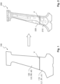
- the press-hardened sheet metal part 200 shown has two sheet metal part areas 210, 220 which are connected by a weld seam V.
- the sheet metal part areas 210, 220 differ in their strengths and corrosion protection properties.
- the sheet metal part 200 is a side wall pillar (more precisely, a B-pillar reinforcement) for a motor vehicle body, wherein the first sheet metal part area 210 forms the so-called pillar foot (foot area) and the second sheet metal part area 220 forms the pillar center (middle area) and the pillar roof connection (head area).
- the press-hardened sheet metal part 200 is produced in one piece from the Fig.1
- the tailored welded blank 100 shown is produced (as described above).
- the tailored welded blank 100 has a first sheet metal piece 110 from which the first sheet metal part region 210 is formed, and a second sheet metal piece 120 from which the second sheet metal part region 220 is formed.
- the two sheet metal pieces 110, 120 are welded together along a weld seam V.
- the first sheet metal piece 110 is made from a first steel alloy L1 (e.g. 22 MnB5) and has a first metallic protective coating B1, which is in particular a zinc-containing alloy.
- the second sheet metal piece 120 is made from a second steel alloy L2 (e.g. 34MnB5) and has a second metallic protective coating B2, which is also in particular a zinc-containing alloy.
- the second sheet metal piece 120 is thinner than the first sheet metal piece 110, i.e. h, the (homogeneous) sheet thickness s1 of the first sheet piece 110 is greater than the (homogeneous) sheet thickness s2 of the second sheet piece 120.
- the sheet thickness s1 is, for example, 1.8 mm to 3.0 mm and the sheet thickness s2 is, for example, 1.5 mm to 2.5 mm.)
- these sheet thicknesses are essentially retained.
- the second steel alloy L2 differs from the first steel alloy L1 at least in that it develops a higher strength during press hardening, so that (after press hardening) the second sheet metal part region 220 has a higher strength ( ⁇ 1750 MPa) than the first sheet metal part region 210 ( ⁇ 1650 MPa), whereby conversely the first sheet metal part region 210 has a higher ductility than the second sheet metal part region 220.
- the different strength and ductility properties enable a load-appropriate design of the sheet metal part or the side wall pillar 200, in particular with regard to crash behavior.
- the first metallic protective coating B1 of the first sheet metal piece 110 is thicker than the second metallic protective coating B2 of the second sheet metal piece 120, which is why the metallic protective coatings B1 and B2 behave and change differently during heating and press hardening.
- the second metallic protective coating B2 is preferably so thin (with a layer thickness ⁇ 10 ⁇ m) that it only functions as an anti-scale coating during heating and press hardening (as described above), so that then (after heating and press hardening) the corrosion protection effect in the second sheet metal part region 220 is rather low or lower (in particular in comparison to the corrosion protection effect in the first sheet metal part region 210).
- the first metallic protective coating B1 is preferably so thick (with a layer thickness ⁇ 11 ⁇ m) that after heating and press hardening in the first sheet metal part region 210, a high or higher corrosion protection effect is achieved (in particular in comparison to the corrosion protection effect in the second sheet metal part region 220), so that this sheet metal part region 210 can also be used, for example, in a so-called wet zone (wet area).
- the thin metallic protective coating B2 of the second sheet metal piece 120 also reduces the risk of embrittlement.
- a thicker metallic protective coating of the second sheet metal piece 120 e.g. as on the first sheet metal piece 110
- a lower corrosion protection effect is deliberately accepted in order to reduce the risk of embrittlement or to avoid embrittlement of the second (high-strength) sheet metal part area 220.
- this is acceptable because the second sheet metal part area 220 (in contrast to the first sheet metal part area 210) is not in a wet zone, but in a zone with lower corrosion protection requirements.
- the invention also enables adaptation to different corrosion protection requirements.
Landscapes
- Chemical & Material Sciences (AREA)
- Engineering & Computer Science (AREA)
- Mechanical Engineering (AREA)
- Materials Engineering (AREA)
- Metallurgy (AREA)
- Organic Chemistry (AREA)
- Thermal Sciences (AREA)
- Physics & Mathematics (AREA)
- Crystallography & Structural Chemistry (AREA)
- Chemical Kinetics & Catalysis (AREA)
- Combustion & Propulsion (AREA)
- Transportation (AREA)
- Heat Treatment Of Articles (AREA)
Description
- Die Erfindung betrifft ein Verfahren zur Herstellung eines pressgehärteten Blechformteils mit bereichsweise unterschiedlichen Eigenschaften.
- Beim Presshärten wird ein presshärtegeeignetes und auf Austenitisierungstemperatur erwärmtes Stahlblechmaterial in einem Presshärtewerkzeug geformt und abschreckgekühlt, wodurch sich bekanntermaßen hohe Festigkeiten erzielen lassen. Als Ausgangsplatinen für das Presshärten können auch sogenannte Tailored Welded Blanks (TWB) verwendet werden. Im Sinne der nachfolgend erläuterten Erfindung ist mit "Tailored Welded Blank" eine aus mehreren (wenigstens zwei) miteinander verschweißten Blechstücken bzw. Teilplatinen gebildete Stahlblechplatine gemeint.
- Die Patentschrift
KR 2015 0117585 A - Die Patentschrift
DE 10 2017 110 864 B3 beschreibt ein Verfahren zum Erzeugen gehärteter Stahlblechbauteile aus miteinander verschweißten Blechen unterschiedlicher Blechdicke und/oder unterschiedlicher Blechmaterialien. Der dickere Bereich kann eine Zink-Eisen-Beschichtung besitzen, während der dünnere Bereich eine Zink-Beschichtung besitzt. - Das Presshärten von Tailored Welded Blanks ist ferner in den Patentschriften
EP 2 289 770 A1 undUS 2014/0154521 A1 beschrieben. - Mit der Erfindung wird ein neues Verfahren mit den im Patentanspruch 1 genannten Schritten zur Herstellung eines pressgehärteten Blechformteils mit bereichsweise unterschiedlichen Eigenschaften vorgestellt. Zusätzliche Merkmale der Erfindung ergeben sich aus den abhängigen Patentansprüchen, der nachfolgenden Erfindungsbeschreibung (wobei dies ausdrücklich auch Merkmale einschließt, die als "beispielsweise", "bevorzugt", "insbesondere" etc. beschrieben sind) und der Zeichnung.
- Das erfindungsgemäße Verfahren zur Herstellung eines pressgehärteten Blechformteils mit partiell bzw. bereichsweise unterschiedlichen Eigenschaften weist folgende Schritte auf:
- Bereitstellen einer (vorgefertigten) Tailored Welded Blank, mit einem ersten Blechstück, welches aus einer ersten (presshärtbaren) Stahllegierung gebildet ist und eine erste metallische Schutzbeschichtung aufweist, und mit einem zweiten Blechstück, welches aus einer zweiten (presshärtbaren) Stahlegierung gebildet ist und eine zweite metallische Schutzbeschichtung aufweist, wobei die metallischen Schutzbeschichtungen unterschiedliche Schichtdicken aufweisen, womit gemeint ist, dass die erste metallische Schutzbeschichtung und die zweite metallische Schutzbeschichtung mit unterschiedlichen Schichtdicken aufgetragen bzw. ausgebildet sind;
- Erwärmen (typischerweise auf eine einheitliche Temperatur > 850°C, sodass eine Austenitisierung erfolgt), Umformen und Presshärten der Tailored Welded Blank (sogenanntes direktes Presshärten, wobei das Umformen und Presshärten im Presshärtewerkzeug erfolgt) oder Umformen, Erwärmen (s. o.) und Presshärten der Tailored Welded Blank (sogenanntes indirektes Presshärten), wodurch ein pressgehärtetes, insbesondere ein vollständig (nicht nur partiell) pressgehärtetes, Blechformteil erzeugt wird, das einen aus dem ersten Blechstück gebildeten (pressgehärteten) ersten Blechformteilbereich und einen aus dem zweiten Blechstück gebildeten (pressgehärteten) zweiten Blechformteilbereich aufweist, wobei sich diese beiden Blechformteilbereiche in ihren Festigkeiten und Korrosionsschutzeigenschaften voneinander unterscheiden, womit gemeint ist, dass der aus dem ersten Blechstück gebildete erste Blechformteilbereich eine andere Festigkeit und Korrosionsschutzeigenschaft aufweist als der aus dem zweiten Blechstück gebildete zweite Blechformteilbereich.
- Mit Festigkeit ist insbesondere die durch das Presshärten erzielte Zugfestigkeit des Stahlblechmaterials gemeint. Mit Korrosionsschutzeigenschaft ist insbesondere die durch die jeweilige metallische Schutzbeschichtung erzielte Schutzeigenschaft bzw. Schutzwirkung zur Vermeidung oder Verringerung von Korrosionsschäden am pressgehärteten Stahlblechmaterial gemeint, wobei diese Schutzwirkung mehr oder weniger stark ausgeprägt ist, wie nachfolgend noch näher erläutert.
- Das erfindungsgemäße Verfahren ermöglicht neue Wege bei der Gestaltung und Herstellung pressgehärteter Blechformteile mit besonderen Eigenschaften. Mit dem erfindungsgemäßen Verfahren kann bspw. ein pressgehärtetes Blechformteil hergestellt werden, das einen besonders festen bzw. hochfesten Blechformteilbereich mit vergleichsweise geringer Korrosionsschutzwirkung und einen (nur) festen Blechformteilbereich mit vergleichsweise hoher und somit nassbereichtauglicher Korrosionsschutzwirkung aufweist. Durch Einsatz unterschiedlicher Blechdicken (s. u.) gelingt ferner auch eine Gewichtsoptimierung.
- Die erste Stahllegierung (des ersten Blechstücks) und die zweite Stahllegierung (des zweiten Blechstücks) sind unterschiedlich, sodass beim Presshärten unterschiedliche Festigkeiten erreicht werden, was insbesondere durch einen unterschiedlichen Kohlenstoffgehalt bzw. -anteil in den Stahllegierungen erreicht wird. Die zweite Stahllegierung unterscheidet sich von der ersten Stahllegierung darin, dass diese beim Presshärten materialbedingt eine höhere Festigkeit ausbildet, sodass (nach dem Presshärten) der zweite Blechformteilbereich eine höhere Festigkeit sowie gegebenenfalls eine geringere Duktilität aufweist als der erste Blechformteilbereich. Es ist vorgesehen, dass der erste (pressgehärtete) Blechformteilbereich eine Festigkeit von ≤ 1650 MPa, insbesondere zwischen 1350 MPa und 1650 MPa, aufweist und dass der zweite (pressgehärtete) Blechformteilbereich eine Festigkeit von ≥ 1750 MPa, insbesondere zwischen 1750 MPa und 2000 MPa, aufweist und somit hochfest ist.
- Die zweite metallische Schutzbeschichtung (auf dem zweiten Blechstück) ist dünner ausgebildet als die erste metallische Schutzbeschichtung (auf dem ersten Blechstück). Sowohl die erste metallische Schutzbeschichtung als auch die zweite metallische Schutzbeschichtung sind aus einer zinkhaltigen Legierung, insbesondere aus derselben zinkhaltigen Legierung, gebildet, wobei die erste metallische Schutzbeschichtung bzw. Zinkbeschichtung (vor dem Erwärmen und Presshärten) eine Schichtdicke von ≥ 11 µm und die zweite metallische Schutzbeschichtung bzw. Zinkbeschichtung eine Schichtdicke von ≤ 10 µm, aufweist. Beim Erwärmen steigt der Eisengehalt in der dünneren zweiten metallischen Schutzbeschichtung bzw. Zinkbeschichtung so stark an, dass diese zweite Schutzbeschichtung am pressgehärteten Blechformteil nur eine geringe Korrosionsschutzwirkung bietet. Die dünnere zweite metallische Schutzbeschichtung bzw. Zinkbeschichtung fungiert somit quasi nur als Zunderschutzbeschichtung für das Erwärmen und Presshärten. Durch die geringe Schicht- bzw. Zinkauflagendicke wird jedoch beim Erwärmen und Presshärten die Versprödungsgefahr (Liquid Metal Embrittlement) reduziert, sodass sehr hohe Festigkeiten von bspw. > 1650 MPa (die sonst aufgrund der Versprödungsgefahr nicht möglich sind) erreicht werden können. Beim Erwärmen steigt auch in der dickeren ersten metallischen Schutzbeschichtung bzw. Zinkbeschichtung der Eisengehalt an, dies jedoch nur in einem verhältnismäßig geringen Maße, sodass diese erste metallische Schutzbeschichtung am pressgehärteten Blechformteil eine hohe, insbesondere auch nassbereichtaugliche, Korrosionsschutzwirkung bietet. Die dickere erste metallische Schutzbeschichtung bzw. Zinkbeschichtung fungiert somit quasi als Korrosionsschutzbeschichtung.
- Dass sich die Blechformteilbereiche in ihren Korrosionsschutzeigenschaften bzw. in der jeweils erzielten Korrosionsschutzwirkung voneinander unterscheiden ist also insbesondere so zu verstehen, dass nach dem Erwärmen und Presshärten die metallische Schutzbeschichtung des ersten Blechformteilbereichs dicker ausgebildet ist bzw. eine größere Schichtdicke aufweist sowie auch einen geringeren Eisengehalt (womit insbesondere der prozentuale Eisenanteil gemeint ist) aufweist als die metallische Schutzbeschichtung des zweiten Blechformteilbereichs (und umgekehrt).
- Beide metallischen Schutzbeschichtungen sind bevorzugt vollflächig und beidseitig, insbesondere durch ein Schmelztauchverfahren oder eventuell auch durch Gasphasenabscheidung (PVD), aufgebracht. (Die metallischen Schutzbeschichtungen werden bevorzugt bereits auf die Blechbänder aufgebracht, aus denen dann die Blechstücke angefertigt werden.)
- Bevorzugt weist das erste Blechstück der Welded Tailored Blank eine andere Blechdicke als das zweite Blechstück auf, wobei sich die Blechdicken der Blechstücke insbesondere um wenigstens 0,2 mm unterscheiden. Damit ist gemeint, dass das erste Blechstück eine erste Blechdicke und das zweite Blechstück eine zweite Blechdicke aufweist, wobei sich die erste und zweite Blechdicke voneinander unterscheiden, insbesondere um wenigstens 0,2 mm. Bevorzugt ist das zweite Blechstück, welches insbesondere beim Presshärten eine höhere Festigkeit als das erste Blechstück erreicht, dünner, insbesondere um wenigstens 0,2 mm dünner als das erste Blechstück ausgebildet. Durch die unterschiedlichen Blechdicken gelingt eine belastungsgerechte Gewichtsoptimierung.
- Zwischen dem Erwärmen und Presshärten kann ein Zwischenkühlen (auch als Vorkühlen bezeichnet) erfolgen, wobei eine solches Zwischenkühlen insbesondere für das direkte Presshärten (s. o.) vorgesehen ist. Damit ist gemeint, dass das erwärmte und austenitisierte Stahlblechmaterial, insbesondere die erwärmte und austenitisierte Tailored Welded Blank, vor dem Presshärten, also vor dem Einlegen in das Presshärtewerkzeug, zumindest bereichsweise bzw. partiell gekühlt wird, insbesondere auf eine Temperatur ≤ 650°C. Durch das Zwischenkühlen kann die Versprödungsgefahr (s. o.) verringert werden. Das Zwischenkühlen kann aktiv sowohl ein- als auch beidseitig mittels Luftdüsen, Kühlwalzen oder Kühlplatten erfolgen. Bevorzugt ist eine vollständige gleichmäßige Zwischenkühlung vorgesehen. Das Zwischenkühlen kann jedoch auch nur bereichsweise erfolgen, insbesondere nur für das erste Blechstück oder nur für das zweite Blechstück. Außerdem kann vorgesehen sein, dass bereichsweise eine unterschiedliche Zwischenkühlung erfolgt, insbesondere derart, dass das zweite Blechstück auf eine andere Temperatur als erste Blechstück gekühlt wird.
- Die Tailored Welded Blank kann durch Aufbringen wenigstens eines zusätzlichen Blechstücks (auch als Patchblech bezeichnet) lokal verstärkt werden, welches dann quasi mit pressgehärtet wird, sodass das pressgehärtete Blechformteil an der betreffenden Stelle bzw. im betreffenden Bereich lokal höheren Festigkeits- und/oder Steifigkeitsanforderungen genügt. Das zusätzliche Blechstück kann an der betreffenden Stelle bzw. im betreffenden Bereich auf die Tailored Welded Blank aufgeschweißt oder auch aufgelötet werden. Grundsätzlich kann ein zusätzliches Blechstück auf dem ersten Blechstück oder auf dem zweiten Blechstück der Tailored Welded Blank angeordnet werden, wobei auch eine überlappende Anordnung möglich ist. Bevorzugt ist vorgesehen, dass ein auf dem ersten Blechstück anzuordnendes zusätzliches Blechstück aus derselben ersten Stahllegierung wie das erste Blechstück gebildet ist und insbesondere auch eine metallische Schutzbeschichtung aufweist, deren Legierungszusammensetzung und/oder Schichtdicke der ersten metallischen Schutzbeschichtung des ersten Blechstücks entspricht. Bevorzugt gilt selbiges analog für ein auf dem zweiten Blechstück anzuordnendes zusätzliches Blechstück. Das Aufbringen wenigstens eines zusätzlichen Blechstücks auf die Tailored Welded Blank kann unmittelbar vor dem Erwärmen und (direkten) Pressehärten erfolgen. Ebenso kann die bereitgestellte (vorgefertigte) Tailored Welded Blank bereits wenigstens ein solches zusätzliches Blechstück aufweisen.
- Ein mit dem erfindungsgemäßen Verfahren hergestelltes pressgehärtetes Blechformteil ist aus einer einzelnen Tailored Welded Blank hergestellt und weist einen aus einem ersten Blechstück der Tailored Welded Blank gebildeten ersten Blechformteilbereich sowie einen aus einem zweiten Blechstück der Tailored Welded Blank gebildeten zweiten Blechformteilbereich auf, wobei sich diese beiden Blechformteilbereiche in ihren Festigkeiten und Korrosionsschutzeigenschaften voneinander unterscheiden. Bevorzugt handelt es sich um ein Karosserie- oder Fahrwerkverstärkungsbauteil, insbesondere um eine sogenannte Säulen-Verstärkung für die Karosserieseitenwand. Die Erfindung ermöglicht also die Herstellung eines pressgehärteten Blechformteils aus einer einzelnen Tailored Welded Blank, welches bereichsweise bzw. partiell unterschiedliche Festigkeits- und Korrosionsschutzanforderungen erfüllt.
- Die Erfindung wird nachfolgend mit Bezug auf die Zeichnung anhand eines bevorzugten Ausführungsbeispiels näher erläutert.
- Fig. 1
- zeigt eine ebene Tailored Welded Blank im Ausgangszustand zur Herstellung eines pressgehärteten Blechformteils.
- Fig. 2
- zeigt das aus der Tailored Welded Blank der
Fig. 1 hergestellte pressgehärtete Blechformteil. - Das in
Fig. 2 gezeigte pressgehärtete Blechformteil 200 weist zwei Blechformteilbereiche 210, 220 auf, die durch eine Schweißnaht V verbunden sind. Die Blechformteilbereiche 210, 220 unterscheiden sich in ihren Festigkeiten und Korrosionsschutzeigenschaften. Bei dem Blechformteil 200 handelt es sich um eine Seitenwandsäule (genau genommen um eine B-Säulen-Verstärkung) für eine Kraftfahrzeugkarosserie, wobei der erste Blechformteilbereich 210 den sogenannten Säulenfuß (Fußbereich) bildet und der zweite Blechformteilbereich 220 die Säulenmitte (Mittelbereich) und die Säulendachanbindung (Kopfbereich) bildet. - Das pressgehärtete Blechformteil 200 wird in einem Stück aus der in
Fig. 1 gezeigten Tailored Welded Blank 100 hergestellt (wie oben beschrieben). Die Tailored Welded Blank 100 weist ein erstes Blechstück 110 auf, aus dem der erste Blechformteilbereich 210 gebildet wird, und ein zweites Blechstück 120, aus dem der zweite Blechformteilbereich 220 gebildet wird. Die beiden Blechstücke 110, 120 sind entlang einer Schweißnaht V miteinander verschweißt. - Das erste Blechstück 110 ist aus einer ersten Stahllegierung L1 (bspw. 22 MnB5) gebildet und weist eine erste metallische Schutzbeschichtung B1 auf, wobei es sich insbesondere um eine zinkhaltige Legierung handelt. Das zweite Blechstück 120 ist aus einer zweiten Stahllegierung L2 (bspw. 34MnB5) gebildet und weist eine zweite metallische Schutzbeschichtung B2 auf, wobei es sich auch hierbei insbesondere um eine zinkhaltige Legierung handelt. Außerdem ist das zweite Blechstück 120 dünner ausgebildet ist als das erste Blechstück 110, d. h, die (homogene) Blechdicke s1 des ersten Blechstücks 110 ist größer als die (homogene) Blechdicke s2 des zweiten Blechstücks 120. (Die Blechdicke s1 beträgt bspw. 1,8 mm bis 3,0 mm und die Blechdicke s2 bspw. 1,5 mm bis 2,5 mm.) Beim Presshärten bleiben diese Blechdicken im Wesentlichen erhalten.
- Die zweite Stahllegierung L2 unterscheidet sich zur ersten Stahllegierung L1 zumindest darin, dass diese beim Presshärten eine höhere Festigkeit ausbildet, sodass (nach dem Presshärten) der zweite Blechformteilbereich 220 eine höhere Festigkeit aufweist (≥ 1750 MPa) als der erste Blechformteilbereich 210 (≤ 1650 MPa), wobei umgekehrt der erste Blechformteilbereich 210 eine höhere Duktilität als der zweite Blechformteilbereich 220 aufweist. Durch die unterschiedlichen Festigkeits- und Duktilitätseigenschaften gelingt eine belastungsgerechte Auslegung des Blechformteils bzw. der Seitenwandsäule 200, insbesondere in Hinblick auf das Crashverhalten.
- Ferner ist vorgesehen, dass die erste metallische Schutzbeschichtung B1 des ersten Blechstücks 110 dicker ausgebildet ist als die zweite metallische Schutzbeschichtung B2 des zweiten Blechstücks 120, weshalb sich die metallischen Schutzbeschichtungen B1 und B2 beim Erwärmen und Presshärten unterschiedlich verhalten und verändern. Die zweite metallische Schutzbeschichtung B2 ist bevorzugt so dünn ausgebildet (mit einer Schichtdicke ≤ 10 µm), dass diese beim Erwärmen und Presshärten lediglich als Zunderschutzbeschichtung fungiert (wie oben beschrieben), sodass dann (nach dem Erwärmen und Presshärten) die Korrosionsschutzwirkung im zweiten Blechformteilbereich 220 eher gering bzw. geringer ist (insbesondere im Vergleich zur Korrosionsschutzwirkung im ersten Blechformteilbereich 210). Hingegen ist die erste metallische Schutzbeschichtung B1 bevorzugt so dick ausgebildet (mit einer Schichtdicke ≥ 11 µm), dass nach dem Erwärmen und Presshärten im ersten Blechformteilbereich 210 eine hohe bzw. höhere Korrosionsschutzwirkung erreicht wird (insbesondere im Vergleich zur Korrosionsschutzwirkung im zweiten Blechformteilbereich 220), sodass dieser Blechformteilbereich 210 bspw. auch in einer sogenannten Nasszone (Nassbereich) eingesetzt werden kann.
- Die dünne metallische Schutzbeschichtung B2 des zweiten Blechstücks 120 verringert außerdem die Versprödungsgefahr. Eine dickere metallische Schutzbeschichtung des zweiten Blechstücks 120 (bspw. wie auf dem ersten Blechstück 110) würde eine Versprödung des besonders festen bzw. hochfesten zweiten Blechformteilbereichs 220 begünstigen. So gesehen wird zur Verringerung der Versprödungsgefahr bzw. zur Vermeidung einer Versprödung des zweiten (hochfesten) Blechformteilbereichs 220 bewusst eine niedrigere Korrosionsschutzwirkung in Kauf genommen. Für den beschriebenen Anwendungsfall (Seitenwandsäule bzw. Säulen-Verstärkung) ist dies hinnehmbar, da sich der zweite Blechformteilbereich 220 (im Gegensatz zum ersten Blechformteilbereich 210) nicht in einer Nasszone befindet, sondern in einer Zone mit geringerer Korrosionsschutzanforderung. Die Erfindung ermöglicht also auch eine Anpassung an unterschiedliche Korrosionsschutzanforderungen.
-
- 100
- Tailored Welded Blank
- 110
- erstes Blechstück (erste Teilplatine)
- 120
- zweites Blechstück (zweite Teilplatine)
- 200
- pressgehärtetes Blechformteil
- 210
- erster Blechformteilbereich
- 220
- zweiter Blechformteilbereich
- B1
- erste metallische Schutzbeschichtung
- B2
- zweite metallische Schutzbeschichtung
- L1
- erste Stahllegierung
- L2
- zweite Stahllegierung
- s1
- Blechdicke
- s2
- Blechdicke
- V
- Schweißnaht
Claims (5)
- Verfahren zur Herstellung eines pressgehärteten Blechformteils (200) mit bereichsweise unterschiedlichen Eigenschaften, umfassend die Schritte:- Bereitstellen einer Tailored Welded Blank (100), mit einem ersten Blechstück (110), welches aus einer ersten Stahllegierung (L1) gebildet ist und eine erste metallische Schutzbeschichtung (B1) aufweist, und mit einem zweiten Blechstück (120), welches aus einer zweiten Stahllegierung (L2) gebildet ist und eine zweite metallische Schutzbeschichtung (B2) aufweist,wobei sich die zweite Stahllegierung (L2) von der ersten Stahllegierung (L1) darin unterscheidet, dass diese beim Presshärten materialbedingt eine höhere Festigkeit ausbildet,wobei sowohl die erste metallische Schutzbeschichtung (B1) als auch die zweite metallische Schutzbeschichtung (B2) aus einer zinkhaltigen Legierung gebildet ist, wobei die erste metallische Schutzbeschichtung (B1) eine Schichtdicke von ≥ 11 µm und die zweite metallische Schutzbeschichtung (B2) eine Schichtdicke von ≤ 10 µm aufweist;- Erwärmen, Umformen und Presshärten oder Umformen, Erwärmen und Presshärten der Tailored Welded Blank (100), wodurch ein pressgehärtetes Blechformteil (200) erzeugt wird, das einen aus dem ersten Blechstück (110) gebildeten ersten Blechformteilbereich (210) und einen aus dem zweiten Blechstück (120) gebildeten zweiten Blechformteilbereich (220) aufweist,wobei sich diese beiden Blechformteilbereiche (210, 220) in ihren Festigkeiten voneinander unterscheiden, derart, dass der erste Blechformteilbereich (210) eine Festigkeit von ≤ 1650 MPa und der zweite Blechformteilbereich (220) eine Festigkeit ≥ 1750 MPa aufweist, undwobei sich diese beiden Blechformteilbereiche (210, 220) auch in ihren Korrosionsschutzeigenschaften voneinander unterscheiden.
- Verfahren nach Anspruch 1,
dadurch gekennzeichnet, dass
das erste Blechstück (110) eine andere Blechdicke als das zweite Blechstück (120) aufweist. - Verfahren nach einem der vorhergehenden Ansprüche,
dadurch gekennzeichnet, dass
zwischen dem Erwärmen und Presshärten ein zumindest partielles Zwischenkühlen vorgesehen ist. - Verfahren nach einem der vorhergehenden Ansprüche,
dadurch gekennzeichnet, dass
die Tailored Welded Blank (100) durch Aufbringen wenigstens eines zusätzlichen Blechstücks lokal verstärkt wird. - Verfahren nach einem der vorhergehenden Ansprüche,
dadurch gekennzeichnet, dass
das hergestellte pressgehärtete Blechformteil (200) eine Säulen-Verstärkung für eine Karosserieseitenwand ist, wobei der erste Blechformteilbereich (210) den Säulenfuß bildet und der zweite Blechformteilbereich (220) die Säulenmitte und die Säulendachanbindung bildet.
Applications Claiming Priority (1)
| Application Number | Priority Date | Filing Date | Title |
|---|---|---|---|
| DE102021201334.1A DE102021201334A1 (de) | 2021-02-12 | 2021-02-12 | Verfahren zur Herstellung eines pressgehärteten Blechformteils sowie damit hergestelltes pressgehärtetes Blechformteil mit bereichsweise unterschiedlichen Eigenschaften |
Publications (2)
| Publication Number | Publication Date |
|---|---|
| EP4043115A1 EP4043115A1 (de) | 2022-08-17 |
| EP4043115B1 true EP4043115B1 (de) | 2024-08-21 |
Family
ID=80119537
Family Applications (1)
| Application Number | Title | Priority Date | Filing Date |
|---|---|---|---|
| EP22154682.3A Active EP4043115B1 (de) | 2021-02-12 | 2022-02-02 | Verfahren zur herstellung eines pressgehärteten blechformteils mit bereichsweise unterschiedlichen eigenschaften |
Country Status (2)
| Country | Link |
|---|---|
| EP (1) | EP4043115B1 (de) |
| DE (1) | DE102021201334A1 (de) |
Families Citing this family (2)
| Publication number | Priority date | Publication date | Assignee | Title |
|---|---|---|---|---|
| CN115555804A (zh) * | 2022-09-30 | 2023-01-03 | 重庆至信实业集团有限公司 | 一种汽车门柱拼焊方法及模具 |
| DE102023113543A1 (de) | 2023-05-24 | 2024-11-28 | Audi Aktiengesellschaft | Karosserieelement, Kraftfahrzeugkarosserie, Kraftfahrzeug sowie Verfahren zur Herstellung eines Karosserieelements |
Family Cites Families (6)
| Publication number | Priority date | Publication date | Assignee | Title |
|---|---|---|---|---|
| EP2289770A1 (de) | 2009-08-28 | 2011-03-02 | ThyssenKrupp Steel Europe AG | Korrosiongeschützte geschweisste Blechplatine für ein Kraftfahrzeug und deren Herstellungsverfahren |
| KR101448473B1 (ko) | 2012-12-03 | 2014-10-10 | 현대하이스코 주식회사 | 테일러 웰디드 블랭크, 그 제조방법 및 이를 이용한 핫스탬핑 부품 |
| KR20150117585A (ko) * | 2014-04-10 | 2015-10-20 | 주식회사 신영 | 이종소재 twb 및 핫스탬핑을 적용한 센터필러 제조방법, 및 이에 의해 제조된 센터필러 |
| DE102017110864B3 (de) * | 2017-05-18 | 2018-10-18 | Voestalpine Metal Forming Gmbh | Verfahren und Vorrichtung zum Erzeugen gehärteter Stahlblechbauteile mit unterschiedlichen Blechdicken |
| DE102018200843A1 (de) | 2018-01-19 | 2019-07-25 | Bayerische Motoren Werke Aktiengesellschaft | Verfahren und Aufheizvorrichtung zum Aufheizen eines Werkstücks zum Herstellen eines Bauteils, insbesondere für ein Kraftfahrzeug |
| WO2019245025A1 (ja) * | 2018-06-22 | 2019-12-26 | 日本製鉄株式会社 | 鋼板、テーラードブランク、熱間プレス成形品、鋼管、中空状焼入れ成形品、及び鋼板の製造方法 |
-
2021
- 2021-02-12 DE DE102021201334.1A patent/DE102021201334A1/de active Pending
-
2022
- 2022-02-02 EP EP22154682.3A patent/EP4043115B1/de active Active
Also Published As
| Publication number | Publication date |
|---|---|
| DE102021201334A1 (de) | 2022-08-18 |
| EP4043115A1 (de) | 2022-08-17 |
Similar Documents
| Publication | Publication Date | Title |
|---|---|---|
| EP2553133B1 (de) | Stahl, stahlflachprodukt, stahlbauteil und verfahren zur herstellung eines stahlbauteils | |
| EP3265365B1 (de) | Pressgehärtetes blechformteil mit unterschiedlichen blechdicken und festigkeiten | |
| EP3004401B1 (de) | Verfahren zur herstellung eines bauteils durch warmumformen eines vorproduktes aus stahl | |
| EP1651789A1 (de) | Verfahren zum herstellen von geh rteten bauteilen aus stahlblech | |
| DE102015112327A1 (de) | Karosserie- oder Fahrwerkbauteil eines Kraftfahrzeuges mit verbesserter Crashperformance sowie Verfahren zu dessen Herstellung | |
| EP4223889B1 (de) | Verfahren zur herstellung eines mit einem metallischen, vor korrosion schützenden überzug versehenen stahlbauteils | |
| EP3724359B1 (de) | Hochfestes, warmgewalztes stahlflachprodukt mit hohem kantenrisswiderstand und gleichzeitig hohem bake-hardening potential und verfahren zur herstellung eines solchen stahlflachprodukts | |
| EP1939308A1 (de) | Verfahren zum Herstellen eines Bauteils durch Wärmepresshärten und hochfestes Bauteil mit verbesserter Bruchdehnung | |
| DE102010049205A1 (de) | Warmumformlinie und Verfahren zum Warmumformen von blechförmigem Material | |
| WO2019185272A1 (de) | VERFAHREN ZUM SCHWEIßEN BESCHICHTETER STAHLBLECHE | |
| EP1263540B1 (de) | Verfahren zur herstellung von dünnwandigen bauteilen aus stahl und danach hergestellte bauteile | |
| WO2018210574A1 (de) | DREILAGIGER VERSCHLEIßSTAHL ODER SICHERHEITSSTAHL, VERFAHREN ZUR HERSTELLUNG EINER KOMPONENTE UND VERWENDUNG | |
| EP3827103B1 (de) | Verfahren zur herstellung eines gehärteten stahlprodukts | |
| WO2011023499A1 (de) | Korrosionsgeschützte geschweisste blechplatine für ein kraftfahrzeug und deren herstellungsverfahren | |
| EP4043115A1 (de) | Verfahren zur herstellung eines pressgehärteten blechformteils sowie damit hergestelltes pressgehärtetes blechformteil mit bereichsweise unterschiedlichen eigenschaften | |
| EP3625045B1 (de) | Warmumformmaterial, bauteil und verwendung | |
| EP3625044B1 (de) | Warmumformmaterial, bauteil und verwendung | |
| EP3976842B1 (de) | Verfahren zur herstellung eines geschweissten bauteils aus einem umgeformten hochfesten stahl | |
| EP3430180B1 (de) | Verfahren zur herstellung eines warmumgeformten stahlbauteils | |
| DE102009049398B3 (de) | Verfahren zur Herstellung eines Strukturbauteils für ein Kraftfahrzeug, Platine für die Warmumformung und Strukturbauteil | |
| EP3352927A1 (de) | Halbzeug und verfahren zur herstellung einer fahrzeugkomponente, verwendung eines halbzeugs und fahrzeugkomponente | |
| DE102004053258B4 (de) | Längsträger für eine Fahrzeugkarosserie | |
| DE102015221635A1 (de) | Pressgehärtetes Blechformteil mit unterschiedlichen Blechdicken und Festigkeiten | |
| DE102019130381A1 (de) | Kraftfahrzeugbauteil mit gesteigerter Festigkeit | |
| EP4168597B1 (de) | Verfahren zum herstellen eines stahlflachprodukts, stahlflachprodukt und verwendung eines solchen stahlflachprodukts |
Legal Events
| Date | Code | Title | Description |
|---|---|---|---|
| PUAI | Public reference made under article 153(3) epc to a published international application that has entered the european phase |
Free format text: ORIGINAL CODE: 0009012 |
|
| STAA | Information on the status of an ep patent application or granted ep patent |
Free format text: STATUS: THE APPLICATION HAS BEEN PUBLISHED |
|
| AK | Designated contracting states |
Kind code of ref document: A1 Designated state(s): AL AT BE BG CH CY CZ DE DK EE ES FI FR GB GR HR HU IE IS IT LI LT LU LV MC MK MT NL NO PL PT RO RS SE SI SK SM TR |
|
| STAA | Information on the status of an ep patent application or granted ep patent |
Free format text: STATUS: REQUEST FOR EXAMINATION WAS MADE |
|
| TPAC | Observations filed by third parties |
Free format text: ORIGINAL CODE: EPIDOSNTIPA |
|
| 17P | Request for examination filed |
Effective date: 20230217 |
|
| RBV | Designated contracting states (corrected) |
Designated state(s): AL AT BE BG CH CY CZ DE DK EE ES FI FR GB GR HR HU IE IS IT LI LT LU LV MC MK MT NL NO PL PT RO RS SE SI SK SM TR |
|
| STAA | Information on the status of an ep patent application or granted ep patent |
Free format text: STATUS: EXAMINATION IS IN PROGRESS |
|
| 17Q | First examination report despatched |
Effective date: 20230616 |
|
| GRAP | Despatch of communication of intention to grant a patent |
Free format text: ORIGINAL CODE: EPIDOSNIGR1 |
|
| STAA | Information on the status of an ep patent application or granted ep patent |
Free format text: STATUS: GRANT OF PATENT IS INTENDED |
|
| INTG | Intention to grant announced |
Effective date: 20240313 |
|
| GRAS | Grant fee paid |
Free format text: ORIGINAL CODE: EPIDOSNIGR3 |
|
| GRAA | (expected) grant |
Free format text: ORIGINAL CODE: 0009210 |
|
| STAA | Information on the status of an ep patent application or granted ep patent |
Free format text: STATUS: THE PATENT HAS BEEN GRANTED |
|
| P01 | Opt-out of the competence of the unified patent court (upc) registered |
Free format text: CASE NUMBER: APP_40206/2024 Effective date: 20240705 |
|
| AK | Designated contracting states |
Kind code of ref document: B1 Designated state(s): AL AT BE BG CH CY CZ DE DK EE ES FI FR GB GR HR HU IE IS IT LI LT LU LV MC MK MT NL NO PL PT RO RS SE SI SK SM TR |
|
| REG | Reference to a national code |
Ref country code: GB Ref legal event code: FG4D Free format text: NOT ENGLISH |
|
| REG | Reference to a national code |
Ref country code: CH Ref legal event code: EP |
|
| REG | Reference to a national code |
Ref country code: DE Ref legal event code: R096 Ref document number: 502022001484 Country of ref document: DE |
|
| REG | Reference to a national code |
Ref country code: IE Ref legal event code: FG4D Free format text: LANGUAGE OF EP DOCUMENT: GERMAN |
|
| REG | Reference to a national code |
Ref country code: LT Ref legal event code: MG9D |
|
| REG | Reference to a national code |
Ref country code: NL Ref legal event code: MP Effective date: 20240821 |
|
| PG25 | Lapsed in a contracting state [announced via postgrant information from national office to epo] |
Ref country code: NO Free format text: LAPSE BECAUSE OF FAILURE TO SUBMIT A TRANSLATION OF THE DESCRIPTION OR TO PAY THE FEE WITHIN THE PRESCRIBED TIME-LIMIT Effective date: 20241121 |
|
| PG25 | Lapsed in a contracting state [announced via postgrant information from national office to epo] |
Ref country code: NL Free format text: LAPSE BECAUSE OF FAILURE TO SUBMIT A TRANSLATION OF THE DESCRIPTION OR TO PAY THE FEE WITHIN THE PRESCRIBED TIME-LIMIT Effective date: 20240821 Ref country code: PT Free format text: LAPSE BECAUSE OF FAILURE TO SUBMIT A TRANSLATION OF THE DESCRIPTION OR TO PAY THE FEE WITHIN THE PRESCRIBED TIME-LIMIT Effective date: 20241223 Ref country code: PL Free format text: LAPSE BECAUSE OF FAILURE TO SUBMIT A TRANSLATION OF THE DESCRIPTION OR TO PAY THE FEE WITHIN THE PRESCRIBED TIME-LIMIT Effective date: 20240821 Ref country code: GR Free format text: LAPSE BECAUSE OF FAILURE TO SUBMIT A TRANSLATION OF THE DESCRIPTION OR TO PAY THE FEE WITHIN THE PRESCRIBED TIME-LIMIT Effective date: 20241122 Ref country code: FI Free format text: LAPSE BECAUSE OF FAILURE TO SUBMIT A TRANSLATION OF THE DESCRIPTION OR TO PAY THE FEE WITHIN THE PRESCRIBED TIME-LIMIT Effective date: 20240821 |
|
| PG25 | Lapsed in a contracting state [announced via postgrant information from national office to epo] |
Ref country code: BG Free format text: LAPSE BECAUSE OF FAILURE TO SUBMIT A TRANSLATION OF THE DESCRIPTION OR TO PAY THE FEE WITHIN THE PRESCRIBED TIME-LIMIT Effective date: 20240821 |
|
| PG25 | Lapsed in a contracting state [announced via postgrant information from national office to epo] |
Ref country code: LV Free format text: LAPSE BECAUSE OF FAILURE TO SUBMIT A TRANSLATION OF THE DESCRIPTION OR TO PAY THE FEE WITHIN THE PRESCRIBED TIME-LIMIT Effective date: 20240821 |
|
| PG25 | Lapsed in a contracting state [announced via postgrant information from national office to epo] |
Ref country code: IS Free format text: LAPSE BECAUSE OF FAILURE TO SUBMIT A TRANSLATION OF THE DESCRIPTION OR TO PAY THE FEE WITHIN THE PRESCRIBED TIME-LIMIT Effective date: 20241221 |
|
| PG25 | Lapsed in a contracting state [announced via postgrant information from national office to epo] |
Ref country code: HR Free format text: LAPSE BECAUSE OF FAILURE TO SUBMIT A TRANSLATION OF THE DESCRIPTION OR TO PAY THE FEE WITHIN THE PRESCRIBED TIME-LIMIT Effective date: 20240821 |
|
| PG25 | Lapsed in a contracting state [announced via postgrant information from national office to epo] |
Ref country code: ES Free format text: LAPSE BECAUSE OF FAILURE TO SUBMIT A TRANSLATION OF THE DESCRIPTION OR TO PAY THE FEE WITHIN THE PRESCRIBED TIME-LIMIT Effective date: 20240821 Ref country code: RS Free format text: LAPSE BECAUSE OF FAILURE TO SUBMIT A TRANSLATION OF THE DESCRIPTION OR TO PAY THE FEE WITHIN THE PRESCRIBED TIME-LIMIT Effective date: 20241121 |
|
| PG25 | Lapsed in a contracting state [announced via postgrant information from national office to epo] |
Ref country code: RS Free format text: LAPSE BECAUSE OF FAILURE TO SUBMIT A TRANSLATION OF THE DESCRIPTION OR TO PAY THE FEE WITHIN THE PRESCRIBED TIME-LIMIT Effective date: 20241121 Ref country code: PT Free format text: LAPSE BECAUSE OF FAILURE TO SUBMIT A TRANSLATION OF THE DESCRIPTION OR TO PAY THE FEE WITHIN THE PRESCRIBED TIME-LIMIT Effective date: 20241223 Ref country code: PL Free format text: LAPSE BECAUSE OF FAILURE TO SUBMIT A TRANSLATION OF THE DESCRIPTION OR TO PAY THE FEE WITHIN THE PRESCRIBED TIME-LIMIT Effective date: 20240821 Ref country code: NO Free format text: LAPSE BECAUSE OF FAILURE TO SUBMIT A TRANSLATION OF THE DESCRIPTION OR TO PAY THE FEE WITHIN THE PRESCRIBED TIME-LIMIT Effective date: 20241121 Ref country code: NL Free format text: LAPSE BECAUSE OF FAILURE TO SUBMIT A TRANSLATION OF THE DESCRIPTION OR TO PAY THE FEE WITHIN THE PRESCRIBED TIME-LIMIT Effective date: 20240821 Ref country code: LV Free format text: LAPSE BECAUSE OF FAILURE TO SUBMIT A TRANSLATION OF THE DESCRIPTION OR TO PAY THE FEE WITHIN THE PRESCRIBED TIME-LIMIT Effective date: 20240821 Ref country code: IS Free format text: LAPSE BECAUSE OF FAILURE TO SUBMIT A TRANSLATION OF THE DESCRIPTION OR TO PAY THE FEE WITHIN THE PRESCRIBED TIME-LIMIT Effective date: 20241221 Ref country code: HR Free format text: LAPSE BECAUSE OF FAILURE TO SUBMIT A TRANSLATION OF THE DESCRIPTION OR TO PAY THE FEE WITHIN THE PRESCRIBED TIME-LIMIT Effective date: 20240821 Ref country code: GR Free format text: LAPSE BECAUSE OF FAILURE TO SUBMIT A TRANSLATION OF THE DESCRIPTION OR TO PAY THE FEE WITHIN THE PRESCRIBED TIME-LIMIT Effective date: 20241122 Ref country code: FI Free format text: LAPSE BECAUSE OF FAILURE TO SUBMIT A TRANSLATION OF THE DESCRIPTION OR TO PAY THE FEE WITHIN THE PRESCRIBED TIME-LIMIT Effective date: 20240821 Ref country code: ES Free format text: LAPSE BECAUSE OF FAILURE TO SUBMIT A TRANSLATION OF THE DESCRIPTION OR TO PAY THE FEE WITHIN THE PRESCRIBED TIME-LIMIT Effective date: 20240821 Ref country code: BG Free format text: LAPSE BECAUSE OF FAILURE TO SUBMIT A TRANSLATION OF THE DESCRIPTION OR TO PAY THE FEE WITHIN THE PRESCRIBED TIME-LIMIT Effective date: 20240821 |
|
| PG25 | Lapsed in a contracting state [announced via postgrant information from national office to epo] |
Ref country code: RO Free format text: LAPSE BECAUSE OF FAILURE TO SUBMIT A TRANSLATION OF THE DESCRIPTION OR TO PAY THE FEE WITHIN THE PRESCRIBED TIME-LIMIT Effective date: 20240821 Ref country code: SM Free format text: LAPSE BECAUSE OF FAILURE TO SUBMIT A TRANSLATION OF THE DESCRIPTION OR TO PAY THE FEE WITHIN THE PRESCRIBED TIME-LIMIT Effective date: 20240821 Ref country code: DK Free format text: LAPSE BECAUSE OF FAILURE TO SUBMIT A TRANSLATION OF THE DESCRIPTION OR TO PAY THE FEE WITHIN THE PRESCRIBED TIME-LIMIT Effective date: 20240821 |
|
| PG25 | Lapsed in a contracting state [announced via postgrant information from national office to epo] |
Ref country code: EE Free format text: LAPSE BECAUSE OF FAILURE TO SUBMIT A TRANSLATION OF THE DESCRIPTION OR TO PAY THE FEE WITHIN THE PRESCRIBED TIME-LIMIT Effective date: 20240821 |
|
| PG25 | Lapsed in a contracting state [announced via postgrant information from national office to epo] |
Ref country code: CZ Free format text: LAPSE BECAUSE OF FAILURE TO SUBMIT A TRANSLATION OF THE DESCRIPTION OR TO PAY THE FEE WITHIN THE PRESCRIBED TIME-LIMIT Effective date: 20240821 |
|
| PG25 | Lapsed in a contracting state [announced via postgrant information from national office to epo] |
Ref country code: IT Free format text: LAPSE BECAUSE OF FAILURE TO SUBMIT A TRANSLATION OF THE DESCRIPTION OR TO PAY THE FEE WITHIN THE PRESCRIBED TIME-LIMIT Effective date: 20240821 Ref country code: SK Free format text: LAPSE BECAUSE OF FAILURE TO SUBMIT A TRANSLATION OF THE DESCRIPTION OR TO PAY THE FEE WITHIN THE PRESCRIBED TIME-LIMIT Effective date: 20240821 |
|
| REG | Reference to a national code |
Ref country code: DE Ref legal event code: R097 Ref document number: 502022001484 Country of ref document: DE |
|
| PLBE | No opposition filed within time limit |
Free format text: ORIGINAL CODE: 0009261 |
|
| STAA | Information on the status of an ep patent application or granted ep patent |
Free format text: STATUS: NO OPPOSITION FILED WITHIN TIME LIMIT |
|
| 26N | No opposition filed |
Effective date: 20250522 |
|
| PG25 | Lapsed in a contracting state [announced via postgrant information from national office to epo] |
Ref country code: SE Free format text: LAPSE BECAUSE OF FAILURE TO SUBMIT A TRANSLATION OF THE DESCRIPTION OR TO PAY THE FEE WITHIN THE PRESCRIBED TIME-LIMIT Effective date: 20240821 |
|
| PG25 | Lapsed in a contracting state [announced via postgrant information from national office to epo] |
Ref country code: MC Free format text: LAPSE BECAUSE OF FAILURE TO SUBMIT A TRANSLATION OF THE DESCRIPTION OR TO PAY THE FEE WITHIN THE PRESCRIBED TIME-LIMIT Effective date: 20240821 |
|
| REG | Reference to a national code |
Ref country code: CH Ref legal event code: PL |
|
| PG25 | Lapsed in a contracting state [announced via postgrant information from national office to epo] |
Ref country code: LU Free format text: LAPSE BECAUSE OF NON-PAYMENT OF DUE FEES Effective date: 20250202 |
|
| PG25 | Lapsed in a contracting state [announced via postgrant information from national office to epo] |
Ref country code: CH Free format text: LAPSE BECAUSE OF NON-PAYMENT OF DUE FEES Effective date: 20250228 |
|
| REG | Reference to a national code |
Ref country code: BE Ref legal event code: MM Effective date: 20250228 |
|
| PG25 | Lapsed in a contracting state [announced via postgrant information from national office to epo] |
Ref country code: BE Free format text: LAPSE BECAUSE OF NON-PAYMENT OF DUE FEES Effective date: 20250228 |
|
| PG25 | Lapsed in a contracting state [announced via postgrant information from national office to epo] |
Ref country code: IE Free format text: LAPSE BECAUSE OF NON-PAYMENT OF DUE FEES Effective date: 20250202 |
|
| PGFP | Annual fee paid to national office [announced via postgrant information from national office to epo] |
Ref country code: GB Payment date: 20260223 Year of fee payment: 5 |
|
| PGFP | Annual fee paid to national office [announced via postgrant information from national office to epo] |
Ref country code: DE Payment date: 20260228 Year of fee payment: 5 |
|
| PGFP | Annual fee paid to national office [announced via postgrant information from national office to epo] |
Ref country code: AT Payment date: 20260301 Year of fee payment: 5 |
|
| PGFP | Annual fee paid to national office [announced via postgrant information from national office to epo] |
Ref country code: FR Payment date: 20260224 Year of fee payment: 5 |