EP4042853B1 - Dosiervorrichtung einer landwirtschaftlichen verteilmaschine - Google Patents
Dosiervorrichtung einer landwirtschaftlichen verteilmaschine Download PDFInfo
- Publication number
- EP4042853B1 EP4042853B1 EP22401001.7A EP22401001A EP4042853B1 EP 4042853 B1 EP4042853 B1 EP 4042853B1 EP 22401001 A EP22401001 A EP 22401001A EP 4042853 B1 EP4042853 B1 EP 4042853B1
- Authority
- EP
- European Patent Office
- Prior art keywords
- dosing
- cleaning
- dosing device
- cleaning elements
- designed
- Prior art date
- Legal status (The legal status is an assumption and is not a legal conclusion. Google has not performed a legal analysis and makes no representation as to the accuracy of the status listed.)
- Active
Links
Images


Classifications
-
- A—HUMAN NECESSITIES
- A01—AGRICULTURE; FORESTRY; ANIMAL HUSBANDRY; HUNTING; TRAPPING; FISHING
- A01C—PLANTING; SOWING; FERTILISING
- A01C7/00—Sowing
- A01C7/08—Broadcast seeders; Seeders depositing seeds in rows
- A01C7/12—Seeders with feeding wheels
- A01C7/126—Stubbed rollers or wheels
-
- A—HUMAN NECESSITIES
- A01—AGRICULTURE; FORESTRY; ANIMAL HUSBANDRY; HUNTING; TRAPPING; FISHING
- A01C—PLANTING; SOWING; FERTILISING
- A01C7/00—Sowing
- A01C7/08—Broadcast seeders; Seeders depositing seeds in rows
- A01C7/12—Seeders with feeding wheels
- A01C7/121—Seeders with feeding wheels for sowing seeds of different sizes
- A01C7/122—Seeders with feeding wheels for sowing seeds of different sizes using more than one feeding wheel; using double-run feeding wheels
-
- A—HUMAN NECESSITIES
- A01—AGRICULTURE; FORESTRY; ANIMAL HUSBANDRY; HUNTING; TRAPPING; FISHING
- A01C—PLANTING; SOWING; FERTILISING
- A01C7/00—Sowing
- A01C7/08—Broadcast seeders; Seeders depositing seeds in rows
- A01C7/12—Seeders with feeding wheels
- A01C7/123—Housings for feed rollers or wheels
- A01C7/124—Housings for feed rollers or wheels with top delivery of the seeds
Definitions
- the invention relates to a dosing device of an agricultural distribution machine according to the preamble of patent claim 1 and an agricultural distribution machine according to the preamble of patent claim 7.
- Distribution machines for spreading granular material, in particular seed and/or fertilizer, are known.
- these also include single-seed seed drills, which are suitable for depositing the granular material on an agricultural area.
- Distribution machines of this type also have at least one metering device, which is designed to meter granular material that can be fed from at least one storage container as required and/or in adjustable quantities and to dispense it to downstream spreading devices.
- the dosing device comprises a device that can be driven in rotation about a rotation axis, in particular in the manner of a dosing roller and/or a Dosing element formed as a dosing wheel, which has one or more rows of cams, in particular arranged alternately and/or next to one another.
- the dosing element is in particular designed to receive the granular material that can be supplied by means of a plurality of cam projections that are formed on the at least one row of cams and/or to convey it at least partially in a direction of rotation of the dosing element.
- the dosing device comprises at least one cleaning device assigned to the dosing element.
- the cleaning device has at least one, in particular elastic and/or pin-like, cleaning element and at least one holding element.
- the cleaning element is arranged on the holding element and engaging in the at least one row of cams and is designed to at least partially strip and/or clean the at least one row of cams, in particular with the respective cam projections.
- existing cleaning devices which in particular at least partly resemble cleaning brushes and/or metallic Cleaning fingers, particularly high wear and/or high torques on the associated dosing elements, in particular dosing wheels and/or dosing rollers.
- the object underlying the invention is therefore to design a dosing device, in particular a cleaning device, in such a way that it can be used in a particularly reliable manner and at the same time requires a particularly small amount of space. In particular, accessibility for an operator should also be simplified.
- the cleaning element is preferably bolt-like and in particular arranged on a flat side of the holding element.
- the length of the cleaning element is preferably a multiple of the length or thickness of the holding element, the length or thickness of the holding element representing a dimension by which the holding element extends in the direction of the dosing element.
- the cleaning element is particularly preferably arranged at least almost vertically, in particular at a right angle, on the holding element. Alternatively, a cleaning element inclined at an angle of up to 45 degrees to the vertical is also conceivable. With such an embodiment, a cleaning device, in particular a holding element, with a particularly small space requirement is achieved.
- the cleaning element in particular the cleaning device, is at least partially made of a plastic material, in particular elastomeric and/or thermoplastic (TPU).
- TPU thermoplastic
- the cleaning element is designed in the manner of an at least partially elastic and/or flexible cleaning finger.
- the dosing device preferably has at least one holding means with which the cleaning device can be connected in a form-fitting and/or force-fitting manner, and preferably without tools and/or without destruction. This particularly simplifies the assembly and/or disassembly for cleaning, maintenance and/or repair purposes of the cleaning device.
- the cleaning device is designed in one piece.
- the at least one cleaning element is also preferably formed on the holding element and is preferably made of at least almost the same material. Compared to a simplified assembly of the cleaning device, the handling of the cleaning device is thus also improved. Furthermore, with such an embodiment, the space requirement is reduced even further because fastening means between the cleaning and holding elements are not required.
- the cleaning element has at least in sections an at least substantially round or oval cross-section.
- the cleaning element is preferably designed to be at least almost completely round and/or oval when viewed in a longitudinal direction of the cleaning element.
- a polygonal and/or polygonal cross-section of the cleaning element is also conceivable, with the corners and/or edges being at least partially rounded and/or chamfered. This embodiment reduces the probability of adhesions to the cleaning device in a particularly simple manner.
- the metering device has a plurality of rows of cams.
- one metering element in particular designed in the manner of a metering roller and/or drum, with a plurality of rows of cams, or several metering elements, in particular designed in the manner of a metering wheel, each with at least one row of cams, can be used.
- the at least one cleaning element is arranged in the axial direction, preferably centrally, between two dosing elements and/or rows of cams and is designed to engage alternately in the dosing elements and/or rows of cams, at least at the front side.
- the front side is preferably formed by an end of the cleaning element that engages or extends into the dosing element and/or the row of cams.
- the dosing elements and/or rows of cams are arranged next to one another, viewed in the axial direction to the axis of rotation of the dosing element, with the at least one cleaning element being arranged at least almost centrally between two dosing elements and/or rows of cams.
- the at least one cleaning element is designed to engage alternately in the two dosing elements and/or rows of cams, with a movement of the cleaning element directed at least substantially axially to the axis of rotation corresponding at least partially to a rotation of the dosing elements and/or rows of cams.
- An end of the cleaning element arranged and/or formed on the holding element is preferably arranged in a stationary manner relative to the metering elements and/or rows of cams, as seen in the axial direction. The number and thus the space required for cleaning devices designed in this way, in particular cleaning elements, is thus reduced even further compared to conventional embodiments.
- a respective cam row according to the invention has in particular a plurality of cam projections and/or cam valleys distributed around the circumference of the metering element.
- the cam projections and/or cam valleys of a first cam row are in this case related to the cam projections and/or cam valleys of a adjacent cam row are arranged offset.
- a cam valley of an adjacent cam row is arranged next to a cam projection of a first cam row.
- the cleaning element assigned to the two cam rows is preferably designed to move, at least on the front side, from a cam valley of the first cam row to the cam valley of an adjacent cam row.
- the cam projections are particularly preferably beveled on at least one side, in particular one that can be brought into contact with the cleaning element, whereby the movement of the cleaning element, in particular lateral movement, is carried out particularly evenly.
- the dosing device has, in particular as seen in an axial direction of the dosing element, a plurality of cam rows arranged next to one another, while the cleaning device comprises a plurality of cleaning elements arranged next to one another and preferably spaced apart from one another.
- the cleaning elements are arranged on a holding element, in particular a common one, and are each assigned to at least one row of cams.
- the holding element thus preferably forms the basis for a plurality of cleaning elements, each of which is assigned to at least one row of cams or alternatively to two adjacent rows of cams.
- a cleaning device with at least two cleaning elements arranged together on a holding element is particularly preferred. This embodiment creates an even further reduced space requirement and/or improved handling of the cleaning device.
- cleaning elements adjacent to one another are arranged offset from one another, as seen in a circumferential direction or direction of rotation of the dosing element.
- the cleaning elements are preferably at least partially spaced differently from the axis of rotation of the dosing element.
- at least one first cleaning element is arranged at a first height and at least one second or further cleaning element is arranged at a second height relative to the axis of rotation.
- at least one first cleaning element engages in the at least one dosing element at a first angle and at least one second cleaning element engages in a different angle about the axis of rotation of the at least one dosing element.
- a dosing device which has at least one first dosing element with a higher pitch of the at least one row of cams and at least one second dosing element with a lower pitch of the at least one row of cams.
- a dosing device is particularly suitable for dosing granular material of different sizes and/or types.
- the first dosing element is preferably designed in the manner of a fine dosing wheel, in particular for particularly small granular material or microgranulate
- the second dosing element is designed in the manner of a coarse dosing wheel, in particular for relatively large granular material.
- at least one cleaning element is assigned to the first dosing element at a first height, while at least one cleaning element is assigned to the second dosing element at a second height.
- the dosing device preferably comprises at least one housing or casing within which the at least one dosing element and/or the at least one cleaning device is arranged.
- the dosing device, in particular the dosing element can be assigned at least one cover by means of which the dosing device, in particular the dosing element, can be at least partially covered during application.
- the at least one cleaning device is arranged and/or attachable to the cover.
- the cover preferably has at least one holding means associated with the cleaning device, by means of which the cleaning device can be connected to the cover.
- the at least one holding means is arranged on the housing or casing of the dosing device. This embodiment allows particularly easy access to the cleaning device.
- a dosing device is preferred in which the at least one cover can be moved, in particular pivotably, between a closed and an open position, wherein the at least one cleaning device can be connected to the cover in an open position of the cover, preferably without tools, by means of positive and/or force-locking, in particular frictional locking.
- the cleaning device can preferably be pushed into the at least one corresponding holding means of the cover.
- the accessibility and/or assembly of the cleaning device is further improved.
- the object underlying the invention is also achieved with an agricultural distribution machine, in particular a sowing machine, for spreading granular material, in particular seed and/or fertilizer, with at least one metering device, wherein the metering device is designed according to at least one of the aforementioned embodiments of the invention.
- an agricultural distribution machine in particular a sowing machine, for spreading granular material, in particular seed and/or fertilizer
- the metering device is designed according to at least one of the aforementioned embodiments of the invention.
- the distribution machine 10 for spreading granular material M, in particular seed and/or fertilizer, on an agricultural area is described in the Fig.1 shown.
- the distribution machine 10 is designed, for example, in the manner of a supported and mechanical seed drill. Alternatively, the distribution machine 10 shown can also be designed in the manner of a towed, pneumatic and/or single-seed seed drill.
- the distribution machine 10 comprises a storage container 11 for storing the material M to be distributed and/or granular. Below the storage container 11, a roller unit 12 and a plurality of spreading elements 13, in particular disc coulters and/or Pressure rollers are arranged to which the granular material M can be fed as required.
- the distribution machine 10 comprises a plurality of metering devices 20, which in this embodiment are arranged behind a common and/or removable flap 14 of the distribution machine 10.
- the dosing devices 20 are shown in an enlarged view in the Fig.2 shown. It can be seen that the dosing devices 20 are arranged on the storage container 11, in particular on a funnel-shaped outlet area of the storage container 11, and the installation space in this area is particularly limited by, among other things, a plurality of gears 150 and an associated countershaft 15.
- the dosing devices 20 each comprise at least one dosing element 22 that can be driven in rotation about an axis of rotation D behind a housing 21, in particular a pivotable cover 210.
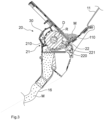
- a dosing device 20 according to the invention is shown in a side sectional view in the Fig.3 can be seen.
- the granular material M is provided to the at least one dosing element 22 on a side of the dosing device 20 facing the storage container 11, via an adjustable outlet opening 110.
- the at least one dosing element 22 is designed in the manner of a dosing wheel with at least one row of cams 220.
- the at least one dosing element 22 can also be designed in the manner of a dosing roller and/or drum with at least one, preferably several, adjacent and/or alternating rows of cams 220.
- the dosing element 22 is set up by means of the at least one row of cams 220 to convey the material M that can be fed from the storage container 11 at least partially in a direction of rotation R and to dispense it in adjustable quantities and in the direction of the dispensing elements 13, in particular via a downstream conveyor line 16.
- At least one cleaning device 30 is assigned to the at least one dosing element 22, which is designed to at least partially remove dirt and/or agglomerations of the granular material M adhering to the dosing element 22, in particular the row of cams 220, and thus to at least partially clean the dosing element 22, in particular the row of cams 220.
- the Fig.4 shows a cleaning device 30 according to the invention in a perspective view from behind.
- the cleaning device 30 is assigned to a first dosing element 22A, in particular with a small pitch of the at least one row of cams 220, and a second dosing element 22B, in particular with a large pitch of the at least one row of cams 220.
- the first and second dosing elements 22A, 22B each have a plurality of rows of cams 220 arranged offset next to one another, the first dosing element 22A being designed in the manner of a fine dosing wheel, in particular for microgranulate, and the second dosing element 22B being designed in the manner of a coarse dosing wheel, in particular for larger material M.
- the cleaning device 30 comprises at least one, in particular elastic and/or pin-like, cleaning element 31, which engages in at least one respective associated row of cams 220 and is thus designed to at least partially strip and/or clean the dosing element 22, in particular the row of cams 220.
- the at least one cleaning element 31 is arranged on at least one holding element 32.
- the cleaning device 30 is shown in a further view, in particular in individual view, in the Fig.5 can be seen particularly well.
- the cleaning device 30 comprises several cleaning elements 31 which are spaced apart from one another and which are arranged together on the holding element 32, in particular each formed like a bolt.
- the cleaning elements 31 are furthermore aligned at least substantially perpendicularly to the holding element 32, whereby alternatively a slight inclination of up to 45 degrees compared to a vertical alignment is also conceivable.
- the cleaning elements 31, in particular those adjacent to one another are at least partially offset from one another.
- the cross section of the Cleaning elements 31 are round and/or oval at least in sections.
- the cleaning device 30 is also designed in one piece, with the cleaning elements 31 and the holding element 32 being made at least almost from the same, in particular elastomeric and/or thermoplastic (TPU), plastic material.
- the holding element 32 has an at least substantially flat and/or disc-shaped form and extends with a relatively small thickness or length in the direction of the dosing element 22.
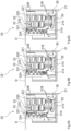
- FIG.6A to 6C An arrangement and mode of operation of the cleaning device 30, in particular of the cleaning elements 31, according to the invention is shown in the Fig.6A to 6C to be seen.
- the first cleaning element 31A is to be viewed, in particular in the position on the left outside.
- the cleaning element 31A is arranged, in particular centrally, between two adjacent rows of cams 220 of the first dosing element 22A.
- the cleaning element 31A is designed, in particular as a result of a rotary movement of the dosing element 22A, to carry out an alternating movement at least on the front side between the two rows of cams 220 of the first dosing element 22A.
- the cleaning element 31A moves, in particular in the axial direction of the dosing element 22, back and forth along several cam projections 221 arranged on the respective rows of cams 220.
- the cleaning element 31 engages at least at the front side in a left cam row 220 of the first dosing element 22A.
- the cleaning element 31A is displaced by the associated cam projection 221 towards the center and/or in the direction of the adjacent cam row 220, as in Fig.6B
- the cleaning element 31 is at least almost completely displaced into the adjacent or right cam row 220, as shown in Fig.6C can be seen.
- the two cleaning elements 31B are arranged in the direction of rotation R or circumferential direction of the dosing element 22 at an angle and/or offset in height to the cleaning element 31A of the first dosing element 22A.
- the two cleaning elements 31B are each arranged centrally to the respective associated cam row 220 of the second dosing element 22B.
- the two, in particular second, cleaning elements 31B are moved and/or deformed at least almost exclusively in a vertical direction to the axis of rotation D during the rotation of the at least one dosing element 22.
- the cleaning device 31 is, as in the Fig.7A and 7B shown in more detail, arranged and/or attachable to the cover 210 of the dosing device 20.
- the cover 210 is designed to be pivotable.
- the Fig.7A shows the cover 210 in the open position and the cleaning device 30 in a non-operating position.
- the Fig.7B shows the cover 210 in the closed position and the cleaning device 30 thus in an engaging operating position.
- the cleaning device 30 can be connected to and/or detached from at least one holding means arranged on the cover 210, but not shown in the figures.
- the cleaning device 30, in particular the holding element 32 is pushed into the at least one holding means for assembly.
- the cleaning device 30, in particular the holding element 32 After pushing in, the cleaning device 30, in particular the holding element 32, is held and/or moved to the cover 210 essentially by means of force and/or frictional engagement.
- the cleaning device 30, in particular the holding element 32 In the closed position, the cleaning device 30, in particular the holding element 32, is laterally, at least almost completely enclosed, whereby the cleaning device 30, in particular the holding element 32, is positively and/or non-positively connected to the cover, in particular the dosing device 20 and/or the housing 21.
Landscapes
- Life Sciences & Earth Sciences (AREA)
- Soil Sciences (AREA)
- Environmental Sciences (AREA)
- Cleaning In General (AREA)
- Fertilizing (AREA)
- Sowing (AREA)
Applications Claiming Priority (1)
| Application Number | Priority Date | Filing Date | Title |
|---|---|---|---|
| DE102021103452.3A DE102021103452A1 (de) | 2021-02-15 | 2021-02-15 | Dosiervorrichtung einer landwirtschaftlichen Verteilmaschine |
Publications (2)
| Publication Number | Publication Date |
|---|---|
| EP4042853A1 EP4042853A1 (de) | 2022-08-17 |
| EP4042853B1 true EP4042853B1 (de) | 2024-11-13 |
Family
ID=80684880
Family Applications (1)
| Application Number | Title | Priority Date | Filing Date |
|---|---|---|---|
| EP22401001.7A Active EP4042853B1 (de) | 2021-02-15 | 2022-02-07 | Dosiervorrichtung einer landwirtschaftlichen verteilmaschine |
Country Status (4)
| Country | Link |
|---|---|
| EP (1) | EP4042853B1 (pl) |
| DE (1) | DE102021103452A1 (pl) |
| DK (1) | DK4042853T3 (pl) |
| PL (1) | PL4042853T3 (pl) |
Families Citing this family (1)
| Publication number | Priority date | Publication date | Assignee | Title |
|---|---|---|---|---|
| CN116534256B (zh) * | 2023-07-04 | 2023-09-22 | 安徽农业大学 | 一种播撒装置及农业播种无人机 |
Family Cites Families (6)
| Publication number | Priority date | Publication date | Assignee | Title |
|---|---|---|---|---|
| DE3016832C2 (de) | 1980-05-02 | 1986-02-06 | Amazonen-Werke H. Dreyer Gmbh & Co Kg, 4507 Hasbergen | Dosiervorrichtung für körniges und pulveriges Gut |
| DE3129235C2 (de) | 1981-07-24 | 1983-05-19 | Amazonen-Werke H. Dreyer Gmbh & Co Kg, 4507 Hasbergen | Maschine zum Ausbringen von körnigem und pulverigem Material |
| US6581535B2 (en) | 2000-12-07 | 2003-06-24 | Kinze Manufacturing, Inc. | Agricultural seed meter |
| JP5237855B2 (ja) * | 2009-02-25 | 2013-07-17 | 株式会社クボタ | 農用供給装置 |
| DE102013005733A1 (de) | 2013-04-05 | 2014-10-09 | Rauch Landmaschinenfabrik Gmbh | Dosiereinheit für eine Verteilmaschine und mit einer solchen Dosiereinheit ausgestattete, insbesondere pneumatische, Verteilmaschine |
| FR3050607B1 (fr) * | 2016-04-28 | 2018-11-30 | Sulky Burel | Semoir equipe d'un dispositif de regulation de la distribution de graines, et dispositif de regulation correspondant |
-
2021
- 2021-02-15 DE DE102021103452.3A patent/DE102021103452A1/de active Pending
-
2022
- 2022-02-07 DK DK22401001.7T patent/DK4042853T3/da active
- 2022-02-07 EP EP22401001.7A patent/EP4042853B1/de active Active
- 2022-02-07 PL PL22401001.7T patent/PL4042853T3/pl unknown
Also Published As
| Publication number | Publication date |
|---|---|
| DE102021103452A1 (de) | 2022-08-18 |
| EP4042853A1 (de) | 2022-08-17 |
| PL4042853T3 (pl) | 2025-02-10 |
| DK4042853T3 (da) | 2024-12-16 |
Similar Documents
| Publication | Publication Date | Title |
|---|---|---|
| EP3357319B1 (de) | Dosiervorrichtung | |
| DE102013100118B3 (de) | Abstreifeinrichtung, Säherz und Einzelkornsämaschine | |
| EP0358878B1 (de) | Dosiervorrichtung für eine Verteilmaschine | |
| EP0056988B1 (de) | Vorrichtung zum Säubern der Scheibeninnenflächen eines aus zwei rotierenden Scheiben bestehenden Werkzeuges, insb. für Sämaschinen | |
| DE1949926C3 (de) | Drillmaschine oder Düngerstreuer mit Dosiervorrichtungen | |
| EP4042853B1 (de) | Dosiervorrichtung einer landwirtschaftlichen verteilmaschine | |
| DE3218196C1 (de) | Dosiergeraet fuer Verteilersysteme fuer koernige Stoffe,wie Saatgut oder Duenger | |
| DE3129235C2 (de) | Maschine zum Ausbringen von körnigem und pulverigem Material | |
| DE102020002762A1 (de) | Dosiervorrichtung für eine landwirtschaftliche Maschine | |
| EP3269221B1 (de) | Landwirtschaftliche sämaschine mit streichelement | |
| EP1561371B1 (de) | Kombination aus einer Schutzeinrichtung und einem Rahmenteil | |
| EP3927138B1 (de) | Dosiereinrichtung für körniges gut und verteilmaschine mit dosiereinrichtung | |
| DE102013100113B4 (de) | Abstreifer, Abstreifeinrichtung, Säherz | |
| EP4319540A1 (de) | Landwirtschaftliche verteilmaschine zum ausbringen von granularem material | |
| DE29521716U1 (de) | Dosiervorrichtung für eine Verteilmaschine | |
| DE60306362T2 (de) | Düsen für eine reinigungsanlage einer druckmaschine | |
| EP4302585A1 (de) | Dosiereinheit für pulver- oder partikelförmiges verteilgut und verteilmaschine mit einer solchen dosiereinheit | |
| EP3811752A1 (de) | Verteilmaschine | |
| EP1820382B1 (de) | Pneumatische Einzelkornsämaschine | |
| EP4008169B1 (de) | Landwirtschaftliche vereinzelungsvorrichtung zur vereinzelung von körnigem material | |
| EP1752029B1 (de) | Pneumatische Einzelkornsämaschine | |
| EP3777503B1 (de) | Landwirtschaftliche pneumatische verteilmaschine | |
| CH719148A2 (de) | Auflösewalze zur Speisung von Fasergut und Speisevorrichtung. | |
| EP0210515B1 (de) | Verteilmaschine, insbesondere Sämaschine | |
| DE293409C (pl) |
Legal Events
| Date | Code | Title | Description |
|---|---|---|---|
| PUAI | Public reference made under article 153(3) epc to a published international application that has entered the european phase |
Free format text: ORIGINAL CODE: 0009012 |
|
| STAA | Information on the status of an ep patent application or granted ep patent |
Free format text: STATUS: THE APPLICATION HAS BEEN PUBLISHED |
|
| AK | Designated contracting states |
Kind code of ref document: A1 Designated state(s): AL AT BE BG CH CY CZ DE DK EE ES FI FR GB GR HR HU IE IS IT LI LT LU LV MC MK MT NL NO PL PT RO RS SE SI SK SM TR |
|
| STAA | Information on the status of an ep patent application or granted ep patent |
Free format text: STATUS: REQUEST FOR EXAMINATION WAS MADE |
|
| 17P | Request for examination filed |
Effective date: 20230119 |
|
| RBV | Designated contracting states (corrected) |
Designated state(s): AL AT BE BG CH CY CZ DE DK EE ES FI FR GB GR HR HU IE IS IT LI LT LU LV MC MK MT NL NO PL PT RO RS SE SI SK SM TR |
|
| P01 | Opt-out of the competence of the unified patent court (upc) registered |
Effective date: 20230523 |
|
| GRAP | Despatch of communication of intention to grant a patent |
Free format text: ORIGINAL CODE: EPIDOSNIGR1 |
|
| STAA | Information on the status of an ep patent application or granted ep patent |
Free format text: STATUS: GRANT OF PATENT IS INTENDED |
|
| INTG | Intention to grant announced |
Effective date: 20240718 |
|
| RIC1 | Information provided on ipc code assigned before grant |
Ipc: A01C 7/12 20060101AFI20240712BHEP |
|
| GRAS | Grant fee paid |
Free format text: ORIGINAL CODE: EPIDOSNIGR3 |
|
| GRAA | (expected) grant |
Free format text: ORIGINAL CODE: 0009210 |
|
| STAA | Information on the status of an ep patent application or granted ep patent |
Free format text: STATUS: THE PATENT HAS BEEN GRANTED |
|
| AK | Designated contracting states |
Kind code of ref document: B1 Designated state(s): AL AT BE BG CH CY CZ DE DK EE ES FI FR GB GR HR HU IE IS IT LI LT LU LV MC MK MT NL NO PL PT RO RS SE SI SK SM TR |
|
| REG | Reference to a national code |
Ref country code: GB Ref legal event code: FG4D Free format text: NOT ENGLISH |
|
| REG | Reference to a national code |
Ref country code: CH Ref legal event code: EP |
|
| REG | Reference to a national code |
Ref country code: DE Ref legal event code: R096 Ref document number: 502022002128 Country of ref document: DE |
|
| REG | Reference to a national code |
Ref country code: IE Ref legal event code: FG4D Free format text: LANGUAGE OF EP DOCUMENT: GERMAN |
|
| REG | Reference to a national code |
Ref country code: DK Ref legal event code: T3 Effective date: 20241211 |
|
| REG | Reference to a national code |
Ref country code: SE Ref legal event code: TRGR |
|
| REG | Reference to a national code |
Ref country code: LT Ref legal event code: MG9D |
|
| REG | Reference to a national code |
Ref country code: NL Ref legal event code: MP Effective date: 20241113 |
|
| PG25 | Lapsed in a contracting state [announced via postgrant information from national office to epo] |
Ref country code: PT Free format text: LAPSE BECAUSE OF FAILURE TO SUBMIT A TRANSLATION OF THE DESCRIPTION OR TO PAY THE FEE WITHIN THE PRESCRIBED TIME-LIMIT Effective date: 20250313 Ref country code: HR Free format text: LAPSE BECAUSE OF FAILURE TO SUBMIT A TRANSLATION OF THE DESCRIPTION OR TO PAY THE FEE WITHIN THE PRESCRIBED TIME-LIMIT Effective date: 20241113 Ref country code: IS Free format text: LAPSE BECAUSE OF FAILURE TO SUBMIT A TRANSLATION OF THE DESCRIPTION OR TO PAY THE FEE WITHIN THE PRESCRIBED TIME-LIMIT Effective date: 20250313 |
|
| PGFP | Annual fee paid to national office [announced via postgrant information from national office to epo] |
Ref country code: DE Payment date: 20241210 Year of fee payment: 4 |
|
| PG25 | Lapsed in a contracting state [announced via postgrant information from national office to epo] |
Ref country code: NL Free format text: LAPSE BECAUSE OF FAILURE TO SUBMIT A TRANSLATION OF THE DESCRIPTION OR TO PAY THE FEE WITHIN THE PRESCRIBED TIME-LIMIT Effective date: 20241113 Ref country code: FI Free format text: LAPSE BECAUSE OF FAILURE TO SUBMIT A TRANSLATION OF THE DESCRIPTION OR TO PAY THE FEE WITHIN THE PRESCRIBED TIME-LIMIT Effective date: 20241113 |
|
| PGFP | Annual fee paid to national office [announced via postgrant information from national office to epo] |
Ref country code: DK Payment date: 20250214 Year of fee payment: 4 |
|
| PG25 | Lapsed in a contracting state [announced via postgrant information from national office to epo] |
Ref country code: BG Free format text: LAPSE BECAUSE OF FAILURE TO SUBMIT A TRANSLATION OF THE DESCRIPTION OR TO PAY THE FEE WITHIN THE PRESCRIBED TIME-LIMIT Effective date: 20241113 |
|
| PG25 | Lapsed in a contracting state [announced via postgrant information from national office to epo] |
Ref country code: ES Free format text: LAPSE BECAUSE OF FAILURE TO SUBMIT A TRANSLATION OF THE DESCRIPTION OR TO PAY THE FEE WITHIN THE PRESCRIBED TIME-LIMIT Effective date: 20241113 |
|
| PG25 | Lapsed in a contracting state [announced via postgrant information from national office to epo] |
Ref country code: NO Free format text: LAPSE BECAUSE OF FAILURE TO SUBMIT A TRANSLATION OF THE DESCRIPTION OR TO PAY THE FEE WITHIN THE PRESCRIBED TIME-LIMIT Effective date: 20250213 |
|
| PG25 | Lapsed in a contracting state [announced via postgrant information from national office to epo] |
Ref country code: LV Free format text: LAPSE BECAUSE OF FAILURE TO SUBMIT A TRANSLATION OF THE DESCRIPTION OR TO PAY THE FEE WITHIN THE PRESCRIBED TIME-LIMIT Effective date: 20241113 Ref country code: GR Free format text: LAPSE BECAUSE OF FAILURE TO SUBMIT A TRANSLATION OF THE DESCRIPTION OR TO PAY THE FEE WITHIN THE PRESCRIBED TIME-LIMIT Effective date: 20250214 |
|
| PGFP | Annual fee paid to national office [announced via postgrant information from national office to epo] |
Ref country code: AT Payment date: 20250417 Year of fee payment: 4 |
|
| PGFP | Annual fee paid to national office [announced via postgrant information from national office to epo] |
Ref country code: IT Payment date: 20250228 Year of fee payment: 4 |
|
| PG25 | Lapsed in a contracting state [announced via postgrant information from national office to epo] |
Ref country code: RS Free format text: LAPSE BECAUSE OF FAILURE TO SUBMIT A TRANSLATION OF THE DESCRIPTION OR TO PAY THE FEE WITHIN THE PRESCRIBED TIME-LIMIT Effective date: 20250213 |
|
| PG25 | Lapsed in a contracting state [announced via postgrant information from national office to epo] |
Ref country code: SM Free format text: LAPSE BECAUSE OF FAILURE TO SUBMIT A TRANSLATION OF THE DESCRIPTION OR TO PAY THE FEE WITHIN THE PRESCRIBED TIME-LIMIT Effective date: 20241113 |
|
| PG25 | Lapsed in a contracting state [announced via postgrant information from national office to epo] |
Ref country code: EE Free format text: LAPSE BECAUSE OF FAILURE TO SUBMIT A TRANSLATION OF THE DESCRIPTION OR TO PAY THE FEE WITHIN THE PRESCRIBED TIME-LIMIT Effective date: 20241113 |
|
| PG25 | Lapsed in a contracting state [announced via postgrant information from national office to epo] |
Ref country code: RO Free format text: LAPSE BECAUSE OF FAILURE TO SUBMIT A TRANSLATION OF THE DESCRIPTION OR TO PAY THE FEE WITHIN THE PRESCRIBED TIME-LIMIT Effective date: 20241113 |
|
| PG25 | Lapsed in a contracting state [announced via postgrant information from national office to epo] |
Ref country code: SK Free format text: LAPSE BECAUSE OF FAILURE TO SUBMIT A TRANSLATION OF THE DESCRIPTION OR TO PAY THE FEE WITHIN THE PRESCRIBED TIME-LIMIT Effective date: 20241113 |
|
| PG25 | Lapsed in a contracting state [announced via postgrant information from national office to epo] |
Ref country code: CZ Free format text: LAPSE BECAUSE OF FAILURE TO SUBMIT A TRANSLATION OF THE DESCRIPTION OR TO PAY THE FEE WITHIN THE PRESCRIBED TIME-LIMIT Effective date: 20241113 |
|
| REG | Reference to a national code |
Ref country code: DE Ref legal event code: R097 Ref document number: 502022002128 Country of ref document: DE |
|
| PG25 | Lapsed in a contracting state [announced via postgrant information from national office to epo] |
Ref country code: MC Free format text: LAPSE BECAUSE OF FAILURE TO SUBMIT A TRANSLATION OF THE DESCRIPTION OR TO PAY THE FEE WITHIN THE PRESCRIBED TIME-LIMIT Effective date: 20241113 |
|
| PLBE | No opposition filed within time limit |
Free format text: ORIGINAL CODE: 0009261 |
|
| STAA | Information on the status of an ep patent application or granted ep patent |
Free format text: STATUS: NO OPPOSITION FILED WITHIN TIME LIMIT |
|
| REG | Reference to a national code |
Ref country code: CH Ref legal event code: PL |
|
| PG25 | Lapsed in a contracting state [announced via postgrant information from national office to epo] |
Ref country code: LU Free format text: LAPSE BECAUSE OF NON-PAYMENT OF DUE FEES Effective date: 20250207 |
|
| PG25 | Lapsed in a contracting state [announced via postgrant information from national office to epo] |
Ref country code: CH Free format text: LAPSE BECAUSE OF NON-PAYMENT OF DUE FEES Effective date: 20250228 |
|
| 26N | No opposition filed |
Effective date: 20250814 |
|
| REG | Reference to a national code |
Ref country code: BE Ref legal event code: MM Effective date: 20250228 |
|
| PGFP | Annual fee paid to national office [announced via postgrant information from national office to epo] |
Ref country code: FR Payment date: 20251208 Year of fee payment: 5 |
|
| PG25 | Lapsed in a contracting state [announced via postgrant information from national office to epo] |
Ref country code: BE Free format text: LAPSE BECAUSE OF NON-PAYMENT OF DUE FEES Effective date: 20250228 |
|
| PGFP | Annual fee paid to national office [announced via postgrant information from national office to epo] |
Ref country code: SE Payment date: 20251210 Year of fee payment: 5 |
|
| PG25 | Lapsed in a contracting state [announced via postgrant information from national office to epo] |
Ref country code: IE Free format text: LAPSE BECAUSE OF NON-PAYMENT OF DUE FEES Effective date: 20250207 |
|
| PGFP | Annual fee paid to national office [announced via postgrant information from national office to epo] |
Ref country code: PL Payment date: 20251212 Year of fee payment: 5 |