EP4042501B1 - Verwendung eines verbundmaterials zur aufnahme und verteilung von flüssigkeiten in aktiv und/oder passiv gekühlten stromführenden systemen - Google Patents
Verwendung eines verbundmaterials zur aufnahme und verteilung von flüssigkeiten in aktiv und/oder passiv gekühlten stromführenden systemen Download PDFInfo
- Publication number
- EP4042501B1 EP4042501B1 EP20790227.1A EP20790227A EP4042501B1 EP 4042501 B1 EP4042501 B1 EP 4042501B1 EP 20790227 A EP20790227 A EP 20790227A EP 4042501 B1 EP4042501 B1 EP 4042501B1
- Authority
- EP
- European Patent Office
- Prior art keywords
- liquid
- layer
- water
- absorbing
- composite material
- Prior art date
- Legal status (The legal status is an assumption and is not a legal conclusion. Google has not performed a legal analysis and makes no representation as to the accuracy of the status listed.)
- Active
Links
Images


Classifications
-
- H—ELECTRICITY
- H01—ELECTRIC ELEMENTS
- H01M—PROCESSES OR MEANS, e.g. BATTERIES, FOR THE DIRECT CONVERSION OF CHEMICAL ENERGY INTO ELECTRICAL ENERGY
- H01M10/00—Secondary cells; Manufacture thereof
- H01M10/60—Heating or cooling; Temperature control
- H01M10/65—Means for temperature control structurally associated with the cells
- H01M10/655—Solid structures for heat exchange or heat conduction
-
- H—ELECTRICITY
- H01—ELECTRIC ELEMENTS
- H01M—PROCESSES OR MEANS, e.g. BATTERIES, FOR THE DIRECT CONVERSION OF CHEMICAL ENERGY INTO ELECTRICAL ENERGY
- H01M4/00—Electrodes
- H01M4/02—Electrodes composed of, or comprising, active material
- H01M4/62—Selection of inactive substances as ingredients for active masses, e.g. binders, fillers
-
- B—PERFORMING OPERATIONS; TRANSPORTING
- B01—PHYSICAL OR CHEMICAL PROCESSES OR APPARATUS IN GENERAL
- B01D—SEPARATION
- B01D53/00—Separation of gases or vapours; Recovering vapours of volatile solvents from gases; Chemical or biological purification of waste gases, e.g. engine exhaust gases, smoke, fumes, flue gases, aerosols
- B01D53/26—Drying gases or vapours
- B01D53/263—Drying gases or vapours by absorption
-
- H—ELECTRICITY
- H01—ELECTRIC ELEMENTS
- H01M—PROCESSES OR MEANS, e.g. BATTERIES, FOR THE DIRECT CONVERSION OF CHEMICAL ENERGY INTO ELECTRICAL ENERGY
- H01M10/00—Secondary cells; Manufacture thereof
- H01M10/60—Heating or cooling; Temperature control
-
- H—ELECTRICITY
- H01—ELECTRIC ELEMENTS
- H01M—PROCESSES OR MEANS, e.g. BATTERIES, FOR THE DIRECT CONVERSION OF CHEMICAL ENERGY INTO ELECTRICAL ENERGY
- H01M10/00—Secondary cells; Manufacture thereof
- H01M10/60—Heating or cooling; Temperature control
- H01M10/61—Types of temperature control
- H01M10/613—Cooling or keeping cold
-
- H—ELECTRICITY
- H01—ELECTRIC ELEMENTS
- H01M—PROCESSES OR MEANS, e.g. BATTERIES, FOR THE DIRECT CONVERSION OF CHEMICAL ENERGY INTO ELECTRICAL ENERGY
- H01M10/00—Secondary cells; Manufacture thereof
- H01M10/60—Heating or cooling; Temperature control
- H01M10/65—Means for temperature control structurally associated with the cells
- H01M10/656—Means for temperature control structurally associated with the cells characterised by the type of heat-exchange fluid
- H01M10/6567—Liquids
-
- H—ELECTRICITY
- H01—ELECTRIC ELEMENTS
- H01M—PROCESSES OR MEANS, e.g. BATTERIES, FOR THE DIRECT CONVERSION OF CHEMICAL ENERGY INTO ELECTRICAL ENERGY
- H01M50/00—Constructional details or processes of manufacture of the non-active parts of electrochemical cells other than fuel cells, e.g. hybrid cells
- H01M50/20—Mountings; Secondary casings or frames; Racks, modules or packs; Suspension devices; Shock absorbers; Transport or carrying devices; Holders
- H01M50/233—Mountings; Secondary casings or frames; Racks, modules or packs; Suspension devices; Shock absorbers; Transport or carrying devices; Holders characterised by physical properties of casings or racks, e.g. dimensions
- H01M50/24—Mountings; Secondary casings or frames; Racks, modules or packs; Suspension devices; Shock absorbers; Transport or carrying devices; Holders characterised by physical properties of casings or racks, e.g. dimensions adapted for protecting batteries from their environment, e.g. from corrosion
-
- H—ELECTRICITY
- H01—ELECTRIC ELEMENTS
- H01M—PROCESSES OR MEANS, e.g. BATTERIES, FOR THE DIRECT CONVERSION OF CHEMICAL ENERGY INTO ELECTRICAL ENERGY
- H01M50/00—Constructional details or processes of manufacture of the non-active parts of electrochemical cells other than fuel cells, e.g. hybrid cells
- H01M50/50—Current conducting connections for cells or batteries
- H01M50/572—Means for preventing undesired use or discharge
-
- B—PERFORMING OPERATIONS; TRANSPORTING
- B01—PHYSICAL OR CHEMICAL PROCESSES OR APPARATUS IN GENERAL
- B01D—SEPARATION
- B01D2257/00—Components to be removed
- B01D2257/80—Water
-
- Y—GENERAL TAGGING OF NEW TECHNOLOGICAL DEVELOPMENTS; GENERAL TAGGING OF CROSS-SECTIONAL TECHNOLOGIES SPANNING OVER SEVERAL SECTIONS OF THE IPC; TECHNICAL SUBJECTS COVERED BY FORMER USPC CROSS-REFERENCE ART COLLECTIONS [XRACs] AND DIGESTS
- Y02—TECHNOLOGIES OR APPLICATIONS FOR MITIGATION OR ADAPTATION AGAINST CLIMATE CHANGE
- Y02E—REDUCTION OF GREENHOUSE GAS [GHG] EMISSIONS, RELATED TO ENERGY GENERATION, TRANSMISSION OR DISTRIBUTION
- Y02E60/00—Enabling technologies; Technologies with a potential or indirect contribution to GHG emissions mitigation
- Y02E60/10—Energy storage using batteries
Definitions
- the invention relates to the use of a composite material for receiving and distributing liquids in actively and/or passively cooled power-carrying systems, in particular in actively and/or passively cooled power storage systems.
- the invention further relates to an absorber pad and an actively and/or passively cooled current-carrying system, which contain the composite material.
- a "current-carrying system” is a system through which electric current flows.
- Practically relevant current-carrying systems are “electricity storage systems”, i.e. systems for storing currently available but not needed energy for later use. This storage is often accompanied by a conversion of the form of energy, for example from electrical to chemical energy. If necessary, the energy is then converted back into the desired electrical form.
- Battery systems are known to be modules connected in series or parallel, which contain secondary or primary cells connected in series or parallel contain.
- Other power storage systems are accumulators, i.e. modules connected in series or parallel that contain secondary cells connected in series or parallel.
- Also practically relevant electricity storage systems are capacitors, i.e. passive electrical components with the ability to statically store electrical charge and the associated energy in an electrical field in a direct current circuit.
- the systems are usually not hermetically sealed from the environment. This means that they allow gas exchange with the environment. To prevent contamination from entering, the incoming air is filtered.
- microporous films or nonwovens are used.
- the condensate formed can only be removed from the housing with difficulty.
- pumps, controlled valves or baking would be conceivable here. These approaches are complex and may be prone to errors. Baking out is also prohibited in many applications (e.g. battery systems).
- Another problem is that, for example in the event of an accident in a vehicle equipped in this way, leaks can occur and the temperature control medium can therefore escape from the heat sink.
- the temperature control agent can then come into direct contact with the battery cells and, for example, trigger a short circuit due to its conductivity.
- a common desiccant is P 2 O 5 . Although this has an extremely high absorption capacity for water, it forms liquid phosphoric acid when water is absorbed. This can lead to corrosion and poses a risk for electrical applications due to its electrical conductivity. In addition, water absorption is irreversible. Other typical drying agents such as CaCl 2 react similarly.
- the desiccant is usually sealed loosely in bags (desiccant bags) and is therefore not reliably fixed.
- Superabsorbers lead to strong swelling and possibly gel formation with polar liquid media.
- swelling can lead to transport channels of the liquid being blocked by the swelling process (so-called blocking effect) and subsequent absorption is no longer possible.
- swelling in electronic devices is disadvantageous or harmful from two other points of view:
- the swollen material can build up mechanical pressures, which can, for example, separate electrical contacts.
- the swollen material swells uncontrollably, it can cause electrical short circuits if it comes into contact with live parts.
- Superabsorber materials are known, for example, from medical products and, for example, in DE102006031418A1 described.
- EP2731164 (A1) describes a battery system comprising battery cells, at least one absorption element and a temperature control system with a liquid temperature control agent for cooling and/or heating the battery cells in a battery housing.
- the absorption element for receiving the liquid temperature control agent is arranged between the battery cells and the battery housing, the absorption element being a fleece, the fleece having an average mass per unit area of 250 to 700 g/m 2 and comprising fibers of at least two different fiber types, wherein at least one of the fiber types is a supporting fiber and at least another one of the fiber types is an absorption fiber.
- absorption fibers generally have a lower absorption capacity than comparable absorbent particles.
- they generally have lower thermal stability in both the dry and swollen states.
- absorbent fibers as explained above, can result in a gel blocking effect.
- a device for setting essentially constant ambient conditions for an electrical component that is designed to carry current and/or store electricity is known.
- the electrical component is surrounded by a housing that has an opening in order to maintain a connection to the external environment of the housing.
- a moisture absorbing member may be used.
- Superabsorbers are called moisture-absorbing elements.
- the DE 10 2017 004 296 A1 describes a high-voltage component for a motor vehicle, with a housing in which at least one element provides an electrical voltage and/or operates with electrical voltage acted upon element is arranged, and with a sensor device for detecting impairment of the high-voltage component.
- the sensor device has a layer designed to absorb a liquid and an electrical conductor connected to a measuring device of the sensor device.
- the measuring device is designed to detect a change in the electrical resistance of the layer depending on the presence of liquid in the layer.
- the object of the invention is to at least partially eliminate the aforementioned disadvantages.
- a material should be provided that has good water absorption and retention.
- the material should also be able to reversibly bind water and possibly water vapor.
- it should have controlled swellability and a blocking effect should be avoided. After all, it should be usable with little dust.
- This object is achieved by the use of a composite material comprising a carrier layer and a liquid receiving layer fixed on the carrier layer, the liquid receiving layer containing fixed superabsorbent particles, a liquid distribution layer which is in liquid-conducting contact with the liquid receiving layer being arranged on the side of the liquid receiving layer facing away from the carrier layer, which receives and distributes a liquid to be absorbed in the plane of the composite material, for receiving and distributing liquids in actively and/or passively cooled power-carrying systems, in particular in actively and/or passively cooled power storage systems.
- the composite material described above is excellent for absorbing and distributing liquids in actively and/or passively cooled current-carrying systems, as the fixation of the superabsorbent particles significantly reduces the risk of dust formation.
- the superabsorbent particles are preferably fixed to the carrier layer, for example by means of a binder. This is particularly advantageous in the case of mechanical stress, such as occurs when the composite material is used in automobiles.
- the fixation makes it possible to use superabsorbents in particle form. These have the advantage over superabsorbent fibers that they have a higher absorption capacity with comparable thermal stability in both the dried and swollen states.
- the composite material shows a very low gel blocking effect, since the liquid distribution layer used absorbs and distributes the liquid to be absorbed in the plane of the composite material. This allows the absorption capacity of the liquid absorption layer to be optimally utilized.
- the composite material is suitable for a wide variety of actively and/or passively cooled current-carrying systems, for example battery systems, inverters/power electronics systems and/or Charging stations.
- a wide variety of liquids can be absorbed, for example water and/or other cooling media, such as water-glycol mixtures.
- Current-carrying systems preferred according to the invention are current-carrying systems selected from a power storage system, a current-carrying energy converter, a transformer, a power electronics system, an electronic control system, in particular a processor-controlled system, a charging station, an inverter, a rectifier, an electrolyzer and/or combinations thereof.
- preferred power storage systems are battery systems, capacitors and/or accumulators. Battery systems are particularly preferred.
- Superabsorbents are characterized by their excellent ability to bind and absorb liquid.
- a superabsorbent is understood to mean a polymer that is able to absorb or absorb a multiple of its own weight - up to 500 times - in liquids, preferably water, while increasing in volume.
- Suitable superabsorbents are, in particular, cross-linked polymers that are polar.
- Polyacrylamide, polyvinylpyrrolidone, amylopectin, gelatin and cellulose are particularly preferred.
- the ratio of the two monomers to one another can vary.
- a so-called core cross-linker (CXL) is usually added to the above-mentioned monomers, which connects (crosslinks) the long-chain polymer molecules formed in places using chemical bridges. These bridges make the polymer insoluble in water.
- CXL core cross-linker
- SXL surface cross-linker
- Another chemical is applied to the surface of the particles, which, when heated, forms a second network only on the outer layer of the grain. This cover supports the swollen gel in order to keep it together even under external stress (movement, pressure).
- the superabsorbent particles are on the carrier layer with a binder, in particular with a water-soluble binder, such as polyvinyl alcohol, starch, polyvinylpyrolidone, casein glue, polyvinyl butyral and / or with a water-swellable binder, such as at least partially crosslinked polyvinyl alcohol and/or partially cross-linked starch.
- a water-soluble binder such as polyvinyl alcohol, starch, polyvinylpyrolidone, casein glue, polyvinyl butyral and / or with a water-swellable binder, such as at least partially crosslinked polyvinyl alcohol and/or partially cross-linked starch.
- a water-soluble binder are binders with a water solubility of at least 1 g/l, for example 1 g/l to 400 g/l, more preferably from 2 g/l to 350 g/l and in particular from 5 g/l to 300 g/l , measured at 23°C
- the proportion of the water-soluble binder and/or water-swellable binder, based on the total amount of binder is at least 70% by weight. for example 70% by weight to 100% by weight, more preferably from 80% by weight to 100% by weight and in particular from 90% by weight to 100% by weight.
- the superabsorbent particles have a swelling retardant.
- the advantage of this is that the swelling of the superabsorbent particles can be delayed, whereby the distribution of the liquid to be absorbed can be optimized and the receiving surface of the liquid receiving layer can be utilized particularly well.
- the swelling retardant can consist of the same materials as the water-soluble and/or swellable binder.
- the superabsorbent particles are at least partially, preferably completely, coated by the swelling retarding agent.
- the liquid distribution layer absorbs a liquid to be absorbed and distributes it in the plane of the composite material.
- the liquid distribution layer comprises a nonwoven fabric, a woven fabric, a knitted fabric, an open-pore foam and/or a binder, preferably a water-soluble and/or water-swellable binder.
- Preferred water-soluble binders are polyvinyl alcohol, starch, polyvinylpyrolidone, casein glue, polyvinyl butyral.
- Preferred water-swellable binders are, for example, at least partially cross-linked polyvinyl alcohol and/or partially cross-linked starch. The advantage of these materials is their good water permeability coupled with high structural integrity even when wet.
- Preferred nonwovens are spunbonded nonwovens, wet-laid nonwovens and/or dry-laid nonwovens.
- the basis weight is preferably 10 g/m 2 to 500 g/m 2 .
- the surface energy of the liquid distribution layer is greater than 30 mN/m, preferably greater than 35 mN/m and particularly preferably greater than 40 mN/m.
- polar media such as water or water/glycol mixtures can be distributed particularly well.
- the liquid distribution layer comprises at least two distribution layers, with at least one distribution layer being water-soluble and at least one other distribution layer being not water-soluble.
- the water-soluble distribution layer may consist of the same materials as the water-soluble and/or swellable binder used for the superabsorbent particles.
- the water-insoluble distribution layer preferably contains thermoplastic polymers, especially with a melting point of below 260 ° C. Particularly preferred polymers are polyesters, copolyesters, polyamides, copolyamides, polyolefins and/or blends thereof. The advantage of this is that they can be used for thermal welding.
- the air permeability of the liquid distribution layer is more than 10 dm 3 /(m 2 s), preferably in the range from 20 to 3000 dm 3 /(m 2 s), even more preferably from 30 to 2000 dm 3 /(m 2 s), particularly preferably in the range from 30 to 1000 dm 3 /(m 2 s).
- the air permeability is measured according to DIN EN ISO 9237 at a differential pressure of 100 Pa. The measurements of the air permeability are carried out before contact with liquid with samples with a thickness of 0.05 to 10 mm, preferably 3 mm, an air-flowed sample area of 20 cm 2 , with an air pressure difference of 100 Pa.
- the distribution layer in particular the water-insoluble water distribution layer, has an average pore size of more than 1 ⁇ m, for example from 1 ⁇ m to 1000 ⁇ m, preferably from 10 to 800 ⁇ m.
- the distribution layer has microfibers, preferably with a titer of less than 1 dtex, for example from 0.01 to 1 dtex, more preferably from 0.01 to 0.9 dtex.
- a titer of less than 1 dtex for example from 0.01 to 1 dtex, more preferably from 0.01 to 0.9 dtex.
- the composite material has a liquid absorption quantity (DI water) of at least 2 l/m 2 , for example from 2 l/m 2 to 200 l/m 2 , more preferably from 3 l/m 2 to 200 l /m 2 , more preferably from 5 l/m 2 to 200 l/m 2 , even more preferably from 10 l/m 2 to 200 l/m 2 and in particular from 20 l/m 2 to 200 l/m 2 .
- DI water liquid absorption quantity
- the carrier layer preferably contains thermoplastic polymers, especially with a melting point of below 270 ° C.
- Particularly preferred polymers are polyesters, copolyesters, polyamides, copolyamides, polyolefins and/or blends thereof. The advantage of this is that they can be used for thermal welding.
- the carrier layer preferably comprises a nonwoven fabric, a woven fabric, a knitted fabric, and/or an open-pore foam.
- Preferred nonwovens are spunbonded nonwovens, wet-laid nonwovens and/or dry-laid nonwovens.
- the basis weight is preferably 10 g/m 2 to 500 g/m 2 .
- the composite material is compressible and can thereby be fixed well in actively and/or passively cooled power-carrying systems, in particular in actively and/or passively cooled power storage systems. In addition, good contact with adjacent components can be ensured.
- the composite material has a water-insoluble liquid distribution layer which contains thermoplastic polymers and a support layer which also contains thermoplastic polymers.
- a water-insoluble liquid distribution layer which contains thermoplastic polymers
- a support layer which also contains thermoplastic polymers.
- the water-insoluble liquid distribution layer and the carrier layer can be used particularly well welded together. Therefore, the carrier layer and the liquid distribution layer are preferably welded and/or weldable to one another.
- the liquid-absorbing layer can be limited in terms of its expansion in the height direction when liquid is absorbed.
- the composite material according to the invention has good sound absorption properties.
- the composite material has an absorption coefficient measured according to EN ISO 354:2003 at a frequency of 6300 Hz of more than 0.09, more preferably more than 0.2 and particularly preferably more than 0.25 and/or at a frequency of 8000 Hz of more than 0.1, more preferably more than 0.25 and particularly preferably more than 0.3. This was surprising because it was expected that the coating with the superabsorbent particles would result in a composite material with low air permeability and, as a result, a low absorption coefficient.
- the composite material can be in a water-permeable bag which is welded at the edge.
- Several composite materials can also be arranged in the bag.
- the composite material can be arranged in the bag in various ways. If the composite material is in the form of absorber pads, these can be stacked on top of each other in the bag. If the composite material is in the form of sheet goods, it can be folded like an accordion and/or rolled up and pressed flat in the bag.
- At least one composite material is present as an absorber pad.
- An absorber pad is a composite material that is cut to size and welded at the edges. This can prevent the superabsorbent particles from swelling out.
- a further subject of the present invention includes an absorber pad containing a composite material according to one or more of the described embodiments.
- Another preferred absorber pad is a composite material cut to size and connected with a seam at the edges.
- the absorber pad can have a wide variety of symmetrical and/or asymmetrical geometric shapes.
- the absorber pad can have a composite material thermally welded at the edge, comprising a non-water-soluble distribution layer and a carrier layer, the non-water-soluble distribution layer and the carrier layer being thermally melted at the edge with partial penetration of the liquid receiving layer and thereby thermally bonding the layers to one another at the edge.
- the absorber pad has two composite materials, each of which, as described above, has a carrier layer and a liquid absorption layer fixed on the carrier layer, wherein the Liquid receiving layer contains fixed superabsorbent particles, and wherein on the side of the liquid receiving layer facing away from the carrier layer there is arranged a liquid distribution layer which is in liquid-conducting contact with the liquid receiving layer and which receives and distributes a liquid to be absorbed in the plane of the composite material.
- a first distribution layer associated with a first composite material includes a water-soluble distribution layer and a water-insoluble distribution layer
- a second distribution layer associated with a second composite material includes a water-soluble distribution layer.
- the two composite materials are arranged so that the liquid absorption layers face each other.
- the absorber pad is thermally welded all around the edge, with at least one water-insoluble distribution layer being at least partially melted, thereby partially penetrating the liquid absorption layers and thereby fixing the absorber pad.
- at least one carrier layer is preferably at least partially melted and supports the fixation of the absorber pad.
- the absorber pad has two composite materials, each of which, as described above, has a carrier layer and a liquid-receiving layer fixed on the carrier layer, the liquid-receiving layer containing fixed superabsorbent particles, and one with the liquid-receiving layer on the side of the liquid-receiving layer facing away from the carrier layer
- a liquid distribution layer is arranged in liquid-conducting contact, which receives and distributes a liquid to be absorbed in the plane of the composite material.
- the two composite materials are arranged so that the liquid absorption layers face each other.
- the absorber pad is thermally welded all around the edge, with at least one carrier layer being at least partially melted, the Has partially penetrated the liquid absorption layers and thereby caused the absorber pad to be fixed.
- at least one water-insoluble distribution layer is preferably at least partially melted and supports the fixation of the absorber pad.
- the absorber pad has two composite materials, each of which, as described above, has a carrier layer and a liquid-receiving layer fixed on the carrier layer, the liquid-receiving layer containing fixed superabsorbent particles, and one with the liquid-receiving layer on the side of the liquid-receiving layer facing away from the carrier layer
- a liquid distribution layer is arranged in liquid-conducting contact, which receives and distributes a liquid to be absorbed in the plane of the composite material.
- a first distribution layer associated with a first composite material includes a water-soluble distribution layer and a water-insoluble distribution layer
- a second distribution layer associated with a second composite material includes a water-soluble distribution layer.
- thermoplastic adhesive preferably (co-)polyester, (co-)polyamide, polyurethane and/or polyolefin, in particular in the form of a two-dimensional sheet material such as fleece, film, woven and/or knitted fabric, is arranged between these liquid absorption layers.
- the absorber pad is thermally welded all around the edge, whereby the thermoplastic adhesive has been at least partially melted, partially penetrating the liquid absorption layers and thereby fixing the absorber pad.
- at least one carrier layer is also at least partially melted and supports it Fixing the absorber pad.
- the absorber pad contains a composite material comprising a non-water-soluble, meltable distribution layer and a meltable carrier layer.
- the liquid distribution layer and the carrier layer protrude beyond the liquid receiving layer and are welded together, including the liquid receiving layer.
- the absorber pad has an absorption coefficient, measured according to EN ISO 354:2003 at a frequency of 6300 Hz, of more than 0.09, more preferably of more than 0.2 and particularly preferably of more than 0.25 and /or at a frequency of 8000 Hz of more than 0.1, more preferably more than 0.25 and particularly preferably more than 0.3.
- the absorber pad preferably has at least two composite materials, since particularly good acoustic properties have been achieved with multi-layer products in practical tests.
- the absorber pad 2 to 8 preferably has 3 to 8 and in particular 3 to 7 composite materials in such an arrangement that the outer layers are formed by the carrier layers.
- the absorber pad can be at least partially thermally welded all around the edge. The welding enables at least partial melting of the carrier layer, whereby the liquid receiving layers can be partially penetrated and all layers can thereby be thermally connected to one another.
- a further embodiment comprises an absorber pad in which at least one carrier layer and at least one liquid distribution layer and/or at least 2 carrier layers are at least partially connected to one another at the edges by at least one seam.
- a further embodiment comprises an absorber pad in which at least one composite material is present in a water-permeable bag which is at least partially closed at its edges by at least one seam.
- the at least one seam can be designed as a fin seam or as an overlap seam. If the bag is closed by several seams, these can be designed independently of one another as a fin seam or as an overlap seam.
- the shape of the bag may vary. Common packaging designs have proven to be suitable.
- the bag can be obtained by connecting two layers of bags all around using seams. This usually results in 1 to 4, preferably 4, seams.
- the bag can be obtained by folding a layer of bags into a tube and connecting them with seams at the open edges. This usually results in 3 seams.
- the at least one seam is designed as a weld seam, in particular as a thermally and/or ultrasonically welded seam, adhesive seam and/or needled seam.
- welded seams are that they can be created particularly quickly and easily.
- the at least one seam can be continuous and/or discontinuous.
- Discontinuous seams are made up of direct seam surfaces, ie those areas of the seam that serve to bind the two layers and/or close the bag, and indirect seam surfaces, ie those areas of the seam that lie between the immediate seam surfaces.
- the immediate seam surfaces are the welded areas; in the case of sewn seams, the areas covered by the thread Areas, in the case of taped seams, the areas connected by adhesive.
- Discontinuous seams have the advantage that they have a smaller proportion of seam area and therefore offer greater strength in relation to the area.
- the at least one seam can also be designed as a straight or curved line or combinations thereof.
- the at least one seam can be designed in the form of linear and/or regularly arranged points and/or lines. As explained above, those portions of the seam that serve to bind the layers and/or close the water-permeable bag are the immediate seam surfaces of the seam.
- the width of the at least one seam is preferably 0.5 to 15 mm, more preferably 0.5 to 10 mm and particularly preferably 1 to 6 mm. More preferably, the seam area, i.e.
- the sum of indirect and direct seam areas on the surface of the absorber material is at least 0.4 to 50 area%, more preferably 2 to 40 area% and particularly preferably 4 to 35 area%. If the seam area is less than 0.4 area%, the strength of the seam is usually too low.
- the at least one seam is designed as a weld seam, which is perforated, preferably in its middle.
- the absorber material can be adapted to the installation situation in a particularly simple manner.
- recesses can be specifically formed by removing partial areas along the perforated weld seam.
- the shape of the weld can vary.
- the transition between the weld seam and the non-welded areas of the layers is smooth. Therefore takes in a preferred Embodiment the thickness of the welded areas of the weld seam towards the edge. Accordingly, the density of the welded areas of the weld seam increases towards the edge.
- the transition between the weld seam and the pocket is preferably continuous. The advantage of this is a higher strength of the weld seam.
- a further subject of the invention is an actively and/or passively cooled current-carrying system, comprising a composite material, preferably designed as an absorber pad, comprising a carrier layer and a liquid receiving layer fixed on the carrier layer and containing superabsorbent particles, the liquid receiving layer being on the side facing away from the carrier layer a liquid distribution layer is arranged which is in liquid-conducting contact with the liquid receiving layer and which receives and distributes a liquid to be absorbed in the plane of the composite material.
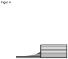
- FIG 4 the cross section of a seam is shown.
- the seam is in the form of a weld seam.
- the thickness of the weld decreases towards the edge. Accordingly, the density of the weld seam increases towards the edge. This transition is continuous.
- Example 1 Production of composite materials that can be used according to the invention
- Microfiber spunbond Polyamide / polyester microfiber spunbond "Evolon ® "; 200 g/ m2 .
- Superabsorbent particles 1 Partially neutralized and cross-linked polyacrylic acid, produced using the bulk polymerization process with a particle size distribution d 50 of 50 ⁇ m - 1000 ⁇ m, application weight 15 g/m2.
- Superabsorbent particles 2 Partially neutralized and cross-linked polyacrylic acid, produced using the inverse suspension polymerization process with a particle size distribution d 50 of 50 ⁇ m - 1000 ⁇ m, application weight 15 g/m 2 .
- Water soluble distribution layer 1 Water-soluble, partially saponified polyvinyl alcohol with an application weight of 20 g/m 2
- Water soluble distribution layer 2 Water-soluble starch with an application weight of 20 g/m 2
- the table below shows the layer structure used Composite material Liquid distribution position Fluid intake position Carrier layer 1 - Water-soluble distribution layer 1 1 in combination with Superabsorbent particles 1 fixed to the carrier layer with PVA Microfiber spunbond - non-water-soluble distribution layer microfiber spunbond 2 - water-soluble distribution layer 1 in combination with Superabsorbent particles 2 fixed to the carrier layer with PVA
- Thematically bound PES - non-water-soluble distribution layer thermoally bonded PES staple fiber nonwoven, 40 g/m 2 Staple fiber nonwoven, 40 g/ m2 3 - water-soluble distribution layer 2 in combination with Superabsorbent particles 1 fixed to the carrier layer with PVA
- Binder bound PES - non-water-soluble distribution layer biner-bound PES staple fiber nonwoven, 40 g/m 2
- Staple fiber nonwoven 40 g/ m2 4 - water-soluble distribution layer 1 in combination with Superabsorbent particles 2 fixed to the carrier layer with PVA thermally bonded PP spunbond, 60
- the layers are connected as follows: First, the carrier layer is presented and coated with the water-soluble distribution layer and the superabsorbent particles. The water-insoluble distribution layer, if used, is then added.
- the composite materials 1 to 5 are each arranged between 2 thermally weldable layers (bag layers, microfiber spunbond 80 g/m 2 ), the edges of which extend beyond the composite materials, and the edges of these layers are welded to form an absorber pad.
- the cutting step can take place before or after welding.
- the composite materials 1 - 5 are thermally welded all around the edge, with the non-water-soluble distribution layer and the carrier layer melting and thereby partially penetrating the liquid absorption layer and thereby thermally connecting all layers to one another.
- 2 composite materials 5 are arranged so that the liquid receiving layers face each other.
- the composite obtained in this way is thermally welded all around the edge, whereby the carrier layer melts, partially penetrating the liquid-absorbing layers and thereby thermally connecting all layers to one another.
- the cutting step can take place before or after welding. This results in absorber pad 6a.
- 4 composite materials 5 are arranged so that the carrier layers form the outer layers.
- the composite obtained in this way is thermally welded all around the edge, whereby the carrier layers melt, partially penetrating the liquid absorption layers and thereby thermally connecting all layers to one another.
- the cutting step can take place before or after welding. This results in absorber pad 6b.
- 6 composite materials 5 are arranged so that the carrier layers form the outer layers.
- the composite obtained in this way is thermally welded all around the edge, whereby the carrier layers melt, partially penetrating the liquid absorption layers and thereby thermally connecting all layers to one another.
- the cutting step can take place before or after welding. This results in absorber pad 6c.
- 2 composite materials 5 are arranged so that the liquid receiving layers face each other.
- An adhesive fleece (copolyester fleece, 30 g/m 2 , mp. 100-110°C) is arranged between these liquid absorption layers.
- the composite obtained in this way is thermally welded all around the edge, whereby the adhesive fleece melts and partially penetrates the liquid absorption layers and thereby thermally connects all layers to one another. This results in absorber pad 7.
- Example 2 Testing the absorption capacity of an absorber pad according to the invention.
- the absorption capacity of the absorber pad 7 was tested according to DIN 53923 with fully demineralized water. It was found that the absorber pad 7 has a good water absorption of 8.7 kg/m 2 . As part of the test according to DIN 53923, the absorber pad 7 is suspended freely in a swollen state for 30 seconds. Here the water loss is 550 g/m 2 and therefore corresponds to very good retention. The absorber pad could also be easily dried without heating, which shows that it is also able to reversibly bind water. Thanks to the all-round welding, the swelling could be well controlled and a blocking effect could be avoided by using distributor layers. By fixing the superabsorbent particles, dust formation could be avoided.
- Example 3 Testing the water vapor absorption of an absorber pad according to the invention
- the water vapor absorption of the absorber pad 7 was tested.
- the absorber pad was stored in a climate cabinet for a period of 270 minutes at 90% humidity and 30°C. Weight gain was determined gravimetrically every 30 minutes over a period of 270 min.
- the absorber pad 7 was then dried at room temperature and the weight loss was determined gravimetrically. This process was repeated 5 times and is in Figure 1 shown.
- Example 4 Testing the water vapor absorption of an absorber pad not according to the invention
- the water vapor absorption of an absorber pad not according to the invention was tested.
- the absorber pad consists of a non-woven fabric bag that is filled with 1g of loose superabsorbent particles 2. Weight gain was determined gravimetrically every 30 minutes over a period of 270 min.
- the absorber pad not according to the invention was then dried at room temperature for 20 hours and the weight loss was determined gravimetrically. This process was repeated 5 times and is in Figure 2 shown. It turns out that water vapor absorption occurs much more slowly. The water vapor absorption reaches equilibrium after 90 minutes at the earliest. In addition, the re-drying was not complete even after 20 hours.
- Example 5 Testing the sound absorption properties of an absorber pad according to the invention.
Landscapes
- Chemical & Material Sciences (AREA)
- General Chemical & Material Sciences (AREA)
- Chemical Kinetics & Catalysis (AREA)
- Electrochemistry (AREA)
- Engineering & Computer Science (AREA)
- Manufacturing & Machinery (AREA)
- Oil, Petroleum & Natural Gas (AREA)
- Analytical Chemistry (AREA)
- Laminated Bodies (AREA)
- Secondary Cells (AREA)
- Battery Electrode And Active Subsutance (AREA)
- Sorption Type Refrigeration Machines (AREA)
- Compositions Of Macromolecular Compounds (AREA)
Applications Claiming Priority (2)
| Application Number | Priority Date | Filing Date | Title |
|---|---|---|---|
| DE102019127180 | 2019-10-09 | ||
| PCT/EP2020/078201 WO2021069539A1 (de) | 2019-10-09 | 2020-10-08 | Verwendung eines verbundmaterials zur aufnahme und verteilung von flüssigkeiten in aktiv und/oder passiv gekühlten stromführenden systemen |
Publications (2)
| Publication Number | Publication Date |
|---|---|
| EP4042501A1 EP4042501A1 (de) | 2022-08-17 |
| EP4042501B1 true EP4042501B1 (de) | 2023-09-13 |
Family
ID=72852625
Family Applications (1)
| Application Number | Title | Priority Date | Filing Date |
|---|---|---|---|
| EP20790227.1A Active EP4042501B1 (de) | 2019-10-09 | 2020-10-08 | Verwendung eines verbundmaterials zur aufnahme und verteilung von flüssigkeiten in aktiv und/oder passiv gekühlten stromführenden systemen |
Country Status (12)
| Country | Link |
|---|---|
| US (1) | US12334527B2 (pl) |
| EP (1) | EP4042501B1 (pl) |
| JP (1) | JP7480286B2 (pl) |
| KR (1) | KR102827776B1 (pl) |
| CN (1) | CN114502257B (pl) |
| CA (1) | CA3149616C (pl) |
| ES (1) | ES2967041T3 (pl) |
| HU (1) | HUE064352T2 (pl) |
| MX (1) | MX2022004357A (pl) |
| PL (1) | PL4042501T3 (pl) |
| TW (1) | TWI780494B (pl) |
| WO (1) | WO2021069539A1 (pl) |
Families Citing this family (1)
| Publication number | Priority date | Publication date | Assignee | Title |
|---|---|---|---|---|
| WO2024197722A1 (zh) * | 2023-03-30 | 2024-10-03 | 台湾科德宝宝翎不织布股份有限公司 | 不织布复合材料及其纺织产品 |
Family Cites Families (25)
| Publication number | Priority date | Publication date | Assignee | Title |
|---|---|---|---|---|
| GB1508974A (en) | 1974-03-20 | 1978-04-26 | Collins R | Molten metal samplers |
| GB1456353A (en) | 1974-05-06 | 1976-11-24 | Leeds & Northrup Co | Immersion sampler for molten material |
| US4453424A (en) | 1981-04-29 | 1984-06-12 | Haly, Inc. | Molten metal sampler |
| JPS5835461A (ja) | 1981-08-27 | 1983-03-02 | Dowa Mining Co Ltd | 溶融金属のサンプラ−およびその製造法 |
| US4499777A (en) | 1983-03-03 | 1985-02-19 | Haly, Inc. | Molten metal samplers |
| US4842594A (en) * | 1983-08-24 | 1989-06-27 | Chicopee | Absorbent article with internal wicking means |
| JP4073508B2 (ja) * | 1996-07-12 | 2008-04-09 | 株式会社日本触媒 | 吸水性複合体および吸水性物品 |
| JP2002224161A (ja) | 2001-01-31 | 2002-08-13 | Mitsubishi Chemicals Corp | 吸水性物品 |
| JP2003300296A (ja) * | 2002-04-10 | 2003-10-21 | Fujikoo:Kk | 結露吸収シートの製造方法 |
| ATE391518T1 (de) * | 2003-09-25 | 2008-04-15 | Procter & Gamble | Absorbierende artikel enthaltend superabsorbierende polymerpartikeln, mit einer nicht-kovalent gebundenen beschichtung |
| DE102006031418B4 (de) | 2005-07-05 | 2013-06-06 | Birgit Riesinger | Okklusiv- oder Semiokklusivverband zur Auflage an menschliche oder tierische Wundflächen und dessen Verwendung |
| US20070142803A1 (en) * | 2005-12-15 | 2007-06-21 | Soerens Dave A | Articles comprising superabsorbent polymer compositions |
| WO2008011024A2 (en) * | 2006-07-18 | 2008-01-24 | Ali Razavi | Multifunctional articles and method for making the same |
| DE102010022327A1 (de) * | 2010-06-01 | 2011-12-01 | Schaeffler Technologies Gmbh & Co. Kg | Vorrichtung zur Einstellung von Umgebungsbedingungen für ein elektrisches Bauteil |
| DE102010017561B4 (de) | 2010-06-24 | 2023-08-31 | Dr. Ing. H.C. F. Porsche Aktiengesellschaft | Kühlvorrichtung für eine Batterie |
| JP2012094376A (ja) * | 2010-10-27 | 2012-05-17 | Sanyo Electric Co Ltd | バッテリー装置の冷却構造 |
| HUE066380T2 (hu) | 2010-12-29 | 2024-08-28 | Byd Co Ltd | Akkumulátormodul, akkumulátor-hõmérséklet kezelõ rendszer és az ezt tartalmazó jármû |
| EP2799047B1 (en) * | 2011-12-27 | 2017-07-19 | Sumitomo Seika Chemicals Co. Ltd. | Water-absorbent sheet composite |
| EP2615120B2 (en) * | 2012-01-12 | 2022-12-21 | Evonik Superabsorber GmbH | Process for the continuous preparation of water-absorbent polymers |
| DE102012211335A1 (de) * | 2012-06-29 | 2014-01-02 | Tesa Se | Klebeband für die Kapselung einer organischen elektronischen Anordnung |
| EP2731164B1 (de) | 2012-11-12 | 2017-06-28 | Samsung SDI Co., Ltd. | Batteriesystem |
| DE102013224565A1 (de) | 2013-04-30 | 2014-10-30 | Heraeus Electro-Nite International N.V. | Probennehmer und Verfahren zur Probenentnahme |
| CH709509A1 (de) * | 2014-04-03 | 2015-10-15 | Stiftung Für Plastische Und Aesthetische Wundheilung Im Sondervermögen Der Dt Deutschen Stiftungstre | Applikationsbeutel mit einer festen aktiven Substanz zur Behandlung von offenen Wunden. |
| KR20190119610A (ko) * | 2017-02-12 | 2019-10-22 | 브릴리언트 라이트 파워, 인크. | 자기 유체역학 전기 발전기 |
| DE102017004296A1 (de) * | 2017-05-04 | 2017-11-02 | Daimler Ag | Hochvoltkomponente für ein Kraftfahrzeug |
-
2020
- 2020-09-30 TW TW109134080A patent/TWI780494B/zh active
- 2020-10-08 JP JP2022520726A patent/JP7480286B2/ja active Active
- 2020-10-08 CN CN202080069719.4A patent/CN114502257B/zh active Active
- 2020-10-08 ES ES20790227T patent/ES2967041T3/es active Active
- 2020-10-08 CA CA3149616A patent/CA3149616C/en active Active
- 2020-10-08 MX MX2022004357A patent/MX2022004357A/es unknown
- 2020-10-08 WO PCT/EP2020/078201 patent/WO2021069539A1/de not_active Ceased
- 2020-10-08 KR KR1020227002770A patent/KR102827776B1/ko active Active
- 2020-10-08 PL PL20790227.1T patent/PL4042501T3/pl unknown
- 2020-10-08 EP EP20790227.1A patent/EP4042501B1/de active Active
- 2020-10-08 US US17/767,060 patent/US12334527B2/en active Active
- 2020-10-08 HU HUE20790227A patent/HUE064352T2/hu unknown
Also Published As
| Publication number | Publication date |
|---|---|
| WO2021069539A1 (de) | 2021-04-15 |
| CA3149616C (en) | 2023-12-05 |
| US20220367935A1 (en) | 2022-11-17 |
| TWI780494B (zh) | 2022-10-11 |
| EP4042501A1 (de) | 2022-08-17 |
| KR20220025002A (ko) | 2022-03-03 |
| KR102827776B1 (ko) | 2025-06-30 |
| MX2022004357A (es) | 2022-04-27 |
| PL4042501T3 (pl) | 2024-04-22 |
| HUE064352T2 (hu) | 2024-03-28 |
| CN114502257B (zh) | 2025-08-12 |
| CA3149616A1 (en) | 2021-04-15 |
| ES2967041T3 (es) | 2024-04-25 |
| US12334527B2 (en) | 2025-06-17 |
| JP7480286B2 (ja) | 2024-05-09 |
| JP2022552947A (ja) | 2022-12-21 |
| CN114502257A (zh) | 2022-05-13 |
| BR112022000877A2 (pt) | 2022-03-08 |
| TW202115947A (zh) | 2021-04-16 |
Similar Documents
| Publication | Publication Date | Title |
|---|---|---|
| EP3729536B1 (de) | Batterie mit einem mehrschichtigen wärmedämmelement | |
| EP3945627A1 (de) | Verwendung eines absorbermaterials zur aufnahme und/oder verteilung von flüssigkeiten in einem aktiv und/oder passiv gekühlten stromführenden system | |
| DE69014148T2 (de) | Separator mit integrierter thermischer Schmelzsicherung. | |
| DE102009050878A1 (de) | Batterie mit einem außerhalb des Batteriegehäuses angeordneten Filterelement | |
| DE10164632B4 (de) | Entfeuchtungselemente zur Entfeuchtung von Gas sowie ein Verfahren zur Herstellung derselben | |
| DE112016004309B4 (de) | Kühlelement und Energiespeichermodul mit diesem | |
| DE08853895T1 (de) | Thermischer sonnenkollektor zur erzeugung von wärme und/oder kühlung | |
| WO2011057737A1 (de) | Mechanisch flexibles und poröses ausgleichselement zur temperierung elektrochemischer zellen | |
| DE112018006246T5 (de) | Kühlelement und Leistungsspeicherpackung, welche dasselbe benutzt | |
| DE102021124831B4 (de) | Batterieanordnung und Kraftfahrzeug | |
| EP4042501B1 (de) | Verwendung eines verbundmaterials zur aufnahme und verteilung von flüssigkeiten in aktiv und/oder passiv gekühlten stromführenden systemen | |
| DE102013021553A1 (de) | Hochvoltbatterie | |
| EP2745348A2 (de) | Wärmeableiter und elektrischer energiespeicher | |
| CH645209A5 (de) | Elektrochemische zelle und verfahren zu deren herstellung. | |
| DE68914274T2 (de) | Quellfähiger Verbundstoff, geeigenete Substrate zu seiner Herstellung und seine Anwendungen. | |
| DE112017000913T5 (de) | Kühlelement und Energiespeichermodul | |
| DE102009009589A1 (de) | Schuh mit luftdurchlässiger Sohle | |
| DE69600856T2 (de) | Verschlossene alkalische monoblock Batterie | |
| DE102021123433A1 (de) | Elektronikvorrichtung für ein Kraftfahrzeug sowie Kraftfahrzeug | |
| DE102012213943A1 (de) | Galvanisches Element für eine elektrochemische Batterie | |
| DE102007025766A1 (de) | Galvanisches Element mit Sicherungsfunktion | |
| JPS6336891Y2 (pl) | ||
| DE102023132436A1 (de) | Zelltrennelement zur Anordnung zwischen zwei Batteriezellen und Batteriemodul für ein Kraftfahrzeug | |
| DE2732988A1 (de) | Rotor fuer einen tauscher zur wiedergewinnung von feuchtigkeit und/oder waerme | |
| DE20011029U1 (de) | Neuartiges Feuchtigkeitsreduktions-Kissen |
Legal Events
| Date | Code | Title | Description |
|---|---|---|---|
| STAA | Information on the status of an ep patent application or granted ep patent |
Free format text: STATUS: UNKNOWN |
|
| STAA | Information on the status of an ep patent application or granted ep patent |
Free format text: STATUS: THE INTERNATIONAL PUBLICATION HAS BEEN MADE |
|
| PUAI | Public reference made under article 153(3) epc to a published international application that has entered the european phase |
Free format text: ORIGINAL CODE: 0009012 |
|
| STAA | Information on the status of an ep patent application or granted ep patent |
Free format text: STATUS: REQUEST FOR EXAMINATION WAS MADE |
|
| 17P | Request for examination filed |
Effective date: 20220307 |
|
| AK | Designated contracting states |
Kind code of ref document: A1 Designated state(s): AL AT BE BG CH CY CZ DE DK EE ES FI FR GB GR HR HU IE IS IT LI LT LU LV MC MK MT NL NO PL PT RO RS SE SI SK SM TR |
|
| DAV | Request for validation of the european patent (deleted) | ||
| DAX | Request for extension of the european patent (deleted) | ||
| GRAP | Despatch of communication of intention to grant a patent |
Free format text: ORIGINAL CODE: EPIDOSNIGR1 |
|
| STAA | Information on the status of an ep patent application or granted ep patent |
Free format text: STATUS: GRANT OF PATENT IS INTENDED |
|
| INTG | Intention to grant announced |
Effective date: 20230601 |
|
| P01 | Opt-out of the competence of the unified patent court (upc) registered |
Effective date: 20230628 |
|
| GRAS | Grant fee paid |
Free format text: ORIGINAL CODE: EPIDOSNIGR3 |
|
| GRAA | (expected) grant |
Free format text: ORIGINAL CODE: 0009210 |
|
| STAA | Information on the status of an ep patent application or granted ep patent |
Free format text: STATUS: THE PATENT HAS BEEN GRANTED |
|
| AK | Designated contracting states |
Kind code of ref document: B1 Designated state(s): AL AT BE BG CH CY CZ DE DK EE ES FI FR GB GR HR HU IE IS IT LI LT LU LV MC MK MT NL NO PL PT RO RS SE SI SK SM TR |
|
| REG | Reference to a national code |
Ref country code: CH Ref legal event code: EP |
|
| REG | Reference to a national code |
Ref country code: DE Ref legal event code: R096 Ref document number: 502020005258 Country of ref document: DE |
|
| REG | Reference to a national code |
Ref country code: IE Ref legal event code: FG4D Free format text: LANGUAGE OF EP DOCUMENT: GERMAN |
|
| REG | Reference to a national code |
Ref country code: SE Ref legal event code: TRGR |
|
| REG | Reference to a national code |
Ref country code: LT Ref legal event code: MG9D |
|
| REG | Reference to a national code |
Ref country code: NL Ref legal event code: MP Effective date: 20230913 |
|
| PG25 | Lapsed in a contracting state [announced via postgrant information from national office to epo] |
Ref country code: GR Free format text: LAPSE BECAUSE OF FAILURE TO SUBMIT A TRANSLATION OF THE DESCRIPTION OR TO PAY THE FEE WITHIN THE PRESCRIBED TIME-LIMIT Effective date: 20231214 |
|
| PG25 | Lapsed in a contracting state [announced via postgrant information from national office to epo] |
Ref country code: RS Free format text: LAPSE BECAUSE OF FAILURE TO SUBMIT A TRANSLATION OF THE DESCRIPTION OR TO PAY THE FEE WITHIN THE PRESCRIBED TIME-LIMIT Effective date: 20230913 Ref country code: NO Free format text: LAPSE BECAUSE OF FAILURE TO SUBMIT A TRANSLATION OF THE DESCRIPTION OR TO PAY THE FEE WITHIN THE PRESCRIBED TIME-LIMIT Effective date: 20231213 Ref country code: LV Free format text: LAPSE BECAUSE OF FAILURE TO SUBMIT A TRANSLATION OF THE DESCRIPTION OR TO PAY THE FEE WITHIN THE PRESCRIBED TIME-LIMIT Effective date: 20230913 Ref country code: LT Free format text: LAPSE BECAUSE OF FAILURE TO SUBMIT A TRANSLATION OF THE DESCRIPTION OR TO PAY THE FEE WITHIN THE PRESCRIBED TIME-LIMIT Effective date: 20230913 Ref country code: HR Free format text: LAPSE BECAUSE OF FAILURE TO SUBMIT A TRANSLATION OF THE DESCRIPTION OR TO PAY THE FEE WITHIN THE PRESCRIBED TIME-LIMIT Effective date: 20230913 Ref country code: GR Free format text: LAPSE BECAUSE OF FAILURE TO SUBMIT A TRANSLATION OF THE DESCRIPTION OR TO PAY THE FEE WITHIN THE PRESCRIBED TIME-LIMIT Effective date: 20231214 Ref country code: FI Free format text: LAPSE BECAUSE OF FAILURE TO SUBMIT A TRANSLATION OF THE DESCRIPTION OR TO PAY THE FEE WITHIN THE PRESCRIBED TIME-LIMIT Effective date: 20230913 |
|
| REG | Reference to a national code |
Ref country code: SK Ref legal event code: T3 Ref document number: E 42850 Country of ref document: SK |
|
| PG25 | Lapsed in a contracting state [announced via postgrant information from national office to epo] |
Ref country code: NL Free format text: LAPSE BECAUSE OF FAILURE TO SUBMIT A TRANSLATION OF THE DESCRIPTION OR TO PAY THE FEE WITHIN THE PRESCRIBED TIME-LIMIT Effective date: 20230913 |
|
| REG | Reference to a national code |
Ref country code: HU Ref legal event code: AG4A Ref document number: E064352 Country of ref document: HU |
|
| PG25 | Lapsed in a contracting state [announced via postgrant information from national office to epo] |
Ref country code: IS Free format text: LAPSE BECAUSE OF FAILURE TO SUBMIT A TRANSLATION OF THE DESCRIPTION OR TO PAY THE FEE WITHIN THE PRESCRIBED TIME-LIMIT Effective date: 20240113 |
|
| REG | Reference to a national code |
Ref country code: ES Ref legal event code: FG2A Ref document number: 2967041 Country of ref document: ES Kind code of ref document: T3 Effective date: 20240425 |
|
| PG25 | Lapsed in a contracting state [announced via postgrant information from national office to epo] |
Ref country code: SM Free format text: LAPSE BECAUSE OF FAILURE TO SUBMIT A TRANSLATION OF THE DESCRIPTION OR TO PAY THE FEE WITHIN THE PRESCRIBED TIME-LIMIT Effective date: 20230913 Ref country code: IS Free format text: LAPSE BECAUSE OF FAILURE TO SUBMIT A TRANSLATION OF THE DESCRIPTION OR TO PAY THE FEE WITHIN THE PRESCRIBED TIME-LIMIT Effective date: 20240113 Ref country code: EE Free format text: LAPSE BECAUSE OF FAILURE TO SUBMIT A TRANSLATION OF THE DESCRIPTION OR TO PAY THE FEE WITHIN THE PRESCRIBED TIME-LIMIT Effective date: 20230913 Ref country code: PT Free format text: LAPSE BECAUSE OF FAILURE TO SUBMIT A TRANSLATION OF THE DESCRIPTION OR TO PAY THE FEE WITHIN THE PRESCRIBED TIME-LIMIT Effective date: 20240115 |
|
| REG | Reference to a national code |
Ref country code: CH Ref legal event code: PL |
|
| REG | Reference to a national code |
Ref country code: DE Ref legal event code: R097 Ref document number: 502020005258 Country of ref document: DE |
|
| REG | Reference to a national code |
Ref country code: BE Ref legal event code: MM Effective date: 20231031 |
|
| PG25 | Lapsed in a contracting state [announced via postgrant information from national office to epo] |
Ref country code: LU Free format text: LAPSE BECAUSE OF NON-PAYMENT OF DUE FEES Effective date: 20231008 |
|
| PG25 | Lapsed in a contracting state [announced via postgrant information from national office to epo] |
Ref country code: LU Free format text: LAPSE BECAUSE OF NON-PAYMENT OF DUE FEES Effective date: 20231008 |
|
| PG25 | Lapsed in a contracting state [announced via postgrant information from national office to epo] |
Ref country code: MC Free format text: LAPSE BECAUSE OF FAILURE TO SUBMIT A TRANSLATION OF THE DESCRIPTION OR TO PAY THE FEE WITHIN THE PRESCRIBED TIME-LIMIT Effective date: 20230913 |
|
| PG25 | Lapsed in a contracting state [announced via postgrant information from national office to epo] |
Ref country code: DK Free format text: LAPSE BECAUSE OF FAILURE TO SUBMIT A TRANSLATION OF THE DESCRIPTION OR TO PAY THE FEE WITHIN THE PRESCRIBED TIME-LIMIT Effective date: 20230913 |
|
| PG25 | Lapsed in a contracting state [announced via postgrant information from national office to epo] |
Ref country code: CH Free format text: LAPSE BECAUSE OF NON-PAYMENT OF DUE FEES Effective date: 20231031 |
|
| PLBE | No opposition filed within time limit |
Free format text: ORIGINAL CODE: 0009261 |
|
| STAA | Information on the status of an ep patent application or granted ep patent |
Free format text: STATUS: NO OPPOSITION FILED WITHIN TIME LIMIT |
|
| PG25 | Lapsed in a contracting state [announced via postgrant information from national office to epo] |
Ref country code: MC Free format text: LAPSE BECAUSE OF FAILURE TO SUBMIT A TRANSLATION OF THE DESCRIPTION OR TO PAY THE FEE WITHIN THE PRESCRIBED TIME-LIMIT Effective date: 20230913 Ref country code: DK Free format text: LAPSE BECAUSE OF FAILURE TO SUBMIT A TRANSLATION OF THE DESCRIPTION OR TO PAY THE FEE WITHIN THE PRESCRIBED TIME-LIMIT Effective date: 20230913 Ref country code: CH Free format text: LAPSE BECAUSE OF NON-PAYMENT OF DUE FEES Effective date: 20231031 |
|
| 26N | No opposition filed |
Effective date: 20240614 |
|
| PG25 | Lapsed in a contracting state [announced via postgrant information from national office to epo] |
Ref country code: BE Free format text: LAPSE BECAUSE OF NON-PAYMENT OF DUE FEES Effective date: 20231031 |
|
| PG25 | Lapsed in a contracting state [announced via postgrant information from national office to epo] |
Ref country code: IE Free format text: LAPSE BECAUSE OF NON-PAYMENT OF DUE FEES Effective date: 20231008 |
|
| PG25 | Lapsed in a contracting state [announced via postgrant information from national office to epo] |
Ref country code: SI Free format text: LAPSE BECAUSE OF FAILURE TO SUBMIT A TRANSLATION OF THE DESCRIPTION OR TO PAY THE FEE WITHIN THE PRESCRIBED TIME-LIMIT Effective date: 20230913 |
|
| PG25 | Lapsed in a contracting state [announced via postgrant information from national office to epo] |
Ref country code: SI Free format text: LAPSE BECAUSE OF FAILURE TO SUBMIT A TRANSLATION OF THE DESCRIPTION OR TO PAY THE FEE WITHIN THE PRESCRIBED TIME-LIMIT Effective date: 20230913 Ref country code: IE Free format text: LAPSE BECAUSE OF NON-PAYMENT OF DUE FEES Effective date: 20231008 |
|
| PG25 | Lapsed in a contracting state [announced via postgrant information from national office to epo] |
Ref country code: BG Free format text: LAPSE BECAUSE OF FAILURE TO SUBMIT A TRANSLATION OF THE DESCRIPTION OR TO PAY THE FEE WITHIN THE PRESCRIBED TIME-LIMIT Effective date: 20230913 |
|
| PG25 | Lapsed in a contracting state [announced via postgrant information from national office to epo] |
Ref country code: BG Free format text: LAPSE BECAUSE OF FAILURE TO SUBMIT A TRANSLATION OF THE DESCRIPTION OR TO PAY THE FEE WITHIN THE PRESCRIBED TIME-LIMIT Effective date: 20230913 |
|
| PG25 | Lapsed in a contracting state [announced via postgrant information from national office to epo] |
Ref country code: CY Free format text: LAPSE BECAUSE OF FAILURE TO SUBMIT A TRANSLATION OF THE DESCRIPTION OR TO PAY THE FEE WITHIN THE PRESCRIBED TIME-LIMIT; INVALID AB INITIO Effective date: 20201008 |
|
| PGFP | Annual fee paid to national office [announced via postgrant information from national office to epo] |
Ref country code: TR Payment date: 20250917 Year of fee payment: 6 |
|
| PGFP | Annual fee paid to national office [announced via postgrant information from national office to epo] |
Ref country code: CZ Payment date: 20250922 Year of fee payment: 6 |
|
| PGFP | Annual fee paid to national office [announced via postgrant information from national office to epo] |
Ref country code: RO Payment date: 20250922 Year of fee payment: 6 |
|
| PGFP | Annual fee paid to national office [announced via postgrant information from national office to epo] |
Ref country code: SK Payment date: 20250917 Year of fee payment: 6 |
|
| PGFP | Annual fee paid to national office [announced via postgrant information from national office to epo] |
Ref country code: HU Payment date: 20250926 Year of fee payment: 6 |
|
| PGFP | Annual fee paid to national office [announced via postgrant information from national office to epo] |
Ref country code: DE Payment date: 20251028 Year of fee payment: 6 |
|
| PGFP | Annual fee paid to national office [announced via postgrant information from national office to epo] |
Ref country code: GB Payment date: 20251023 Year of fee payment: 6 |
|
| PGFP | Annual fee paid to national office [announced via postgrant information from national office to epo] |
Ref country code: AT Payment date: 20260113 Year of fee payment: 5 |
|
| PGFP | Annual fee paid to national office [announced via postgrant information from national office to epo] |
Ref country code: IT Payment date: 20251022 Year of fee payment: 6 |
|
| PGFP | Annual fee paid to national office [announced via postgrant information from national office to epo] |
Ref country code: FR Payment date: 20251027 Year of fee payment: 6 |
|
| PGFP | Annual fee paid to national office [announced via postgrant information from national office to epo] |
Ref country code: SE Payment date: 20251024 Year of fee payment: 6 |
|
| PGFP | Annual fee paid to national office [announced via postgrant information from national office to epo] |
Ref country code: PL Payment date: 20250911 Year of fee payment: 6 |
|
| PGFP | Annual fee paid to national office [announced via postgrant information from national office to epo] |
Ref country code: ES Payment date: 20251118 Year of fee payment: 6 |