EP4042144B1 - Breitband-lichtinterferometrie zur fokalkartenerzeugung bei der fotomaskenkontrolle - Google Patents
Breitband-lichtinterferometrie zur fokalkartenerzeugung bei der fotomaskenkontrolle Download PDFInfo
- Publication number
- EP4042144B1 EP4042144B1 EP20873642.1A EP20873642A EP4042144B1 EP 4042144 B1 EP4042144 B1 EP 4042144B1 EP 20873642 A EP20873642 A EP 20873642A EP 4042144 B1 EP4042144 B1 EP 4042144B1
- Authority
- EP
- European Patent Office
- Prior art keywords
- photomask
- heights
- broadband light
- fill factors
- measured heights
- Prior art date
- Legal status (The legal status is an assumption and is not a legal conclusion. Google has not performed a legal analysis and makes no representation as to the accuracy of the status listed.)
- Active
Links
Images



Classifications
-
- G—PHYSICS
- G01—MEASURING; TESTING
- G01B—MEASURING LENGTH, THICKNESS OR SIMILAR LINEAR DIMENSIONS; MEASURING ANGLES; MEASURING AREAS; MEASURING IRREGULARITIES OF SURFACES OR CONTOURS
- G01B11/00—Measuring arrangements characterised by the use of optical techniques
- G01B11/02—Measuring arrangements characterised by the use of optical techniques for measuring length, width or thickness
- G01B11/06—Measuring arrangements characterised by the use of optical techniques for measuring length, width or thickness for measuring thickness ; e.g. of sheet material
- G01B11/0608—Height gauges
-
- G—PHYSICS
- G01—MEASURING; TESTING
- G01B—MEASURING LENGTH, THICKNESS OR SIMILAR LINEAR DIMENSIONS; MEASURING ANGLES; MEASURING AREAS; MEASURING IRREGULARITIES OF SURFACES OR CONTOURS
- G01B9/00—Measuring instruments characterised by the use of optical techniques
- G01B9/02—Interferometers
- G01B9/0209—Low-coherence interferometers
-
- G—PHYSICS
- G01—MEASURING; TESTING
- G01N—INVESTIGATING OR ANALYSING MATERIALS BY DETERMINING THEIR CHEMICAL OR PHYSICAL PROPERTIES
- G01N21/00—Investigating or analysing materials by the use of optical means, i.e. using sub-millimetre waves, infrared, visible or ultraviolet light
- G01N21/17—Systems in which incident light is modified in accordance with the properties of the material investigated
- G01N21/25—Colour; Spectral properties, i.e. comparison of effect of material on the light at two or more different wavelengths or wavelength bands
- G01N21/31—Investigating relative effect of material at wavelengths characteristic of specific elements or molecules, e.g. atomic absorption spectrometry
- G01N21/33—Investigating relative effect of material at wavelengths characteristic of specific elements or molecules, e.g. atomic absorption spectrometry using ultraviolet light
-
- G—PHYSICS
- G01—MEASURING; TESTING
- G01N—INVESTIGATING OR ANALYSING MATERIALS BY DETERMINING THEIR CHEMICAL OR PHYSICAL PROPERTIES
- G01N21/00—Investigating or analysing materials by the use of optical means, i.e. using sub-millimetre waves, infrared, visible or ultraviolet light
- G01N21/17—Systems in which incident light is modified in accordance with the properties of the material investigated
- G01N21/41—Refractivity; Phase-affecting properties, e.g. optical path length
- G01N21/45—Refractivity; Phase-affecting properties, e.g. optical path length using interferometric methods; using Schlieren methods
-
- G—PHYSICS
- G01—MEASURING; TESTING
- G01N—INVESTIGATING OR ANALYSING MATERIALS BY DETERMINING THEIR CHEMICAL OR PHYSICAL PROPERTIES
- G01N21/00—Investigating or analysing materials by the use of optical means, i.e. using sub-millimetre waves, infrared, visible or ultraviolet light
- G01N21/84—Systems specially adapted for particular applications
- G01N21/88—Investigating the presence of flaws or contamination
- G01N21/8806—Specially adapted optical and illumination features
-
- G—PHYSICS
- G01—MEASURING; TESTING
- G01N—INVESTIGATING OR ANALYSING MATERIALS BY DETERMINING THEIR CHEMICAL OR PHYSICAL PROPERTIES
- G01N21/00—Investigating or analysing materials by the use of optical means, i.e. using sub-millimetre waves, infrared, visible or ultraviolet light
- G01N21/84—Systems specially adapted for particular applications
- G01N21/88—Investigating the presence of flaws or contamination
- G01N21/8851—Scan or image signal processing specially adapted therefor, e.g. for scan signal adjustment, for detecting different kinds of defects, for compensating for structures, markings, edges
-
- G—PHYSICS
- G01—MEASURING; TESTING
- G01N—INVESTIGATING OR ANALYSING MATERIALS BY DETERMINING THEIR CHEMICAL OR PHYSICAL PROPERTIES
- G01N21/00—Investigating or analysing materials by the use of optical means, i.e. using sub-millimetre waves, infrared, visible or ultraviolet light
- G01N21/84—Systems specially adapted for particular applications
- G01N21/88—Investigating the presence of flaws or contamination
- G01N21/95—Investigating the presence of flaws or contamination characterised by the material or shape of the object to be examined
- G01N21/956—Inspecting patterns on the surface of objects
-
- G—PHYSICS
- G03—PHOTOGRAPHY; CINEMATOGRAPHY; ANALOGOUS TECHNIQUES USING WAVES OTHER THAN OPTICAL WAVES; ELECTROGRAPHY; HOLOGRAPHY
- G03F—PHOTOMECHANICAL PRODUCTION OF TEXTURED OR PATTERNED SURFACES, e.g. FOR PRINTING, FOR PROCESSING OF SEMICONDUCTOR DEVICES; MATERIALS THEREFOR; ORIGINALS THEREFOR; APPARATUS SPECIALLY ADAPTED THEREFOR
- G03F1/00—Originals for photomechanical production of textured or patterned surfaces, e.g., masks, photo-masks, reticles; Mask blanks or pellicles therefor; Containers specially adapted therefor; Preparation thereof
- G03F1/68—Preparation processes not covered by groups G03F1/20 - G03F1/50
- G03F1/82—Auxiliary processes, e.g. cleaning or inspecting
- G03F1/84—Inspecting
-
- G—PHYSICS
- G01—MEASURING; TESTING
- G01N—INVESTIGATING OR ANALYSING MATERIALS BY DETERMINING THEIR CHEMICAL OR PHYSICAL PROPERTIES
- G01N21/00—Investigating or analysing materials by the use of optical means, i.e. using sub-millimetre waves, infrared, visible or ultraviolet light
- G01N21/84—Systems specially adapted for particular applications
- G01N21/88—Investigating the presence of flaws or contamination
- G01N21/8806—Specially adapted optical and illumination features
- G01N2021/8845—Multiple wavelengths of illumination or detection
-
- G—PHYSICS
- G01—MEASURING; TESTING
- G01N—INVESTIGATING OR ANALYSING MATERIALS BY DETERMINING THEIR CHEMICAL OR PHYSICAL PROPERTIES
- G01N21/00—Investigating or analysing materials by the use of optical means, i.e. using sub-millimetre waves, infrared, visible or ultraviolet light
- G01N21/84—Systems specially adapted for particular applications
- G01N21/88—Investigating the presence of flaws or contamination
- G01N21/95—Investigating the presence of flaws or contamination characterised by the material or shape of the object to be examined
- G01N21/956—Inspecting patterns on the surface of objects
- G01N2021/95676—Masks, reticles, shadow masks
-
- G—PHYSICS
- G01—MEASURING; TESTING
- G01N—INVESTIGATING OR ANALYSING MATERIALS BY DETERMINING THEIR CHEMICAL OR PHYSICAL PROPERTIES
- G01N2201/00—Features of devices classified in G01N21/00
- G01N2201/12—Circuits of general importance; Signal processing
- G01N2201/127—Calibration; base line adjustment; drift compensation
Definitions
- This disclosure relates to photomask (i.e., reticle) inspection, and more specifically to focal mapping for photomask inspection.
- Controlling the focal distance between a photomask and imaging optics during photomask inspection is important for defect-inspection sensitivity and repeatability. Focal-distance control is especially important for inspection of extreme ultraviolet (EUV) photomasks. Furthermore, different defects can exhibit different through-focus behaviors.
- EUV extreme ultraviolet
- focal mapping produces a focal map that provides a trajectory to be followed during inspection to control the focal distance.
- a servo control system may be used to adjust the imaging optics so that they follow the trajectory during inspection.
- Focal mapping of modern photomasks presents significant challenges.
- Traditional focal-mapping processes have used candidate positions in non-patterned areas on a photomask.
- the small pattern features and high pattern densities on modern photomasks make it difficult to find suitable non-patterned candidate positions.
- three-dimensional electromagnetic effects associated with the high pattern densities cause focal offsets measured for patterned areas on photomasks to be incorrect, resulting in incorrect focal maps and trajectories.
- US2011/019206 discloses an auto focus system for reticle inspection.
- US2008/088849 describes an interferometry apparatus for determining characteristics of an object surface, with spatially coherent illumination.
- a second aspect of the invention provides a photomask-inspection system as recited in claim 8.
- a third aspect of the invention provides a non-transitory computer-readable storage medium stores one or more programs for execution by one or more processors of a photomask-inspection system that further includes a broadband light interferometer and photomask-inspection optics as recited in claim 15.
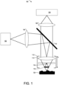
- the broadband light interferometer 100 includes a broadband light source 102.
- the use of broadband light reduces temporal coherence of the light for fringe-nulling purposes.
- the broadband light source 102 provides visible light.
- the wavelength band (e.g., color) of the light provided by the broadband light source 102 is adjustable. For example, light-emitting diodes (LEDs) and/or filters in the broadband light source 102 may be changed to change the wavelength band.
- the broadband light interferometer 100 may have multiple broadband light sources 102 that can be multiplexed into the optical path, each of which provides a different wavelength band.
- the objective 112 collects light from the photomask 120.
- the collected light and the reference light, which interfere, are collimated by the lens 114 and transmitted through the beamsplitter 110 to a tube lens 108, which focuses them onto a camera 106 (e.g., a digital camera).
- a camera 106 e.g., a digital camera
- the image (i.e., interferogram) produced in the camera 106 includes interference effects resulting from interference between the collected light from the photomask and the reference light.
- the interference effects vary as a function of the height of the objective 112 above the photomask 120.
- the height of the objective 112 above the photomask 120 is adjustable.
- the objective 112 may be on a z-scanning stage that can move the objective 112 up and down along the z-axis (i.e., adjust the z-height).
- the z-height can also be adjusted by moving the photomask under the objective with a z-scanning stage.
- interferograms Multiple images (i.e., interferograms) of the photomask 120 may be taken with the objective 112 at different heights (i.e., z-values) above the photomask 120, and the heights of respective areas on the surface of the photomask 120 may be determined by comparing the images, using interferogram analysis (e.g., known three-, four-, or five-step interferogram-based analysis algorithms).
- interferogram analysis e.g., known three-, four-, or five-step interferogram-based analysis algorithms.
- the heights measured for patterned areas on the surface of the photomask will be incorrect due to the three-dimensional electromagnetic effects, however, and therefore cannot be directly used to produce a focal map for defect inspection.
- NA 0.10
- a central wavelength of 500 nm for the broadband light source 102 which is an extended spatially incoherent light source
- the broadband light interferometer 100 observes an average effect of the dense patterns on the photomask 120 without resolving the features, such that only the zeroth-order diffracted light from the photomask 120 will interfere with the reference light. This effect results in incorrect height measurements.
- the error in the measured height varies as a function of the fill factor (e.g., defined as the area percentage not covered by absorber material 204, Figure 2 ) for a patterned area on the photomask 120.
- the following discussion describes techniques for determining corrections to apply to the incorrect height measurements, to produce height values that may be used in a focal map of defect inspection.
- the corrections may be determined based on the fill factors.
- the produced height values for the focal map are substantially pattern-independent: they depend on the fill-factor correction but not on the details of the patterns.
- the photomask 120 is for EUV (e.g., 13.5 nm) photolithography.
- the absorber material 204 absorbs the EUV (e.g., 13.5 nm) light and the multilayer material 202 partially reflects the EUV (e.g., 13.5 nm) light.
- the multilayer material 202 includes alternating layers of molybdenum (Mo) and silicon (Si) above a substrate (e.g., a blank photomask), with a capping layer covering the alternating layers of Mo and Si.
- the capping layer may be ruthenium (Ru) or boron (B). Each pair of adjacent Mo and Si layers is called a MoSi bilayer.
- the Mo layer thickness may be 2.8 nm
- the Si layer thickness may be 4.2 nm
- the capping layer thickness may be 2.5 nm.
- the number of MoSi bilayers in the multilayer material 202 may be 40 or more, or 35 or more.
- the absorber material 204 includes a tantalum boron nitride (TaBN) layer with a tantalum boron oxide (TaBO) capping layer above the TaBN layer.
- the TaBO capping layer has a thickness of 2 nm.
- the thickness of the TaBN layer 310 may be 70-80 nm.
- Figure 3 is a plan view of a pattern 300 on the surface of the photomask 120, illuminated by a spot 300 of light from the broadband light interferometer 100 ( Figure 1 ), in accordance with some embodiments.
- the pattern 300 includes regions in which the multilayer material 202 is exposed and regions in which the absorber material 204 covers the multilayer material 202.
- the pattern 300 is periodic. Focal-mapping techniques described herein do not require periodic patterning, however, and may also be used for photomasks with non-periodic (e.g., random) patterning.
- a patterned area such as the patterned area 200 ( Figure 2 ) or an area in the pattern 300 ( Figure 3 ) has a fill factor a equal to the fraction of the area 200 that is not covered by the absorber material 204 (i.e., a is the fill factor for the exposed multilayer material 202).
- E 1 r 0 is the reflected electric field off the absorber material 204 (which is not a perfect absorber, such that E 1 r 0 is non-zero) and E 2 r 0 is the reflected electric field off the multilayer material 202 (which is not a perfect reflector).
- the measured height i.e., the effective height obtained through broadband light interferometry, which is different from the actual height
- Figure 5 is a graph 500 showing calculated height-correction curves in accordance with some embodiments.
- the height correction curves show height corrections, which are to be applied to photomask heights measured using broadband light interferometry, versus the fill factor a (i.e., the ML 202 fill factor).
- the height correction curves are calculated in accordance with equations 3 and 4, and vary as a function of the phase change of light upon reflection by the multilayer material 202.
- Figure 5 shows a first curve 502 for a phase change of -20°, a second curve 504 for a zero-degree phase change, and a third curve 506 for a phase change of +20°.
- Application of the height corrections may produce a focal map that gives a trajectory for focusing the inspection optics on top of the absorber material 204, on top of the multilayer material 202 (i.e., at the bottom of the absorber material 204), or on any predetermined surface in between these two surfaces.
- Figure 6A shows a plan view of a height image of a photomask 120 and a corresponding curve showing heights in a cross-sectional profile 608 of the photomask 120, in accordance with some embodiments.
- the height image is generated by performing broadband light interferometry (e.g., using the broadband light interferometer 100, Figure 1 ) to generate interferograms with the objective (e.g., objective 112, Figure 1 ) at multiple respective heights (i.e., z-positions) above the photomask 120, and analyzing the interferograms to determine measured heights.
- broadband light interferometry e.g., using the broadband light interferometer 100, Figure 1
- the objective e.g., objective 112, Figure 1
- Heights in the patterned areas 606 similarly should step up and down by an amount equal to the height (i.e., thickness) of the absorber material 204, since the absorber material 204 is either present or absent at each point in the patterned areas 606.
- Broadband light interferometry is not able to resolve the features in the patterned areas 606 (e.g., because the patterning pitch is less than the resolution limit).
- the measured heights in the patterned areas 606 include intermediate values, which are incorrect.
- Raw heights as measured through broadband light interferometry therefore cannot be used for focal mapping.
- height corrections e.g., the height corrections of Figure 5
- the corrected heights may be used for focal mapping.
- the fill factors for respective photomask areas are first determined.
- the database of the design for the photomask is available and the fill factors are determined from the database (e.g., as in step 806 of the method 800, Figure 8 ).
- the fill factors can be determined based on average reflectivities.
- Each z-position (i.e., z-height) for the objective (or photomask) corresponds to a distinct phase index i.
- the coefficients a and b may be obtained through known analysis of the interferograms.
- of the reference-surface reflectivity r r and the testing-surface reflectivity r t is deduced, again through known interferometric analysis.
- the reference-surface reflectivity r r is a known property of the broadband light interferometer, and the amplitude (i.e., magnitude) of the testing-surface reflectivity r t is determined accordingly.
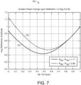
- Figure 7 is a graph 700 showing curves of average reflectivity amplitude versus fill factor a (i.e., versus the multilayer-material 202 fill factor) for different wavelength bands (e.g., colors), in accordance with some embodiments.
- the curves of the graph 700 are calculated and thus prophetic.
- the curves 702 and 704 are calculated assuming a zero-degree phase change upon reflection by the multilayer material 202 (e.g., as for the curve 504, Figure 5 ). Similar curves may be calculated for other phase changes.
- the reflectivity for a single wavelength band does not specify a single fill factor: the correlation between reflectivities and fill factors is not one-to-one.
- the correlation between reflectivities and fill factors is one-to-two (i.e., a respective reflectivity value corresponds to two fill factors).
- the broadband light interferometer 100 may be configured to generate interferograms using each of the two different wavelength bands (e.g., by changing LEDs in the broadband light source 102, changing filters in the broadband light source 102, or multiplexing multiple broadband light sources 102). Given the resulting reflectivity data, unique fill factors may be identified for respective photomask areas, using the curves 702 and 704.
- the heights include heights of patterned areas of the photomask (e.g., areas patterned with an absorber material 204 situated above a multilayer material 202, Figures 2-3 ).
- the broadband light interferometry uses visible light.
- a height image (e.g., as shown in Figures 6A-6B ) for the photomask is generated (804) using the broadband light interferometry.
- the height image may include measured heights for the entire photomask or a portion thereof.
- the height image may include measured heights for a cross-section of the photomask (e.g., for the profile 608, Figures 6A-6B ).
- the fill factors are determined (810) based on the reflectivities, using predetermined correspondences between reflectivities and fill factors for the plurality of wavelength bands (e.g., correspondences that are not one-to-one). For example, the fill factors are determined using correspondences like those shown in Figure 7 .
- the plurality of wavelength bands may include a first color and a second color.
- the predetermined correspondences may include a first correspondence between reflectivities and fill factors for the first color and a second correspondence between reflectivities and fill factors for the second color, with neither the first correspondence nor the second correspondence being one-to-one.
- step 820 This determination of fill factors based on reflectivities is performed, for example, for die-to-die inspection, in which the subsequent defect inspection of step 820 involves comparing results from inspecting a die area on the photomask to results from inspecting a reference photomask die area.
- a focal map is produced (812) from the measured heights on the surface of the photomask.
- Producing the focal map includes adjusting the measured heights of the patterned areas based on fill factors for the patterned areas.
- the height image is adjusted (814) to offset the measured heights of the patterned areas (e.g., including measured heights in a cross-section of the photomask, such as the cross-section for the profile 608, Figures 6A-6B ), based on the fill factors.
- Height corrections for respective measured heights of the patterned areas may be determined (816) based on the fill factors, using a predetermined correspondence between measured heights and fill factors (e.g., using a correspondence like those shown in Figure 5 ).
- the height corrections may be applied (818) to the respective measured heights (e.g., to produce a trajectory 610, Figure 6B ).
- the resulting focal map may be substantially pattern-independent (e.g., such that the light used for photomask inspection in step 820 is focused on the top of absorber material 204, on top of the multilayer material 202, or on any predetermined surface in between these two surfaces).
- the photomask is inspected (820) for defects, using the focal map (i.e., the photomask-inspection optics focus the light used to inspect the photomask in accordance with the focal map).
- ultraviolet (UV) light is used (822) to inspect the photomask.
- EUV extreme ultraviolet
- DUV deep ultraviolet
- EUV is a common, well-known and well-understood technical term that refers to light with wavelengths in the range of 280 nm down to 100 nm.
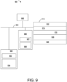
- the wavelength band used by the broadband light interferometer 932 may be variable (e.g., by multiplexing different light sources, using filters, or changing LEDs).
- the broadband light interferometer 932 may be configured to use multiple visible wavelength bands.
- the photomask-inspection optics 934 include ultraviolet optics, with corresponding ultraviolet light being used for defect inspection.
- the photomask-inspection optics 934 may include EUV optics (e.g., for 13.5 nm light) or DUV optics (e.g., for 193 nm light).
- the photomask-inspection system 900 also includes a computer system with one or more processors 902 (e.g., CPUs), optional user interfaces 906, memory 910, and one or more communication buses 904 interconnecting these components and the optics 930 (and other components of the photomask-inspection system 900 that are not shown, such as photomask-handling robotics).
- the user interfaces 906 may include a display 907 and one or more input devices 908 (e.g., a keyboard, mouse, touch-sensitive surface of the display 907, etc.).
- the display may show height images, focal maps, and defect-inspection data and may report the status of the photomask-inspection system 900 (e.g., the status of the method 800, Figure 8 ).
- Memory 910 includes volatile and/or non-volatile memory.
- Memory 910 (e.g., the non-volatile memory within memory 910) includes a non-transitory computer-readable storage medium.
- Memory 910 optionally includes one or more storage devices remotely located from the processor(s) 902 and/or a non-transitory computer-readable storage medium that is removably inserted into the computer system of the photomask-inspection system 900.
- memory 910 (e.g., the non-transitory computer-readable storage medium of memory 910) stores the following modules and data, or a subset or superset thereof: an operating system 912 that includes procedures for handling various basic system services and for performing hardware-dependent tasks, a broadband light interferometry (BLI) module 914 for controlling the broadband light interferometer 932, a focal-map production module 916, a defect-inspection module 918 for controlling photomask defect inspection using the photomask-inspection optics 934, and a reporting module 920 for reporting results from the modules 914, 916, and/or 918.
- an operating system 912 that includes procedures for handling various basic system services and for performing hardware-dependent tasks
- BBI broadband light interferometry
- the memory 910 (e.g., the non-transitory computer-readable storage medium of the memory 910) includes instructions for performing all or a portion of the method 800 ( Figure 8 ).
- Each of the modules stored in the memory 910 corresponds to a set of instructions for performing one or more functions described herein. Separate modules need not be implemented as separate software programs. The modules and various subsets of the modules may be combined or otherwise re-arranged. In some embodiments, the memory 910 stores a subset or superset of the modules and/or data structures identified above.
- Figure 9 is intended more as a functional description of the various features that may be present in the photomask-inspection system 900 than as a structural schematic.
- the functionality of the computer system of the photomask-inspection system 900 may be split between multiple devices.
- a portion of the modules stored in the memory 910 may alternatively be stored in one or more other computer systems communicatively coupled with the photomask-inspection system 900 through one or more networks.
Landscapes
- Physics & Mathematics (AREA)
- General Physics & Mathematics (AREA)
- General Health & Medical Sciences (AREA)
- Immunology (AREA)
- Life Sciences & Earth Sciences (AREA)
- Chemical & Material Sciences (AREA)
- Analytical Chemistry (AREA)
- Biochemistry (AREA)
- Pathology (AREA)
- Health & Medical Sciences (AREA)
- Spectroscopy & Molecular Physics (AREA)
- Engineering & Computer Science (AREA)
- Computer Vision & Pattern Recognition (AREA)
- Signal Processing (AREA)
- Length Measuring Devices By Optical Means (AREA)
- Investigating Materials By The Use Of Optical Means Adapted For Particular Applications (AREA)
- Instruments For Measurement Of Length By Optical Means (AREA)
Claims (15)
- Verfahren (800), umfassend:Messen von Höhen auf einer Fläche einer Fotomaske unter Verwendung von Breitband-Lichtinterferometrie, wobei die Höhen die Höhen gemusterter Bereiche der Fotomaske (802) umfassen;Erstellen einer Fokalkarte aus den gemessenen Höhen auf der Fläche der Fotomaske (812), umfassend Anpassen der gemessenen Höhen gemusterter Bereiche basierend auf Füllfaktoren für die gemusterten Bereiche, um dadurch eine korrigierte Fokalkarte zu erstellen; undPrüfung der Fotomaske auf Fehler mit einer Fotomasken-Kontrolloptik unter Verwendung der korrigierten Fokalkarte (820).
- Verfahren nach Anspruch 1, wobeidas Messen Erzeugen eines Höhenbildes für die Fotomaske unter Verwendung der Breitband-Lichtinterferometrie (804) umfasst; unddas Anpassen das Anpassen des Höhenbildes zum Versetzen der gemessenen Höhen gemusterter Bereiche basierend auf den Füllfaktoren (814) umfasst.
- Verfahren nach Anspruch 1, wobei:die Breitband-Lichtinterferometrie sichtbares Licht verwendet; unddas Prüfung der Fotomaske auf Fehler unter Verwendung von Ultraviolettlicht durchgeführt wird.
- Verfahren nach Anspruch 3, wobei das Ultraviolettlicht 13,5 nm Licht ist; oder wobei das Ultraviolettlicht 193 nm Licht ist.
- Verfahren nach Anspruch 1, wobei die Breitband-Lichtinterferometrie eine Mirau-Interferometrie ist; oder wobei die Breitband-Lichtinterferometrie eine Michelson-Interferometrie ist.
- Verfahren nach Anspruch 1, ferner umfassend Berechnen der Füllfaktoren basierend auf einer Datenbank des Entwurfs für die Fotomaske; oderferner umfassend das Berechnen der Füllfaktoren basierend auf einer Datenbank des Entwurfs für die Fotomaske; undwobei das Anpassen der gemessenen Höhen Folgendes umfasst:Bestimmen von Höhenkorrekturen für die jeweiligen gemessenen Höhen gemusterter Bereiche basierend auf den Füllfaktoren unter Verwendung einer vorbestimmten Entsprechung zwischen gemessenen Höhen und Füllfaktoren (816); undAnwenden der Höhenkorrekturen auf die jeweiligen gemessenen Höhen (818).
- Verfahren nach Anspruch 1, ferner umfassend:Bestimmuen von Reflektivitäten der gemusterten Bereiche basierend auf der Breitband-Lichtinterferometrie, wobei die Breitband-Lichtinterferometrie jeweilige Instanzen von Breitband-Lichtinterferometrie umfasst, die unter Verwendung jeweiliger Wellenlängenbänder einer Vielzahl von Wellenlängenbändern (808) durchgeführt werden; undBestimmen der Füllfaktoren basierend auf den Reflektivitäten unter Verwendung vorgegebener Entsprechungen zwischen Reflektivitäten und Füllfaktoren für die Vielzahl von Wellenlängenbändern (810);wobei das Anpassen der gemessenen Höhen Folgendes umfasst:Bestimmen von Höhenkorrekturen für die jeweiligen gemessenen Höhen gemusterter Bereiche basierend auf den Füllfaktoren unter Verwendung einer vorbestimmten Entsprechung zwischen gemessenen Höhen und Füllfaktoren (816); undAnwenden der Höhenkorrekturen auf die jeweiligen gemessenen Höhen (818); oderferner umfassend:Bestimmuen von Reflektivitäten der gemusterten Bereiche basierend auf der Breitband-Lichtinterferometrie, wobei die Breitband-Lichtinterferometrie jeweilige Instanzen von Breitband-Lichtinterferometrie umfasst, die unter Verwendung jeweiliger Wellenlängenbänder einer Vielzahl von Wellenlängenbändern durchgeführt werden; undBestimmen der Füllfaktoren basierend auf den Reflektivitäten unter Verwendung vorgegebener Entsprechungen zwischen Reflektivitäten und Füllfaktoren für die Vielzahl von Wellenlängenbändern;wobei das Anpassen der gemessenen Höhen Folgendes umfasst:Bestimmen von Höhenkorrekturen für die jeweiligen gemessenen Höhen gemusterter Bereiche basierend auf den Füllfaktoren unter Verwendung einer vorbestimmten Entsprechung zwischen gemessenen Höhen und Füllfaktoren; undAnwenden der Höhenkorrekturen auf die jeweiligen gemessenen Höhen; undwobei:die Vielzahl von Wellenlängenbändern eine erste und eine zweite Farbe umfasst;die vorbestimmten Entsprechungen eine erste Entsprechung zwischen Reflexionen und Füllfaktoren für die erste Farbe und eine zweite Entsprechung zwischen Reflexionen und Füllfaktoren für die zweite Farbe umfassen; undweder die erste noch die zweite Entsprechung eins-zu-eins ist.
- Photomasken-Kontrollsystem (900), umfassend:ein Breitband-Lichtinterferometer (932);eine Fotomasken-Kontrolloptik (930);einen oder mehrere Prozessoren (902); undSpeicher (910) zum Speichern eines oder mehrerer Programme zur Ausführung durch einen oder mehrere Prozessoren, wobei das eine oder die mehreren Programme Anweisungen zu Folgendem umfassen:Messen von Höhen auf einer Fläche einer Fotomaske unter Verwendung des Breitband-Lichtinterferometers, wobei die Höhen die Höhen gemusterter Bereiche der Fotomaske umfassen;Erstellen einer Fokalkarte aus den gemessenen Höhen auf der Fläche der Fotomaske, umfassend Anpassen der gemessenen Höhen gemusterter Bereiche basierend auf Füllfaktoren für die gemusterten Bereiche, um dadurch eine korrigierte Fokalkarte zu erstellen; undPrüfung der Fotomaske auf Fehler mit einer Fotomasken-Kontrolloptik unter Verwendung der korrigierten Fokalkarte.
- Fotomasken-Kontrollsystem nach Anspruch 8, wobei:die Anweisungen zum Messen der Höhen Anweisungen zum Erzeugen eines Höhenbildes für die Fotomaske unter Verwendung des Breitband-Lichtinterferometers umfassen; unddie Anweisungen zum Anpassen der gemessenen Höhen Anweisungen zum Anpassen des Höhenbildes zum Versetzen der gemessenen Höhen gemusterter Bereiche basierend auf den Füllfaktoren umfassen.
- Fotomasken-Kontrollsystem nach Anspruch 8, wobei:das Breitband-Lichtinterferometer (932) ein Sichtlichtinterferometer ist; unddie Fotomasken-Kontrolloptik eine 13,5 nm Optik umfasst; oderdie Fotomasken-Kontrolloptik eine 193 nm Optik umfasst.
- Fotomasken-Kontrollsystem nach Anspruch 8, wobei das Breitband-Lichtinterferometer (932) ein Mirau-Interferometer ist; oder wobei das Breitband-Lichtinterferometer ein Michelson-Interferometer ist.
- Fotomasken-Kontrollsystem nach Anspruch 8, wobei das eine oder die mehreren Programme ferner Anweisungen zum Berechnen der Füllfaktoren basierend auf einer Datenbank des Entwurfs für die Fotomaske umfassen; oderwobei das eine oder die mehreren Programme ferner Anweisungen zum Berechnen der Füllfaktoren basierend auf einer Datenbank des Entwurfs für die Fotomaske umfassen; undwobei die Anweisungen zum Anpassen der gemessenen Höhen Folgendes umfassen:Anweisungen zum Bestimmen von Höhenkorrekturen für die jeweiligen gemessenen Höhen gemusterter Bereiche basierend auf den Füllfaktoren unter Verwendung einer vorbestimmten Entsprechung zwischen gemessenen Höhen und Füllfaktoren; undAnweisungen zum Anwenden der Höhenkorrekturen auf die jeweiligen gemessenen Höhen.
- Fotomasken-Kontrollsystem nach Anspruch 8, wobei:
das eine oder die mehreren Programme ferner Anweisungen zu Folgendem umfassen:Bestimmuen von Reflektivitäten der gemusterten Bereiche basierend auf der Breitband-Lichtinterferometrie, wobei die Breitband-Lichtinterferometrie jeweilige Instanzen von Breitband-Lichtinterferometrie umfasst, die unter Verwendung jeweiliger Wellenlängenbänder einer Vielzahl von Wellenlängenbändern durchgeführt werden; undBestimmen der Füllfaktoren basierend auf den Reflektivitäten unter Verwendung vorgegebener Entsprechungen zwischen Reflektivitäten und Füllfaktoren für die Vielzahl von Wellenlängenbändern; und die Anweisungen zum Anpassen der gemessenen Höhen Anweisungen zu Folgendem umfassen:Bestimmen von Höhenkorrekturen für die jeweiligen gemessenen Höhen gemusterter Bereiche basierend auf den Füllfaktoren unter Verwendung einer vorbestimmten Entsprechung zwischen gemessenen Höhen und Füllfaktoren; undAnwenden der Höhenkorrekturen auf die jeweiligen gemessenen Höhen. - Fotomasken-Kontrollsystem nach Anspruch 13, wobei:die Vielzahl von Wellenlängenbändern eine erste und eine zweite Farbe umfasst;die vorbestimmten Entsprechungen eine erste Entsprechung zwischen Reflexionen und Füllfaktoren für die erste Farbe und eine zweite Entsprechung zwischen Reflexionen und Füllfaktoren für die zweite Farbe umfassen; undweder die erste noch die zweite Entsprechung eins-zu-eins ist.
- Nichtflüchtiges computerlesbares Speichermedium, das ein oder mehrere Programme zur Ausführung durch einen oder mehrere Prozessoren eines Fotomasken-Kontrollsystems speichert, das ferner ein Breitband-Lichtinterferometer und eine Fotomasken-Kontrolloptik umfasst, wobei das eine oder die mehreren Programme Anweisungen zu Folgendem beinhalten:Messen von Höhen auf einer Fläche einer Fotomaske unter Verwendung von Breitband-Lichtinterferometrie, wobei die Höhen die Höhen gemusterter Bereiche der Fotomaske umfassen;Erstellen einer Fokalkarte aus den gemessenen Höhen auf der Fläche der Fotomaske, umfassend Anpassen der gemessenen Höhen gemusterter Bereiche basierend auf Füllfaktoren für die gemusterten Bereiche, um dadurch eine korrigierte Fokalkarte zu erstellen; undPrüfung der Fotomaske auf Fehler mit einer Fotomasken-Kontrolloptik unter Verwendung der korrigierten Fokalkarte.
Applications Claiming Priority (3)
| Application Number | Priority Date | Filing Date | Title |
|---|---|---|---|
| US201962914350P | 2019-10-11 | 2019-10-11 | |
| US17/063,622 US11442021B2 (en) | 2019-10-11 | 2020-10-05 | Broadband light interferometry for focal-map generation in photomask inspection |
| PCT/US2020/055173 WO2021072343A1 (en) | 2019-10-11 | 2020-10-11 | Broadband light interferometry for focal-map generation in photomask inspection |
Publications (3)
| Publication Number | Publication Date |
|---|---|
| EP4042144A1 EP4042144A1 (de) | 2022-08-17 |
| EP4042144A4 EP4042144A4 (de) | 2023-10-18 |
| EP4042144B1 true EP4042144B1 (de) | 2025-04-16 |
Family
ID=75382118
Family Applications (1)
| Application Number | Title | Priority Date | Filing Date |
|---|---|---|---|
| EP20873642.1A Active EP4042144B1 (de) | 2019-10-11 | 2020-10-11 | Breitband-lichtinterferometrie zur fokalkartenerzeugung bei der fotomaskenkontrolle |
Country Status (6)
| Country | Link |
|---|---|
| US (1) | US11442021B2 (de) |
| EP (1) | EP4042144B1 (de) |
| JP (1) | JP7429775B2 (de) |
| KR (1) | KR102629850B1 (de) |
| TW (1) | TWI829969B (de) |
| WO (1) | WO2021072343A1 (de) |
Families Citing this family (3)
| Publication number | Priority date | Publication date | Assignee | Title |
|---|---|---|---|---|
| US12360058B2 (en) * | 2020-12-21 | 2025-07-15 | Kla Corporation | Integration of an optical height sensor in mask inspection tools |
| US11815810B2 (en) | 2021-09-22 | 2023-11-14 | Intel Corporation | Measurement tool and methods for EUV lithography masks |
| WO2024116674A1 (ja) * | 2022-11-29 | 2024-06-06 | パナソニックIpマネジメント株式会社 | 検査システム |
Family Cites Families (42)
| Publication number | Priority date | Publication date | Assignee | Title |
|---|---|---|---|---|
| US4340306A (en) * | 1980-02-04 | 1982-07-20 | Balasubramanian N | Optical system for surface topography measurement |
| JPH0795623B2 (ja) * | 1989-05-12 | 1995-10-11 | ジューキ株式会社 | 直接描画装置における基板表面計測方法 |
| JP3477777B2 (ja) * | 1993-01-22 | 2003-12-10 | 株式会社日立製作所 | 投影露光装置およびその方法 |
| US5706084A (en) * | 1995-09-14 | 1998-01-06 | The United States Of America As Represented By The Administrator Of The National Aeronautics And Space Administration | Modulated source interferometry with combined amputude & frequency modulation |
| US5987189A (en) * | 1996-12-20 | 1999-11-16 | Wyko Corporation | Method of combining multiple sets of overlapping surface-profile interferometric data to produce a continuous composite map |
| US5748323A (en) * | 1997-01-23 | 1998-05-05 | Advanced Micro Devices | Method and apparatus for wafer-focusing |
| US6324298B1 (en) * | 1998-07-15 | 2001-11-27 | August Technology Corp. | Automated wafer defect inspection system and a process of performing such inspection |
| US6184992B1 (en) | 1999-02-09 | 2001-02-06 | Phase Metrics, Inc. | Apparatus and method for measuring flying height and a real index of refraction |
| US6160621A (en) * | 1999-09-30 | 2000-12-12 | Lam Research Corporation | Method and apparatus for in-situ monitoring of plasma etch and deposition processes using a pulsed broadband light source |
| US6771607B1 (en) * | 2000-06-30 | 2004-08-03 | Raymond Philip Russell | Measure and recording of traffic parameters in data transmission networks |
| EP1231513A1 (de) * | 2001-02-08 | 2002-08-14 | Asm Lithography B.V. | Lithographischer Projektionsapparat mit verstellbarer Abbildungsfläche |
| DE10155112B4 (de) * | 2001-11-09 | 2006-02-02 | Infineon Technologies Ag | Reflexionsmaske für die EUV-Lithographie und Herstellungsverfahren dafür |
| US6844272B2 (en) * | 2002-03-01 | 2005-01-18 | Euv Limited Liability Corporation | Correction of localized shape errors on optical surfaces by altering the localized density of surface or near-surface layers |
| US7473911B2 (en) * | 2002-07-30 | 2009-01-06 | Applied Materials, Israel, Ltd. | Specimen current mapper |
| WO2004099877A1 (de) * | 2003-05-12 | 2004-11-18 | Carl Zeiss Smt Ag | Optische messvorrichtung und betriebsverfahren für ein optisches abbildungssystem |
| US7303841B2 (en) * | 2004-03-26 | 2007-12-04 | Taiwan Semiconductor Manufacturing Company | Repair of photolithography masks by sub-wavelength artificial grating technology |
| US20050254065A1 (en) * | 2004-05-12 | 2005-11-17 | Stokowski Stanley E | Method and apparatus for detecting surface characteristics on a mask blank |
| US7433058B2 (en) * | 2004-07-12 | 2008-10-07 | Solvision Inc. | System and method for simultaneous 3D height measurements on multiple sides of an object |
| US7884947B2 (en) * | 2005-01-20 | 2011-02-08 | Zygo Corporation | Interferometry for determining characteristics of an object surface, with spatially coherent illumination |
| US7564017B2 (en) * | 2005-06-03 | 2009-07-21 | Brion Technologies, Inc. | System and method for characterizing aerial image quality in a lithography system |
| US7749666B2 (en) * | 2005-08-09 | 2010-07-06 | Asml Netherlands B.V. | System and method for measuring and analyzing lithographic parameters and determining optimal process corrections |
| JP2009509149A (ja) * | 2005-09-22 | 2009-03-05 | ローベルト ボツシユ ゲゼルシヤフト ミツト ベシユレンクテル ハフツング | 干渉計による層厚決定 |
| US20080151204A1 (en) * | 2006-12-21 | 2008-06-26 | Asml Netherlands B.V. | Method for positioning a target portion of a substrate with respect to a focal plane of a projection system |
| US7835015B1 (en) * | 2007-03-05 | 2010-11-16 | Kla-Tencor Corporation | Auto focus system for reticle inspection |
| JP2009003322A (ja) | 2007-06-25 | 2009-01-08 | Sii Nanotechnology Inc | フォトマスク欠陥修正装置及びフォトマスク欠陥修正方法 |
| US8175373B2 (en) * | 2009-02-16 | 2012-05-08 | Kla-Tencor Corporation | Use of design information and defect image information in defect classification |
| EP2314982B1 (de) * | 2009-10-20 | 2020-12-02 | Mitutoyo Corporation | Verfahren und Vorrichtung zur Bestimmung der Höhe einer Reihe räumlicher Positionen auf einer Probe, die ein Profil einer Oberfläche mithilfe der Weißlicht-Interferometrie definieren |
| JP2012078164A (ja) * | 2010-09-30 | 2012-04-19 | Nuflare Technology Inc | パターン検査装置 |
| JP2012127682A (ja) | 2010-12-13 | 2012-07-05 | Hitachi High-Technologies Corp | 欠陥検査方法及びその装置 |
| CN104220932B (zh) | 2012-02-21 | 2017-02-22 | Asml荷兰有限公司 | 检查设备和方法 |
| JP6025419B2 (ja) * | 2012-06-27 | 2016-11-16 | 株式会社ニューフレアテクノロジー | 検査方法および検査装置 |
| JP5840584B2 (ja) * | 2012-09-06 | 2016-01-06 | 株式会社東芝 | 露光装置、露光方法および半導体装置の製造方法 |
| WO2014104276A1 (ja) * | 2012-12-28 | 2014-07-03 | Hoya株式会社 | マスクブランク用基板、多層反射膜付き基板、反射型マスクブランク、反射型マスク、マスクブランク用基板の製造方法及び多層反射膜付き基板の製造方法並びに半導体装置の製造方法 |
| US9110039B2 (en) | 2013-07-25 | 2015-08-18 | Kla-Tencor Corporation | Auto-focus system and methods for die-to-die inspection |
| KR102211093B1 (ko) * | 2014-02-12 | 2021-02-03 | 에이에스엠엘 네델란즈 비.브이. | 프로세스 윈도우를 최적화하는 방법 |
| JP5767357B1 (ja) * | 2014-03-26 | 2015-08-19 | Hoya株式会社 | マスクブランク用基板、マスクブランク及び転写用マスク、並びにそれらの製造方法 |
| US9746315B1 (en) * | 2014-06-02 | 2017-08-29 | Bruker Nano Inc. | Side illumination in interferometry |
| US10025079B2 (en) * | 2015-09-28 | 2018-07-17 | Kenneth Carlisle Johnson | Actinic, spot-scanning microscope for EUV mask inspection and metrology |
| US10451563B2 (en) * | 2017-02-21 | 2019-10-22 | Kla-Tencor Corporation | Inspection of photomasks by comparing two photomasks |
| NL2021024A (en) * | 2017-06-14 | 2018-12-19 | Asml Netherlands Bv | Lithographic Apparatus and Method |
| US11048163B2 (en) * | 2017-11-07 | 2021-06-29 | Taiwan Semiconductor Manufacturing Company, Ltd. | Inspection method of a photomask and an inspection system |
| KR102735767B1 (ko) * | 2018-08-02 | 2024-11-28 | 코닝 인코포레이티드 | 중력으로 인한 에러가 감소된 포토마스크의 평탄도를 측정하는 시스템 및 방법 |
-
2020
- 2020-10-05 US US17/063,622 patent/US11442021B2/en active Active
- 2020-10-08 TW TW109134920A patent/TWI829969B/zh active
- 2020-10-11 KR KR1020227014843A patent/KR102629850B1/ko active Active
- 2020-10-11 JP JP2022521148A patent/JP7429775B2/ja active Active
- 2020-10-11 WO PCT/US2020/055173 patent/WO2021072343A1/en not_active Ceased
- 2020-10-11 EP EP20873642.1A patent/EP4042144B1/de active Active
Also Published As
| Publication number | Publication date |
|---|---|
| JP7429775B2 (ja) | 2024-02-08 |
| TWI829969B (zh) | 2024-01-21 |
| WO2021072343A1 (en) | 2021-04-15 |
| KR20220075406A (ko) | 2022-06-08 |
| TW202129253A (zh) | 2021-08-01 |
| KR102629850B1 (ko) | 2024-01-25 |
| EP4042144A1 (de) | 2022-08-17 |
| EP4042144A4 (de) | 2023-10-18 |
| US11442021B2 (en) | 2022-09-13 |
| JP2022553636A (ja) | 2022-12-26 |
| US20210109030A1 (en) | 2021-04-15 |
Similar Documents
| Publication | Publication Date | Title |
|---|---|---|
| JP6618551B2 (ja) | 検査装置、検査方法、リソグラフィ装置、パターニングデバイス及び製造方法 | |
| US10067068B2 (en) | Lithographic apparatus and method for performing a measurement | |
| US11442021B2 (en) | Broadband light interferometry for focal-map generation in photomask inspection | |
| US20240288782A1 (en) | Metrology method and associated metrology tool | |
| US12158435B2 (en) | Illumination and detection apparatus for a metrology apparatus | |
| US12360058B2 (en) | Integration of an optical height sensor in mask inspection tools | |
| EP4187321A1 (de) | Metrologisches verfahren und zugehöriges metrologisches werkzeug | |
| US20200363727A1 (en) | Metrology Tools Comprising Aplanatic Objective Singlet | |
| US12566406B2 (en) | Dark field digital holographic microscope and associated metrology method | |
| US20250191170A1 (en) | System and method for overlay metrology using a phase mask | |
| WO2025131523A1 (en) | Metrology method for a digital holographic microscope and associated computer program | |
| NL2023157A (en) | Metrology tools comprising aplanatic objective singlet |
Legal Events
| Date | Code | Title | Description |
|---|---|---|---|
| STAA | Information on the status of an ep patent application or granted ep patent |
Free format text: STATUS: THE INTERNATIONAL PUBLICATION HAS BEEN MADE |
|
| PUAI | Public reference made under article 153(3) epc to a published international application that has entered the european phase |
Free format text: ORIGINAL CODE: 0009012 |
|
| STAA | Information on the status of an ep patent application or granted ep patent |
Free format text: STATUS: REQUEST FOR EXAMINATION WAS MADE |
|
| 17P | Request for examination filed |
Effective date: 20220426 |
|
| AK | Designated contracting states |
Kind code of ref document: A1 Designated state(s): AL AT BE BG CH CY CZ DE DK EE ES FI FR GB GR HR HU IE IS IT LI LT LU LV MC MK MT NL NO PL PT RO RS SE SI SK SM TR |
|
| DAV | Request for validation of the european patent (deleted) | ||
| DAX | Request for extension of the european patent (deleted) | ||
| P01 | Opt-out of the competence of the unified patent court (upc) registered |
Effective date: 20230526 |
|
| A4 | Supplementary search report drawn up and despatched |
Effective date: 20230920 |
|
| RIC1 | Information provided on ipc code assigned before grant |
Ipc: G03F 1/84 20120101ALI20230914BHEP Ipc: G01N 21/956 20060101ALI20230914BHEP Ipc: G01N 21/95 20060101ALI20230914BHEP Ipc: G01N 21/88 20060101ALI20230914BHEP Ipc: G01N 21/45 20060101AFI20230914BHEP |
|
| GRAP | Despatch of communication of intention to grant a patent |
Free format text: ORIGINAL CODE: EPIDOSNIGR1 |
|
| STAA | Information on the status of an ep patent application or granted ep patent |
Free format text: STATUS: GRANT OF PATENT IS INTENDED |
|
| INTG | Intention to grant announced |
Effective date: 20241107 |
|
| GRAS | Grant fee paid |
Free format text: ORIGINAL CODE: EPIDOSNIGR3 |
|
| GRAA | (expected) grant |
Free format text: ORIGINAL CODE: 0009210 |
|
| STAA | Information on the status of an ep patent application or granted ep patent |
Free format text: STATUS: THE PATENT HAS BEEN GRANTED |
|
| AK | Designated contracting states |
Kind code of ref document: B1 Designated state(s): AL AT BE BG CH CY CZ DE DK EE ES FI FR GB GR HR HU IE IS IT LI LT LU LV MC MK MT NL NO PL PT RO RS SE SI SK SM TR |
|
| REG | Reference to a national code |
Ref country code: GB Ref legal event code: FG4D |
|
| REG | Reference to a national code |
Ref country code: CH Ref legal event code: EP |
|
| REG | Reference to a national code |
Ref country code: IE Ref legal event code: FG4D |
|
| REG | Reference to a national code |
Ref country code: DE Ref legal event code: R096 Ref document number: 602020049706 Country of ref document: DE |
|
| REG | Reference to a national code |
Ref country code: NL Ref legal event code: FP |
|
| REG | Reference to a national code |
Ref country code: AT Ref legal event code: MK05 Ref document number: 1786003 Country of ref document: AT Kind code of ref document: T Effective date: 20250416 |
|
| PG25 | Lapsed in a contracting state [announced via postgrant information from national office to epo] |
Ref country code: PT Free format text: LAPSE BECAUSE OF FAILURE TO SUBMIT A TRANSLATION OF THE DESCRIPTION OR TO PAY THE FEE WITHIN THE PRESCRIBED TIME-LIMIT Effective date: 20250818 Ref country code: FI Free format text: LAPSE BECAUSE OF FAILURE TO SUBMIT A TRANSLATION OF THE DESCRIPTION OR TO PAY THE FEE WITHIN THE PRESCRIBED TIME-LIMIT Effective date: 20250416 Ref country code: ES Free format text: LAPSE BECAUSE OF FAILURE TO SUBMIT A TRANSLATION OF THE DESCRIPTION OR TO PAY THE FEE WITHIN THE PRESCRIBED TIME-LIMIT Effective date: 20250416 |
|
| REG | Reference to a national code |
Ref country code: LT Ref legal event code: MG9D |
|
| PG25 | Lapsed in a contracting state [announced via postgrant information from national office to epo] |
Ref country code: GR Free format text: LAPSE BECAUSE OF FAILURE TO SUBMIT A TRANSLATION OF THE DESCRIPTION OR TO PAY THE FEE WITHIN THE PRESCRIBED TIME-LIMIT Effective date: 20250717 Ref country code: NO Free format text: LAPSE BECAUSE OF FAILURE TO SUBMIT A TRANSLATION OF THE DESCRIPTION OR TO PAY THE FEE WITHIN THE PRESCRIBED TIME-LIMIT Effective date: 20250716 |
|
| PG25 | Lapsed in a contracting state [announced via postgrant information from national office to epo] |
Ref country code: PL Free format text: LAPSE BECAUSE OF FAILURE TO SUBMIT A TRANSLATION OF THE DESCRIPTION OR TO PAY THE FEE WITHIN THE PRESCRIBED TIME-LIMIT Effective date: 20250416 |
|
| PG25 | Lapsed in a contracting state [announced via postgrant information from national office to epo] |
Ref country code: BG Free format text: LAPSE BECAUSE OF FAILURE TO SUBMIT A TRANSLATION OF THE DESCRIPTION OR TO PAY THE FEE WITHIN THE PRESCRIBED TIME-LIMIT Effective date: 20250416 |
|
| PG25 | Lapsed in a contracting state [announced via postgrant information from national office to epo] |
Ref country code: HR Free format text: LAPSE BECAUSE OF FAILURE TO SUBMIT A TRANSLATION OF THE DESCRIPTION OR TO PAY THE FEE WITHIN THE PRESCRIBED TIME-LIMIT Effective date: 20250416 |
|
| PG25 | Lapsed in a contracting state [announced via postgrant information from national office to epo] |
Ref country code: AT Free format text: LAPSE BECAUSE OF FAILURE TO SUBMIT A TRANSLATION OF THE DESCRIPTION OR TO PAY THE FEE WITHIN THE PRESCRIBED TIME-LIMIT Effective date: 20250416 |
|
| PG25 | Lapsed in a contracting state [announced via postgrant information from national office to epo] |
Ref country code: RS Free format text: LAPSE BECAUSE OF FAILURE TO SUBMIT A TRANSLATION OF THE DESCRIPTION OR TO PAY THE FEE WITHIN THE PRESCRIBED TIME-LIMIT Effective date: 20250716 |
|
| PG25 | Lapsed in a contracting state [announced via postgrant information from national office to epo] |
Ref country code: IS Free format text: LAPSE BECAUSE OF FAILURE TO SUBMIT A TRANSLATION OF THE DESCRIPTION OR TO PAY THE FEE WITHIN THE PRESCRIBED TIME-LIMIT Effective date: 20250816 |
|
| PG25 | Lapsed in a contracting state [announced via postgrant information from national office to epo] |
Ref country code: LV Free format text: LAPSE BECAUSE OF FAILURE TO SUBMIT A TRANSLATION OF THE DESCRIPTION OR TO PAY THE FEE WITHIN THE PRESCRIBED TIME-LIMIT Effective date: 20250416 |
|
| PGFP | Annual fee paid to national office [announced via postgrant information from national office to epo] |
Ref country code: NL Payment date: 20251026 Year of fee payment: 6 |
|
| PGFP | Annual fee paid to national office [announced via postgrant information from national office to epo] |
Ref country code: DE Payment date: 20251029 Year of fee payment: 6 |
|
| PG25 | Lapsed in a contracting state [announced via postgrant information from national office to epo] |
Ref country code: SM Free format text: LAPSE BECAUSE OF FAILURE TO SUBMIT A TRANSLATION OF THE DESCRIPTION OR TO PAY THE FEE WITHIN THE PRESCRIBED TIME-LIMIT Effective date: 20250416 Ref country code: DK Free format text: LAPSE BECAUSE OF FAILURE TO SUBMIT A TRANSLATION OF THE DESCRIPTION OR TO PAY THE FEE WITHIN THE PRESCRIBED TIME-LIMIT Effective date: 20250416 |
|
| REG | Reference to a national code |
Ref country code: DE Ref legal event code: R097 Ref document number: 602020049706 Country of ref document: DE |
|
| PG25 | Lapsed in a contracting state [announced via postgrant information from national office to epo] |
Ref country code: CZ Free format text: LAPSE BECAUSE OF FAILURE TO SUBMIT A TRANSLATION OF THE DESCRIPTION OR TO PAY THE FEE WITHIN THE PRESCRIBED TIME-LIMIT Effective date: 20250416 |
|
| PG25 | Lapsed in a contracting state [announced via postgrant information from national office to epo] |
Ref country code: EE Free format text: LAPSE BECAUSE OF FAILURE TO SUBMIT A TRANSLATION OF THE DESCRIPTION OR TO PAY THE FEE WITHIN THE PRESCRIBED TIME-LIMIT Effective date: 20250416 |
|
| PG25 | Lapsed in a contracting state [announced via postgrant information from national office to epo] |
Ref country code: SK Free format text: LAPSE BECAUSE OF FAILURE TO SUBMIT A TRANSLATION OF THE DESCRIPTION OR TO PAY THE FEE WITHIN THE PRESCRIBED TIME-LIMIT Effective date: 20250416 |
|
| PG25 | Lapsed in a contracting state [announced via postgrant information from national office to epo] |
Ref country code: IT Free format text: LAPSE BECAUSE OF FAILURE TO SUBMIT A TRANSLATION OF THE DESCRIPTION OR TO PAY THE FEE WITHIN THE PRESCRIBED TIME-LIMIT Effective date: 20250416 |
|
| PG25 | Lapsed in a contracting state [announced via postgrant information from national office to epo] |
Ref country code: RO Free format text: LAPSE BECAUSE OF FAILURE TO SUBMIT A TRANSLATION OF THE DESCRIPTION OR TO PAY THE FEE WITHIN THE PRESCRIBED TIME-LIMIT Effective date: 20250416 |
|
| PLBE | No opposition filed within time limit |
Free format text: ORIGINAL CODE: 0009261 |
|
| STAA | Information on the status of an ep patent application or granted ep patent |
Free format text: STATUS: NO OPPOSITION FILED WITHIN TIME LIMIT |
|
| REG | Reference to a national code |
Ref country code: CH Ref legal event code: L10 Free format text: ST27 STATUS EVENT CODE: U-0-0-L10-L00 (AS PROVIDED BY THE NATIONAL OFFICE) Effective date: 20260225 |
|
| 26N | No opposition filed |
Effective date: 20260119 |