EP4042097B1 - Lawinenauslösesystem - Google Patents
Lawinenauslösesystem Download PDFInfo
- Publication number
- EP4042097B1 EP4042097B1 EP20793766.5A EP20793766A EP4042097B1 EP 4042097 B1 EP4042097 B1 EP 4042097B1 EP 20793766 A EP20793766 A EP 20793766A EP 4042097 B1 EP4042097 B1 EP 4042097B1
- Authority
- EP
- European Patent Office
- Prior art keywords
- unit
- triggering system
- explosion
- flexible envelope
- portable unit
- Prior art date
- Legal status (The legal status is an assumption and is not a legal conclusion. Google has not performed a legal analysis and makes no representation as to the accuracy of the status listed.)
- Active
Links
Images

Classifications
-
- F—MECHANICAL ENGINEERING; LIGHTING; HEATING; WEAPONS; BLASTING
- F42—AMMUNITION; BLASTING
- F42D—BLASTING
- F42D3/00—Particular applications of blasting techniques
-
- E—FIXED CONSTRUCTIONS
- E01—CONSTRUCTION OF ROADS, RAILWAYS, OR BRIDGES
- E01F—ADDITIONAL WORK, SUCH AS EQUIPPING ROADS OR THE CONSTRUCTION OF PLATFORMS, HELICOPTER LANDING STAGES, SIGNS, SNOW FENCES, OR THE LIKE
- E01F7/00—Devices affording protection against snow, sand drifts, side-wind effects, snowslides, avalanches or falling rocks; Anti-dazzle arrangements ; Sight-screens for roads, e.g. to mask accident site
- E01F7/04—Devices affording protection against snowslides, avalanches or falling rocks, e.g. avalanche preventing structures, galleries
-
- F—MECHANICAL ENGINEERING; LIGHTING; HEATING; WEAPONS; BLASTING
- F42—AMMUNITION; BLASTING
- F42D—BLASTING
- F42D1/00—Blasting methods or apparatus, e.g. loading or tamping
Definitions
- the present invention relates to the field of preventive triggering of avalanches and more particularly relates to an avalanche triggering system as for example described in the document FR2771168 A .
- the preventive triggering of avalanches mainly aims to secure ski areas, traffic networks, or even homes.
- the snow cover that forms on the slope of a wall includes a set of layers of snow deposited on top of each other as precipitation occurs. These different layers are often made up of different types of snow, hence a certain heterogeneity of the snow cover, often the cause of the avalanche.
- the preventive triggering of avalanches consists of causing a shock wave on a higher zone of the surface of the snow cover in such a way as to cause a disruption of the balance of the snow cover in this zone, and this before the accumulation of snow can cause a destructive natural avalanche.
- a first known technique consists of having an operator place explosive charges at the precise location where the avalanche is to be triggered. This placement can be done either from a helicopter by throwing, or from the ground, the explosive charge can then be deposited, slid or launched at the appropriate location. The igniting of the charge, in both cases, is generally obtained by slow wick or electrically. The risks inherent in this technique are significant. In addition to the risks directly linked to the handling of explosives, the operator must, to place explosive charges directly on the ground, go to often steep areas with unstable snow cover.
- Remote triggering techniques have been put in place.
- Remote initiation techniques use military weapons such as rocket launchers or shell launchers to cause the explosion on site.
- This type of device is not suitable for certain legislation, such as French legislation, which prohibits the storage of primed charges.
- One way to reduce the risks associated with handling explosives is to use explosive gases to generate a shock wave used to trigger the avalanche.
- the document FR2636729 describes a remote avalanche triggering system which operates without explosive materials and which is known under the trade mark Gazex ® .
- Such a system comprises a barrel mounted on a concrete support and comprising an opening oriented towards the surface of the snowpack, a filling circuit configured to fill the barrel with an explosive gas mixture, and a firing device which is configured to trigger the explosion of the explosive gas mixture.
- This type of avalanche triggering system includes a gas reserve sufficient for one season which is installed in an adjacent technical room, and a firing device which is controlled remotely.
- this type of avalanche triggering system has complete autonomy and offers perfect safety for the operator.
- the fixed installation of this system also makes it possible to guarantee sufficient, reproducible and long-lasting power for the protection of large avalanche paths.
- the main disadvantages linked to this type of system are the need to carry out a heavy installation requiring a significant civil engineering operation for the system itself, the adjacent technical room and the connecting pipes connecting them and the need to carry out its maintenance on the installation site which is, by definition, difficult to access.
- the present invention aims to remedy these drawbacks.
- the present invention aims to remedy all or part of these drawbacks.
- the technical problem underlying the invention therefore consists of providing an avalanche triggering system which is simple and economical in structure, while limiting the risk of injury to an operator.
- Such a configuration of the avalanche triggering system allows the transport of the latter by an operator and therefore does not require the carrying out of civil engineering operations for the installation on site of the avalanche triggering system, which significantly reduces the costs of using the avalanche triggering system, as well as visual nuisance on the operating site.
- the avalanche triggering system according to the present invention has a simple and economical structure, while considerably limiting the risk of injury to an operator.
- the avalanche triggering system may also have one or more of the following characteristics, taken alone or in combination.
- the flexible envelope comprises an envelope chamber configured to contain the explosive gas mixture, and a filling opening opening into the envelope chamber.
- the flexible envelope is inflatable.
- the gas storage device comprises an oxidizing gas tank and a combustible gas tank.
- the oxidizing gas tank and the fuel gas tank are removable.
- the portable unit comprises a combustible gas distribution circuit which is fluidly connected to the gas tank fuel, and an oxidizing gas distribution circuit which is fluidly connected to the oxidizing gas tank.
- the combustible gas distribution circuit successively comprises a first regulator, a first solenoid valve and a first non-return valve
- the oxidant gas distribution circuit successively comprises a second regulator, a second solenoid valve and a non-return valve
- the avalanche triggering system comprises a combustible gas supply conduit which extends between the portable unit and the explosion unit and which is configured to fluidly connect the circuit distribution of combustible gas to the flexible envelope, and an oxidizing gas supply conduit which extends between the portable unit and the explosion unit and which is configured to fluidly connect the oxidizing gas distribution circuit to the flexible envelope.
- the portable unit comprises a first connection fitting which is configured to be fluidly connected to the fuel gas tank, and a second connection fitting which is configured to be fluidly connected to the gas tank oxidizer
- the explosion unit comprises a primary connection connector which is configured to be fluidly connected to the flexible envelope, and a secondary connection connector which is configured to be fluidly connected to the flexible envelope, the conduit the fuel gas supply fluidly connecting the first connection fitting to the primary connection fitting, and the oxidant gas supply conduit fluidly connecting the second connection fitting to the secondary connection fitting.
- the avalanche triggering system further comprises a safety device which is configured to prevent the ignition device from igniting if a separation distance separating the avalanche unit explosion of the portable unit is less than a predetermined value.
- the security device comprises a transmitter which is carried by one of the portable unit and the explosion unit, a receiver which is carried by the other of the portable unit and the explosion unit and which is configured to communicate with the transmitter, the safety device being configured to calculate the separation distance separating the transmitter from the receiver and to prevent ignition of the ignition device fire if the separation distance is less than the predetermined distance.
- the security device comprises a processing unit which is configured to calculate the separation distance separating the transmitter from the receiver, the processing unit being configured to prevent the device from igniting ignition if the separation distance is less than the predetermined distance.
- the processing unit of the security device can for example be formed by the control unit.
- the security device is a wireless measurement system of the ARVA, GPS or IOT type.
- the measuring system is for example configured to measure the distance between the flexible envelope and the control unit.
- control unit is carried by the portable unit.
- the portable unit comprises a control console.
- the portable unit comprises an electrical energy storage device, such as a rechargeable battery, configured to electrically power the portable unit and the firing device.
- an electrical energy storage device such as a rechargeable battery
- the avalanche triggering system comprises an electrical power cable which electrically connects the firing device to the portable unit.
- the avalanche triggering system comprises a connecting cable which extends between the portable unit and the explosion unit and which contains the combustible gas supply conduit, the oxidizer gas supply conduit and the electrical power cable.
- the explosion unit comprises combustible dust which is configured to be received in the flexible envelope.
- Combustible dusts may, for example, include dusts of agricultural origin, such as starch dusts, peanut dusts, wood dusts, cellulose dusts, flour, corn starch and dusts.
- metal dusts such as aluminum or magnesium dust
- chemical dusts such as acetylsalicylic acid dust, ascorbic acid dust and 2,6-Di-tert-butylphenol dust
- mineral dusts such as coal dusts or talc
- plastic and rubber dusts such as polyacrylonitrile dusts, polycarbonate dusts, polyester dusts, polyethylene dust, polypropylene dust, polystyrene dust and polyurethane dust.
- the explosion unit comprises an internal housing containing the combustible dust, the explosion unit being configured such that the combustible dust is projected into the flexible envelope by the gas oxidizer and the combustible gas coming from the gas storage device when the flexible envelope is at least partially filled with the explosive gas mixture.
- the explosion unit comprises a removable cartridge comprising a receiving housing in which the flexible envelope is housed.
- the explosion unit comprises a support part which includes the firing device, the removable cartridge being removably mounted on the launching part.
- the explosion unit comprises a gripping handle.
- the gripping handle is preferably provided on the support part.
- the removable cartridge comprises a cartridge housing and a removable protective cover which at least partially delimit the receiving housing, the protective cover being configured to be ejected from the cartridge housing by the flexible envelope when the flexible envelope is deformed in the inflated configuration.
- the flexible envelope is configured to extend at least partly outside the receiving housing when the flexible envelope is in the inflated configuration.
- the removable cartridge comprises the internal housing containing the combustible dust.
- the removable cartridge comprises a frangible separation wall which separates the receiving housing and the internal housing, the frangible separation wall being configured to be broken when the explosion unit is supplied with oxidizing gas and combustible gas coming from the gas storage device and the flexible envelope being configured to be fluidly connected to the internal housing when the frangible separation wall is broken so as to allow projection of combustible dust into the flexible envelope.
- the frangible separation wall is formed by a frangible separation membrane.
- the frangible separation wall is configured to be ruptured when the pressure in the internal housing exceeds a predetermined pressure value.
- the removable cartridge comprises a dust storage part delimiting the internal housing, the dust storage part comprising a first tubular end portion which is closed by the frangible separation wall and which is at least partially inserted into the flexible envelope, and a second tubular end portion which is opposite the first tubular end portion and which is closed by a frangible closing wall.
- the explosion unit comprises an internal chamber which is partially delimited by the frangible closing wall, the explosion unit further comprising a fuel gas supply circuit which opens into the internal chamber and which is configured to be connected to the fuel gas tank, and an oxidizing gas supply circuit which opens into the internal chamber and which is configured to be connected to the oxidizing gas tank.
- the frangible sealing wall is configured to be broken when the explosion unit is supplied with oxidizing gas and combustible gas coming from the gas storage device.
- the frangible sealing wall is configured to be ruptured when the pressure in the internal chamber exceeds a predetermined pressure.
- the oxidizing gas is dioxygen, ozone, hydrogen peroxide, halogens, or any other oxidizing gas.
- the combustible gas is dihydrogen, methane, ethane, propane, butane, pentane, acetylene, or any other combustible gas.
- the firing device comprises a spark plug.
- the spark plug is configured to generate a spark capable of causing ignition of the explosive gas mixture.
- the ignition device comprises an electric detonator, a slow fuse, a NONEL ® type detonator, a device for generating an open flame, a glow plug or any other device allowing the explosion of the explosive gas mixture, and in in particular the heating of the explosive gas mixture beyond a predetermined temperature, for example greater than 450°C.
- the explosion unit is configured to be transported by a drone.
- the explosion unit includes a fixing element configured to removably attach the explosion unit to a drone.
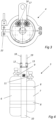
- THE figures 1 to 4 represent an avalanche triggering system 2 comprising a portable unit 3 configured to be carried by an operator and an explosion unit 4 configured to be launched by the operator.
- the portable unit 3 includes a gas storage device 5 configured to store an oxidizing gas and a combustible gas.
- the gas storage device more particularly comprises an oxidizing gas tank 6, such as an oxidizing gas bottle, and a fuel gas tank 7, such as a fuel gas bottle.
- the fuel gas tank 6 and the oxidizing gas tank 7 are removable so as to allow their replacement when they are empty.
- the portable unit 3 may for example comprise one or more fixing straps 8 making it possible to removably fix the combustible gas tank 6 and the oxidizing gas tank 7 on a support body 10 of the portable unit 3.
- the oxidizing gas contained in the oxidizing gas tank 7 can for example be dioxygen, ozone, hydrogen peroxide, halogens, or any other oxidizing gas
- the combustible gas contained in the combustible gas tank 6 can for example be dihydrogen, methane, ethane, propane, butane, pentane, acetylene, or any other combustible gas.
- the portable unit 3 further comprises a fuel gas distribution circuit 9 which is fluidly connected to the fuel gas tank 6, and a circuit oxidizing gas distribution circuit 11 which is fluidly connected to the oxidizing gas tank 7.
- the combustible gas distribution circuit 9 successively comprises a first regulator, a first solenoid valve and a first non-return valve
- the combustion circuit distribution of oxidant gas 11 successively comprises a second regulator, a second solenoid valve and a non-return valve.
- the portable unit 3 also comprises a first connection fitting 12 which is fluidly connected to the combustible gas distribution circuit 9, and a second connection fitting 13 which is fluidly connected to the oxidant gas distribution circuit 7.
- the explosion unit 4 comprises a support part 14 equipped with a gripping handle 15.
- the support part 14 comprises a primary connection fitting 16 and a secondary connection fitting 17, and the triggering system avalanches comprises a fuel gas supply conduit 18 which extends between the portable unit 3 and the explosion unit 4 and which fluidly connects the first connection connector 12 to the primary connection connector 16, and a conduit the oxidant gas supply 19 which extends between the portable unit 3 and the explosion unit 4 and which fluidly connects the second connection fitting 13 to the secondary connection fitting 17.
- the explosion unit 4 further comprises a removable cartridge 21 which is removably mounted on the support part 14, for example using a fixing collar 22.
- the removable cartridge 21 comprises in particular a casing of cartridge 23 and a removable protective cover 24 which delimit a receiving housing 25.
- the explosion unit 4 further comprises a flexible envelope 26 which is housed in the receiving housing 25 and which is configured to be at least partially filled with an explosive gas mixture formed by combustible gas and oxidant gas coming respectively from the fuel gas tank 6 and the oxidant gas tank 7.
- the flexible envelope 26 comprises an envelope chamber 27 configured to contain the explosive gas mixture, and a filling opening 28 opening into the envelope chamber 27.
- the flexible envelope 26 is more particularly deformable between a rest configuration (see figure 2 ) in which the flexible envelope 26 has a first internal volume and an inflated configuration (see the figure 1 ) in which the flexible envelope 26 has a second internal volume which is greater than the first internal volume and is less partially filled with the gas mixture explosive.
- the removable protective cover 24 is configured to be ejected from the cartridge housing 23 by the flexible envelope 26 when the flexible envelope 26 is deformed in the inflated configuration, and the flexible envelope 26 is configured to extend at least partly outside the receiving housing 25 when the flexible envelope 26 is in the inflated configuration.
- the flexible envelope 26 can for example be made of kraft paper and be folded like an accordion when it is in the rest configuration. According to another embodiment of the invention, the flexible envelope 26 can for example be made of flexible plastic material and be formed by an inflatable balloon.
- the removable cartridge 21 further comprises a dust storage part 29 which delimits an internal housing 31 containing combustible dust 32.
- the combustible dust 32 may for example include dust of agricultural origin, such as starch dust, peanut dust, wood dust, cellulose dust, flour, cornstarch and sugar dust.
- the combustible dusts 32 may also, for example, include metal dusts, such as aluminum or magnesium dusts, or chemical dusts, such as acetylsalicylic acid dusts, ascorbic acid dusts and 2.6 dusts. -Di-tert-butylphenol.
- the combustible dusts 32 may also include mineral dusts, such as coal dusts or talc, or plastic or rubber dusts, such as polyacrylonitrile dusts, polycarbonate dusts, polyester dusts, polyethylene dusts. , polypropylene dust, polystyrene dust and polyurethane dust.
- mineral dusts such as coal dusts or talc
- plastic or rubber dusts such as polyacrylonitrile dusts, polycarbonate dusts, polyester dusts, polyethylene dusts. , polypropylene dust, polystyrene dust and polyurethane dust.
- the dust storage part 29 comprises a first tubular end portion 33 which is closed by a frangible separation wall 34 and which is at least partially inserted in the flexible envelope 26, and a second tubular end portion 35 which is opposite the first tubular end portion 33 and which is closed by a frangible closing wall 36.
- the frangible separation wall 34 is configured to separate the receiving housing 25 and the internal housing 31, and more particularly to fluidly isolate the internal housing 31 from the envelope chamber 27 of the flexible envelope 26.
- the frangible separation wall 34 is formed by a frangible separation membrane
- the wall frangible shutter 36 is formed by a frangible shutter membrane.
- the support part 14 comprises a bore 37 in which the second tubular end portion 35 is removably mounted, and the second tubular end portion 35, the closing wall frangible 36 and the support part 14 delimit an internal chamber 38.
- the explosion unit 4 advantageously comprises a fuel gas supply circuit 39 which opens into the internal chamber 38 and which is fluidly connected to the fuel gas supply 18 via the primary connection connection 16, and an oxidizing gas supply circuit 41 which opens into the internal chamber 38 and which is fluidly connected to the oxidizing gas supply conduit 19 via the secondary connection connection 17.
- the frangible sealing wall 36 is configured to be ruptured when the gas pressure in the internal chamber 38 exceeds a predetermined pressure
- the frangible separation wall 34 is configured to be ruptured when the gas pressure in the internal housing 31 exceeds a predetermined pressure value.
- the explosion unit 4 is supplied with oxidant gas and combustible gas coming from the gas storage device 5
- the gas pressure in the internal chamber 38 rises to the point of causing the wall to rupture.
- frangible shutter 36 then the gas pressure in the internal housing 31 rises to the point of causing the breakage of the frangible separation wall 34, which results in the projection of combustible dust 32 into the flexible envelope 26 and allows filling the flexible envelope 26 with the explosive gas mixture.
- the explosion unit 4 further comprises a firing device 42 which is fixed to the support part 14 and which is configured to trigger the explosion of the explosive gas mixture contained in the flexible envelope 26.
- the ignition device 42 comprises a spark plug 43 which is configured to generate a spark capable of causing ignition of the explosive gas mixture.
- the spark plug 43 could be replaced by any other ignition device making it possible to cause the explosive gas mixture to ignite.
- the avalanche triggering system 2 further comprises a control unit 44 which is configured to remotely control the ignition device 42, and in particular to control the generation of a spark when the ignition device includes the spark plug 43.
- the control unit 44 is also configured to control the opening and closing of the first and second solenoid valves belonging to the fuel gas distribution circuit 9 and the oxidant gas distribution circuit 11.
- control unit 44 is carried by the portable unit 3, and comprises a microprocessor capable of developing control instructions.
- the portable unit 3 comprises a control console 45 equipped with a plurality of control buttons.
- the avalanche triggering system 2 also includes a safety device comprising a transmitter 46 which is carried by the explosion unit 4, and a receiver 47 which is carried by the portable unit 3 and which is configured to communicate with the transmitter46.
- the security device further comprises a processing unit 48 which is for example carried by the portable unit 3 and which is configured to calculate the separation distance separating the transmitter 46 from the receiver 47.
- the processing unit 48 is more particularly configured to prevent firing of the firing device 42 if the separation distance is less than the predetermined distance.
- the safety device can for example be an avalanche victim search device, also called an avalanche victim detector (AVD).
- the control unit 44 and the processing unit 48 can be formed by the same microprocessor.
- the avalanche triggering system 2 further comprises an electrical energy storage device 49, such as a rechargeable battery, which is disposed in the portable unit 3 and which is configured to electrically power the portable unit 49 and the firing device 42.
- the avalanche triggering system 2 also includes an electrical power cable 51 which electrically connects the firing device 42 to the portable unit 3.
- the avalanche triggering system 2 comprises a connecting cable which extends between the portable unit 3 and the explosion unit 4 and which contains the fuel gas supply conduit 18, the conduit oxidizing gas supply 19 and the electrical power cable 51.
- the operator activates a control button on the control console 45 so that the control unit 44 controls the firing device 42 to trigger the explosion of the explosive gas mixture.
- the shock wave generated by the explosion is transmitted to the snow cover, and makes it possible to loosen the snow and trigger a preventive avalanche.
- the explosion unit 4 could be configured to be connected to a drone and to be transported by such a drone.
- the explosion unit 4 could be provided, instead of the gripping handle 15 or in addition to the gripping handle 15, with a fixing element provided on the support part 14 and configured to removably attach the support portion 14 to the drone.
- an operator wishes to trigger a preventive avalanche using such an avalanche triggering system 2
- he attaches the explosion unit 4 to the drone and orders the drone to move to the location.
- he activates a control button of the control console 45 so that the control unit 44 controls the opening, for a predetermined duration, of the first and second solenoid valves of the distribution circuit of combustible gas 9 and of the oxidant gas distribution circuit 11, so as to fill the flexible envelope 26 with an explosive gas mixture.
- the operator activates a control button on the control console 45 so that the control unit 44 controls the firing device 42 to trigger the explosion of the explosive gas mixture.
- the operator could also order the filling of the flexible envelope 26 with an explosive gas mixture before attaching the explosion unit 4 to the drone and ordering a movement of the drone to the precise location where he wants trigger the avalanche.
Landscapes
- Engineering & Computer Science (AREA)
- General Engineering & Computer Science (AREA)
- Architecture (AREA)
- Civil Engineering (AREA)
- Structural Engineering (AREA)
- Air Bags (AREA)
- Toys (AREA)
- Filling Or Discharging Of Gas Storage Vessels (AREA)
- Portable Nailing Machines And Staplers (AREA)
- Feeding, Discharge, Calcimining, Fusing, And Gas-Generation Devices (AREA)
Claims (14)
- Lawinenauslösesystem (2), das Folgendes umfasst:- eine tragbare Einheit (3), die so ausgebildet ist, dass sie von einem Bediener getragen werden kann, wobei die tragbare Einheit (3) eine Gasspeichervorrichtung (5) umfasst, die so ausgebildet ist, dass sie ein oxidierendes Gas und ein brennbares Gas speichert,- eine Explosionseinheit (4), die so ausgebildet ist, dass durch den Bediener gestartet wird, und die mit der tragbaren Einheit (3) fluidisch verbunden ist, wobei die Explosionseinheit (4) eine flexible Hülle (26) umfasst, die so ausgebildet ist, dass sie mindestens teilweise mit einem explosiven Gasgemisch, das aus dem brennbaren Gas und dem oxidierenden Gas besteht, das aus der Gasspeichervorrichtung (5) stammt, gefüllt wird, wobei die flexible Hülle (26) zwischen einer Ruhekonfiguration, in der die flexible Hülle (26) ein erstes Innenvolumen umfasst, und einer expandierten Konfiguration, in der die flexible Hülle (26) ein zweites Innenvolumen umfasst, das größer als das erste Innenvolumen und mindestens teilweise mit dem explosiven Gasgemisch gefüllt ist, verformbar ist, wobei die Explosionseinheit (4) ferner eine Zündvorrichtung (42) umfasst, die so ausgebildet ist, dass sie die Explosion des in der flexiblen Hülle (26) enthaltenen explosiven Gasgemisches auslöst, und- eine Steuereinheit (44), die so ausgebildet ist, dass sie die Zündvorrichtung (42) von der Ferne aus steuert.
- Lawinenauslösesystem (2) nach Anspruch 1, wobei die Gasspeichervorrichtung (5) einen Brenngastank (6) und einen Oxidationsgastank (7) umfasst.
- Lawinenauslösesystem (2) nach Anspruch 2, wobei der Brenngastank (6) und der Oxidationsgastank (7) entfernbar sind.
- Lawinenauslösesystem (2) nach Anspruch 2 oder 3, wobei die tragbare Einheit (3) einen Brenngasverteilungskreislauf (9), der mit dem Brenngastank (6) fluidisch verbunden ist, und einen Oxidationsgasverteilungskreislauf (11), der mit dem Oxidationsgastank (7) fluidisch verbunden ist, umfasst.
- Lawinenauslösesystem (2) nach Anspruch 4, das eine Brenngas-Zufuhrleitung (18), die sich zwischen der tragbaren Einheit (3) und der Explosionseinheit (4) erstreckt und die so ausgebildet ist, dass sie den Brenngasverteilungskreislauf (9) fluidisch mit der flexiblen Hülle (26) verbindet, und eine Oxidationsgas-Zufuhrleitung (19) umfasst, die sich zwischen der tragbaren Einheit (3) und der Explosionseinheit (4) erstreckt und die so ausgebildet ist, dass sie den Oxidationsgas-Verteilungskreislauf (11) mit der flexiblen Hülle (26) fluidisch verbindet.
- Lawinenauslösesystem (2) nach einem der Ansprüche 1 bis 5, das ferner eine Sicherheitsvorrichtung umfasst, die so ausgebildet ist, dass sie ein Zünden der Zündvorrichtung (42) verhindert, wenn ein Trennungsabstand, der die Explosionseinheit (3) und die tragbare Einheit (4) trennt, kleiner ist als ein vorbestimmter Wert.
- Lawinenauslösesystem (2) nach Anspruch 6, wobei die Sicherheitsvorrichtung einen Sender (46), der von einer der tragbaren Einheit (3) und der Explosionseinheit (4) getragen wird, einen Empfänger (47) umfasst, der von der anderen der tragbaren Einheit (3) und der Explosionseinheit (4) getragen wird und der so ausgebildet ist, dass er mit dem Sender (46) kommuniziert, wobei die Sicherheitsvorrichtung so ausgebildet ist, dass sie den Trennungsabstand, der den Sender (46) und den Empfänger (47) trennt, berechnet und sie das Zünden der Zündvorrichtung verhindert, wenn der Trennungsabstand kleiner ist als der vorbestimmte Abstand.
- Lawinenauslösesystem (2) nach einem der Ansprüche 1 bis 7, wobei die Explosionseinheit (4) brennbaren Staub (32) umfasst, der so ausgebildet ist, dass er in der flexiblen Hülle (26) enthalten ist.
- Lawinenauslösesystem (2) nach Anspruch 8, wobei die Explosionseinheit (4) ein Innengehäuse (31) umfasst, in dem der brennbare Staub (32) enthalten ist, wobei die Explosionseinheit (4) so ausgebildet ist, dass der brennbare Staub (32) durch das oxidierende Gas und das brennbare Gas, die aus der Gasspeichervorrichtung (5) stammen, in die flexible Hülle (26) geschleudert wird, wenn die flexible Hülle (26) mindestens teilweise mit dem explosiven Gasgemisch gefüllt ist.
- Lawinenauslösesystem (2) nach einem der Ansprüche 1 bis 9, wobei die Explosionseinheit (4) eine entfernbare Patrone (21) umfasst, die ein Aufnahmegehäuse (25) umfasst, in dem die flexible Hülle (26) untergebracht ist.
- Lawinenauslösesystem (2) nach Anspruch 10, wobei die entfernbare Patrone (21) ein Patronengehäuse (23) und eine entfernbare Schutzabdeckung (24) umfasst, die das Aufnahmegehäuse (25) mindestens teilweise begrenzen, wobei die entfernbare Schutzabdeckung (24) so ausgebildet ist, dass sie durch die flexible Hülle (26) aus dem Patronengehäuse (23) ausgeworfen wird, wenn die flexible Hülle (26) in die expandierte Konfiguration verformt wird.
- Lawinenauslösesystem (2) nach einem der Ansprüche 1 bis 11, wobei die Steuereinheit (44) von der tragbaren Einheit (3) getragen wird.
- Lawinenauslösesystem (2) nach einem der Ansprüche 1 bis 12, wobei die tragbare Einheit (3) eine elektrische Energiespeichervorrichtung (49) umfasst, die so ausgebildet ist, dass sie die tragbare Einheit (3) und die Zündvorrichtung (42) mit Strom versorgt.
- Lawinenauslösesystem (2) nach einem der Ansprüche 1 bis 13, das ein Stromkabel (51) umfasst, das die Zündvorrichtung (42) elektrisch mit der tragbaren Einheit (3) verbindet.
Priority Applications (1)
| Application Number | Priority Date | Filing Date | Title |
|---|---|---|---|
| SI202030445T SI4042097T1 (sl) | 2019-10-10 | 2020-10-08 | Sprožilni sistem za sprožitve plazov |
Applications Claiming Priority (2)
| Application Number | Priority Date | Filing Date | Title |
|---|---|---|---|
| FR1911258A FR3101940B1 (fr) | 2019-10-10 | 2019-10-10 | Système de déclenchement d’avalanches |
| PCT/FR2020/051772 WO2021069839A1 (fr) | 2019-10-10 | 2020-10-08 | Système de déclenchement d'avalanches |
Publications (3)
| Publication Number | Publication Date |
|---|---|
| EP4042097A1 EP4042097A1 (de) | 2022-08-17 |
| EP4042097B1 true EP4042097B1 (de) | 2024-03-06 |
| EP4042097B8 EP4042097B8 (de) | 2024-12-25 |
Family
ID=69810931
Family Applications (1)
| Application Number | Title | Priority Date | Filing Date |
|---|---|---|---|
| EP20793766.5A Active EP4042097B8 (de) | 2019-10-10 | 2020-10-08 | Lawinenauslösesystem |
Country Status (9)
| Country | Link |
|---|---|
| US (1) | US12078466B2 (de) |
| EP (1) | EP4042097B8 (de) |
| JP (1) | JP7618351B2 (de) |
| CA (1) | CA3153939A1 (de) |
| CL (1) | CL2022000897A1 (de) |
| ES (1) | ES2980402T3 (de) |
| FR (1) | FR3101940B1 (de) |
| SI (1) | SI4042097T1 (de) |
| WO (1) | WO2021069839A1 (de) |
Families Citing this family (1)
| Publication number | Priority date | Publication date | Assignee | Title |
|---|---|---|---|---|
| US12332039B1 (en) | 2024-02-17 | 2025-06-17 | Alpine Snowpack Management LLC | Avalanche triggering apparatus |
Family Cites Families (19)
| Publication number | Priority date | Publication date | Assignee | Title |
|---|---|---|---|---|
| JPS6139300U (ja) * | 1984-08-10 | 1986-03-12 | 三菱電機株式会社 | 起爆装置 |
| GB2199289A (en) | 1986-12-30 | 1988-07-06 | Nash Frazer Ltd | Minefield clearing systems |
| US4873928A (en) * | 1987-06-15 | 1989-10-17 | Apti, Inc. | Nuclear-sized explosions without radiation |
| AR245818A1 (es) * | 1988-03-03 | 1994-02-28 | Schippers Jacob | Dispositivo para desencadenar un alud. |
| FR2636729B1 (fr) | 1988-09-19 | 1990-12-07 | Schippers Jacob | Procede et dispositif pour declencher une avalanche |
| JP3481082B2 (ja) * | 1996-06-27 | 2003-12-22 | ユニバーサル造船株式会社 | 遠隔爆破方法および遠隔爆破装置 |
| RU2107889C1 (ru) | 1996-08-08 | 1998-03-27 | Российский федеральный ядерный центр - Всероссийский научно-исследовательский институт технической физики | Способ обрушения сооружений и устройство для его реализации |
| FR2765320B1 (fr) * | 1997-06-26 | 1999-09-17 | Jacob Schippers | Dispositif pour provoquer la rupture d'une corniche de neige |
| FR2771168B1 (fr) | 1997-11-17 | 1999-12-10 | Commissariat Energie Atomique | Procede de declenchement artificiel d'une avalanche et dispositif pour la mise en oeuvre de ce procede |
| FR2811420B1 (fr) * | 2000-07-05 | 2003-01-17 | Giat Ind Sa | Projectile pour le declenchement d'avalanches |
| RU2284389C2 (ru) | 2004-10-26 | 2006-09-27 | Общество с ограниченной ответственностью Научно-технический центр "Системы пожарной безопасности" | Способ инициирования схода лавины и устройство для его осуществления |
| US7707938B2 (en) * | 2005-05-16 | 2010-05-04 | Hisel Stanley D | Apparatus and method for avalanche control |
| FR2897931B1 (fr) * | 2006-02-24 | 2008-05-09 | Technologie Alpine De Securite | Dispositif de declenchement d'avalanche |
| WO2009049345A1 (de) * | 2007-10-19 | 2009-04-23 | Markus Stracke | Vorrichtung zum auslösen von lawinen |
| FR2925152B1 (fr) * | 2007-12-14 | 2013-06-28 | Technologie Alpine De Securite T A S | Dispositif de declenchement d'avalanches |
| FR2953922B1 (fr) * | 2009-12-10 | 2011-12-09 | Technologie Alpine De Securite Tas | Dispositif de declenchement d'avalanches |
| FR2958739B1 (fr) * | 2010-04-09 | 2012-05-11 | Technologie Alpine De Securite Tas | Dispositif de declenchement d'avalanche |
| FR2964732B1 (fr) * | 2010-09-14 | 2013-06-14 | Alp Artifices | Projectile pour declenchement d'avalanche |
| US10968579B2 (en) * | 2018-07-26 | 2021-04-06 | Avy Blasters, LLC | Avalanche control device |
-
2019
- 2019-10-10 FR FR1911258A patent/FR3101940B1/fr not_active Expired - Fee Related
-
2020
- 2020-10-08 JP JP2022521719A patent/JP7618351B2/ja active Active
- 2020-10-08 ES ES20793766T patent/ES2980402T3/es active Active
- 2020-10-08 US US17/767,780 patent/US12078466B2/en active Active
- 2020-10-08 CA CA3153939A patent/CA3153939A1/fr active Pending
- 2020-10-08 WO PCT/FR2020/051772 patent/WO2021069839A1/fr not_active Ceased
- 2020-10-08 SI SI202030445T patent/SI4042097T1/sl unknown
- 2020-10-08 EP EP20793766.5A patent/EP4042097B8/de active Active
-
2022
- 2022-04-07 CL CL2022000897A patent/CL2022000897A1/es unknown
Also Published As
| Publication number | Publication date |
|---|---|
| CA3153939A1 (fr) | 2021-04-15 |
| ES2980402T3 (es) | 2024-10-01 |
| WO2021069839A1 (fr) | 2021-04-15 |
| EP4042097A1 (de) | 2022-08-17 |
| EP4042097B8 (de) | 2024-12-25 |
| US12078466B2 (en) | 2024-09-03 |
| US20240085163A1 (en) | 2024-03-14 |
| FR3101940A1 (fr) | 2021-04-16 |
| JP7618351B2 (ja) | 2025-01-21 |
| CL2022000897A1 (es) | 2023-01-13 |
| SI4042097T1 (sl) | 2024-07-31 |
| FR3101940B1 (fr) | 2021-10-15 |
| JP2022553916A (ja) | 2022-12-27 |
Similar Documents
| Publication | Publication Date | Title |
|---|---|---|
| NO163652B (no) | Anordning for frembringelse av en narremaalsky, saerlig medinfraroed utstraaling. | |
| CA2432050C (en) | Infra-red emitting decoy flare | |
| EP4042097B1 (de) | Lawinenauslösesystem | |
| EP2220454A2 (de) | Lawinenauslösesystem | |
| WO2020236848A1 (en) | Explosive detonating system and components | |
| EP0991912B1 (de) | Vorrichtung zur auslösung einer lawine | |
| EP0991911B1 (de) | Vorrichtung die das einstürzen einer schneeplatte einleitet | |
| EP1205727B1 (de) | Pyrotechnischer Verzögerungszünder | |
| EP0109161B1 (de) | Hülle für Sprengpatrone | |
| RU2820622C1 (ru) | Система инициирования лавины | |
| FR2811420A1 (fr) | Projectile pour le declenchement d'avalanches | |
| FR2559069A1 (fr) | Dispositif et procede de securite contre les incendies et les explosions pour le stockage des matieres combustibles ou explosives | |
| EP1530020B1 (de) | Zündvorrichtung für mindestens zwei pyrotechnische Zusammensetzungen oder antreibende Ladungen eines Projektiles | |
| EP4263348B1 (de) | Vorrichtung zur erzeugung einer stosswelle | |
| FR2758879A1 (fr) | Dispositif de lancement de grenade lacrymogene | |
| FR2988389A1 (fr) | Composition deflagrante pour le declanchement d'avalanche et procede de declenchement d'avalanche | |
| EP0943887A1 (de) | Bausatz zum Umrüsten eines Sprenggeschosses auf ein Bentonstrukturen brechendes Geschoss, sowie ein derart umgerüstetes Geschoss | |
| FR2912922A1 (fr) | Dispositif d'extinction des incendies | |
| WO2003040645A1 (fr) | Engin explosif a plusieurs elements unitaires | |
| FR2469690A1 (fr) | Vehicule pour signal de detresse avec eclairant et leurres electromagnetiques | |
| FR2981146A1 (fr) | Dispositif d'allumage. | |
| CH359383A (fr) | Mine | |
| FR2507763A1 (fr) | Perfectionnements apportes aux systemes d'armes tels que lance-roquette antichar | |
| BE487209A (de) |
Legal Events
| Date | Code | Title | Description |
|---|---|---|---|
| STAA | Information on the status of an ep patent application or granted ep patent |
Free format text: STATUS: UNKNOWN |
|
| STAA | Information on the status of an ep patent application or granted ep patent |
Free format text: STATUS: THE INTERNATIONAL PUBLICATION HAS BEEN MADE |
|
| PUAI | Public reference made under article 153(3) epc to a published international application that has entered the european phase |
Free format text: ORIGINAL CODE: 0009012 |
|
| STAA | Information on the status of an ep patent application or granted ep patent |
Free format text: STATUS: REQUEST FOR EXAMINATION WAS MADE |
|
| 17P | Request for examination filed |
Effective date: 20220428 |
|
| AK | Designated contracting states |
Kind code of ref document: A1 Designated state(s): AL AT BE BG CH CY CZ DE DK EE ES FI FR GB GR HR HU IE IS IT LI LT LU LV MC MK MT NL NO PL PT RO RS SE SI SK SM TR |
|
| DAV | Request for validation of the european patent (deleted) | ||
| DAX | Request for extension of the european patent (deleted) | ||
| GRAP | Despatch of communication of intention to grant a patent |
Free format text: ORIGINAL CODE: EPIDOSNIGR1 |
|
| STAA | Information on the status of an ep patent application or granted ep patent |
Free format text: STATUS: GRANT OF PATENT IS INTENDED |
|
| INTG | Intention to grant announced |
Effective date: 20230508 |
|
| GRAS | Grant fee paid |
Free format text: ORIGINAL CODE: EPIDOSNIGR3 |
|
| GRAA | (expected) grant |
Free format text: ORIGINAL CODE: 0009210 |
|
| STAA | Information on the status of an ep patent application or granted ep patent |
Free format text: STATUS: THE PATENT HAS BEEN GRANTED |
|
| AK | Designated contracting states |
Kind code of ref document: B1 Designated state(s): AL AT BE BG CH CY CZ DE DK EE ES FI FR GB GR HR HU IE IS IT LI LT LU LV MC MK MT NL NO PL PT RO RS SE SI SK SM TR |
|
| REG | Reference to a national code |
Ref country code: CH Ref legal event code: EP |
|
| REG | Reference to a national code |
Ref country code: IE Ref legal event code: FG4D Free format text: LANGUAGE OF EP DOCUMENT: FRENCH |
|
| REG | Reference to a national code |
Ref country code: DE Ref legal event code: R096 Ref document number: 602020026918 Country of ref document: DE |
|
| REG | Reference to a national code |
Ref country code: SE Ref legal event code: TRGR Ref country code: LT Ref legal event code: MG9D |
|
| PG25 | Lapsed in a contracting state [announced via postgrant information from national office to epo] |
Ref country code: LT Free format text: LAPSE BECAUSE OF FAILURE TO SUBMIT A TRANSLATION OF THE DESCRIPTION OR TO PAY THE FEE WITHIN THE PRESCRIBED TIME-LIMIT Effective date: 20240306 |
|
| REG | Reference to a national code |
Ref country code: NL Ref legal event code: MP Effective date: 20240306 |
|
| PG25 | Lapsed in a contracting state [announced via postgrant information from national office to epo] |
Ref country code: GR Free format text: LAPSE BECAUSE OF FAILURE TO SUBMIT A TRANSLATION OF THE DESCRIPTION OR TO PAY THE FEE WITHIN THE PRESCRIBED TIME-LIMIT Effective date: 20240607 |
|
| PG25 | Lapsed in a contracting state [announced via postgrant information from national office to epo] |
Ref country code: HR Free format text: LAPSE BECAUSE OF FAILURE TO SUBMIT A TRANSLATION OF THE DESCRIPTION OR TO PAY THE FEE WITHIN THE PRESCRIBED TIME-LIMIT Effective date: 20240306 Ref country code: RS Free format text: LAPSE BECAUSE OF FAILURE TO SUBMIT A TRANSLATION OF THE DESCRIPTION OR TO PAY THE FEE WITHIN THE PRESCRIBED TIME-LIMIT Effective date: 20240606 |
|
| PG25 | Lapsed in a contracting state [announced via postgrant information from national office to epo] |
Ref country code: RS Free format text: LAPSE BECAUSE OF FAILURE TO SUBMIT A TRANSLATION OF THE DESCRIPTION OR TO PAY THE FEE WITHIN THE PRESCRIBED TIME-LIMIT Effective date: 20240606 Ref country code: LT Free format text: LAPSE BECAUSE OF FAILURE TO SUBMIT A TRANSLATION OF THE DESCRIPTION OR TO PAY THE FEE WITHIN THE PRESCRIBED TIME-LIMIT Effective date: 20240306 Ref country code: HR Free format text: LAPSE BECAUSE OF FAILURE TO SUBMIT A TRANSLATION OF THE DESCRIPTION OR TO PAY THE FEE WITHIN THE PRESCRIBED TIME-LIMIT Effective date: 20240306 Ref country code: GR Free format text: LAPSE BECAUSE OF FAILURE TO SUBMIT A TRANSLATION OF THE DESCRIPTION OR TO PAY THE FEE WITHIN THE PRESCRIBED TIME-LIMIT Effective date: 20240607 Ref country code: FI Free format text: LAPSE BECAUSE OF FAILURE TO SUBMIT A TRANSLATION OF THE DESCRIPTION OR TO PAY THE FEE WITHIN THE PRESCRIBED TIME-LIMIT Effective date: 20240306 Ref country code: BG Free format text: LAPSE BECAUSE OF FAILURE TO SUBMIT A TRANSLATION OF THE DESCRIPTION OR TO PAY THE FEE WITHIN THE PRESCRIBED TIME-LIMIT Effective date: 20240306 |
|
| PG25 | Lapsed in a contracting state [announced via postgrant information from national office to epo] |
Ref country code: LV Free format text: LAPSE BECAUSE OF FAILURE TO SUBMIT A TRANSLATION OF THE DESCRIPTION OR TO PAY THE FEE WITHIN THE PRESCRIBED TIME-LIMIT Effective date: 20240306 |
|
| PG25 | Lapsed in a contracting state [announced via postgrant information from national office to epo] |
Ref country code: NL Free format text: LAPSE BECAUSE OF FAILURE TO SUBMIT A TRANSLATION OF THE DESCRIPTION OR TO PAY THE FEE WITHIN THE PRESCRIBED TIME-LIMIT Effective date: 20240306 |
|
| PG25 | Lapsed in a contracting state [announced via postgrant information from national office to epo] |
Ref country code: NL Free format text: LAPSE BECAUSE OF FAILURE TO SUBMIT A TRANSLATION OF THE DESCRIPTION OR TO PAY THE FEE WITHIN THE PRESCRIBED TIME-LIMIT Effective date: 20240306 |
|
| REG | Reference to a national code |
Ref country code: CH Ref legal event code: PK Free format text: RECTIFICATIONS |
|
| REG | Reference to a national code |
Ref country code: ES Ref legal event code: FG2A Ref document number: 2980402 Country of ref document: ES Kind code of ref document: T3 Effective date: 20241001 |
|
| PG25 | Lapsed in a contracting state [announced via postgrant information from national office to epo] |
Ref country code: IS Free format text: LAPSE BECAUSE OF FAILURE TO SUBMIT A TRANSLATION OF THE DESCRIPTION OR TO PAY THE FEE WITHIN THE PRESCRIBED TIME-LIMIT Effective date: 20240706 |
|
| PG25 | Lapsed in a contracting state [announced via postgrant information from national office to epo] |
Ref country code: SM Free format text: LAPSE BECAUSE OF FAILURE TO SUBMIT A TRANSLATION OF THE DESCRIPTION OR TO PAY THE FEE WITHIN THE PRESCRIBED TIME-LIMIT Effective date: 20240306 Ref country code: PT Free format text: LAPSE BECAUSE OF FAILURE TO SUBMIT A TRANSLATION OF THE DESCRIPTION OR TO PAY THE FEE WITHIN THE PRESCRIBED TIME-LIMIT Effective date: 20240708 |
|
| PG25 | Lapsed in a contracting state [announced via postgrant information from national office to epo] |
Ref country code: EE Free format text: LAPSE BECAUSE OF FAILURE TO SUBMIT A TRANSLATION OF THE DESCRIPTION OR TO PAY THE FEE WITHIN THE PRESCRIBED TIME-LIMIT Effective date: 20240306 Ref country code: CZ Free format text: LAPSE BECAUSE OF FAILURE TO SUBMIT A TRANSLATION OF THE DESCRIPTION OR TO PAY THE FEE WITHIN THE PRESCRIBED TIME-LIMIT Effective date: 20240306 |
|
| RIN2 | Information on inventor provided after grant (corrected) |
Inventor name: BOUILLANE, OLIVIER Inventor name: COSTECALDE, VINCENT Inventor name: VILLALONGA, FRANCOIS-XAVIER Inventor name: FLEUR, PIERRE Inventor name: NOEL, LOUIS Inventor name: NEUVILLE, JEAN-MARC Inventor name: CONSTANT, STEPHANE Inventor name: RIVOAL, OLIVIER |
|
| PG25 | Lapsed in a contracting state [announced via postgrant information from national office to epo] |
Ref country code: PL Free format text: LAPSE BECAUSE OF FAILURE TO SUBMIT A TRANSLATION OF THE DESCRIPTION OR TO PAY THE FEE WITHIN THE PRESCRIBED TIME-LIMIT Effective date: 20240306 |
|
| PG25 | Lapsed in a contracting state [announced via postgrant information from national office to epo] |
Ref country code: SK Free format text: LAPSE BECAUSE OF FAILURE TO SUBMIT A TRANSLATION OF THE DESCRIPTION OR TO PAY THE FEE WITHIN THE PRESCRIBED TIME-LIMIT Effective date: 20240306 |
|
| PG25 | Lapsed in a contracting state [announced via postgrant information from national office to epo] |
Ref country code: SM Free format text: LAPSE BECAUSE OF FAILURE TO SUBMIT A TRANSLATION OF THE DESCRIPTION OR TO PAY THE FEE WITHIN THE PRESCRIBED TIME-LIMIT Effective date: 20240306 Ref country code: SK Free format text: LAPSE BECAUSE OF FAILURE TO SUBMIT A TRANSLATION OF THE DESCRIPTION OR TO PAY THE FEE WITHIN THE PRESCRIBED TIME-LIMIT Effective date: 20240306 Ref country code: RO Free format text: LAPSE BECAUSE OF FAILURE TO SUBMIT A TRANSLATION OF THE DESCRIPTION OR TO PAY THE FEE WITHIN THE PRESCRIBED TIME-LIMIT Effective date: 20240306 Ref country code: PT Free format text: LAPSE BECAUSE OF FAILURE TO SUBMIT A TRANSLATION OF THE DESCRIPTION OR TO PAY THE FEE WITHIN THE PRESCRIBED TIME-LIMIT Effective date: 20240708 Ref country code: PL Free format text: LAPSE BECAUSE OF FAILURE TO SUBMIT A TRANSLATION OF THE DESCRIPTION OR TO PAY THE FEE WITHIN THE PRESCRIBED TIME-LIMIT Effective date: 20240306 Ref country code: IS Free format text: LAPSE BECAUSE OF FAILURE TO SUBMIT A TRANSLATION OF THE DESCRIPTION OR TO PAY THE FEE WITHIN THE PRESCRIBED TIME-LIMIT Effective date: 20240706 Ref country code: EE Free format text: LAPSE BECAUSE OF FAILURE TO SUBMIT A TRANSLATION OF THE DESCRIPTION OR TO PAY THE FEE WITHIN THE PRESCRIBED TIME-LIMIT Effective date: 20240306 Ref country code: CZ Free format text: LAPSE BECAUSE OF FAILURE TO SUBMIT A TRANSLATION OF THE DESCRIPTION OR TO PAY THE FEE WITHIN THE PRESCRIBED TIME-LIMIT Effective date: 20240306 |
|
| GRAT | Correction requested after decision to grant or after decision to maintain patent in amended form |
Free format text: ORIGINAL CODE: EPIDOSNCDEC |
|
| REG | Reference to a national code |
Ref country code: CH Ref legal event code: PK Free format text: RECTIFICATIONS Ref country code: CH Ref legal event code: PK Free format text: RECTIFICATION B8 |
|
| REG | Reference to a national code |
Ref country code: DE Ref legal event code: R097 Ref document number: 602020026918 Country of ref document: DE |
|
| RIN2 | Information on inventor provided after grant (corrected) |
Inventor name: BOUILLANNE, OLIVIER Inventor name: COSTECALDE, VINCENT Inventor name: VILLALONGA, FRANCOIS-XAVIER Inventor name: FLEUR, PIERRE Inventor name: NOEL, LOUIS Inventor name: NEUVILLE, JEAN-MARC Inventor name: CONSTANT, STEPHANE Inventor name: RIVOAL, OLIVIER |
|
| PLBE | No opposition filed within time limit |
Free format text: ORIGINAL CODE: 0009261 |
|
| STAA | Information on the status of an ep patent application or granted ep patent |
Free format text: STATUS: NO OPPOSITION FILED WITHIN TIME LIMIT |
|
| PG25 | Lapsed in a contracting state [announced via postgrant information from national office to epo] |
Ref country code: DK Free format text: LAPSE BECAUSE OF FAILURE TO SUBMIT A TRANSLATION OF THE DESCRIPTION OR TO PAY THE FEE WITHIN THE PRESCRIBED TIME-LIMIT Effective date: 20240306 |
|
| PG25 | Lapsed in a contracting state [announced via postgrant information from national office to epo] |
Ref country code: DK Free format text: LAPSE BECAUSE OF FAILURE TO SUBMIT A TRANSLATION OF THE DESCRIPTION OR TO PAY THE FEE WITHIN THE PRESCRIBED TIME-LIMIT Effective date: 20240306 |
|
| 26N | No opposition filed |
Effective date: 20241209 |
|
| P01 | Opt-out of the competence of the unified patent court (upc) registered |
Free format text: CASE NUMBER: APP_7896/2025 Effective date: 20250217 |
|
| PGFP | Annual fee paid to national office [announced via postgrant information from national office to epo] |
Ref country code: SI Payment date: 20250407 Year of fee payment: 5 |
|
| GBPC | Gb: european patent ceased through non-payment of renewal fee |
Effective date: 20241008 |
|
| PG25 | Lapsed in a contracting state [announced via postgrant information from national office to epo] |
Ref country code: MC Free format text: LAPSE BECAUSE OF FAILURE TO SUBMIT A TRANSLATION OF THE DESCRIPTION OR TO PAY THE FEE WITHIN THE PRESCRIBED TIME-LIMIT Effective date: 20240306 |
|
| PGFP | Annual fee paid to national office [announced via postgrant information from national office to epo] |
Ref country code: DE Payment date: 20250422 Year of fee payment: 5 |
|
| PG25 | Lapsed in a contracting state [announced via postgrant information from national office to epo] |
Ref country code: GB Free format text: LAPSE BECAUSE OF NON-PAYMENT OF DUE FEES Effective date: 20241008 |
|
| PGFP | Annual fee paid to national office [announced via postgrant information from national office to epo] |
Ref country code: ES Payment date: 20250416 Year of fee payment: 5 |
|
| PGFP | Annual fee paid to national office [announced via postgrant information from national office to epo] |
Ref country code: NO Payment date: 20250422 Year of fee payment: 5 |
|
| PG25 | Lapsed in a contracting state [announced via postgrant information from national office to epo] |
Ref country code: BE Free format text: LAPSE BECAUSE OF NON-PAYMENT OF DUE FEES Effective date: 20241031 Ref country code: LU Free format text: LAPSE BECAUSE OF NON-PAYMENT OF DUE FEES Effective date: 20241008 |
|
| PGFP | Annual fee paid to national office [announced via postgrant information from national office to epo] |
Ref country code: IT Payment date: 20250417 Year of fee payment: 5 |
|
| PGFP | Annual fee paid to national office [announced via postgrant information from national office to epo] |
Ref country code: FR Payment date: 20250418 Year of fee payment: 5 |
|
| PGFP | Annual fee paid to national office [announced via postgrant information from national office to epo] |
Ref country code: CH Payment date: 20250429 Year of fee payment: 5 |
|
| PGFP | Annual fee paid to national office [announced via postgrant information from national office to epo] |
Ref country code: TR Payment date: 20250407 Year of fee payment: 5 |
|
| PGFP | Annual fee paid to national office [announced via postgrant information from national office to epo] |
Ref country code: SE Payment date: 20250415 Year of fee payment: 5 |
|
| REG | Reference to a national code |
Ref country code: BE Ref legal event code: MM Effective date: 20241031 |
|
| REG | Reference to a national code |
Ref country code: AT Ref legal event code: UEP Ref document number: 1663921 Country of ref document: AT Kind code of ref document: T Effective date: 20240306 |
|
| PG25 | Lapsed in a contracting state [announced via postgrant information from national office to epo] |
Ref country code: IE Free format text: LAPSE BECAUSE OF NON-PAYMENT OF DUE FEES Effective date: 20241008 |
|
| PGFP | Annual fee paid to national office [announced via postgrant information from national office to epo] |
Ref country code: AT Payment date: 20260113 Year of fee payment: 5 |
|
| PG25 | Lapsed in a contracting state [announced via postgrant information from national office to epo] |
Ref country code: CY Free format text: LAPSE BECAUSE OF FAILURE TO SUBMIT A TRANSLATION OF THE DESCRIPTION OR TO PAY THE FEE WITHIN THE PRESCRIBED TIME-LIMIT; INVALID AB INITIO Effective date: 20201008 |