EP4042097B1 - Avalanche triggering system - Google Patents
Avalanche triggering system Download PDFInfo
- Publication number
- EP4042097B1 EP4042097B1 EP20793766.5A EP20793766A EP4042097B1 EP 4042097 B1 EP4042097 B1 EP 4042097B1 EP 20793766 A EP20793766 A EP 20793766A EP 4042097 B1 EP4042097 B1 EP 4042097B1
- Authority
- EP
- European Patent Office
- Prior art keywords
- unit
- triggering system
- explosion
- flexible envelope
- portable unit
- Prior art date
- Legal status (The legal status is an assumption and is not a legal conclusion. Google has not performed a legal analysis and makes no representation as to the accuracy of the status listed.)
- Active
Links
- 238000004880 explosion Methods 0.000 claims description 71
- 230000001590 oxidative effect Effects 0.000 claims description 48
- 239000002360 explosive Substances 0.000 claims description 37
- 239000000428 dust Substances 0.000 claims description 33
- 239000000203 mixture Substances 0.000 claims description 32
- 238000000926 separation method Methods 0.000 claims description 24
- 230000001681 protective effect Effects 0.000 claims description 6
- 238000004146 energy storage Methods 0.000 claims description 3
- 239000007789 gas Substances 0.000 description 108
- 238000010304 firing Methods 0.000 description 16
- 239000002737 fuel gas Substances 0.000 description 16
- 239000007800 oxidant agent Substances 0.000 description 14
- OFBQJSOFQDEBGM-UHFFFAOYSA-N n-pentane Natural products CCCCC OFBQJSOFQDEBGM-UHFFFAOYSA-N 0.000 description 6
- 230000003449 preventive effect Effects 0.000 description 6
- 238000000034 method Methods 0.000 description 5
- CIWBSHSKHKDKBQ-JLAZNSOCSA-N Ascorbic acid Chemical compound OC[C@H](O)[C@H]1OC(=O)C(O)=C1O CIWBSHSKHKDKBQ-JLAZNSOCSA-N 0.000 description 4
- MHAJPDPJQMAIIY-UHFFFAOYSA-N Hydrogen peroxide Chemical compound OO MHAJPDPJQMAIIY-UHFFFAOYSA-N 0.000 description 4
- ATUOYWHBWRKTHZ-UHFFFAOYSA-N Propane Chemical compound CCC ATUOYWHBWRKTHZ-UHFFFAOYSA-N 0.000 description 4
- 208000027418 Wounds and injury Diseases 0.000 description 4
- 230000006378 damage Effects 0.000 description 4
- 208000014674 injury Diseases 0.000 description 4
- 238000009434 installation Methods 0.000 description 4
- VNWKTOKETHGBQD-UHFFFAOYSA-N methane Chemical compound C VNWKTOKETHGBQD-UHFFFAOYSA-N 0.000 description 4
- -1 polyethylene Polymers 0.000 description 4
- 239000012528 membrane Substances 0.000 description 3
- 238000007789 sealing Methods 0.000 description 3
- 230000035939 shock Effects 0.000 description 3
- 235000017060 Arachis glabrata Nutrition 0.000 description 2
- 244000105624 Arachis hypogaea Species 0.000 description 2
- 235000010777 Arachis hypogaea Nutrition 0.000 description 2
- 235000018262 Arachis monticola Nutrition 0.000 description 2
- BSYNRYMUTXBXSQ-UHFFFAOYSA-N Aspirin Chemical compound CC(=O)OC1=CC=CC=C1C(O)=O BSYNRYMUTXBXSQ-UHFFFAOYSA-N 0.000 description 2
- 229920002261 Corn starch Polymers 0.000 description 2
- MYMOFIZGZYHOMD-UHFFFAOYSA-N Dioxygen Chemical compound O=O MYMOFIZGZYHOMD-UHFFFAOYSA-N 0.000 description 2
- OTMSDBZUPAUEDD-UHFFFAOYSA-N Ethane Chemical compound CC OTMSDBZUPAUEDD-UHFFFAOYSA-N 0.000 description 2
- UFHFLCQGNIYNRP-UHFFFAOYSA-N Hydrogen Chemical compound [H][H] UFHFLCQGNIYNRP-UHFFFAOYSA-N 0.000 description 2
- FYYHWMGAXLPEAU-UHFFFAOYSA-N Magnesium Chemical compound [Mg] FYYHWMGAXLPEAU-UHFFFAOYSA-N 0.000 description 2
- CBENFWSGALASAD-UHFFFAOYSA-N Ozone Chemical compound [O-][O+]=O CBENFWSGALASAD-UHFFFAOYSA-N 0.000 description 2
- 239000004698 Polyethylene Substances 0.000 description 2
- 239000004743 Polypropylene Substances 0.000 description 2
- 239000004793 Polystyrene Substances 0.000 description 2
- 229920002472 Starch Polymers 0.000 description 2
- 229960001138 acetylsalicylic acid Drugs 0.000 description 2
- HSFWRNGVRCDJHI-UHFFFAOYSA-N alpha-acetylene Natural products C#C HSFWRNGVRCDJHI-UHFFFAOYSA-N 0.000 description 2
- 229910052782 aluminium Inorganic materials 0.000 description 2
- XAGFODPZIPBFFR-UHFFFAOYSA-N aluminium Chemical compound [Al] XAGFODPZIPBFFR-UHFFFAOYSA-N 0.000 description 2
- 229960005070 ascorbic acid Drugs 0.000 description 2
- 235000010323 ascorbic acid Nutrition 0.000 description 2
- 239000011668 ascorbic acid Substances 0.000 description 2
- 239000001273 butane Substances 0.000 description 2
- 239000001913 cellulose Substances 0.000 description 2
- 229920002678 cellulose Polymers 0.000 description 2
- 239000003245 coal Substances 0.000 description 2
- 239000008120 corn starch Substances 0.000 description 2
- 229940099112 cornstarch Drugs 0.000 description 2
- 229910001882 dioxygen Inorganic materials 0.000 description 2
- 229920001971 elastomer Polymers 0.000 description 2
- 125000002534 ethynyl group Chemical group [H]C#C* 0.000 description 2
- 235000013312 flour Nutrition 0.000 description 2
- 229910052736 halogen Inorganic materials 0.000 description 2
- 150000002367 halogens Chemical class 0.000 description 2
- 229910052500 inorganic mineral Inorganic materials 0.000 description 2
- 229910052749 magnesium Inorganic materials 0.000 description 2
- 239000011777 magnesium Substances 0.000 description 2
- 239000000463 material Substances 0.000 description 2
- 229910052751 metal Inorganic materials 0.000 description 2
- 239000002184 metal Substances 0.000 description 2
- 239000011707 mineral Substances 0.000 description 2
- IJDNQMDRQITEOD-UHFFFAOYSA-N n-butane Chemical compound CCCC IJDNQMDRQITEOD-UHFFFAOYSA-N 0.000 description 2
- 235000020232 peanut Nutrition 0.000 description 2
- 239000004033 plastic Substances 0.000 description 2
- 229920003023 plastic Polymers 0.000 description 2
- 229920002239 polyacrylonitrile Polymers 0.000 description 2
- 239000004417 polycarbonate Substances 0.000 description 2
- 229920000515 polycarbonate Polymers 0.000 description 2
- 229920000728 polyester Polymers 0.000 description 2
- 229920000573 polyethylene Polymers 0.000 description 2
- 229920001155 polypropylene Polymers 0.000 description 2
- 229920002223 polystyrene Polymers 0.000 description 2
- 229920002635 polyurethane Polymers 0.000 description 2
- 239000004814 polyurethane Substances 0.000 description 2
- 239000001294 propane Substances 0.000 description 2
- 239000005060 rubber Substances 0.000 description 2
- 235000019698 starch Nutrition 0.000 description 2
- 239000008107 starch Substances 0.000 description 2
- 239000000126 substance Substances 0.000 description 2
- 239000000454 talc Substances 0.000 description 2
- 229910052623 talc Inorganic materials 0.000 description 2
- 239000002023 wood Substances 0.000 description 2
- DKCPKDPYUFEZCP-UHFFFAOYSA-N 2,6-di-tert-butylphenol Chemical compound CC(C)(C)C1=CC=CC(C(C)(C)C)=C1O DKCPKDPYUFEZCP-UHFFFAOYSA-N 0.000 description 1
- 238000009825 accumulation Methods 0.000 description 1
- 238000002485 combustion reaction Methods 0.000 description 1
- 230000001066 destructive effect Effects 0.000 description 1
- 229920002457 flexible plastic Polymers 0.000 description 1
- 239000000446 fuel Substances 0.000 description 1
- 238000010438 heat treatment Methods 0.000 description 1
- 230000000977 initiatory effect Effects 0.000 description 1
- 239000002655 kraft paper Substances 0.000 description 1
- 230000005923 long-lasting effect Effects 0.000 description 1
- 238000012423 maintenance Methods 0.000 description 1
- 238000005259 measurement Methods 0.000 description 1
- 238000001556 precipitation Methods 0.000 description 1
- 230000001960 triggered effect Effects 0.000 description 1
- 230000000007 visual effect Effects 0.000 description 1
Images

Classifications
-
- F—MECHANICAL ENGINEERING; LIGHTING; HEATING; WEAPONS; BLASTING
- F42—AMMUNITION; BLASTING
- F42D—BLASTING
- F42D3/00—Particular applications of blasting techniques
-
- E—FIXED CONSTRUCTIONS
- E01—CONSTRUCTION OF ROADS, RAILWAYS, OR BRIDGES
- E01F—ADDITIONAL WORK, SUCH AS EQUIPPING ROADS OR THE CONSTRUCTION OF PLATFORMS, HELICOPTER LANDING STAGES, SIGNS, SNOW FENCES, OR THE LIKE
- E01F7/00—Devices affording protection against snow, sand drifts, side-wind effects, snowslides, avalanches or falling rocks; Anti-dazzle arrangements ; Sight-screens for roads, e.g. to mask accident site
- E01F7/04—Devices affording protection against snowslides, avalanches or falling rocks, e.g. avalanche preventing structures, galleries
Definitions
- the present invention relates to the field of preventive triggering of avalanches and more particularly relates to an avalanche triggering system as for example described in the document FR2771168 A .
- the preventive triggering of avalanches mainly aims to secure ski areas, traffic networks, or even homes.
- the snow cover that forms on the slope of a wall includes a set of layers of snow deposited on top of each other as precipitation occurs. These different layers are often made up of different types of snow, hence a certain heterogeneity of the snow cover, often the cause of the avalanche.
- the preventive triggering of avalanches consists of causing a shock wave on a higher zone of the surface of the snow cover in such a way as to cause a disruption of the balance of the snow cover in this zone, and this before the accumulation of snow can cause a destructive natural avalanche.
- a first known technique consists of having an operator place explosive charges at the precise location where the avalanche is to be triggered. This placement can be done either from a helicopter by throwing, or from the ground, the explosive charge can then be deposited, slid or launched at the appropriate location. The igniting of the charge, in both cases, is generally obtained by slow wick or electrically. The risks inherent in this technique are significant. In addition to the risks directly linked to the handling of explosives, the operator must, to place explosive charges directly on the ground, go to often steep areas with unstable snow cover.
- Remote triggering techniques have been put in place.
- Remote initiation techniques use military weapons such as rocket launchers or shell launchers to cause the explosion on site.
- This type of device is not suitable for certain legislation, such as French legislation, which prohibits the storage of primed charges.
- One way to reduce the risks associated with handling explosives is to use explosive gases to generate a shock wave used to trigger the avalanche.
- the document FR2636729 describes a remote avalanche triggering system which operates without explosive materials and which is known under the trade mark Gazex ® .
- Such a system comprises a barrel mounted on a concrete support and comprising an opening oriented towards the surface of the snowpack, a filling circuit configured to fill the barrel with an explosive gas mixture, and a firing device which is configured to trigger the explosion of the explosive gas mixture.
- This type of avalanche triggering system includes a gas reserve sufficient for one season which is installed in an adjacent technical room, and a firing device which is controlled remotely.
- this type of avalanche triggering system has complete autonomy and offers perfect safety for the operator.
- the fixed installation of this system also makes it possible to guarantee sufficient, reproducible and long-lasting power for the protection of large avalanche paths.
- the main disadvantages linked to this type of system are the need to carry out a heavy installation requiring a significant civil engineering operation for the system itself, the adjacent technical room and the connecting pipes connecting them and the need to carry out its maintenance on the installation site which is, by definition, difficult to access.
- the present invention aims to remedy these drawbacks.
- the present invention aims to remedy all or part of these drawbacks.
- the technical problem underlying the invention therefore consists of providing an avalanche triggering system which is simple and economical in structure, while limiting the risk of injury to an operator.
- Such a configuration of the avalanche triggering system allows the transport of the latter by an operator and therefore does not require the carrying out of civil engineering operations for the installation on site of the avalanche triggering system, which significantly reduces the costs of using the avalanche triggering system, as well as visual nuisance on the operating site.
- the avalanche triggering system according to the present invention has a simple and economical structure, while considerably limiting the risk of injury to an operator.
- the avalanche triggering system may also have one or more of the following characteristics, taken alone or in combination.
- the flexible envelope comprises an envelope chamber configured to contain the explosive gas mixture, and a filling opening opening into the envelope chamber.
- the flexible envelope is inflatable.
- the gas storage device comprises an oxidizing gas tank and a combustible gas tank.
- the oxidizing gas tank and the fuel gas tank are removable.
- the portable unit comprises a combustible gas distribution circuit which is fluidly connected to the gas tank fuel, and an oxidizing gas distribution circuit which is fluidly connected to the oxidizing gas tank.
- the combustible gas distribution circuit successively comprises a first regulator, a first solenoid valve and a first non-return valve
- the oxidant gas distribution circuit successively comprises a second regulator, a second solenoid valve and a non-return valve
- the avalanche triggering system comprises a combustible gas supply conduit which extends between the portable unit and the explosion unit and which is configured to fluidly connect the circuit distribution of combustible gas to the flexible envelope, and an oxidizing gas supply conduit which extends between the portable unit and the explosion unit and which is configured to fluidly connect the oxidizing gas distribution circuit to the flexible envelope.
- the portable unit comprises a first connection fitting which is configured to be fluidly connected to the fuel gas tank, and a second connection fitting which is configured to be fluidly connected to the gas tank oxidizer
- the explosion unit comprises a primary connection connector which is configured to be fluidly connected to the flexible envelope, and a secondary connection connector which is configured to be fluidly connected to the flexible envelope, the conduit the fuel gas supply fluidly connecting the first connection fitting to the primary connection fitting, and the oxidant gas supply conduit fluidly connecting the second connection fitting to the secondary connection fitting.
- the avalanche triggering system further comprises a safety device which is configured to prevent the ignition device from igniting if a separation distance separating the avalanche unit explosion of the portable unit is less than a predetermined value.
- the security device comprises a transmitter which is carried by one of the portable unit and the explosion unit, a receiver which is carried by the other of the portable unit and the explosion unit and which is configured to communicate with the transmitter, the safety device being configured to calculate the separation distance separating the transmitter from the receiver and to prevent ignition of the ignition device fire if the separation distance is less than the predetermined distance.
- the security device comprises a processing unit which is configured to calculate the separation distance separating the transmitter from the receiver, the processing unit being configured to prevent the device from igniting ignition if the separation distance is less than the predetermined distance.
- the processing unit of the security device can for example be formed by the control unit.
- the security device is a wireless measurement system of the ARVA, GPS or IOT type.
- the measuring system is for example configured to measure the distance between the flexible envelope and the control unit.
- control unit is carried by the portable unit.
- the portable unit comprises a control console.
- the portable unit comprises an electrical energy storage device, such as a rechargeable battery, configured to electrically power the portable unit and the firing device.
- an electrical energy storage device such as a rechargeable battery
- the avalanche triggering system comprises an electrical power cable which electrically connects the firing device to the portable unit.
- the avalanche triggering system comprises a connecting cable which extends between the portable unit and the explosion unit and which contains the combustible gas supply conduit, the oxidizer gas supply conduit and the electrical power cable.
- the explosion unit comprises combustible dust which is configured to be received in the flexible envelope.
- Combustible dusts may, for example, include dusts of agricultural origin, such as starch dusts, peanut dusts, wood dusts, cellulose dusts, flour, corn starch and dusts.
- metal dusts such as aluminum or magnesium dust
- chemical dusts such as acetylsalicylic acid dust, ascorbic acid dust and 2,6-Di-tert-butylphenol dust
- mineral dusts such as coal dusts or talc
- plastic and rubber dusts such as polyacrylonitrile dusts, polycarbonate dusts, polyester dusts, polyethylene dust, polypropylene dust, polystyrene dust and polyurethane dust.
- the explosion unit comprises an internal housing containing the combustible dust, the explosion unit being configured such that the combustible dust is projected into the flexible envelope by the gas oxidizer and the combustible gas coming from the gas storage device when the flexible envelope is at least partially filled with the explosive gas mixture.
- the explosion unit comprises a removable cartridge comprising a receiving housing in which the flexible envelope is housed.
- the explosion unit comprises a support part which includes the firing device, the removable cartridge being removably mounted on the launching part.
- the explosion unit comprises a gripping handle.
- the gripping handle is preferably provided on the support part.
- the removable cartridge comprises a cartridge housing and a removable protective cover which at least partially delimit the receiving housing, the protective cover being configured to be ejected from the cartridge housing by the flexible envelope when the flexible envelope is deformed in the inflated configuration.
- the flexible envelope is configured to extend at least partly outside the receiving housing when the flexible envelope is in the inflated configuration.
- the removable cartridge comprises the internal housing containing the combustible dust.
- the removable cartridge comprises a frangible separation wall which separates the receiving housing and the internal housing, the frangible separation wall being configured to be broken when the explosion unit is supplied with oxidizing gas and combustible gas coming from the gas storage device and the flexible envelope being configured to be fluidly connected to the internal housing when the frangible separation wall is broken so as to allow projection of combustible dust into the flexible envelope.
- the frangible separation wall is formed by a frangible separation membrane.
- the frangible separation wall is configured to be ruptured when the pressure in the internal housing exceeds a predetermined pressure value.
- the removable cartridge comprises a dust storage part delimiting the internal housing, the dust storage part comprising a first tubular end portion which is closed by the frangible separation wall and which is at least partially inserted into the flexible envelope, and a second tubular end portion which is opposite the first tubular end portion and which is closed by a frangible closing wall.
- the explosion unit comprises an internal chamber which is partially delimited by the frangible closing wall, the explosion unit further comprising a fuel gas supply circuit which opens into the internal chamber and which is configured to be connected to the fuel gas tank, and an oxidizing gas supply circuit which opens into the internal chamber and which is configured to be connected to the oxidizing gas tank.
- the frangible sealing wall is configured to be broken when the explosion unit is supplied with oxidizing gas and combustible gas coming from the gas storage device.
- the frangible sealing wall is configured to be ruptured when the pressure in the internal chamber exceeds a predetermined pressure.
- the oxidizing gas is dioxygen, ozone, hydrogen peroxide, halogens, or any other oxidizing gas.
- the combustible gas is dihydrogen, methane, ethane, propane, butane, pentane, acetylene, or any other combustible gas.
- the firing device comprises a spark plug.
- the spark plug is configured to generate a spark capable of causing ignition of the explosive gas mixture.
- the ignition device comprises an electric detonator, a slow fuse, a NONEL ® type detonator, a device for generating an open flame, a glow plug or any other device allowing the explosion of the explosive gas mixture, and in in particular the heating of the explosive gas mixture beyond a predetermined temperature, for example greater than 450°C.
- the explosion unit is configured to be transported by a drone.
- the explosion unit includes a fixing element configured to removably attach the explosion unit to a drone.
- THE figures 1 to 4 represent an avalanche triggering system 2 comprising a portable unit 3 configured to be carried by an operator and an explosion unit 4 configured to be launched by the operator.
- the portable unit 3 includes a gas storage device 5 configured to store an oxidizing gas and a combustible gas.
- the gas storage device more particularly comprises an oxidizing gas tank 6, such as an oxidizing gas bottle, and a fuel gas tank 7, such as a fuel gas bottle.
- the fuel gas tank 6 and the oxidizing gas tank 7 are removable so as to allow their replacement when they are empty.
- the portable unit 3 may for example comprise one or more fixing straps 8 making it possible to removably fix the combustible gas tank 6 and the oxidizing gas tank 7 on a support body 10 of the portable unit 3.
- the oxidizing gas contained in the oxidizing gas tank 7 can for example be dioxygen, ozone, hydrogen peroxide, halogens, or any other oxidizing gas
- the combustible gas contained in the combustible gas tank 6 can for example be dihydrogen, methane, ethane, propane, butane, pentane, acetylene, or any other combustible gas.
- the portable unit 3 further comprises a fuel gas distribution circuit 9 which is fluidly connected to the fuel gas tank 6, and a circuit oxidizing gas distribution circuit 11 which is fluidly connected to the oxidizing gas tank 7.
- the combustible gas distribution circuit 9 successively comprises a first regulator, a first solenoid valve and a first non-return valve
- the combustion circuit distribution of oxidant gas 11 successively comprises a second regulator, a second solenoid valve and a non-return valve.
- the portable unit 3 also comprises a first connection fitting 12 which is fluidly connected to the combustible gas distribution circuit 9, and a second connection fitting 13 which is fluidly connected to the oxidant gas distribution circuit 7.
- the explosion unit 4 comprises a support part 14 equipped with a gripping handle 15.
- the support part 14 comprises a primary connection fitting 16 and a secondary connection fitting 17, and the triggering system avalanches comprises a fuel gas supply conduit 18 which extends between the portable unit 3 and the explosion unit 4 and which fluidly connects the first connection connector 12 to the primary connection connector 16, and a conduit the oxidant gas supply 19 which extends between the portable unit 3 and the explosion unit 4 and which fluidly connects the second connection fitting 13 to the secondary connection fitting 17.
- the explosion unit 4 further comprises a removable cartridge 21 which is removably mounted on the support part 14, for example using a fixing collar 22.
- the removable cartridge 21 comprises in particular a casing of cartridge 23 and a removable protective cover 24 which delimit a receiving housing 25.
- the explosion unit 4 further comprises a flexible envelope 26 which is housed in the receiving housing 25 and which is configured to be at least partially filled with an explosive gas mixture formed by combustible gas and oxidant gas coming respectively from the fuel gas tank 6 and the oxidant gas tank 7.
- the flexible envelope 26 comprises an envelope chamber 27 configured to contain the explosive gas mixture, and a filling opening 28 opening into the envelope chamber 27.
- the flexible envelope 26 is more particularly deformable between a rest configuration (see figure 2 ) in which the flexible envelope 26 has a first internal volume and an inflated configuration (see the figure 1 ) in which the flexible envelope 26 has a second internal volume which is greater than the first internal volume and is less partially filled with the gas mixture explosive.
- the removable protective cover 24 is configured to be ejected from the cartridge housing 23 by the flexible envelope 26 when the flexible envelope 26 is deformed in the inflated configuration, and the flexible envelope 26 is configured to extend at least partly outside the receiving housing 25 when the flexible envelope 26 is in the inflated configuration.
- the flexible envelope 26 can for example be made of kraft paper and be folded like an accordion when it is in the rest configuration. According to another embodiment of the invention, the flexible envelope 26 can for example be made of flexible plastic material and be formed by an inflatable balloon.
- the removable cartridge 21 further comprises a dust storage part 29 which delimits an internal housing 31 containing combustible dust 32.
- the combustible dust 32 may for example include dust of agricultural origin, such as starch dust, peanut dust, wood dust, cellulose dust, flour, cornstarch and sugar dust.
- the combustible dusts 32 may also, for example, include metal dusts, such as aluminum or magnesium dusts, or chemical dusts, such as acetylsalicylic acid dusts, ascorbic acid dusts and 2.6 dusts. -Di-tert-butylphenol.
- the combustible dusts 32 may also include mineral dusts, such as coal dusts or talc, or plastic or rubber dusts, such as polyacrylonitrile dusts, polycarbonate dusts, polyester dusts, polyethylene dusts. , polypropylene dust, polystyrene dust and polyurethane dust.
- mineral dusts such as coal dusts or talc
- plastic or rubber dusts such as polyacrylonitrile dusts, polycarbonate dusts, polyester dusts, polyethylene dusts. , polypropylene dust, polystyrene dust and polyurethane dust.
- the dust storage part 29 comprises a first tubular end portion 33 which is closed by a frangible separation wall 34 and which is at least partially inserted in the flexible envelope 26, and a second tubular end portion 35 which is opposite the first tubular end portion 33 and which is closed by a frangible closing wall 36.
- the frangible separation wall 34 is configured to separate the receiving housing 25 and the internal housing 31, and more particularly to fluidly isolate the internal housing 31 from the envelope chamber 27 of the flexible envelope 26.
- the frangible separation wall 34 is formed by a frangible separation membrane
- the wall frangible shutter 36 is formed by a frangible shutter membrane.
- the support part 14 comprises a bore 37 in which the second tubular end portion 35 is removably mounted, and the second tubular end portion 35, the closing wall frangible 36 and the support part 14 delimit an internal chamber 38.
- the explosion unit 4 advantageously comprises a fuel gas supply circuit 39 which opens into the internal chamber 38 and which is fluidly connected to the fuel gas supply 18 via the primary connection connection 16, and an oxidizing gas supply circuit 41 which opens into the internal chamber 38 and which is fluidly connected to the oxidizing gas supply conduit 19 via the secondary connection connection 17.
- the frangible sealing wall 36 is configured to be ruptured when the gas pressure in the internal chamber 38 exceeds a predetermined pressure
- the frangible separation wall 34 is configured to be ruptured when the gas pressure in the internal housing 31 exceeds a predetermined pressure value.
- the explosion unit 4 is supplied with oxidant gas and combustible gas coming from the gas storage device 5
- the gas pressure in the internal chamber 38 rises to the point of causing the wall to rupture.
- frangible shutter 36 then the gas pressure in the internal housing 31 rises to the point of causing the breakage of the frangible separation wall 34, which results in the projection of combustible dust 32 into the flexible envelope 26 and allows filling the flexible envelope 26 with the explosive gas mixture.
- the explosion unit 4 further comprises a firing device 42 which is fixed to the support part 14 and which is configured to trigger the explosion of the explosive gas mixture contained in the flexible envelope 26.
- the ignition device 42 comprises a spark plug 43 which is configured to generate a spark capable of causing ignition of the explosive gas mixture.
- the spark plug 43 could be replaced by any other ignition device making it possible to cause the explosive gas mixture to ignite.
- the avalanche triggering system 2 further comprises a control unit 44 which is configured to remotely control the ignition device 42, and in particular to control the generation of a spark when the ignition device includes the spark plug 43.
- the control unit 44 is also configured to control the opening and closing of the first and second solenoid valves belonging to the fuel gas distribution circuit 9 and the oxidant gas distribution circuit 11.
- control unit 44 is carried by the portable unit 3, and comprises a microprocessor capable of developing control instructions.
- the portable unit 3 comprises a control console 45 equipped with a plurality of control buttons.
- the avalanche triggering system 2 also includes a safety device comprising a transmitter 46 which is carried by the explosion unit 4, and a receiver 47 which is carried by the portable unit 3 and which is configured to communicate with the transmitter46.
- the security device further comprises a processing unit 48 which is for example carried by the portable unit 3 and which is configured to calculate the separation distance separating the transmitter 46 from the receiver 47.
- the processing unit 48 is more particularly configured to prevent firing of the firing device 42 if the separation distance is less than the predetermined distance.
- the safety device can for example be an avalanche victim search device, also called an avalanche victim detector (AVD).
- the control unit 44 and the processing unit 48 can be formed by the same microprocessor.
- the avalanche triggering system 2 further comprises an electrical energy storage device 49, such as a rechargeable battery, which is disposed in the portable unit 3 and which is configured to electrically power the portable unit 49 and the firing device 42.
- the avalanche triggering system 2 also includes an electrical power cable 51 which electrically connects the firing device 42 to the portable unit 3.
- the avalanche triggering system 2 comprises a connecting cable which extends between the portable unit 3 and the explosion unit 4 and which contains the fuel gas supply conduit 18, the conduit oxidizing gas supply 19 and the electrical power cable 51.
- the operator activates a control button on the control console 45 so that the control unit 44 controls the firing device 42 to trigger the explosion of the explosive gas mixture.
- the shock wave generated by the explosion is transmitted to the snow cover, and makes it possible to loosen the snow and trigger a preventive avalanche.
- the explosion unit 4 could be configured to be connected to a drone and to be transported by such a drone.
- the explosion unit 4 could be provided, instead of the gripping handle 15 or in addition to the gripping handle 15, with a fixing element provided on the support part 14 and configured to removably attach the support portion 14 to the drone.
- an operator wishes to trigger a preventive avalanche using such an avalanche triggering system 2
- he attaches the explosion unit 4 to the drone and orders the drone to move to the location.
- he activates a control button of the control console 45 so that the control unit 44 controls the opening, for a predetermined duration, of the first and second solenoid valves of the distribution circuit of combustible gas 9 and of the oxidant gas distribution circuit 11, so as to fill the flexible envelope 26 with an explosive gas mixture.
- the operator activates a control button on the control console 45 so that the control unit 44 controls the firing device 42 to trigger the explosion of the explosive gas mixture.
- the operator could also order the filling of the flexible envelope 26 with an explosive gas mixture before attaching the explosion unit 4 to the drone and ordering a movement of the drone to the precise location where he wants trigger the avalanche.
Description
La présente invention concerne le domaine du déclenchement préventif d'avalanches et a plus particulièrement pour objet un système de déclenchement d'avalanches comme par exemple décrit dans le document
Le déclenchement préventif d'avalanches vise principalement à sécuriser des domaines skiables, des réseaux de circulation, ou encore des habitations.The preventive triggering of avalanches mainly aims to secure ski areas, traffic networks, or even homes.
Le manteau neigeux qui se forme sur la pente d'une paroi comprend un ensemble de couches de neige déposées les unes sur les autres au gré des précipitations. Ces différentes couches sont souvent constituées de différents types de neige, d'où une certaine hétérogénéité du manteau neigeux, souvent à l'origine de l'avalanche.The snow cover that forms on the slope of a wall includes a set of layers of snow deposited on top of each other as precipitation occurs. These different layers are often made up of different types of snow, hence a certain heterogeneity of the snow cover, often the cause of the avalanche.
Le déclenchement préventif d'avalanches consiste à provoquer une onde de choc sur une zone supérieure de la surface du manteau neigeux de manière à provoquer une rupture de l'équilibre du manteau neigeux dans cette zone, et cela avant que l'accumulation de neige puisse provoquer une avalanche naturelle destructrice.The preventive triggering of avalanches consists of causing a shock wave on a higher zone of the surface of the snow cover in such a way as to cause a disruption of the balance of the snow cover in this zone, and this before the accumulation of snow can cause a destructive natural avalanche.
Des systèmes et des techniques pour déclencher de façon volontaire des avalanches sont déjà connus.Systems and techniques for deliberately triggering avalanches are already known.
Une première technique connue consiste à faire placer des charges explosives par un opérateur à l'endroit précis où l'on veut déclencher l'avalanche. Ce placement peut se faire soit à partir d'un hélicoptère par lancer, soit à partir du sol, la charge explosive pouvant être alors déposée, glissée ou lancée à l'endroit adéquat. La mise à feux de la charge, dans les deux cas, est généralement obtenue par mèche lente ou électriquement. Les risques inhérents à cette technique sont importants. En plus des risques directement liés à la manipulation d'explosifs, l'opérateur doit, pour le placement de charges explosives intervenant directement au sol, se rendre dans des zones souvent escarpées dont le manteau neigeux est instable.A first known technique consists of having an operator place explosive charges at the precise location where the avalanche is to be triggered. This placement can be done either from a helicopter by throwing, or from the ground, the explosive charge can then be deposited, slid or launched at the appropriate location. The igniting of the charge, in both cases, is generally obtained by slow wick or electrically. The risks inherent in this technique are significant. In addition to the risks directly linked to the handling of explosives, the operator must, to place explosive charges directly on the ground, go to often steep areas with unstable snow cover.
Pour réduire ces risques liés au déplacement d'un opérateur sur la zone de tir, des techniques de déclenchement à distance ont été mises en place. Des techniques de déclenchement à distance utilisent des armes militaires telles que des lance-roquettes ou des lanceurs d'obus pour provoquer l'explosion sur site. Ce type de dispositif n'est pas adapté à certaines législations, comme la législation française, qui interdisent le stockage de charges amorcées.To reduce these risks linked to the movement of an operator on the shooting zone, remote triggering techniques have been put in place. Remote initiation techniques use military weapons such as rocket launchers or shell launchers to cause the explosion on site. This type of device is not suitable for certain legislation, such as French legislation, which prohibits the storage of primed charges.
Une voie pour réduire les risques liés à la manipulation des explosifs est l'emploi de gaz explosifs pour générer une onde de choc servant à déclencher l'avalanche.One way to reduce the risks associated with handling explosives is to use explosive gases to generate a shock wave used to trigger the avalanche.
Le document
Ce type de système de déclenchement d'avalanches comprend une réserve de gaz suffisante pour une saison qui est installée dans un local technique adjacent, et un dispositif de mise à feux qui est commandé à distance. Ainsi, ce type de système de déclenchement d'avalanches présente une complète autonomie et offre une sécurité parfaite pour l'opérateur. L'installation fixe de ce système permet, en outre, de garantir une puissance suffisante, reproductible et pérenne pour la protection de couloirs d'avalanches de tailles importantes.This type of avalanche triggering system includes a gas reserve sufficient for one season which is installed in an adjacent technical room, and a firing device which is controlled remotely. Thus, this type of avalanche triggering system has complete autonomy and offers perfect safety for the operator. The fixed installation of this system also makes it possible to guarantee sufficient, reproducible and long-lasting power for the protection of large avalanche paths.
Les principaux inconvénients liés à ce type de système sont la nécessité de réaliser une installation lourde demandant une opération de génie civil importante pour le système en lui-même, le local technique adjacent et les canalisations de liaison les reliant et la nécessité de réaliser sa maintenance sur le site d'installation qui est, par définition, difficilement accessible. La présente invention vise à remédier à ces inconvénients.The main disadvantages linked to this type of system are the need to carry out a heavy installation requiring a significant civil engineering operation for the system itself, the adjacent technical room and the connecting pipes connecting them and the need to carry out its maintenance on the installation site which is, by definition, difficult to access. The present invention aims to remedy these drawbacks.
La présente invention vise à remédier à tout ou partie de ces inconvénients.The present invention aims to remedy all or part of these drawbacks.
Le problème technique à la base de l'invention consiste donc à fournir un système de déclenchement d'avalanches qui soit de structure simple et économique, tout en limitant les risques de blessure d'un opérateur.The technical problem underlying the invention therefore consists of providing an avalanche triggering system which is simple and economical in structure, while limiting the risk of injury to an operator.
A cet effet, la présente invention concerne un système de déclenchement d'avalanches comportant :
- une unité portative configurée pour être portée par un opérateur, l'unité portative comprenant un dispositif de stockage de gaz configuré pour stocker un gaz comburant et un gaz combustible,
- une unité d'explosion qui est configurée pour être lancée par l'opérateur et qui est reliée fluidiquement à l'unité portative, l'unité d'explosion comportant une enveloppe souple qui est configurée pour être au moins partiellement remplie avec un mélange gazeux explosif formé par du gaz combustible et du gaz comburant provenant du dispositif de stockage de gaz, l'enveloppe souple étant déformable entre une configuration de repos dans laquelle l'enveloppe souple présente un premier volume interne et une configuration gonflée dans laquelle l'enveloppe souple présente un deuxième volume interne qui est supérieur au premier volume interne et est moins partiellement remplie avec le mélange gazeux explosif, l'unité d'explosion comportant en outre un dispositif de mise à feu qui est configuré pour déclencher l'explosion du mélange gazeux explosif contenu dans l'enveloppe souple, et
- une unité de commande qui est configurée pour commander à distance le dispositif de mise à feu.
- a portable unit configured to be carried by an operator, the portable unit comprising a gas storage device configured to store an oxidizing gas and a combustible gas,
- an explosion unit which is configured to be launched by the operator and which is fluidly connected to the portable unit, the explosion unit comprising a flexible envelope which is configured to be at least partially filled with a explosive gas mixture formed by combustible gas and oxidant gas coming from the gas storage device, the flexible envelope being deformable between a rest configuration in which the flexible envelope has a first internal volume and an inflated configuration in which the flexible envelope has a second internal volume which is greater than the first internal volume and is less partially filled with the explosive gas mixture, the explosion unit further comprising a firing device which is configured to trigger the explosion of the mixture explosive gas contained in the flexible envelope, and
- a control unit which is configured to remotely control the firing device.
Une telle configuration du système de déclenchement d'avalanches permet le transport de ce dernier par un opérateur et ne nécessite donc pas la réalisation d'opération de génie civil pour l'implantation sur site du système de déclenchement d'avalanches, ce qui réduit sensiblement les coûts d'utilisation du système de déclenchement d'avalanches, ainsi que les nuisances visuelles sur le site d'exploitation.Such a configuration of the avalanche triggering system allows the transport of the latter by an operator and therefore does not require the carrying out of civil engineering operations for the installation on site of the avalanche triggering system, which significantly reduces the costs of using the avalanche triggering system, as well as visual nuisance on the operating site.
De plus, un telle configuration du système de déclenchement d'avalanches limite sensiblement les risques de blessures de l'opérateur, puisque d'une part il n'a pas à manipuler de charges explosives, et d'autre part le déclenchement du dispositif de mise à feu peut être réalisé à distance à l'aide de l'unité de commande.Furthermore, such a configuration of the avalanche triggering system significantly limits the risk of injury to the operator, since on the one hand he does not have to handle explosive charges, and on the other hand the triggering of the avalanche device Firing can be carried out remotely using the control unit.
Par conséquent, le système de déclenchement d'avalanches selon la présente invention a une structure simple et économique, tout en limitant considérablement les risques de blessure d'un opérateur.Consequently, the avalanche triggering system according to the present invention has a simple and economical structure, while considerably limiting the risk of injury to an operator.
Le système de déclenchement d'avalanches peut en outre présenter une ou plusieurs des caractéristiques suivantes, prises seules ou en combinaison.The avalanche triggering system may also have one or more of the following characteristics, taken alone or in combination.
Selon un mode de réalisation de l'invention, l'enveloppe souple comporte une chambre d'enveloppe configurée pour contenir le mélange gazeux explosif, et une ouverture de remplissage débouchant dans la chambre d'enveloppe.According to one embodiment of the invention, the flexible envelope comprises an envelope chamber configured to contain the explosive gas mixture, and a filling opening opening into the envelope chamber.
Selon un mode de réalisation de l'invention, l'enveloppe souple est gonflable.According to one embodiment of the invention, the flexible envelope is inflatable.
Selon un mode de réalisation de l'invention, le dispositif de stockage de gaz comporte un réservoir de gaz comburant et un réservoir de gaz combustible.According to one embodiment of the invention, the gas storage device comprises an oxidizing gas tank and a combustible gas tank.
Selon un mode de réalisation de l'invention, le réservoir de gaz comburant et le réservoir de gaz combustible sont amovibles.According to one embodiment of the invention, the oxidizing gas tank and the fuel gas tank are removable.
Selon un mode de réalisation de l'invention, l'unité portative comporte un circuit de distribution de gaz combustible qui est relié fluidiquement au réservoir de gaz combustible, et un circuit de distribution de gaz comburant qui est relié fluidiquement au réservoir de gaz comburant.According to one embodiment of the invention, the portable unit comprises a combustible gas distribution circuit which is fluidly connected to the gas tank fuel, and an oxidizing gas distribution circuit which is fluidly connected to the oxidizing gas tank.
Selon un mode de réalisation de l'invention, le circuit de distribution de gaz combustible comporte successivement un premier détendeur, une première électrovanne et un première clapet anti-retour, et le circuit de distribution de gaz comburant comporte successivement un deuxième détendeur, une deuxième électrovanne et un clapet anti-retour.According to one embodiment of the invention, the combustible gas distribution circuit successively comprises a first regulator, a first solenoid valve and a first non-return valve, and the oxidant gas distribution circuit successively comprises a second regulator, a second solenoid valve and a non-return valve.
Selon un mode de réalisation de l'invention, le système de déclenchement d'avalanches comporte un conduit d'alimentation en gaz combustible qui s'étend entre l'unité portative et l'unité d'explosion et qui configuré pour relier fluidiquement le circuit de distribution de gaz combustible à l'enveloppe souple, et un conduit d'alimentation en gaz comburant qui s'étend entre l'unité portative et l'unité d'explosion et qui configuré pour relier fluidiquement le circuit de distribution de gaz comburant à l'enveloppe souple.According to one embodiment of the invention, the avalanche triggering system comprises a combustible gas supply conduit which extends between the portable unit and the explosion unit and which is configured to fluidly connect the circuit distribution of combustible gas to the flexible envelope, and an oxidizing gas supply conduit which extends between the portable unit and the explosion unit and which is configured to fluidly connect the oxidizing gas distribution circuit to the flexible envelope.
Selon un mode de réalisation de l'invention, l'unité portative comporte un premier raccord de connexion qui est configuré pour être relié fluidiquement au réservoir de gaz combustible, et un deuxième raccord de connexion qui est configuré pour être relié fluidiquement au réservoir de gaz comburant, et l'unité d'explosion comporte un raccord de connexion primaire qui est configuré pour être relié fluidiquement à l'enveloppe souple, et un raccord de connexion secondaire qui est configuré pour être relié fluidiquement à l'enveloppe souple, le conduit d'alimentation en gaz combustible reliant fluidiquement le premier raccord de connexion au raccord de connexion primaire, et le conduit d'alimentation en gaz comburant reliant fluidiquement le deuxième raccord de connexion au raccord de connexion secondaire.According to one embodiment of the invention, the portable unit comprises a first connection fitting which is configured to be fluidly connected to the fuel gas tank, and a second connection fitting which is configured to be fluidly connected to the gas tank oxidizer, and the explosion unit comprises a primary connection connector which is configured to be fluidly connected to the flexible envelope, and a secondary connection connector which is configured to be fluidly connected to the flexible envelope, the conduit the fuel gas supply fluidly connecting the first connection fitting to the primary connection fitting, and the oxidant gas supply conduit fluidly connecting the second connection fitting to the secondary connection fitting.
Selon un mode de réalisation de l'invention, le système de déclenchement d'avalanches comporte en outre un dispositif de sécurité qui est configuré pour empêcher une mise à feu du dispositif de mise à feu si une distance de séparation séparant l'unité d'explosion de l'unité portative est inférieure à une valeur prédéterminée.According to one embodiment of the invention, the avalanche triggering system further comprises a safety device which is configured to prevent the ignition device from igniting if a separation distance separating the avalanche unit explosion of the portable unit is less than a predetermined value.
Selon un mode de réalisation de l'invention, le dispositif de sécurité comporte un émetteur qui est porté par l'une de l'unité portative et de l'unité d'explosion, un récepteur qui est porté par l'autre de l'unité portative et de l'unité d'explosion et qui est configuré pour communiquer avec l'émetteur, le dispositif de sécurité étant configuré pour calculer la distance de séparation séparant l'émetteur du récepteur et pour empêcher une mise à feu du dispositif de mise à feu si la distance de séparation est inférieure à la distance prédéterminée.According to one embodiment of the invention, the security device comprises a transmitter which is carried by one of the portable unit and the explosion unit, a receiver which is carried by the other of the portable unit and the explosion unit and which is configured to communicate with the transmitter, the safety device being configured to calculate the separation distance separating the transmitter from the receiver and to prevent ignition of the ignition device fire if the separation distance is less than the predetermined distance.
Selon un mode de réalisation de l'invention, le dispositif de sécurité comporte une unité de traitement qui est configurée pour calculer la distance de séparation séparant l'émetteur du récepteur, l'unité de traitement étant configurée pour empêcher une mise à feu du dispositif de mise à feu si la distance de séparation est inférieure à la distance prédéterminée. L'unité de traitement du dispositif de sécurité peut par exemple être formée par l'unité de commande.According to one embodiment of the invention, the security device comprises a processing unit which is configured to calculate the separation distance separating the transmitter from the receiver, the processing unit being configured to prevent the device from igniting ignition if the separation distance is less than the predetermined distance. The processing unit of the security device can for example be formed by the control unit.
Selon un mode de réalisation de l'invention, le dispositif de sécurité est un système de mesure hertzien de type ARVA, GPS ou IOT. Le système de mesure est par exemple configuré pour mesurer la distance entre l'enveloppe souple et l'unité de commande.According to one embodiment of the invention, the security device is a wireless measurement system of the ARVA, GPS or IOT type. The measuring system is for example configured to measure the distance between the flexible envelope and the control unit.
Selon un mode de réalisation de l'invention, l'unité de commande est portée par l'unité portative.According to one embodiment of the invention, the control unit is carried by the portable unit.
Selon un mode de réalisation de l'invention, l'unité portative comporte un pupitre de commande.According to one embodiment of the invention, the portable unit comprises a control console.
Selon un mode de réalisation de l'invention, l'unité portative comporte un dispositif de stockage d'énergie électrique, tel qu'une batterie rechargeable, configuré pour alimenter électriquement l'unité portative et le dispositif de mise à feu.According to one embodiment of the invention, the portable unit comprises an electrical energy storage device, such as a rechargeable battery, configured to electrically power the portable unit and the firing device.
Selon un mode de réalisation de l'invention, le système de déclenchement d'avalanches comporte un câble d'alimentation électrique qui relie électriquement le dispositif de mise à feu à l'unité portative.According to one embodiment of the invention, the avalanche triggering system comprises an electrical power cable which electrically connects the firing device to the portable unit.
Selon un mode de réalisation de l'invention, le système de déclenchement d'avalanches comporte un câble de liaison qui s'étend entre l'unité portative et l'unité d'explosion et qui contient le conduit d'alimentation en gaz combustible, le conduit d'alimentation en gaz comburant et le câble d'alimentation électrique.According to one embodiment of the invention, the avalanche triggering system comprises a connecting cable which extends between the portable unit and the explosion unit and which contains the combustible gas supply conduit, the oxidizer gas supply conduit and the electrical power cable.
Selon un mode de réalisation de l'invention, l'unité d'explosion comporte des poussières combustibles qui sont configurées pour être reçues dans l'enveloppe souple. Les poussières combustibles peuvent par exemple comporter des poussières d'origine agricole, telles que des poussières d'amidon, des poussières d'arachide, des poussières de bois, des poussières de cellulose, de la farine, de la fécule de maïs et des poussières de sucre, des poussières métalliques, tels des poussières d'aluminium ou de magnésium, des poussières chimiques, telles que des poussières d'acide acétylsalicylique, des poussières d'acide ascorbique et des poussières de 2,6-Di-tert-butylphenol, les poussières minérales, telles que des poussières de charbon ou du talc, ou des poussières plastiques et de caoutchouc, telles que des poussières de polyacrylonitrile, des poussières de polycarbonate, des poussières de polyester, des poussières de polyéthylène, des poussières de polypropylène, des poussières de polystyrène et des poussières de polyuréthane.According to one embodiment of the invention, the explosion unit comprises combustible dust which is configured to be received in the flexible envelope. Combustible dusts may, for example, include dusts of agricultural origin, such as starch dusts, peanut dusts, wood dusts, cellulose dusts, flour, corn starch and dusts. sugar, metal dusts, such as aluminum or magnesium dust, chemical dusts, such as acetylsalicylic acid dust, ascorbic acid dust and 2,6-Di-tert-butylphenol dust, mineral dusts, such as coal dusts or talc, or plastic and rubber dusts, such as polyacrylonitrile dusts, polycarbonate dusts, polyester dusts, polyethylene dust, polypropylene dust, polystyrene dust and polyurethane dust.
Selon un mode de réalisation de l'invention, l'unité d'explosion comporte un logement interne contenant les poussières combustibles, l'unité d'explosion étant configurée de telle sorte que les poussières combustibles sont projetées dans l'enveloppe souple par le gaz comburant et le gaz combustible provenant du dispositif de stockage de gaz lorsque l'enveloppe souple est au moins partiellement remplie par le mélange gazeux explosif.According to one embodiment of the invention, the explosion unit comprises an internal housing containing the combustible dust, the explosion unit being configured such that the combustible dust is projected into the flexible envelope by the gas oxidizer and the combustible gas coming from the gas storage device when the flexible envelope is at least partially filled with the explosive gas mixture.
Selon un mode de réalisation de l'invention, l'unité d'explosion comporte une cartouche amovible comportant un logement de réception dans lequel est logé l'enveloppe souple.According to one embodiment of the invention, the explosion unit comprises a removable cartridge comprising a receiving housing in which the flexible envelope is housed.
Selon un mode de réalisation de l'invention, l'unité d'explosion comprend une partie de support qui comporte le dispositif de mise à feu, la cartouche amovible étant montée de manière amovible sur la partie de lancement.According to one embodiment of the invention, the explosion unit comprises a support part which includes the firing device, the removable cartridge being removably mounted on the launching part.
Selon un mode de réalisation de l'invention, l'unité d'explosion comporte une poignée de préhension. La poignée de préhension est de préférence prévue sur la partie de support.According to one embodiment of the invention, the explosion unit comprises a gripping handle. The gripping handle is preferably provided on the support part.
Selon un mode de réalisation de l'invention, la cartouche amovible comporte un carter de cartouche et un capot de protection amovible qui délimitent au moins partiellement le logement de réception, le capot de protection étant configuré pour être éjecté du carter de cartouche par l'enveloppe souple lorsque l'enveloppe souple est déformée dans la configuration gonflée.According to one embodiment of the invention, the removable cartridge comprises a cartridge housing and a removable protective cover which at least partially delimit the receiving housing, the protective cover being configured to be ejected from the cartridge housing by the flexible envelope when the flexible envelope is deformed in the inflated configuration.
Selon un mode de réalisation de l'invention, l'enveloppe souple est configurée pour s'étendre au moins en partie en dehors du logement de réception lorsque l'enveloppe souple est dans la configuration gonflée.According to one embodiment of the invention, the flexible envelope is configured to extend at least partly outside the receiving housing when the flexible envelope is in the inflated configuration.
Selon un mode de réalisation de l'invention, la cartouche amovible comporte le logement interne contenant les poussières combustibles.According to one embodiment of the invention, the removable cartridge comprises the internal housing containing the combustible dust.
Selon un mode de réalisation de l'invention, la cartouche amovible comporte une paroi de séparation frangible qui sépare le logement de réception et le logement interne, la paroi de séparation frangible étant configurée pour être rompue lorsque l'unité d'explosion est alimentée en gaz comburant et en gaz combustible provenant du dispositif de stockage de gaz et l'enveloppe souple étant configurée pour être reliée fluidiquement au logement interne lorsque la paroi de séparation frangible est rompue de manière à permettre une projection des poussières combustibles dans l'enveloppe souple. De façon avantageuse, la paroi de séparation frangible est formée par une membrane de séparation frangible.According to one embodiment of the invention, the removable cartridge comprises a frangible separation wall which separates the receiving housing and the internal housing, the frangible separation wall being configured to be broken when the explosion unit is supplied with oxidizing gas and combustible gas coming from the gas storage device and the flexible envelope being configured to be fluidly connected to the internal housing when the frangible separation wall is broken so as to allow projection of combustible dust into the flexible envelope. Advantageously, the frangible separation wall is formed by a frangible separation membrane.
Selon un mode de réalisation de l'invention, la paroi de séparation frangible est configurée pour être rompue lorsque la pression dans le logement interne dépasse une valeur de pression prédéterminée.According to one embodiment of the invention, the frangible separation wall is configured to be ruptured when the pressure in the internal housing exceeds a predetermined pressure value.
Selon un mode de réalisation de l'invention, la cartouche amovible comporte une partie de stockage de poussières délimitant le logement interne, la partie de stockage de poussières comportant une première portion d'extrémité tubulaire qui est obturée par la paroi de séparation frangible et qui est au moins partiellement insérée dans l'enveloppe souple, et une deuxième portion d'extrémité tubulaire qui est opposée à la première portion d'extrémité tubulaire et qui obturée par une paroi d'obturation frangible.According to one embodiment of the invention, the removable cartridge comprises a dust storage part delimiting the internal housing, the dust storage part comprising a first tubular end portion which is closed by the frangible separation wall and which is at least partially inserted into the flexible envelope, and a second tubular end portion which is opposite the first tubular end portion and which is closed by a frangible closing wall.
Selon un mode de réalisation de l'invention, l'unité d'explosion comporte une chambre interne qui est partiellement délimitée par la paroi d'obturation frangible, l'unité d'explosion comportant en outre un circuit d'alimentation en gaz combustible qui débouche dans la chambre interne et qui est configuré pour être relié au réservoir de gaz combustible, et un circuit d'alimentation en gaz comburant qui débouche dans la chambre interne et qui est configuré pour être relié au réservoir de gaz comburant.According to one embodiment of the invention, the explosion unit comprises an internal chamber which is partially delimited by the frangible closing wall, the explosion unit further comprising a fuel gas supply circuit which opens into the internal chamber and which is configured to be connected to the fuel gas tank, and an oxidizing gas supply circuit which opens into the internal chamber and which is configured to be connected to the oxidizing gas tank.
Selon un mode de réalisation de l'invention, la paroi d'obturation frangible est configurée pour être rompue lorsque l'unité d'explosion est alimentée en gaz comburant et en gaz combustible provenant du dispositif de stockage de gaz. De façon avantageuse, la paroi d'obturation frangible est configurée pour être rompue lorsque la pression dans la chambre interne dépasse une pression prédéterminée.According to one embodiment of the invention, the frangible sealing wall is configured to be broken when the explosion unit is supplied with oxidizing gas and combustible gas coming from the gas storage device. Advantageously, the frangible sealing wall is configured to be ruptured when the pressure in the internal chamber exceeds a predetermined pressure.
Selon un mode de réalisation de l'invention, le gaz comburant est du dioxygène, de l'ozone, du peroxyde d'hydrogène, des halogènes, ou tout autre gaz comburant.According to one embodiment of the invention, the oxidizing gas is dioxygen, ozone, hydrogen peroxide, halogens, or any other oxidizing gas.
Selon un mode de réalisation de l'invention, le gaz combustible est du dihydrogène, du méthane, de l'éthane, du propane, du butane, du pentane, de l'acétylène, ou tout autre gaz combustible.According to one embodiment of the invention, the combustible gas is dihydrogen, methane, ethane, propane, butane, pentane, acetylene, or any other combustible gas.
Selon un mode de réalisation de l'invention, le dispositif de mise à feu comporte une bougie d'allumage. De façon avantageuse, la bougie d'allumage est configurée pour générer une étincelle apte à provoquer l'inflammation du mélange gazeux explosif.According to one embodiment of the invention, the firing device comprises a spark plug. Advantageously, the spark plug is configured to generate a spark capable of causing ignition of the explosive gas mixture.
Selon un autre mode de réalisation de l'invention, le dispositif de mise à feu comporte un détonateur électrique, une mèche lente, un détonateur de type NONEL®, un dispositif de génération d'une flamme nue, une bougie de préchauffage ou tout autre dispositif permettant l'explosion du mélange gazeux explosif, et en particulier le chauffage du mélange gazeux explosif au-delà d'une température prédéterminée, par exemple supérieure à 450°C.According to another embodiment of the invention, the ignition device comprises an electric detonator, a slow fuse, a NONEL ® type detonator, a device for generating an open flame, a glow plug or any other device allowing the explosion of the explosive gas mixture, and in in particular the heating of the explosive gas mixture beyond a predetermined temperature, for example greater than 450°C.
Selon un mode de réalisation de l'invention, l'unité d'explosion est configurée pour être transportée par un drone.According to one embodiment of the invention, the explosion unit is configured to be transported by a drone.
Selon un mode de réalisation de l'invention, l'unité d'explosion comporte un élément de fixation configuré pour fixer de manière amovible l'unité d'explosion à un drone.According to one embodiment of the invention, the explosion unit includes a fixing element configured to removably attach the explosion unit to a drone.
De toute façon l'invention sera bien comprise à l'aide de la description qui suit en référence aux dessins schématiques annexés représentant, à titre d'exemple non limitatif, une forme d'exécution de ce système de déclenchement d'avalanches.
-
Figure 1 est une vue schématique d'un système de déclenchement d'avalanches selon la présente invention. -
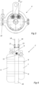
Figure 2 est une vue en couple longitudinale d'une unité d'explosion du système de déclenchement d'avalanches de lafigure 1 . -
Figure 3 est une vue de face de l'unité d'explosion de lafigure 2 . -
Figure 4 est une vue de côté d'une unité portative du système de déclenchement d'avalanches de lafigure 1 .
-
Figure 1 is a schematic view of an avalanche triggering system according to the present invention. -
Figure 2 is a longitudinal couple view of an explosion unit of the avalanche triggering system of thefigure 1 . -
Figure 3 is a front view of the explosion unit of thefigure 2 . -
Figure 4 is a side view of a portable unit of the avalanche triggering system of thefigure 1 .
Les
L'unité portative 3 comprend un dispositif de stockage de gaz 5 configuré pour stocker un gaz comburant et un gaz combustible. Le dispositif de stockage de gaz comporte plus particulièrement un réservoir de gaz comburant 6, tel qu'une bouteille de gaz comburant, et un réservoir de gaz combustible 7, tel qu'une bouteille de gaz combustible. De façon avantageuse, le réservoir de gaz combustible 6 et le réservoir de gaz comburant 7 sont amovibles de manière à permettre leurs remplacements lorsqu'ils sont vides. L'unité portative 3 peut par exemple comporter une ou plusieurs sangles de fixation 8 permettant de fixer de manière amovible le réservoir de gaz combustible 6 et le réservoir de gaz comburant 7 sur un corps de support 10 de l'unité portative 3.The
Le gaz comburant contenu dans le réservoir de gaz comburant 7 peut par exemple être du dioxygène, de l'ozone, du peroxyde d'hydrogène, des halogènes, ou tout autre gaz comburant, et le gaz combustible contenu dans le réservoir de gaz combustible 6 peut par exemple être du dihydrogène, du méthane, de l'éthane, du propane, du butane, du pentane, de l'acétylène, ou tout autre gaz combustible.The oxidizing gas contained in the oxidizing
L'unité portative 3 comporte en outre un circuit de distribution de gaz combustible 9 qui est relié fluidiquement au réservoir de gaz combustible 6, et un circuit de distribution de gaz comburant 11 qui est relié fluidiquement au réservoir de gaz comburant 7. De façon avantageuse, le circuit de distribution de gaz combustible 9 comporte successivement un premier détendeur, une première électrovanne et un première clapet anti-retour, et le circuit de distribution de gaz comburant 11 comporte successivement un deuxième détendeur, une deuxième électrovanne et un clapet anti-retour.The
L'unité portative 3 comporte également un premier raccord de connexion 12 qui est relié fluidiquement au circuit de distribution de gaz combustible 9, et un deuxième raccord de connexion 13 qui est relié fluidiquement au circuit de distribution de gaz comburant 7.The
Comme montré sur la
L'unité d'explosion 4 comporte en outre une cartouche amovible 21 qui est montée de manière amovible sur la partie de support 14, par exemple à l'aide d'un collier de fixation 22. La cartouche amovible 21 comporte notamment un carter de cartouche 23 et un capot de protection amovible 24 qui délimitent un logement de réception 25.The
L'unité d'explosion 4 comporte de plus une enveloppe souple 26 qui est logée dans le logement de réception 25 et qui est configurée pour être au moins partiellement remplie avec un mélange gazeux explosif formé par du gaz combustible et du gaz comburant provenant respectivement du réservoir de gaz combustible 6 et du réservoir de gaz comburant 7. L'enveloppe souple 26 comporte une chambre d'enveloppe 27 configurée pour contenir le mélange gazeux explosif, et une ouverture de remplissage 28 débouchant dans la chambre d'enveloppe 27.The
L'enveloppe souple 26 est plus particulièrement déformable entre une configuration de repos (voir la
Selon un mode de réalisation de l'invention, l'enveloppe souple 26 peut par exemple être en papier kraft et être pliée en accordéon lorsqu'elle est dans la configuration de repos. Selon un autre mode de réalisation de l'invention, l'enveloppe souple 26 peut par exemple être en matière plastique souple et être formée par un ballon gonflable.According to one embodiment of the invention, the
La cartouche amovible 21 comporte en outre une partie de stockage de poussières 29 qui délimite un logement interne 31 contenant des poussières combustibles 32. Les poussières combustibles 32 peuvent par exemple comporter des poussières d'origine agricole, telles que des poussières d'amidon, des poussières d'arachide, des poussières de bois, des poussières de cellulose, de la farine, de la fécule de maïs et des poussières de sucre. Les poussières combustibles 32 peuvent également par exemple comporter des poussières métalliques, tels des poussières d'aluminium ou de magnésium, ou des poussières chimiques, telles que des poussières d'acide acétylsalicylique, des poussières d'acide ascorbique et des poussières de 2,6-Di-tert-butylphenol. Les poussières combustibles 32 peuvent également comporter des poussières minérales, telles que des poussières de charbon ou du talc, ou des poussières plastiques ou de caoutchouc, telles que des poussières de polyacrylonitrile, des poussières de polycarbonate, des poussières de polyester, des poussières de polyéthylène, des poussières de polypropylène, des poussières de polystyrène et des poussières de polyuréthane.The
Selon le mode de réalisation représenté sur les figures, la partie de stockage de poussières 29 comporte une première portion d'extrémité tubulaire 33 qui est obturée par une paroi de séparation frangible 34 et qui est au moins partiellement insérée dans l'enveloppe souple 26, et une deuxième portion d'extrémité tubulaire 35 qui est opposée à la première portion d'extrémité tubulaire 33 et qui obturée par une paroi d'obturation frangible 36. La paroi de séparation frangible 34 est configurée pour séparer le logement de réception 25 et le logement interne 31, et plus particulièrement pour isoler fluidiquement le logement interne 31 de la chambre d'enveloppe 27 de l'enveloppe souple 26. De façon avantageuse, la paroi de séparation frangible 34 est formée par une membrane de séparation frangible, et la paroi d'obturation frangible 36 est formée par une membrane d'obturation frangible.According to the embodiment shown in the figures, the
Selon le mode de réalisation représenté sur les figures, la partie de support 14 comporte un alésage 37 dans lequel est monté de manière amovible la deuxième portion d'extrémité tubulaire 35, et la deuxième portion d'extrémité tubulaire 35, la paroi d'obturation frangible 36 et la partie de support 14 délimitent une chambre interne 38. L'unité d'explosion 4 comporte de façon avantageuse un circuit d'alimentation en gaz combustible 39 qui débouche dans la chambre interne 38 et qui est relié fluidiquement au conduit d'alimentation en gaz combustible 18 via le raccord de connexion primaire 16, et un circuit d'alimentation en gaz comburant 41 qui débouche dans la chambre interne 38 et qui est relié fluidiquement au conduit d'alimentation en gaz comburant 19 via le raccord de connexion secondaire 17.According to the embodiment shown in the figures, the
De façon avantageuse, la paroi d'obturation frangible 36 est configurée pour être rompue lorsque la pression de gaz dans la chambre interne 38 dépasse une pression prédéterminée, tandis que la paroi de séparation frangible 34 est configurée pour être rompue lorsque la pression de gaz dans le logement interne 31 dépasse une valeur de pression prédéterminée. En particulier, lorsque l'unité d'explosion 4 est alimentée en gaz comburant et en gaz combustible provenant du dispositif de stockage de gaz 5, la pression de gaz dans la chambre interne 38 s'élève jusqu'à provoquer la rupture de la paroi d'obturation frangible 36, puis la pression de gaz dans le logement interne 31 s'élève jusqu'à provoquer la rupture de la paroi de séparation frangible 34, ce qui entraîne la projection de poussières combustibles 32 dans l'enveloppe souple 26 et autorise un remplissage de l'enveloppe souple 26 avec le mélange explosif gazeux.Advantageously, the
L'unité d'explosion 4 comporte de plus un dispositif de mise à feu 42 qui est fixé à la partie de support 14 et qui est configuré pour déclencher l'explosion du mélange gazeux explosif contenu dans l'enveloppe souple 26. Selon le mode de réalisation représenté sur les figures, le dispositif de mise à feu 42 comporte une bougie d'allumage 43 qui est configurée pour générer une étincelle apte à provoquer l'inflammation du mélange gazeux explosif. Toutefois, la bougie d'allumage 43 pourrait être remplacée par tout autre dispositif de mise à feu permettant de provoquer l'inflammation du mélange gazeux explosif.The
Le système de déclenchement d'avalanches 2 comporte en outre une unité de commande 44 qui est configurée pour commander à distance le dispositif de mise à feu 42, et notamment pour commander la génération d'une étincelle lorsque le dispositif de mise à feu comporte la bougie d'allumage 43. L'unité de commande 44 est également configurée pour commander l'ouverture et la fermeture des première et deuxième électrovannes appartenant au circuit de distribution de gaz combustible 9 et au circuit de distribution de gaz comburant 11.The
Selon le mode de réalisation représenté sur les figures, l'unité de commande 44 est portée par l'unité portative 3, et comprend un microprocesseur apte à élaborer des consignes de commande. De façon avantageuse, l'unité portative 3 comporte un pupitre de commande 45 équipé d'une pluralité de bouton de commande.According to the embodiment shown in the figures, the
Le système de déclenchement d'avalanches 2 comporte également un dispositif de sécurité comportant un émetteur 46 qui est porté par l'unité d'explosion 4, et un récepteur 47 qui est porté par l'unité portative 3 et qui est configuré pour communiquer avec l'émetteur46. Le dispositif de sécurité comporte en outre une unité de traitement 48 qui est par exemple portée par l'unité portative 3 et qui est configurée pour calculer la distance de séparation séparant l'émetteur 46 du récepteur 47. L'unité de traitement 48 est plus particulièrement configurée pour empêcher une mise à feu du dispositif de mise à feu 42 si la distance de séparation est inférieure à la distance prédéterminée. Le dispositif de sécurité peut par exemple être un appareil de recherche de victimes d'avalanche, également nommé détecteur de victimes d'avalanches (DVA). Selon un mode de réalisation de l'invention, l'unité de commande 44 et l'unité de traitement 48 peuvent être formées par un même microprocesseur.The
La présence d'un tel dispositif de sécurité permet d'éviter tout déclenchement d'une explosion du mélange gazeux explosif si l'opérateur n'est pas situé à une distance minimale de l'unité d'explosion, et donc de limiter grandement les risques de blessure de l'opérateur.The presence of such a safety device makes it possible to avoid any triggering of an explosion of the explosive gas mixture if the operator is not located at a minimum distance from the explosion unit, and therefore to greatly limit the risk of injury to the operator.
Le système de déclenchement d'avalanches 2 comporte en outre un dispositif de stockage d'énergie électrique 49, tel qu'une batterie rechargeable, qui est disposé dans l'unité portative 3 et qui est configuré pour alimenter électriquement l'unité portative 49 et le dispositif de mise à feu 42. Le système de déclenchement d'avalanches 2 comporte également un câble d'alimentation électrique 51 qui relie électriquement le dispositif de mise à feu 42 à l'unité portative 3.The
De façon avantageuse, le système de déclenchement d'avalanches 2 comporte un câble de liaison qui s'étend entre l'unité portative 3 et l'unité d'explosion 4 et qui contient le conduit d'alimentation en gaz combustible 18, le conduit d'alimentation en gaz comburant 19 et le câble d'alimentation électrique 51.Advantageously, the
Le fonctionnement du système de déclenchement d'avalanches 2 selon la présente invention va maintenant être décrit.The operation of the
Lorsqu'un opérateur souhaite déclencher une avalanche préventive, il jette l'unité d'explosion 4, à l'aide de la poignée de préhension 15, à l'endroit précis où il veut déclencher l'avalanche, il actionne un bouton de commande du pupitre de commande 45 de telle sorte que l'unité de commande 44 commande l'ouverture, pendant une durée prédéterminée, des première et deuxième électrovannes du circuit de distribution de gaz combustible 9 et du circuit de distribution de gaz comburant 11. L'alimentation de l'unité d'explosion 4 avec du gaz combustible et du gaz comburant provoque successivement la rupture de la paroi de séparation frangible 36, la rupture de la paroi d'obturation frangible 34, la projection de poussières combustibles 32 dans l'enveloppe souple 26 et le remplissage de l'enveloppe souple 26 avec un mélange gazeux explosif. Lorsque le mélange explosif gazeux voulu est atteint, l'opérateur actionne un bouton de commande du pupitre de commande 45 de telle sorte que l'unité de commande 44 commande le dispositif de mise à feu 42 pour déclencher l'explosion du mélange gazeux explosif. L'onde de choc générée par l'explosion est transmise au manteau neigeux, et permet de détacher la neige et de déclencher une avalanche préventive.When an operator wishes to trigger a preventive avalanche, he throws the
Selon une variante de réalisation du système de déclenchement d'avalanches 2, l'unité d'explosion 4 pourrait être configurée pour être reliée à un drone et pour être transportée par un tel drone. Selon une telle variante de réalisation, l'unité d'explosion 4 pourrait être pourvue, à la place de la poignée de préhension 15 ou en plus la poignée de préhension 15, d'un élément de fixation prévu sur la partie de support 14 et configuré pour fixer de manière amovible la partie de support 14 au drone.According to an alternative embodiment of the
Ainsi, lorsqu'un opérateur souhaite déclencher une avalanche préventive à l'aide d'un tel système de déclenchement d'avalanches 2, il fixe l'unité d'explosion 4 au drone et commande un déplacement du drone jusqu'à l'endroit précis où il veut déclencher l'avalanche, puis il actionne un bouton de commande du pupitre de commande 45 de telle sorte que l'unité de commande 44 commande l'ouverture, pendant une durée prédéterminée, des première et deuxième électrovannes du circuit de distribution de gaz combustible 9 et du circuit de distribution de gaz comburant 11, de manière à remplir l'enveloppe souple 26 avec un mélange gazeux explosif.Thus, when an operator wishes to trigger a preventive avalanche using such an
Lorsque le mélange explosif gazeux voulu est atteint, l'opérateur actionne un bouton de commande du pupitre de commande 45 de telle sorte que l'unité de commande 44 commande le dispositif de mise à feu 42 pour déclencher l'explosion du mélange gazeux explosif.When the desired explosive gas mixture is reached, the operator activates a control button on the
Toutefois, l'opérateur pourrait également commander le remplissage de l'enveloppe souple 26 avec un mélange gazeux explosif avant de fixer l'unité d'explosion 4 au drone et de commander un déplacement du drone jusqu'à l'endroit précis où il veut déclencher l'avalanche.However, the operator could also order the filling of the
Comme il va de soi, l'invention ne se limite pas à la seule forme d'exécution de ce système de déclenchement d'avalanches, décrite ci-dessus à titre d'exemple, elle en embrasse au contraire toutes les variantes de réalisation définies par l'objet des revendications annexées.As it goes without saying, the invention is not limited to the sole form of execution of this avalanche triggering system, described above by way of example, on the contrary it embraces all the defined embodiment variants. by the subject matter of the appended claims.
Claims (14)
- An avalanche triggering system (2) including:- a portable unit (3) configured to be carried by an operator, the portable unit (3) comprising a gas storage device (5) configured to store an oxidizing gas and a combustible gas,- an explosion unit (4) which is configured to be launched by the operator and which is fluidly connected to the portable unit (3), the explosion unit (4) including a flexible envelope (26) which is configured to be at least partially filled with an explosive gas mixture formed by combustible gas and oxidizing gas coming from the gas storage device (5), the flexible envelope (26) being deformable between a rest configuration in which the flexible envelope (26) has a first inner volume and an inflated configuration in which the flexible envelope (26) has a second inner volume which is greater than the first inner volume and is at least partially filled with the explosive gas mixture, the explosion unit (4) further comprising an ignition device (42) which is configured to trigger the explosion of the explosive gas mixture contained in the flexible envelope (26), and- a control unit (44) which is configured to remotely control the ignition device (42).
- The avalanche triggering system (2) according to claim 1, wherein the gas storage device (5) includes a combustible gas tank (6) and an oxidizing gas tank (7).
- The avalanche triggering system (2) according to claim 2, wherein the combustible gas tank (6) and the oxidizing gas tank (7) are removable.
- The avalanche triggering system (2) according to claim 2 or 3, in which the portable unit (3) includes a combustible gas distribution circuit (9) which is fluidly connected to the combustible gas tank (6), and an oxidizing gas distribution circuit (11) which is fluidly connected to the oxidizing gas tank (7).
- The avalanche triggering system (2) according to claim 4, which includes a combustible gas supply conduit (18) which extends between the portable unit (3) and the explosion unit (4) and which is configured to fluidly connect the combustible gas distribution circuit (9) to the flexible envelope (26), and an oxidizing gas supply conduit (19) which extends between the portable unit (3) and the explosion unit (4) and which is configured to fluidly connect the oxidizing gas distribution circuit (11) to the flexible envelope (26).
- The avalanche triggering system (2) according to any one of claims 1 to 5, which further includes a safety device which is configured to prevent ignition of the ignition device (42) if a separation distance separating the explosion unit (3) from the portable unit (4) is less than a predetermined value.
- The avalanche triggering system (2) according to claim 6, wherein the safety device includes a transmitter (46) which is carried by one of the portable unit (3) and the explosion unit (4), a receiver (47) which is carried by the other of the portable unit (3) and the explosion unit (4) and which is configured to communicate with the transmitter (46), the safety device being configured to calculate the separation distance separating the transmitter (46) from the receiver (47) and to prevent an ignition of the ignition device if the separation distance is less than the predetermined distance.
- The avalanche triggering system (2) according to any one of claims 1 to 7, wherein the explosion unit (4) includes combustible dust (32) which is configured to be received in the flexible envelope (26).
- The avalanche triggering system (2) according to claim 8, wherein the explosion unit (4) includes an inner housing (31) containing the combustible dust (32), the explosion unit (4) being configured such that the combustible dust (32) is projected into the flexible envelope (26) by the oxidizing gas and the combustible gas coming from the gas storage device (5) when the flexible envelope (26) is at least partially filled with the explosive gas mixture.
- The avalanche triggering system (2) according to any one of claims 1 to 9, wherein the explosion unit (4) includes a removable cartridge (21) including a receiving housing (25) in which is housed the flexible envelope (26).
- The avalanche triggering system (2) according to claim 10, wherein the removable cartridge (21) includes a cartridge casing (23) and a removable protective cover (24) which at least partially delimit the receiving housing (25), the removable protective cover (24) being configured to be ejected from the cartridge casing (23) by the flexible envelope (26) when the flexible envelope (26) is deformed into the inflated configuration.
- The avalanche triggering system (2) according to any one of claims 1 to 11, wherein the control unit (44) is carried by the portable unit (3).
- The avalanche triggering system (2) according to any one of claims 1 to 12, wherein the portable unit (3) includes an electrical energy storage device (49) configured to electrically power the portable unit (3) and the ignition device (42).
- The avalanche triggering system (2) according to any one of claims 1 to 13, which includes a power supply cable (51) which electrically connects the ignition device (42) to the portable unit (3).
Applications Claiming Priority (2)
| Application Number | Priority Date | Filing Date | Title |
|---|---|---|---|
| FR1911258A FR3101940B1 (en) | 2019-10-10 | 2019-10-10 | Avalanche trigger system |
| PCT/FR2020/051772 WO2021069839A1 (en) | 2019-10-10 | 2020-10-08 | Avalanche triggering system |
Publications (2)
| Publication Number | Publication Date |
|---|---|
| EP4042097A1 EP4042097A1 (en) | 2022-08-17 |
| EP4042097B1 true EP4042097B1 (en) | 2024-03-06 |
Family
ID=69810931
Family Applications (1)
| Application Number | Title | Priority Date | Filing Date |
|---|---|---|---|
| EP20793766.5A Active EP4042097B1 (en) | 2019-10-10 | 2020-10-08 | Avalanche triggering system |
Country Status (7)
| Country | Link |
|---|---|
| US (1) | US20240085163A1 (en) |
| EP (1) | EP4042097B1 (en) |
| JP (1) | JP2022553916A (en) |
| CA (1) | CA3153939A1 (en) |
| CL (1) | CL2022000897A1 (en) |
| FR (1) | FR3101940B1 (en) |
| WO (1) | WO2021069839A1 (en) |
Family Cites Families (12)
| Publication number | Priority date | Publication date | Assignee | Title |
|---|---|---|---|---|
| FR2636729B1 (en) | 1988-09-19 | 1990-12-07 | Schippers Jacob | METHOD AND DEVICE FOR TRIGGERING AN AVALANCHE |
| FR2765320B1 (en) * | 1997-06-26 | 1999-09-17 | Jacob Schippers | DEVICE FOR CAUSING BREAKAGE OF A SNOW CORNICE |
| FR2771168B1 (en) * | 1997-11-17 | 1999-12-10 | Commissariat Energie Atomique | METHOD OF ARTIFICIAL TRIGGERING OF AN AVALANCHE AND DEVICE FOR CARRYING OUT SAID METHOD |
| FR2811420B1 (en) * | 2000-07-05 | 2003-01-17 | Giat Ind Sa | PROJECTILE FOR TRIGGERING AVALANCHES |
| US7707938B2 (en) * | 2005-05-16 | 2010-05-04 | Hisel Stanley D | Apparatus and method for avalanche control |
| FR2897931B1 (en) * | 2006-02-24 | 2008-05-09 | Technologie Alpine De Securite | AVALANCHE RELEASE DEVICE |
| AT509344B1 (en) * | 2007-10-19 | 2011-09-15 | Markus Stracke | DEVICE FOR THE TAXED DELIVERY OF AVALANCHES |
| FR2925152B1 (en) * | 2007-12-14 | 2013-06-28 | Technologie Alpine De Securite T A S | DEVICE FOR TRIGGERING AVALANCHES |
| FR2953922B1 (en) * | 2009-12-10 | 2011-12-09 | Technologie Alpine De Securite Tas | DEVICE FOR TRIGGERING AVALANCHES |
| FR2958739B1 (en) * | 2010-04-09 | 2012-05-11 | Technologie Alpine De Securite Tas | AVALANCHE RELEASE DEVICE |
| FR2964732B1 (en) * | 2010-09-14 | 2013-06-14 | Alp Artifices | PROJECTILE FOR AVALANCHE TRAPPING |
| US10968579B2 (en) * | 2018-07-26 | 2021-04-06 | Avy Blasters, LLC | Avalanche control device |
-
2019
- 2019-10-10 FR FR1911258A patent/FR3101940B1/en active Active
-
2020
- 2020-10-08 EP EP20793766.5A patent/EP4042097B1/en active Active
- 2020-10-08 CA CA3153939A patent/CA3153939A1/en active Pending
- 2020-10-08 JP JP2022521719A patent/JP2022553916A/en active Pending
- 2020-10-08 US US17/767,780 patent/US20240085163A1/en active Pending
- 2020-10-08 WO PCT/FR2020/051772 patent/WO2021069839A1/en active Application Filing
-
2022
- 2022-04-07 CL CL2022000897A patent/CL2022000897A1/en unknown
Also Published As
| Publication number | Publication date |
|---|---|
| CA3153939A1 (en) | 2021-04-15 |
| FR3101940A1 (en) | 2021-04-16 |
| JP2022553916A (en) | 2022-12-27 |
| WO2021069839A1 (en) | 2021-04-15 |
| FR3101940B1 (en) | 2021-10-15 |
| US20240085163A1 (en) | 2024-03-14 |
| EP4042097A1 (en) | 2022-08-17 |
| CL2022000897A1 (en) | 2023-01-13 |
Similar Documents
| Publication | Publication Date | Title |
|---|---|---|
| CA2432050C (en) | Infra-red emitting decoy flare | |
| WO2009080977A2 (en) | Avalanche triggering system | |
| FR2704053A1 (en) | Cartridge in two separable parts. | |
| EP4042097B1 (en) | Avalanche triggering system | |
| WO2020236848A1 (en) | Explosive detonating system and components | |
| EP0991912B1 (en) | Device for provoking an avalanche | |
| EP1205727B1 (en) | Pyrotechnic delay initiator | |
| EP0991911B1 (en) | Device for provoking the collapse of a snow cornice | |
| EP0109161B1 (en) | Blasting-cartridge case | |
| FR2811420A1 (en) | PROJECTILE FOR TRIGGERING AVALANCHES | |
| NO164195B (en) | FUEL STRUCTURE FOR A ROCKET ENGINE WITH SOLID FUEL. | |
| EP1530020B1 (en) | Ignition device of at least two pyrotechnical compositions or propulsive charges of a projectile | |
| FR2559069A1 (en) | FIRE AND EXPLOSION SAFETY DEVICE AND METHOD FOR THE STORAGE OF COMBUSTIBLE OR EXPLOSIVE MATERIALS | |
| FR2551198A1 (en) | Device for neutralising mine igniters | |
| EP1961459A1 (en) | Fire extinguishing device | |
| EP4263348A1 (en) | Device for generating a shock wave | |
| EP0943887A1 (en) | Conversion kit enabling the conversion of an explosive projectile to a concrete piercing projectile and projectile obtained by conversion | |
| FR2469690A1 (en) | Distress flare providing visual and electromagnetic signal - has electromagnetic lures made from metallised glass fibres and dispersed by combustion of charge providing flame | |
| NO770850L (en) | ROCKET ENGINE. | |
| EP2578077A1 (en) | Ignition device | |
| FR2758879A1 (en) | Tear=gas grenade launcher | |
| CN104154564A (en) | Gas well ignition device and ignition bomb | |
| FR2988389A1 (en) | Composition, useful in an explosive charge and projectile to release avalanches on terrestrial target e.g. winter sports stations, comprises potassium perchlorate and aluminum powder | |
| CH359383A (en) | Mine | |
| FR2507763A1 (en) | Mobile anti-tank rocket launchers having anti-flash guards - involving components of expanded polyethylene opt. supported on polyamide fabric |
Legal Events
| Date | Code | Title | Description |
|---|---|---|---|
| STAA | Information on the status of an ep patent application or granted ep patent |
Free format text: STATUS: UNKNOWN |
|
| STAA | Information on the status of an ep patent application or granted ep patent |
Free format text: STATUS: THE INTERNATIONAL PUBLICATION HAS BEEN MADE |
|
| PUAI | Public reference made under article 153(3) epc to a published international application that has entered the european phase |
Free format text: ORIGINAL CODE: 0009012 |
|
| STAA | Information on the status of an ep patent application or granted ep patent |
Free format text: STATUS: REQUEST FOR EXAMINATION WAS MADE |
|
| 17P | Request for examination filed |
Effective date: 20220428 |
|
| AK | Designated contracting states |
Kind code of ref document: A1 Designated state(s): AL AT BE BG CH CY CZ DE DK EE ES FI FR GB GR HR HU IE IS IT LI LT LU LV MC MK MT NL NO PL PT RO RS SE SI SK SM TR |
|
| DAV | Request for validation of the european patent (deleted) | ||
| DAX | Request for extension of the european patent (deleted) | ||
| GRAP | Despatch of communication of intention to grant a patent |
Free format text: ORIGINAL CODE: EPIDOSNIGR1 |
|
| STAA | Information on the status of an ep patent application or granted ep patent |
Free format text: STATUS: GRANT OF PATENT IS INTENDED |
|
| INTG | Intention to grant announced |
Effective date: 20230508 |
|
| GRAS | Grant fee paid |
Free format text: ORIGINAL CODE: EPIDOSNIGR3 |
|
| GRAA | (expected) grant |
Free format text: ORIGINAL CODE: 0009210 |
|
| STAA | Information on the status of an ep patent application or granted ep patent |
Free format text: STATUS: THE PATENT HAS BEEN GRANTED |
|
| AK | Designated contracting states |
Kind code of ref document: B1 Designated state(s): AL AT BE BG CH CY CZ DE DK EE ES FI FR GB GR HR HU IE IS IT LI LT LU LV MC MK MT NL NO PL PT RO RS SE SI SK SM TR |
|
| REG | Reference to a national code |
Ref country code: CH Ref legal event code: EP |
|
| REG | Reference to a national code |
Ref country code: IE Ref legal event code: FG4D Free format text: LANGUAGE OF EP DOCUMENT: FRENCH |
|
| REG | Reference to a national code |
Ref country code: DE Ref legal event code: R096 Ref document number: 602020026918 Country of ref document: DE |