EP4041048B1 - Systeme und verfahren zur änderung der blickrichtung bei videogesteuerten klinischen verfahren mittels echtzeit-bildverarbeitung - Google Patents
Systeme und verfahren zur änderung der blickrichtung bei videogesteuerten klinischen verfahren mittels echtzeit-bildverarbeitung Download PDFInfo
- Publication number
- EP4041048B1 EP4041048B1 EP20874325.2A EP20874325A EP4041048B1 EP 4041048 B1 EP4041048 B1 EP 4041048B1 EP 20874325 A EP20874325 A EP 20874325A EP 4041048 B1 EP4041048 B1 EP 4041048B1
- Authority
- EP
- European Patent Office
- Prior art keywords
- image
- camera
- source
- point
- target
- Prior art date
- Legal status (The legal status is an assumption and is not a legal conclusion. Google has not performed a legal analysis and makes no representation as to the accuracy of the status listed.)
- Active
Links
Images


Classifications
-
- A—HUMAN NECESSITIES
- A61—MEDICAL OR VETERINARY SCIENCE; HYGIENE
- A61B—DIAGNOSIS; SURGERY; IDENTIFICATION
- A61B1/00—Instruments for performing medical examinations of the interior of cavities or tubes of the body by visual or photographical inspection, e.g. endoscopes; Illuminating arrangements therefor
- A61B1/00163—Optical arrangements
- A61B1/00174—Optical arrangements characterised by the viewing angles
- A61B1/00179—Optical arrangements characterised by the viewing angles for off-axis viewing
-
- A—HUMAN NECESSITIES
- A61—MEDICAL OR VETERINARY SCIENCE; HYGIENE
- A61B—DIAGNOSIS; SURGERY; IDENTIFICATION
- A61B1/00—Instruments for performing medical examinations of the interior of cavities or tubes of the body by visual or photographical inspection, e.g. endoscopes; Illuminating arrangements therefor
- A61B1/00002—Operational features of endoscopes
- A61B1/00004—Operational features of endoscopes characterised by electronic signal processing
- A61B1/00009—Operational features of endoscopes characterised by electronic signal processing of image signals during a use of endoscope
- A61B1/000094—Operational features of endoscopes characterised by electronic signal processing of image signals during a use of endoscope extracting biological structures
-
- A—HUMAN NECESSITIES
- A61—MEDICAL OR VETERINARY SCIENCE; HYGIENE
- A61B—DIAGNOSIS; SURGERY; IDENTIFICATION
- A61B1/00—Instruments for performing medical examinations of the interior of cavities or tubes of the body by visual or photographical inspection, e.g. endoscopes; Illuminating arrangements therefor
- A61B1/00002—Operational features of endoscopes
- A61B1/00004—Operational features of endoscopes characterised by electronic signal processing
- A61B1/00009—Operational features of endoscopes characterised by electronic signal processing of image signals during a use of endoscope
- A61B1/000096—Operational features of endoscopes characterised by electronic signal processing of image signals during a use of endoscope using artificial intelligence
-
- A—HUMAN NECESSITIES
- A61—MEDICAL OR VETERINARY SCIENCE; HYGIENE
- A61B—DIAGNOSIS; SURGERY; IDENTIFICATION
- A61B1/00—Instruments for performing medical examinations of the interior of cavities or tubes of the body by visual or photographical inspection, e.g. endoscopes; Illuminating arrangements therefor
- A61B1/00002—Operational features of endoscopes
- A61B1/00043—Operational features of endoscopes provided with output arrangements
- A61B1/00045—Display arrangement
- A61B1/0005—Display arrangement combining images e.g. side-by-side, superimposed or tiled
-
- A—HUMAN NECESSITIES
- A61—MEDICAL OR VETERINARY SCIENCE; HYGIENE
- A61B—DIAGNOSIS; SURGERY; IDENTIFICATION
- A61B1/00—Instruments for performing medical examinations of the interior of cavities or tubes of the body by visual or photographical inspection, e.g. endoscopes; Illuminating arrangements therefor
- A61B1/00163—Optical arrangements
- A61B1/00174—Optical arrangements characterised by the viewing angles
- A61B1/00183—Optical arrangements characterised by the viewing angles for variable viewing angles
-
- A—HUMAN NECESSITIES
- A61—MEDICAL OR VETERINARY SCIENCE; HYGIENE
- A61B—DIAGNOSIS; SURGERY; IDENTIFICATION
- A61B1/00—Instruments for performing medical examinations of the interior of cavities or tubes of the body by visual or photographical inspection, e.g. endoscopes; Illuminating arrangements therefor
- A61B1/00163—Optical arrangements
- A61B1/00188—Optical arrangements with focusing or zooming features
-
- G—PHYSICS
- G02—OPTICS
- G02B—OPTICAL ELEMENTS, SYSTEMS OR APPARATUS
- G02B23/00—Telescopes, e.g. binoculars; Periscopes; Instruments for viewing the inside of hollow bodies; Viewfinders; Optical aiming or sighting devices
- G02B23/24—Instruments or systems for viewing the inside of hollow bodies, e.g. fibrescopes
- G02B23/2476—Non-optical details, e.g. housings, mountings, supports
- G02B23/2484—Arrangements in relation to a camera or imaging device
-
- G—PHYSICS
- G06—COMPUTING OR CALCULATING; COUNTING
- G06T—IMAGE DATA PROCESSING OR GENERATION, IN GENERAL
- G06T15/00—Three-dimensional [3D] image rendering
- G06T15/10—Geometric effects
- G06T15/20—Perspective computation
- G06T15/205—Image-based rendering
-
- G—PHYSICS
- G06—COMPUTING OR CALCULATING; COUNTING
- G06T—IMAGE DATA PROCESSING OR GENERATION, IN GENERAL
- G06T3/00—Geometric image transformations in the plane of the image
- G06T3/18—Image warping, e.g. rearranging pixels individually
-
- G—PHYSICS
- G06—COMPUTING OR CALCULATING; COUNTING
- G06T—IMAGE DATA PROCESSING OR GENERATION, IN GENERAL
- G06T7/00—Image analysis
- G06T7/10—Segmentation; Edge detection
- G06T7/13—Edge detection
-
- G—PHYSICS
- G06—COMPUTING OR CALCULATING; COUNTING
- G06T—IMAGE DATA PROCESSING OR GENERATION, IN GENERAL
- G06T7/00—Image analysis
- G06T7/30—Determination of transform parameters for the alignment of images, i.e. image registration
- G06T7/33—Determination of transform parameters for the alignment of images, i.e. image registration using feature-based methods
-
- G—PHYSICS
- G06—COMPUTING OR CALCULATING; COUNTING
- G06T—IMAGE DATA PROCESSING OR GENERATION, IN GENERAL
- G06T7/00—Image analysis
- G06T7/80—Analysis of captured images to determine intrinsic or extrinsic camera parameters, i.e. camera calibration
-
- G—PHYSICS
- G06—COMPUTING OR CALCULATING; COUNTING
- G06T—IMAGE DATA PROCESSING OR GENERATION, IN GENERAL
- G06T2207/00—Indexing scheme for image analysis or image enhancement
- G06T2207/10—Image acquisition modality
-
- G—PHYSICS
- G06—COMPUTING OR CALCULATING; COUNTING
- G06T—IMAGE DATA PROCESSING OR GENERATION, IN GENERAL
- G06T2207/00—Indexing scheme for image analysis or image enhancement
- G06T2207/10—Image acquisition modality
- G06T2207/10068—Endoscopic image
-
- G—PHYSICS
- G06—COMPUTING OR CALCULATING; COUNTING
- G06T—IMAGE DATA PROCESSING OR GENERATION, IN GENERAL
- G06T2210/00—Indexing scheme for image generation or computer graphics
- G06T2210/41—Medical
Definitions
- the disclosure generally relates to the fields of computer vision and image processing, and in particular, but not by way of limitation, the presented disclosed embodiments can be used for enhanced visualization in video guided minimally invasive clinical procedures of surgery and diagnosis, such as arthroscopy, laparoscopy or endoscopy, for the purposes of changing the direction of view of the surgical camera with an endoscopic lens, in which case the system renders the view that would be acquired by a physical scope with a different lens cut from the one that is being effectively used, or performing zoom along an arbitrary viewing direction without decreasing the image field-of-view or losing image contents.
- video guided minimally invasive clinical procedures of surgery and diagnosis such as arthroscopy, laparoscopy or endoscopy
- the anatomical cavity of interest is accessed through small incisions designated as surgical ports.
- One of these ports gives access to a video camera equipped with a rigid endoscope that enables the surgeon to visualize the interior of the cavity for the purpose of guidance during procedures of surgery or diagnosis.
- the rigid endoscope is an elongated tubular structure that is inserted into the body cavity.
- the endoscope typically comprises an objective lens at the distal end, an image-forwarding system, such as a series of spaced-apart lenses, and an ocular lens at the proximal end where a camera means, such as a charge coupled device (CCD) chip, is usually mounted.
- the image-forwarding system serves to forward the image from distal to proximal end. The camera receives this image and produces a signal for a video display to be observed by the surgeon.
- CCD charge coupled device
- the rigid endoscope also referred to in here as lens scope or endoscopic lens
- the rigid endoscope is used in different specialties and, depending on its features and application field, it can be alternatively named as arthroscope (orthopeadics), laparoscope (abdominal surgery), cystoscope (bladder), sinuscope (ENT), neuroscope, etc.
- arthroscope orthopeadics
- laparoscope laparoscope
- cystoscope bladedder
- sinuscope ENT
- neuroscope etc.
- the endoscopic camera that results from combining a rigid endoscope with a camera means, has specific features that are uncommon in conventional cameras.
- the optics are usually exchangeable for the purpose of easy sterilization, with the endoscope being assembled in the camera head by the surgeon before starting the procedure.
- the ocular lens (or eye-piece) in the proximal end of the endoscope is assembled to the camera using a connector that typically allows the user to rotate the scope with respect to the camera head by an angle ⁇ .
- This is a rotation in azimuth around a longitudinal axis of the endoscope, henceforth referred to as mechanical axis, that is close, but not necessarily coincident, with the symmetry axis of the tubular structure.
- the rigid endoscope typically has a Field Stop Mask (FSM) somewhere along the image forwarding system that causes the acquired image to have meaningful content in a circular region which is surrounded by a black frame (which black frame is illustrated in diagonal lines in the figures of this application).
- FSM Field Stop Mask
- the design of the FSM is such that there is usually a mark in the circular boundary defined by the image-frame transition that enables the surgeon to infer the angle in azimuth ⁇ . This mark in the periphery of the circular image will be henceforth referred to as the notch.
- the lens in the distal end of the endoscope is often mounted in such a way that the optical axis of the entire lens system has an angular offset from the longitudinal or mechanical axis of the scope.
- This angle ⁇ between optical and mechanical axes is usually referred to as the lens cut of the endoscope. If the lens cut is different from zero, then the optical and mechanical axes are not aligned and the surgeon can vary the direction of view in azimuth by rotating the scope around the mechanical axis without having to move the camera head.
- variable DoV Direction of View
- the rigid endoscopes currently used in clinic empower the surgeon with the possibility of varying the DoV by performing a rotation in azimuth of the lens scope, which causes the optical axis to describe a cone in space with apex close to the projection center O (the cone of DoV).
- the half-angle of this cone is defined by the lens cut ⁇ that is fixed and known a priori by the surgeon. Surgeons rely heavily on the prior knowledge of the lens cut of a particular endoscope to dependably know what the anatomy should look like.
- endoscopes with different angular offsets from the longitudinal or mechanical axis, with the most commonly used lens cuts being 0°, 30° , 45° and 70°.
- Surgical procedures typically require endoscopes of most of these cut angles with specific emphasis on one of them.
- endoscopes typically require endoscopes of most of these cut angles with specific emphasis on one of them.
- the preference in knee arthroscopy the preference goes for a lens cut of 30° that provides both a good forward view and a certain amount of lateral viewing
- hip arthroscopy the lens cut of choice is usually 70° because the anatomic cavity is much narrower.
- the preference in laparoscopy can vary between a lens cut of 0° (forward looking scope) or 30°.
- the insertion of off-angle endoscopes can be dangerous because they are not looking in the direction they are being inserted, and neurosurgeons often refrain from using endoscopes with 45° or 70° lens cuts because they are afraid of blindly thrusting the endoscope into delicate tissue.
- the rigid endoscopes commonly used in medicine enable the surgeon to vary the DoV in azimuth (angle ⁇ ) but not in inclination or elevation (angle ⁇ ), in which case the optical axis is constrained to move in a cone with symmetry axis aligned with the mechanical axis and angle defined by the lens cut ⁇ (the cone of DoV). It follows from the discussion that unconstrained variation of DoV would be highly beneficial namely by allowing the surgeon to change the lateral viewing angle (the lens cut ⁇ ) without having to physically change the endoscope in the mid procedure.
- An alternative manner for accomplishing unconstrained variation of DoV is to employ computational means to process the endoscopic image or video. It is well known in the field of computer vision that a change in the DoV corresponds to a rotation of the camera around an axis going through its projection center, and that the virtual image that would be acquired by such rotated camera can be rendered by warping the real source image by a suitable homographic map often referred to as a collineation of the plane at infinity.
- Patent Applications US005313306A , US 20154/0065799A1 , and EP3130276A1 that disclosed rigid endoscopes with wide angle lenses for hemispherical Field-of-View (FoV), that are combined with computer means to render images with a variable DoV that cover selected parts of the FoV.
- the result are camera systems with controllable pan-and-tilt orientation where the user commands the viewing direction both in X (azimuth) and Y (elevation) using electronic means.
- an endoscopy system with a DoV that can vary both in azimuth ⁇ and inclination ⁇ , where the variation in azimuth is accomplished by the standard mechanical means, i.e. by rotating the rigid endoscope with respect to the camera head, and the variation in inclination is accomplished by electronic or computer means, i.e. by using real-time processing to render images with the targeted viewing direction.
- the presently disclosed embodiments disclose a software-based system that enables to change the viewing direction of a particular scope by an arbitrary amount ⁇ such that the cutting angle of the lens (or lens cut) virtually switches from ⁇ to ⁇ + ⁇ . This is accomplished in a seamless, fully automatic manner that is realistic for the user that can physically rotate the endoscope in azimuth around its longitudinal axis during operation.
- a software-based system processes the images and video acquired by an endoscopy camera equipped with a lens with a wide Field of View (FoV) to empower the surgeon with electronic switch between two or more virtual endoscopes with different lens cuts.
- FoV Field of View
- the presently disclosed embodiments disclose a method that, given the desired lens cuts ⁇ 1 and ⁇ 2 and FoVs ⁇ 1 and ⁇ 2 of the two targeted virtual endoscopes, determines the lens cut ⁇ and FoV ⁇ of the source camera such that the acquired images and video are well suited to be used as input in the disclosed image processing methods for rendering realistic virtual images and video.
- the presently disclosed embodiments disclose a method that, given arbitrary pre-sets for the virtual camera, not only in terms of desired shift in lens cut ⁇ , but also in terms of image resolution m ⁇ n, field-of-view ⁇ , and amount of image distortion ⁇ , assures that the corresponding virtual view is correctly rendered without top or bottom regions without content (empty regions) by automatically adjusting the focal length f ⁇ and position of principal point ⁇ at each frame time instant.
- the presently disclosed embodiments disclose a method that enables to control the amount of image radial distortion to either work with distortion free images for optimal perception of scene depth, or to select a Region of Interest by performing image zoom along arbitrary viewing directions by either changing the amount of radial distortion ⁇ , in which case the zoom is accomplished without loss in the field of view (FoV), or by changing the focal length f ⁇ .
- the systems and methods may be used for clinical procedures including, but not limited to, arthroscopy, laparoscopy, endoscopy or other surgical procedures including minimally invasive orthopedic surgery procedures.
- the systems and methods can be used with real-time image processing or delayed image processing.
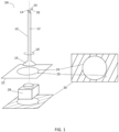
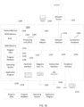
- FIG. 1 schematizes an endoscopic camera 34, to be used in the aforementioned video guided clinical procedures, that consists of an endoscope 10 whose proximal end 16 is assembled to a camera head 28 by means of a connector that allows the endoscope 10 to perform a rotation in azimuth by an angle ⁇ 18 around the mechanical axis 12.
- the endoscope 10 typically contains a Field Stop Mask (FSM) along the image forwarding system that causes the light that is forwarded from the distal end 14 to the proximal end 16 to form a canonical image 22 containing a circular boundary 24 and a notch 26.
- FSM Field Stop Mask
- the camera head 28 transforms the canonical image 22 into an image in pixels 30 also presenting a circular boundary 24 and a notch 26.
- the direction of view (DoV) 36 changes while rotating the endoscope 10 with respect to the camera head 28 because of the lens at the distal end 14 that causes the optical axis 36 and the mechanical axis 12 to be misaligned by an angle ⁇ denoted as lens cut 20.
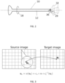
- the rotation in azimuth 18 around the mechanical axis 12 of the endoscope 10 causes the optical axis 36 to describe a cone in space 32 (the cone of DoV) whose half-angle is the lens cut 20, as illustrated in FIG. 2 .
- 2D and 3D vectors are written in bold lower and upper case letters, respectively.
- Functions are represented by lower case italic letters, and angles by lower case Greek letters.
- Points and other geometric entities in the plane are represented in homogeneous coordinates, as is commonly done in projective geometry, with 2D linear transformations in the plane being represented by 3x3 matrices and equality being up to scale.
- the symbol when representing functions, the symbol ; is used to distinguish between variables (that appear to the left of ;) and parameters (that appear to the right of ;) of the function.
- different sections of the text are referenced by their paragraphs' numbers using the symbol ⁇ .
- the disclosed methods and systems for the rendering of virtual views with an arbitrary shift in the inclination of viewing direction relate with image warping techniques, in particular with software based methods to create a virtual Pan-Tilt-Zoom (PTZ) camera from a wide Field of View (FoV), panoramic camera.
- PTZ Pan-Tilt-Zoom
- FoV Field of View
- the image that would be acquired by the PTZ camera is rendered from the image acquired by the panoramic camera (the source image) through a function that maps pixels in one image into pixels in the other.
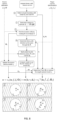
- w be the function that transforms pixel coordinates ut in the target image into pixel coordinates u s in the source image, as illustrated in FIG. 3 .
- the color value of pixel u t in the target image can be determined by using any type of interpolation approach in the spatial or in the frequency domains, which includes, but is not limited to, nearest neighbors, next neighbors, previous neighbors, bi-linear, bi-cubic, Lanczos, bi-cubic b-spline, Mitchell-Netravali, Catmull-Rom, Kriging based, wavelet based, or edge-directed interpolation.
- Data driven interpolation filters learned using machine learning or deep learning can also be employed for obtaining the color value of u t .
- the existing warping techniques include, but are not limited to, direct mapping, inverse mapping, warping by re-sampling in the continuous or discrete image domain, warping by re-sampling and filtering, warping using a look-up table, warping using decomposable transformations and learned warping transformations.
- the warping function w is the composition of functions c s and c t , corresponding to the camera models of the source and target cameras, respectively, with function m, which is the camera motion.
- the camera models c s and c t describe the mapping between the canonical image 22 in millimeters and the image in pixels 30. Since the source camera is a real camera, c s can be determined using an appropriate calibration method.
- the target camera ct is chosen so that the desired imaging features (resolution, zoom, FoV, etc) are predefined.
- Concerning function m it describes the relative motion between virtual (target) and real (source) cameras. In more detail, it represents the rotation undergone by the virtual camera in 3D space that causes an homography mapping in projective coordinates between the canonical images of the source and target cameras.
- Warping images acquired with endoscopic cameras is significantly more challenging than doing so with images acquired with conventional cameras because of two main reasons.
- the camera model c s changes in every frame time instant due to the relative rotation of the endoscopic lens with respect to the camera head, and this must be taken into account in building the warping function w .
- the motion model m depends not only on the desired change in elevation ⁇ but also in the mechanical change in azimuth ⁇ that must be measured at every frame time instant.
- This section introduces the endoscopic camera model c by describing the model of a general camera presenting radial distortion introduced by the optics, providing an overview of relevant concepts and explaining how the endoscopic camera can be described with an adaptive model that is updated at every frame time instant.
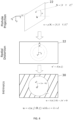
- FIG. 4 schematizes the different steps that comprise the camera model function c.
- the application of the intrinsic parameters converts points in millimeters x' into points u in the image in pixels 30.
- the distortion function d is generic, meaning that it can be any distortion model in the literature such as Brown's polynomial model, the rational model, the fish-eye model, or the division model with one or more parameters, in which case ⁇ is a scalar or a vector, respectively.
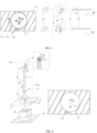
- the rotation of the endoscope 10 with respect to the camera head 28 causes the principal point O, the center C of the circular boundary 24 and the notch 26, denoted as P, to rotate in the image in pixels 30 around a point Q, as illustrated in FIG. 5 .
- O and C rotate around Q because they are usually not coincident due to mechanical tolerances during lens manufacturing.
- C is the center of the circular boundary that depends on how the FSM is placed with respect to the lens rod
- Q is the intersection of the mechanical axis 12 with the image plane, which depends on the eye-piece, the coincidence of all three points occurs when the eye-piece and the FSM are perfectly aligned with the lens rod.
- the misalignment between Q and C causes the boundary to change positions in the image and C to move in a circle around Q while the lens rotates.
- O also describes a circular trajectory around Q.
- both the calibration parameters f, O, ⁇ for a reference azimuth position ⁇ 0 and the rotation center Q are known a priori, such that if rotation ⁇ i with respect to ⁇ 0 is estimated at each frame time instant i, then the calibration parameters f, O i , ⁇ can be determined as previously described. It is relevant to note that if O is coincident with Q, then O i in every frame i will also be coincident with Q and thus this adaptation of the camera model c to the rotation of the scope is unnecessary. However, the misalignment between these entities occurs frequently due to mechanical tolerances in building the optics, as discussed previously. Since the effect of this misalignment in the calibration parameters is not negligible, it must be taken into account in practice.
- FIG. 6 provides an illustrative scheme to better explain the most relevant concepts.
- a change in the DoV of a generic camera can be accomplished by rotating the camera around an axis going through its projection center.
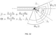
- This direction n i 42 is the normal to a plane ⁇ i 40, henceforth referred to as the reference plane, that is defined by the mechanical and optical axes, which, in ideal conditions, are coplanar but not coincident because of the non-zero lens cut. Since the optical axis 36 defines the DoV that changes with the rotation in azimuth 18, the motion model m, which is a 3D rotation of ⁇ around axis n i 42, can vary at every frame time instant i and must be estimated accordingly.
- the reference plane ⁇ i 40 is projected into a line n i 38 in the image in pixels 30.
- n i on-the-fly by detecting line n i 38 in every frame i and back-projecting it into the 3D space.
- plane ⁇ i 40 contains both the optical and the mechanical axes and intersects the FSM in the notch, whose purpose is to inform the surgeon about the direction of the lens cut.
- These conditions hold if and only if points Q, O i and P i in the image in pixels 30 are collinear and, in this case, line n i 38 is the line that contains all three points Q, O i and P i . In real conditions, this does not usually happen due to the mechanical tolerances in lens manufacturing, leading to a non-coplanarity of the optical and mechanical axes and/or plane ⁇ i 40 not going exactly through the notch of the FSM.
- n i 38 is the line defined by the optical axis O i and the notch P i .
- line n i 38 can be obtained by determining the line that goes through points Q and O i or C i and O i , in which case points Q and C i replace P i in the previous equation, respectively.
- the FSM contains more than one notch, which is useful for guaranteeing that at least one notch is always visible in the image, being able to detect multiple notches whose relative location is known and that are identified by their different shapes and sizes.
- a distance r measured in the image in pixels 30 between any point and the principal point O corresponds to an angle ⁇ in 3D that depends on both f and ⁇ and that can be computed using Equation 1.
- d be the length of the line segment whose endpoints are the two intersections of the boundary with the line n 38 in FIG. 7 that goes through the principal point O. This length d is referred to as diameter despite not corresponding to the diameter of the circular boundary, as this only happens in case the principal point O is coincident with the boundary center C.
- angles ⁇ l and ⁇ u can be determined from Equation 1.
- Any line n going through the principal point O defines a different diameter d, and FIG. 7 shows the particular case of n going through the notch P.
- This section presents the method disclosed in this disclosure for changing the DoV by rendering the video that would be acquired by a virtual camera with predefined characteristics located in the same 3D position as a real endoscopic camera.
- I i be frame i acquired by the real endoscopic camera, henceforth referred to as the source camera, whose endoscope has a lens cut ⁇ and rotates in azimuth around a mechanical axis that intersects the image plane in the rotation center Q.
- the endoscopic camera's calibration for a reference angular position ⁇ 0 corresponding to a particular notch position P, is known, meaning that its focal length f, radial distortion ⁇ and principal point O have been determined.
- the purpose of this method is to render an image Î i with resolution m ⁇ n and a circular boundary with diameter d ⁇ centered in point ⁇ that would be acquired by a virtual camera, henceforth referred to as the target camera, with a lens cut ⁇ , Field-of-View 0, and distortion ⁇ placed in the same 3D location as the source camera.
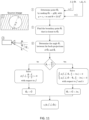
- the method starts by detecting the boundary with center C i and notch P i in image I i .
- the rotation in azimuth ⁇ i as the angle defined by points P i , Q and P
- Line n i which is the projection of the reference plane ⁇ i introduced in ⁇ [0060]-[0064] in the image plane, is determined as the line that goes through points O i and P i .
- this mapping function w may implement any method for image warping or pixel value interpolation.
- the disclosed method for changing the DoV assumes that the calibration parameters of the source camera for the reference position in azimuth ⁇ 0 are known in advance. These can be determined in several different ways, which include, but are not limited to, using a set of calibration parameters predetermined in factory or representative of a set of similar endoscopic cameras and using an appropriate calibration method for performing calibration in the Operating Room before the medical procedure, such as the one disclosed in U.S. Patent No. 9,438,897 (application no. 14/234,907 ) entitled "Method and apparatus for automatic camera calibration using one or more images of a checkerboard pattern".
- the presently disclosed method also assumes that the rotation center Q is known a priori. However, this is not a strict requirement since Q may be determined on-the-fly from points P i and/or C i detected in successive frames, using the method disclosed in US Application No. US Application No. 62/911,950 .
- Another alternative is to determine the position of the principal point O i in every frame time instant i by making use of an estimate for the principal point given in a normalized reference frame that is attached to the circular boundary. In this case, since O i is obtained directly from the normalized estimate of the principal point, as disclosed in US Application No. US Application No. 62/911,950 , it is not required to know the rotation center Q or the angular displacement in azimuth ⁇ i a priori.
- the estimation of the angular displacement in azimuth ⁇ i is performed using exclusively image processing methods.
- estimation approaches that can be employed to measure the changes in rotation in azimuth of the scope with respect to the camera-head at every frame time instant. These include the use of sensing devices such as a rotary encoder attached to the camera head or an optical tracking system for determining the position of an optical marker attached to the scope cylinder.
- the method for changing the DoV disclosed herein may be used for different purposes by setting the parameters of the target camera to desired values.
- the distortion of the target camera ⁇ is set to zero, the images Î i rendered by the target camera will be distortion-free images.
- the image boundary can also take any other desired geometric shape, such as, but not limited to, a conic shape, a rectangular shape, a hexagonal shape or any other polygonal shape.
- the disclosed warping function w is the composition of three functions: the camera model c s , for which the parameters are the calibration parameters of the real source camera at the current frame i, the motion model m that depends on the desired change in inclination ⁇ and orientation n i of the reference plane with respect to camera-head, and the camera model ct for the virtual target camera that must be such that the FoV is ⁇ for an image distortion of ⁇ and image diameter d ⁇ .
- Setting B has the drawback that the FoV of the target image can be substantially smaller than what was specified, which is in general an issue in terms of application ( FIG. 10(b) LEFT).
- This disclosure discloses an alternative method to choose the focal length and principal point of the target image that conciliates the change in inclination of the DoV by an angle ⁇ , with the rendering of an image with the desired FoV ⁇ and no empty regions ( FIG. 10(c) RIGHT).
- the different steps that comprise this novel method are provided in the scheme of FIG. 11 .
- the strategy serves to compensate the lack of visual contents in the top or bottom of the source image by the visual contents that are available below or above, in case ⁇ ⁇ 0 or ⁇ > 0, respectively.
- the shift in the DoV be a positive angular offset ⁇ > 0 ( FIG. 10(c) LEFT) such that the limiting viewing angle ⁇ i is measured towards the notch (the down direction). Since the FoV of the target image in the down direction has to be decreased by an amount 0 - ⁇ i to avoid the creation of an empty region, the idea is to increase the FoV in the up direction by the same amount to obtain an overall FoV of ⁇ as in the specified requirements for the target camera.
- ⁇ ⁇ 0, with ⁇ being the FoV of the source camera then the disclosed method for selecting f ⁇ and ⁇ i always succeeds in rendering a target image with the desired FoV and no empty region. Conciliating these two features is important to provide a good user experience, but there are situations in which this is accomplished by significantly deviating the principal point towards the periphery of the target image. This might be undesirable for certain applications, specially the ones where the target camera is intended to mimic a particular real endoscopic camera, in which case the principal point is typically close to the image the center.
- the disclosed image processing methods for changing the DoV of endoscopic systems with exchangeable, rotatable optics can lead to multiple applications and be employed in several different systems.
- the disclosure describes some embodiments of these systems and applications, without prejudice of other possible applications.
- the problem is that, since a lateral change in DoV requires to physically switch the endoscope, which causes disruption and can involve risks for the patient, the surgeons rarely do it in practice and perform the procedure with the same endoscope, even when the visualization is sub-optimal.
- the disclosed method can be used in a system to process the images and video acquired by an endoscopy camera equipped with a lens with a wide FoV to empower the surgeon with electronic switch between two or more virtual endoscopes with different lens cuts ⁇ .
- Such system overcomes the above-mentioned difficulty, that precludes the surgeon from having the best possible visualization at every surgical moment or step.
- the two desired virtual endoscopes have lens cuts ⁇ 1 and ⁇ 2 and FoVs ⁇ 1 and ⁇ 2 , respectively.
- the disclosed method for selecting the focal length and principal point delivers the desired FoV for most settings of source camera, it might happen that the principal point deviates too much from the center of the target image, which diminishes the user experience in terms of realistic virtualization of endoscopes with different lens cuts.
- the strategy to prevent this issue is to have a source camera with a lens cut ⁇ and FoV ⁇ that can properly accommodate the lens cuts and FoVs of the targeted cameras. As shown in FIG.
- f, ⁇ , O i be the exact calibration of the source camera
- d ⁇ 1 , d ⁇ 2 and ⁇ 1 , ⁇ 2 be, respectively, the image diameters and distortions that complement the specifications for the two target cameras, and that can be either arbitrary or obtained from the calibration of real lenses.
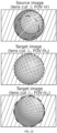
- the method of FIG. 8 is used to process the images acquired by the real source camera where a user command switches the settings of the target camera to alternate between the 30° lens (target 1) and the 70° lens (target 2) ( FIG. 13 ).
- FIG. 8 So far the method of FIG. 8 has been used to select a part of the FoV of the source camera and mimic the video output that would be acquired by a camera with smaller FoV and different lens cut placed in the same 3D location.
- Another possible embodiment or application is to use the disclosed method to shift the DoV of a particular endoscopic camera while maintaining the overall FoV, in which case the principal point in the rendered images moves towards the periphery as the shift in DoV increases ( FIG. 14 ).
- the disclosed methods of FIG. 8 and FIG. 11 are executed in a system that is connected to the source camera, where the distortion ⁇ , image diameter d ⁇ , and FoV ⁇ of the target camera are set with the same values as the source camera, and where the angular shift ⁇ in the DoV is commanded by the user that can freely move it both upwards or downwards ( FIG. 14 ).
- the disclosed system can also be used to implement what is referred to as directional zoom, in which case the angular shift ⁇ is adjusted such that the principal point in the rendered image becomes overlaid with a region of interest (ROI) and the distortion ⁇ is increased to magnify the ROI while maintaining the FoV and all visual contents in the image ( FIG. 15 ).
- the magnification of the ROI can also be accomplished by maintaining the distortion and increasing the focal length f ⁇ in which case the FoV decreases and some image contents will be lost.
- the disclosed methods of the schemes of FIG. 8 and FIG. 11 can be used to process a discrete set of images for the purpose of rendering images of virtual target cameras with different, known calibrations and/or lens cut angles to be used as input to train and/or test machine learning or deep learning based algorithms for automatic learning to identify and estimate different camera and/or lens characteristics, including, but not limited to, identification of the lens cut, estimation of the calibration parameters, learning to generate virtual images with different lens cuts.
- the disclosed methods can also be applied to other types of imagery such as fundus images in ophthalmology.
- the method that is disclosed for selecting the focal length and position of principal point in the target image is not limited to endoscopy applications and can be employed in the warping of generic images and video.
- One possible embodiment is the use of the method in systems of visual surveillance that implement electronic pan-and-tilt in images and videos acquired by a fish-eye camera.
- FIG. 16 is a diagrammatic view of an illustrative computing system that includes a general purpose computing system environment 1200, such as a desktop computer, laptop, smartphone, tablet, or any other such device having the ability to execute instructions, such as those stored within a non-transient, computer-readable medium.
- a general purpose computing system environment 1200 such as a desktop computer, laptop, smartphone, tablet, or any other such device having the ability to execute instructions, such as those stored within a non-transient, computer-readable medium.
- a general purpose computing system environment 1200 such as a desktop computer, laptop, smartphone, tablet, or any other such device having the ability to execute instructions, such as those stored within a non-transient, computer-readable medium.
- a general purpose computing system environment 1200 such as a desktop computer, laptop, smartphone, tablet, or any other such device having the ability to execute instructions, such as those stored within a non-transient, computer-readable medium.
- computing system environment 1200 may find use for the processing, methods, and computing steps of this disclosure.
- computing system environment 1200 typically includes at least one processing unit 1202 and at least one memory 1204, which may be linked via a bus 1206.
- memory 1204 may be volatile (such as RAM 1210), non-volatile (such as ROM 1208, flash memory, etc.) or some combination of the two.
- Computing system environment 1200 may have additional features and/or functionality.
- computing system environment 1200 may also include additional storage (removable and/or non-removable) including, but not limited to, magnetic or optical disks, tape drives and/or flash drives.
- Such additional memory devices may be made accessible to the computing system environment 1200 by means of, for example, a hard disk drive interface 1212, a magnetic disk drive interface 1214, and/or an optical disk drive interface 1216.
- these devices which would be linked to the system bus 1206, respectively, allow for reading from and writing to a hard disk 1218, reading from or writing to a removable magnetic disk 1220, and/or for reading from or writing to a removable optical disk 1222, such as a CD/DVD ROM or other optical media.
- the drive interfaces and their associated computer-readable media allow for the nonvolatile storage of computer readable instructions, data structures, program modules and other data for the computing system environment 1200.
- Computer readable media that can store data may be used for this same purpose.
- Examples of such media devices include, but are not limited to, magnetic cassettes, flash memory cards, digital videodisks, Bernoulli cartridges, random access memories, nano-drives, memory sticks, other read/write and/or read-only memories and/or any other method or technology for storage of information such as computer readable instructions, data structures, program modules or other data. Any such computer storage media may be part of computing system environment 1200.
- a number of program modules may be stored in one or more of the memory/media devices.
- a basic input/output system (BIOS) 1224 containing the basic routines that help to transfer information between elements within the computing system environment 1200, such as during start-up, may be stored in ROM 1208.
- BIOS basic input/output system
- RAM 1210, hard drive 1218, and/or peripheral memory devices may be used to store computer executable instructions comprising an operating system 1226, one or more applications programs 1228 (such as an application that performs the methods and processes of this disclosure), other program modules 1230, and/or program data 1232.
- computer-executable instructions may be downloaded to the computing environment 1200 as needed, for example, via a network connection.
- An end-user may enter commands and information into the computing system environment 1200 through input devices such as a keyboard 1234 and/or a pointing device 1236. While not illustrated, other input devices may include a microphone, a joystick, a game pad, a scanner, etc. These and other input devices would typically be connected to the processing unit 1202 by means of a peripheral interface 1238 which, in turn, would be coupled to bus 1206. Input devices may be directly or indirectly connected to processor 1202 via interfaces such as, for example, a parallel port, game port, firewire, or a universal serial bus (USB).
- USB universal serial bus
- a monitor 1240 or other type of display device may also be connected to bus 1206 via an interface, such as via video adapter 1242.
- the computing system environment 1200 may also include other peripheral output devices, not shown, such as speakers and printers.
- the computing system environment 1200 may also utilize logical connections to one or more computing system environments. Communications between the computing system environment 1200 and the remote computing system environment may be exchanged via a further processing device, such a network router 1252, that is responsible for network routing. Communications with the network router 1252 may be performed via a network interface component 1254.
- a networked environment e.g., the Internet, World Wide Web, LAN, or other like type of wired or wireless network
- program modules depicted relative to the computing system environment 1200, or portions thereof may be stored in the memory storage device(s) of the computing system environment 1200.
- the computing system environment 1200 may also include localization hardware 1256 for determining a location of the computing system environment 1200.
- the localization hardware 1256 may include, for example only, a GPS antenna, an RFID chip or reader, a Wi-Fi antenna, or other computing hardware that may be used to capture or transmit signals that may be used to determine the location of the computing system environment 1200.
- the azimuth ⁇ 0 is referenced by a particular notch position P
- the source image I i is processed to detect the boundary with center C i and notch position P i
- the line n i is defined by points O i and P i
- the region that contains meaningful image contents can take any desired geometric shape, such as, but not limited to, a conic shape, a rectangular shape, an hexagonal shape or any other polygonal shape.
- point Q is determined on-the fly using the detection of points P i and/or C i in successive frames, in which case it does not have to be known or determined a priori.
- line n i is alternatively defined by points O i and Q or O i and C i .
- the position of the principal point is given in a normalized reference frame attached to the circular boundary, in which case the computation of its pixel location O i at every frame time instant i can be accomplished without having to explicitly know the rotation center Q and angular displacement in azimuth ⁇ i .
- the source camera is equipped with an optical encoder, or any other sensing device, that measures the rotation of the scope with respect to the camera-head and estimates the angular displacement in azimuth ⁇ i of step (i).
- the principal point O is coincident with the rotation center Q, in which case the camera model of the source camera does not have to be updated at every frame time instant as in step (ii).
- the distortion of the target camera ⁇ is set to zero in order for the rendered image Î i to be distortion free.
- the rendering of target image Î i in step (vi) is performed using any common method for image warping or pixel value interpolation including, but not limited to, interpolation by nearest neighbors, bilinear interpolation or bicubic interpolation.
- step (vi) the focal length f ⁇ and principal point ⁇ i are such that the rendered image has no empty region and the FoV of the target camera is the specified value ⁇
- the parameters of the target camera can be arbitrary, be predefined to accomplish a certain purpose, be equal to the calibration of a particular real camera equipped with a particular real endoscope with cut angle ⁇ , be chosen by the user at the start of the procedure, or vary during operation according to particular events or user commands.
- the method is used in a system connected to a source camera for the purpose of empowering the user with the possibility of electronically switching between two virtual target cameras with lens cuts and FoVs of ⁇ 1 , ⁇ 1 and ⁇ 2 , ⁇ 2 .
- both the distortion ⁇ and the angular shift ⁇ are set to zero, in which case the system will correct the radial distortion in the source image.
- the distortion ⁇ is set to zero for the target image to be rendered with no radial distortion independently of the chosen angular shift ⁇ .
- the angular shift ⁇ is chosen such that the principal point is placed in a region of interest in the target image and the radial distortion parameter ⁇ is increased to magnify this region of interest while maintaining the FoV of the target camera and all contents visible.
- the source and/or target cameras have radial distortion described by any of the models known in the literature, including, but not limited to, learning-based models, Brown's polynomial model, the rational model, the fish-eye model, or the division model.
- the boundary with center C i and the notch P i are detected using a generic conic detection method, using machine learning or deep learning techniques, or any other image processing technique.
- multiple notch positions are detected and a particular notch of these multiple notches is used for determining the angular displacement in azimuth ⁇ i as the angle defined by points P i , Q, P.
- the Field-of-View ⁇ and the distortion ⁇ of the virtual target camera take the same values as the source camera's, but the lens cut ⁇ is set by the user at every frame time instant.
- the Field-of-View ⁇ of the virtual target camera takes the same value as the source camera's, but the lens cut ⁇ and the distortion ⁇ is set by the user at every frame time instant.
- the Field-of-View ⁇ and the lens cut ⁇ of the virtual target camera take the same values as the source camera's, but the distortion ⁇ is set by the user at every frame time instant to produce a zoom in or zoom out effect that does not change the FoV.
- the Field-of-View ⁇ of the virtual target camera takes the same value as the source camera's, but the lens cut ⁇ and the distortion ⁇ are set by the user at every frame time instant to adapt the DoV and produce a zoom in or zoom out effect that does not change the FoV.
- the Field-of-View ⁇ of the virtual target camera takes the same value as the source camera's, but the lens cut ⁇ and the focal length f ⁇ are set by the user at every frame time instant, in which case the variable to solve for is not the focal length f ⁇ but distortion ⁇ to produce a zoom in or zoom out effect that does not change the FoV.
Landscapes
- Engineering & Computer Science (AREA)
- Health & Medical Sciences (AREA)
- Life Sciences & Earth Sciences (AREA)
- Physics & Mathematics (AREA)
- Surgery (AREA)
- Medical Informatics (AREA)
- Optics & Photonics (AREA)
- Veterinary Medicine (AREA)
- Molecular Biology (AREA)
- Public Health (AREA)
- General Health & Medical Sciences (AREA)
- Biophysics (AREA)
- Nuclear Medicine, Radiotherapy & Molecular Imaging (AREA)
- Animal Behavior & Ethology (AREA)
- Pathology (AREA)
- Radiology & Medical Imaging (AREA)
- Heart & Thoracic Surgery (AREA)
- Biomedical Technology (AREA)
- Theoretical Computer Science (AREA)
- General Physics & Mathematics (AREA)
- Signal Processing (AREA)
- Computer Vision & Pattern Recognition (AREA)
- Computing Systems (AREA)
- Computer Graphics (AREA)
- Geometry (AREA)
- Artificial Intelligence (AREA)
- Evolutionary Computation (AREA)
- Multimedia (AREA)
- Astronomy & Astrophysics (AREA)
- Endoscopes (AREA)
- Instruments For Viewing The Inside Of Hollow Bodies (AREA)
- Image Processing (AREA)
Claims (15)
- Computerimplementiertes Verfahren zum Rendern eines Zielbildes Îi einer virtuellen Zielkamera auf der Basis eines von einer realen Quellkamera aufgenommenen Quellbildes Ii, wobei die Quellkamera einen Kamerakopf und ein starres Endoskop mit einem Linsenschnitt β umfasst, wobei der Linsenschnitt der Winkel zwischen der optischen und der mechanischen Achse des Endoskops ist, das sich im Azimut um eine mechanische Achse dreht, die das Bild in einem Punkt Q schneidet, für den die Brennweite f, die radiale Verzerrung ξ und der Hauptpunkt O bei einem bestimmten Azimut α0 bekannt sind, wobei das Verfahren Folgendes umfasst:Finden einer Position des Hauptpunkts Oi im Quellbild Ii mit Azimut αi durch Drehen von O um Q um eine Winkelverschiebung im Azimut δi = αi - α0;Aktualisieren eines Kameramodells cs der Quellkamera, das Punkte x in einem kanonischen Bild in Punkte u in einem Pixelbild gemäß der Brennweite f, der radialen Verzerrung ξ und der Position des Hauptpunkts Oi abbildet;Bestimmen einer 3D-Position einer vertikalen Ebene Πi, die die mechanische Achse und die optische Achse der Quellkamera enthält, durch Auffinden und Rückprojizieren einer Linie ni in den 3D-Raum, wobei Πi das Quellbild Ii schneidet;Definieren einer 3D-Bewegung m zwischen Ziel- und Quellkamera als eine Drehung um einen Winkel γ = β̂ - β um eine Richtung
n i , die normal zur vertikalen Ebene Πi ist, so dass x = m(x̂; γ,n i), wobei x̂ ein Punkt im kanonischen Bild der Zielkamera und der Linsenschnitt der Zielkamera ist;Berechnen einer Brennweite f̂ und einer Position des Hauptpunkts Ôi für die Zielkamera und Ableiten eines Kameramodells ct, das die Punkte x̂ im kanonischen Bild des Zielbildes gemäß der Brennweite f̂ und der Position des Hauptpunktes Ôi in Punkte û in einem Pixelbild des Zielbildes abbildet; undErzeugen des Zielbildes Îi durch Abbilden mehrerer Pixel û in Îi auf einen Punkt u im Quellbild Ii mit einer Abbildungsfunktion w, die eine Zusammensetzung des Kameramodells cs der Quellkamera, der 3D-Bewegung m und einer Inversen eines Kameramodells ct der Zielkamera ist. - Verfahren nach Anspruch 1, wobei der Azimut α0 einer ersten Kerbenposition P entspricht, wobei das Verfahren ferner Folgendes umfasst:Verarbeiten des Quellbildes Ii, um eine Grenze mit einem Mittelpunkt Ci und einer zweiten Kerbenposition Pi zu erfassen;wobei das Drehen von O um Q um eine Winkelverschiebung im Azimut das Schätzen der Winkelverschiebung im Azimut gemäß der ersten Kerbenposition P, der zweiten Kerbenposition Pi und dem Punkt Q umfasst;wobei die Linie ni durch die Punkte Oi und Pi definiert ist.
- Verfahren nach Anspruch 2, das ferner das Verarbeiten des gerenderten Zielbildes Îi umfasst, um einen schwarzen Rahmen zu erzeugen, der eine Bildregion mit Mittelpunkt Ĉ und Durchmesser d̂ definiert, und um eine Kerbe zu erzeugen, indem eine visuelle Markierung an Punkt
- Verfahren nach Anspruch 3, wobei die Bildregion eines von einer Kreisform, einer Kegelform, einer Rechteckform, einer Sechseckform und einer anderen polygonalen Form hat.
- Verfahren nach Anspruch 2, wobei das Quellbild Ii zwei oder mehr Quellbildrahmen umfasst, wobei der Punkt Q durch Erkennen von Punkt Pi und/oder Ci in aufeinanderfolgenden der zwei oder mehr Rahmen bestimmt wird.
- Verfahren nach Anspruch 2, wobei die Verarbeitung des Quellbildes Ii zum Erkennen einer Grenze mit einem Mittelpunkt Ci und einer zweiten Kerbenposition Pi das Erkennen mehrerer zweiter Kerbenpositionen Pi umfasst, wobei eine der mehreren zweiten Kerbenpositionen zum Bestimmen der Winkelverschiebung im Azimut δi verwendet wird.
- Verfahren nach Anspruch 1, wobei der Azimut α0 einer ersten Kerbenposition P entspricht, wobei das Verfahren ferner Folgendes umfasst:Verarbeiten des Quellbildes Ii, um eine Grenze mit einem Mittelpunkt Ci und einer zweiten Kerbenposition Pi zu erfassen;wobei das Drehen von O um Q um eine Winkelverschiebung im Azimut das Schätzen der Winkelverschiebung im Azimut gemäß der ersten Kerbenposition P, der zweiten Kerbenposition Pi und dem Punkt Q umfasst;wobei die Linie ni definiert ist durch:Punkte Oi und Q; oderPunkte Oi und Ci.
- Verfahren nach Anspruch 1, wobei die Position des Hauptpunkts in einem normalisierten Referenzrahmen angegeben ist, der in dem Endoskop angeordnet oder daran angebracht ist.
- Verfahren nach Anspruch 1, wobei die Quellkamera mit einem Sensor ausgestattet ist, der die Drehung des Endoskops in Bezug auf den Kamerakopf misst und die Winkelverschiebung im Azimut δi schätzt.
- Verfahren nach Anspruch 1, wobei der Hauptpunkt O mit dem Drehmittelpunkt Q zusammenfällt.
- Verfahren nach Anspruch 1, wobei eine Verzerrung der Zielkamera ξ̂ auf Null gesetzt wird.
- Verfahren nach Anspruch 1, wobei das Erzeugen des Zielbildes Îi mittels einer Bildverzerrung oder Pixelwertinterpolation durchgeführt wird, die eines oder mehrere von Interpolation durch nächste Nachbarn, bilinearer Interpolation und bikubischer Interpolation umfasst.
- Verfahren nach Anspruch 1, wobei der Hauptpunkt Ôi mit einem Mittelpunkt C einer Grenze des virtuellen Bildes in Übereinstimmung gebracht wird und das Berechnen der Brennweite f̂ das Lösen von Φ(f̂, ξ̂, Θ̂/2, d̂/2) = 0 umfasst, wobei Φ ein mathematischer Ausdruck ist, der Brennweite, radiale Verzerrung, Bildabstand und Winkel zwischen Rückprojektionsstrahlen in Beziehung setzt.
- Verfahren nach Anspruch 1, wobei der Hauptpunkt Ô i mit einem Mittelpunkt Ĉ einer Grenze des virtuellen Bildes in Übereinstimmung gebracht wird, wobei das Verfahren Folgendes umfasst:Transformieren eines Ursprungs [0, 0]T des Quellbildes durch eine Funktion g, die die Zusammensetzung des Kameramodells cs und der Bewegung m ist, um eine Position
O i im Quellbild zu finden, die auf den Hauptpunkt Ô i abgebildet ist;Bestimmen eines begrenzenden BetrachtungswinkelsΨ i zwischen den Rückprojektionsstrahlen vonO i und einem Punkt in der kreisförmigen Begrenzung, derO i am nächsten liegt;Reduzieren, wennΨ i<Θ̂/2, des Kamerasichtfeldes auf 2Ψ i und Erhalten des Wertes von f̂ durch Lösen der Gleichung Φ(f̂, ξ̂,Ψ i, d̂/2) = 0, wobei Φ ein mathematischer Ausdruck ist, der Brennweite, radiale Verzerrung, Bildabstand und Winkel zwischen Rückprojektionsstrahlen in Beziehung setzt;Erhalten, wennΨ i >= Θ̂/2, des Wertes von f̂ durch Lösen der Gleichung Φ(f̂, ξ̂, Θ̂/2, d̂/2) = 0, wobei Φ ein mathematischer Ausdruck ist, der Brennweite, radiale Verzerrung, Bildabstand und Winkel zwischen Rückprojektionsstrahlen in Beziehung setzt, wobei alle diese Parameter voneinander abhängen. - Verfahren nach Anspruch 1, das ferner Folgendes umfasst:Transformieren eines Ursprungs [0, 0]T des Quellbildes durch eine Funktion g, die die Zusammensetzung des Kameramodells cs und der Bewegung m ist, um eine Position
O i im Quellbild zu finden, die auf den Hauptpunkt Ô i abgebildet ist;Bestimmen eines begrenzenden BetrachtungswinkelsΨ i zwischen den Rückprojektionsstrahlen vonO i und einem Punkt in der kreisförmigen Begrenzung, derO i am nächsten liegt;Lösen, wennΨ i < Θ̂/2, des folgenden Gleichungssystems in Bezug auf die Brennweite f̂ und λ: wenn
wennΨ i >= Θ̂/2, Setzen von Ôi = C und Bestimmen von f̂ durch Lösen von Φ(f̂, ξ̂, Θ̂/2, d̂/2) = 0, wobei Φ der mathematische Ausdruck ist, der Brennweite, radiale Verzerrung, Bildabstand und Winkel zwischen Rückprojektionsstrahlen in Beziehung setzt, die alle voneinander abhängige Parameter sind.
Applications Claiming Priority (3)
| Application Number | Priority Date | Filing Date | Title |
|---|---|---|---|
| US201962911950P | 2019-10-07 | 2019-10-07 | |
| US201962911986P | 2019-10-07 | 2019-10-07 | |
| PCT/US2020/054640 WO2021071991A1 (en) | 2019-10-07 | 2020-10-07 | Systems and methods for changing the direction of view during video guided clinical procedures using real-time image processing |
Publications (3)
| Publication Number | Publication Date |
|---|---|
| EP4041048A1 EP4041048A1 (de) | 2022-08-17 |
| EP4041048A4 EP4041048A4 (de) | 2023-11-15 |
| EP4041048B1 true EP4041048B1 (de) | 2025-01-01 |
Family
ID=75436886
Family Applications (2)
| Application Number | Title | Priority Date | Filing Date |
|---|---|---|---|
| EP20874325.2A Active EP4041048B1 (de) | 2019-10-07 | 2020-10-07 | Systeme und verfahren zur änderung der blickrichtung bei videogesteuerten klinischen verfahren mittels echtzeit-bildverarbeitung |
| EP20875045.5A Pending EP4041049A4 (de) | 2019-10-07 | 2020-10-07 | Systeme und verfahren zur charakterisierung eines endoskops und automatische kalibrierung eines endoskopischen kamerasystems |
Family Applications After (1)
| Application Number | Title | Priority Date | Filing Date |
|---|---|---|---|
| EP20875045.5A Pending EP4041049A4 (de) | 2019-10-07 | 2020-10-07 | Systeme und verfahren zur charakterisierung eines endoskops und automatische kalibrierung eines endoskopischen kamerasystems |
Country Status (6)
| Country | Link |
|---|---|
| US (4) | US12220104B2 (de) |
| EP (2) | EP4041048B1 (de) |
| JP (2) | JP7727622B2 (de) |
| CN (2) | CN114727744B (de) |
| AU (3) | AU2020362216B2 (de) |
| WO (2) | WO2021071988A1 (de) |
Families Citing this family (17)
| Publication number | Priority date | Publication date | Assignee | Title |
|---|---|---|---|---|
| WO2020086911A1 (en) | 2018-10-26 | 2020-04-30 | Intuitive Surgical Operations, Inc. | Mixed reality systems and methods for indicating an extent of a field of view of an imaging device |
| US12008721B2 (en) * | 2018-10-26 | 2024-06-11 | Intuitive Surgical Operations, Inc. | Mixed reality systems and methods for indicating an extent of a field of view of an imaging device |
| EP4041048B1 (de) | 2019-10-07 | 2025-01-01 | S&N Orion Prime, S.A. | Systeme und verfahren zur änderung der blickrichtung bei videogesteuerten klinischen verfahren mittels echtzeit-bildverarbeitung |
| EP4107748B1 (de) | 2020-02-20 | 2026-04-08 | Smith & Nephew, Inc. | Verfahren zur arthroskopischen videoanalyse und vorrichtungen dafür |
| WO2021203077A1 (en) | 2020-04-03 | 2021-10-07 | Smith & Nephew, Inc. | Methods for arthroscopic surgery video segmentation and devices therefor |
| WO2021203082A1 (en) | 2020-04-03 | 2021-10-07 | Smith & Nephew, Inc. | User interface for digital markers in arthroscopy |
| US12236624B2 (en) | 2020-09-23 | 2025-02-25 | Smith & Nephew, Inc. | Optical caliper for 3-D endoscopic imaging and measurement |
| CN114913236A (zh) * | 2021-02-09 | 2022-08-16 | 深圳市汇顶科技股份有限公司 | 相机标定方法、装置及电子设备 |
| EP4295746B1 (de) * | 2021-02-22 | 2026-04-08 | Panasonic Intellectual Property Management Co., Ltd. | Intraorales kamerasystem und bildanzeigeverfahren |
| WO2022251814A2 (en) | 2021-05-24 | 2022-12-01 | Stryker Corporation | Systems and methods for generating three-dimensional measurements using endoscopic video data |
| CN115393221B (zh) * | 2022-08-29 | 2023-06-20 | 眉山市人民医院 | 适用于输尿管软镜末端的探镜角度校准方法、终端及介质 |
| CN115590456B (zh) * | 2022-09-29 | 2026-01-02 | 上海交通大学 | 转动式实时全景耳科用内窥镜 |
| US12591997B2 (en) * | 2023-01-25 | 2026-03-31 | Auros Technology, Inc. | Arrangement device and method |
| CN117392243B (zh) * | 2023-12-13 | 2024-02-06 | 山东科技大学 | 基于图像处理的编码器安装位置检测方法及系统 |
| CN117796745B (zh) * | 2024-02-29 | 2024-05-03 | 四川大学 | 一种估计消化内镜镜头进退距离的方法 |
| CN118747881B (zh) * | 2024-08-30 | 2025-01-28 | 纽劢科技(上海)有限公司 | 一种基于全fov标注方式的真值评测方法及装置 |
| FR3166464A1 (fr) * | 2024-09-19 | 2026-03-20 | Surgar | Système et procédé d’étalonnage dynamique d’une caméra endoscopique |
Family Cites Families (41)
| Publication number | Priority date | Publication date | Assignee | Title |
|---|---|---|---|---|
| US5313306A (en) | 1991-05-13 | 1994-05-17 | Telerobotics International, Inc. | Omniview motionless camera endoscopy system |
| US5417210A (en) * | 1992-05-27 | 1995-05-23 | International Business Machines Corporation | System and method for augmentation of endoscopic surgery |
| US7344494B2 (en) | 2004-02-09 | 2008-03-18 | Karl Storz Development Corp. | Endoscope with variable direction of view module |
| US9615772B2 (en) * | 2004-02-20 | 2017-04-11 | Karl Storz Imaging, Inc. | Global endoscopic viewing indicator |
| JP4631048B2 (ja) * | 2005-02-14 | 2011-02-16 | 国立大学法人岩手大学 | 撮像装置及び撮像系パラメータの校正方法 |
| US9526587B2 (en) * | 2008-12-31 | 2016-12-27 | Intuitive Surgical Operations, Inc. | Fiducial marker design and detection for locating surgical instrument in images |
| US20070161854A1 (en) * | 2005-10-26 | 2007-07-12 | Moshe Alamaro | System and method for endoscopic measurement and mapping of internal organs, tumors and other objects |
| GB0605817D0 (en) | 2006-03-23 | 2006-05-03 | Imp Innovations Ltd | Reconstruction of anterior cruciate ligaments |
| US20070236514A1 (en) * | 2006-03-29 | 2007-10-11 | Bracco Imaging Spa | Methods and Apparatuses for Stereoscopic Image Guided Surgical Navigation |
| US8052598B2 (en) * | 2006-10-12 | 2011-11-08 | General Electric Company | Systems and methods for calibrating an endoscope |
| US7892165B2 (en) * | 2006-10-23 | 2011-02-22 | Hoya Corporation | Camera calibration for endoscope navigation system |
| US8864652B2 (en) | 2008-06-27 | 2014-10-21 | Intuitive Surgical Operations, Inc. | Medical robotic system providing computer generated auxiliary views of a camera instrument for controlling the positioning and orienting of its tip |
| US10092169B2 (en) | 2008-07-08 | 2018-10-09 | Karl Storz Imaging, Inc. | Solid state variable direction of view endoscope |
| US8223193B2 (en) | 2009-03-31 | 2012-07-17 | Intuitive Surgical Operations, Inc. | Targets, fixtures, and workflows for calibrating an endoscopic camera |
| DE102010040992A1 (de) | 2010-09-17 | 2012-03-22 | Henke-Sass, Wolf Gmbh | Endoskop mit variabler Blickrichtung |
| CN103827917B (zh) * | 2011-07-25 | 2017-06-09 | 科英布拉大学 | 用于使用棋盘图案的一幅或多幅图像的自动相机校准的方法和装置 |
| EP2895124B1 (de) | 2012-09-12 | 2020-11-04 | National University of Singapore | Vorrichtung zur einsetzung eines implantats |
| SG11201502488QA (en) | 2012-09-30 | 2015-05-28 | Univ Singapore | Bio-absorbable medicament-eluting ventilation tube |
| US20150238276A1 (en) * | 2012-09-30 | 2015-08-27 | M.S.T. Medical Surgery Technologies Ltd. | Device and method for assisting laparoscopic surgery - directing and maneuvering articulating tool |
| DE102012111290A1 (de) | 2012-11-22 | 2014-05-22 | Karl Storz Gmbh & Co. Kg | Ein Endoskop mit einstellbarer Blickrichtung |
| DE102013220945A1 (de) | 2013-10-16 | 2015-04-30 | Olympus Winter & Ibe Gmbh | Endoskop mit einstellbarer Blickrichtung |
| WO2015064521A1 (ja) * | 2013-10-30 | 2015-05-07 | オリンパスメディカルシステムズ株式会社 | 撮像装置 |
| US11116383B2 (en) * | 2014-04-02 | 2021-09-14 | Asensus Surgical Europe S.à.R.L. | Articulated structured light based-laparoscope |
| US10499996B2 (en) | 2015-03-26 | 2019-12-10 | Universidade De Coimbra | Methods and systems for computer-aided surgery using intra-operative video acquired by a free moving camera |
| WO2017027638A1 (en) * | 2015-08-10 | 2017-02-16 | The Board Of Trustees Of The Leland Stanford Junior University | 3d reconstruction and registration of endoscopic data |
| EP3130276B8 (de) | 2015-08-12 | 2020-02-26 | TransEnterix Europe Sàrl | Endoskop mit weitwinkellinse und einstellbarer ansicht |
| US10176554B2 (en) * | 2015-10-05 | 2019-01-08 | Google Llc | Camera calibration using synthetic images |
| JP6704413B2 (ja) * | 2015-12-17 | 2020-06-03 | オリンパス株式会社 | 内視鏡用光学アダプタ |
| WO2018232322A1 (en) * | 2017-06-15 | 2018-12-20 | Children's National Medical Center | System, apparatus and method for calibrating oblique-viewing rigid endoscope |
| WO2019054946A1 (en) | 2017-09-13 | 2019-03-21 | National University Of Singapore | METHOD AND DEVICES FOR INCLUDING AND INSERTING A VENTILATION TUBE |
| CN108938086A (zh) * | 2018-06-08 | 2018-12-07 | 艾瑞迈迪医疗科技(北京)有限公司 | 内窥镜畸变矫正方法及手术导航设备 |
| EP4647034A3 (de) * | 2018-08-24 | 2025-12-10 | Intuitive Surgical Operations, Inc. | Kameraexterne kalibrierungsparameter für eine bilderfassungsvorrichtung |
| CN110335318B (zh) * | 2019-04-28 | 2022-02-11 | 安翰科技(武汉)股份有限公司 | 一种基于摄像系统的消化道内物体测量方法 |
| EP4041048B1 (de) * | 2019-10-07 | 2025-01-01 | S&N Orion Prime, S.A. | Systeme und verfahren zur änderung der blickrichtung bei videogesteuerten klinischen verfahren mittels echtzeit-bildverarbeitung |
| EP4107748B1 (de) | 2020-02-20 | 2026-04-08 | Smith & Nephew, Inc. | Verfahren zur arthroskopischen videoanalyse und vorrichtungen dafür |
| WO2021203077A1 (en) | 2020-04-03 | 2021-10-07 | Smith & Nephew, Inc. | Methods for arthroscopic surgery video segmentation and devices therefor |
| WO2021203082A1 (en) | 2020-04-03 | 2021-10-07 | Smith & Nephew, Inc. | User interface for digital markers in arthroscopy |
| US12343218B2 (en) | 2020-06-18 | 2025-07-01 | Smith & Nephew, Inc. | Methods for autoregistration of arthroscopic video images to preoperative models and devices thereof |
| US20230225822A1 (en) | 2020-07-02 | 2023-07-20 | Smith & Nephew, Inc. | Optical Tracking of Objects in Arthroscopic Surgery |
| US20230210542A1 (en) | 2020-07-02 | 2023-07-06 | Smith & Nephew, Inc. | Methods and Systems for Treating Femoroacetabular Impingement |
| US12502222B2 (en) | 2021-01-25 | 2025-12-23 | Smith & Nephew, Inc. | Systems and methods for fusing arthroscopic video data |
-
2020
- 2020-10-07 EP EP20874325.2A patent/EP4041048B1/de active Active
- 2020-10-07 JP JP2022520932A patent/JP7727622B2/ja active Active
- 2020-10-07 US US17/762,205 patent/US12220104B2/en active Active
- 2020-10-07 CN CN202080068251.7A patent/CN114727744B/zh active Active
- 2020-10-07 JP JP2022520683A patent/JP7604473B2/ja active Active
- 2020-10-07 CN CN202080068842.4A patent/CN114630611B/zh active Active
- 2020-10-07 EP EP20875045.5A patent/EP4041049A4/de active Pending
- 2020-10-07 AU AU2020362216A patent/AU2020362216B2/en active Active
- 2020-10-07 US US17/762,179 patent/US12178401B2/en active Active
- 2020-10-07 AU AU2020362217A patent/AU2020362217B2/en active Active
- 2020-10-07 WO PCT/US2020/054636 patent/WO2021071988A1/en not_active Ceased
- 2020-10-07 WO PCT/US2020/054640 patent/WO2021071991A1/en not_active Ceased
-
2024
- 2024-11-18 US US18/951,043 patent/US12605049B2/en active Active
-
2025
- 2025-01-02 US US19/008,365 patent/US20250134360A1/en active Pending
- 2025-09-25 AU AU2025238014A patent/AU2025238014A1/en active Pending
Also Published As
| Publication number | Publication date |
|---|---|
| US20250089999A1 (en) | 2025-03-20 |
| EP4041048A4 (de) | 2023-11-15 |
| WO2021071991A1 (en) | 2021-04-15 |
| JP7604473B2 (ja) | 2024-12-23 |
| AU2020362217A1 (en) | 2022-04-07 |
| EP4041049A1 (de) | 2022-08-17 |
| AU2020362217B2 (en) | 2025-05-29 |
| JP2023504344A (ja) | 2023-02-03 |
| CN114727744B (zh) | 2026-01-30 |
| JP7727622B2 (ja) | 2025-08-21 |
| AU2020362216B2 (en) | 2025-06-26 |
| US20220383588A1 (en) | 2022-12-01 |
| EP4041048A1 (de) | 2022-08-17 |
| CN114727744A (zh) | 2022-07-08 |
| CN114630611A (zh) | 2022-06-14 |
| US20220392110A1 (en) | 2022-12-08 |
| US12220104B2 (en) | 2025-02-11 |
| US20250134360A1 (en) | 2025-05-01 |
| WO2021071988A1 (en) | 2021-04-15 |
| EP4041049A4 (de) | 2024-01-10 |
| AU2020362216A1 (en) | 2022-04-14 |
| CN114630611B (zh) | 2026-03-31 |
| US12178401B2 (en) | 2024-12-31 |
| JP2022550913A (ja) | 2022-12-05 |
| AU2025238014A1 (en) | 2025-10-16 |
| US12605049B2 (en) | 2026-04-21 |
Similar Documents
| Publication | Publication Date | Title |
|---|---|---|
| EP4041048B1 (de) | Systeme und verfahren zur änderung der blickrichtung bei videogesteuerten klinischen verfahren mittels echtzeit-bildverarbeitung | |
| JP7280188B2 (ja) | 医療用拡大高解像度撮像方法及び撮像システム | |
| JP7460631B2 (ja) | デュアル画像センサを有する内視鏡 | |
| US12290235B2 (en) | Wireless laparoscopic device with gimballed camera | |
| US8911358B2 (en) | Endoscopic vision system | |
| EP2143374B1 (de) | Festkörperendoskop mit variabler Sichtrichtung | |
| US20140336461A1 (en) | Surgical structured light system | |
| AU2022205690A9 (en) | Registration degradation correction for surgical navigation procedures | |
| JPWO2016199273A1 (ja) | 内視鏡装置及び内視鏡装置の作動方法 | |
| CN114051387A (zh) | 医学观察系统、控制装置和控制方法 | |
| JP2008532602A (ja) | 外科手術ナビゲーションと顕微鏡による可視化の方法と装置 | |
| WO2020054566A1 (ja) | 医療用観察システム、医療用観察装置及び医療用観察方法 | |
| CN111067468A (zh) | 用于控制内窥镜系统的方法、设备及存储介质 | |
| WO2015046152A1 (ja) | 内視鏡システム | |
| CN116421311A (zh) | 基于术前术中三维网格融合的术中危险区域生成系统 | |
| WO2025088159A1 (en) | Endoscopic systems and methods for imaging an object | |
| EP2031559A1 (de) | Vergrößerte Visualisierung in zweidimensionalen Bildern | |
| JP7549731B2 (ja) | 手術システムおよび手術システムの制御方法 | |
| KR20200132174A (ko) | 증강현실 대장 내시경 시스템 및 이를 이용한 모니터링 방법 | |
| WO2023184526A1 (en) | System and method of real-time stereoscopic visualization based on monocular camera | |
| Hayashibe et al. | Real-time 3D deformation imaging of abdominal organs in laparoscopy | |
| JP2004173973A (ja) | 斜視内視鏡用投影モデルのパラメータ推定方法 |
Legal Events
| Date | Code | Title | Description |
|---|---|---|---|
| STAA | Information on the status of an ep patent application or granted ep patent |
Free format text: STATUS: THE INTERNATIONAL PUBLICATION HAS BEEN MADE |
|
| PUAI | Public reference made under article 153(3) epc to a published international application that has entered the european phase |
Free format text: ORIGINAL CODE: 0009012 |
|
| STAA | Information on the status of an ep patent application or granted ep patent |
Free format text: STATUS: REQUEST FOR EXAMINATION WAS MADE |
|
| 17P | Request for examination filed |
Effective date: 20220428 |
|
| AK | Designated contracting states |
Kind code of ref document: A1 Designated state(s): AL AT BE BG CH CY CZ DE DK EE ES FI FR GB GR HR HU IE IS IT LI LT LU LV MC MK MT NL NO PL PT RO RS SE SI SK SM TR |
|
| DAV | Request for validation of the european patent (deleted) | ||
| DAX | Request for extension of the european patent (deleted) | ||
| A4 | Supplementary search report drawn up and despatched |
Effective date: 20231012 |
|
| RIC1 | Information provided on ipc code assigned before grant |
Ipc: G06T 7/80 20170101ALI20231006BHEP Ipc: G06T 7/73 20170101ALI20231006BHEP Ipc: G06T 7/70 20170101ALI20231006BHEP Ipc: A61B 1/05 20060101ALI20231006BHEP Ipc: A61B 1/04 20060101ALI20231006BHEP Ipc: A61B 1/00 20060101AFI20231006BHEP |
|
| GRAP | Despatch of communication of intention to grant a patent |
Free format text: ORIGINAL CODE: EPIDOSNIGR1 |
|
| STAA | Information on the status of an ep patent application or granted ep patent |
Free format text: STATUS: GRANT OF PATENT IS INTENDED |
|
| INTG | Intention to grant announced |
Effective date: 20240917 |
|
| GRAS | Grant fee paid |
Free format text: ORIGINAL CODE: EPIDOSNIGR3 |
|
| GRAA | (expected) grant |
Free format text: ORIGINAL CODE: 0009210 |
|
| STAA | Information on the status of an ep patent application or granted ep patent |
Free format text: STATUS: THE PATENT HAS BEEN GRANTED |
|
| AK | Designated contracting states |
Kind code of ref document: B1 Designated state(s): AL AT BE BG CH CY CZ DE DK EE ES FI FR GB GR HR HU IE IS IT LI LT LU LV MC MK MT NL NO PL PT RO RS SE SI SK SM TR |
|
| REG | Reference to a national code |
Ref country code: GB Ref legal event code: FG4D |
|
| P01 | Opt-out of the competence of the unified patent court (upc) registered |
Free format text: CASE NUMBER: APP_63788/2024 Effective date: 20241202 |
|
| REG | Reference to a national code |
Ref country code: DE Ref legal event code: R096 Ref document number: 602020044272 Country of ref document: DE |
|
| REG | Reference to a national code |
Ref country code: CH Ref legal event code: EP |
|
| REG | Reference to a national code |
Ref country code: IE Ref legal event code: FG4D |
|
| REG | Reference to a national code |
Ref country code: LT Ref legal event code: MG9D |
|
| REG | Reference to a national code |
Ref country code: NL Ref legal event code: MP Effective date: 20250101 |
|
| REG | Reference to a national code |
Ref country code: AT Ref legal event code: MK05 Ref document number: 1755378 Country of ref document: AT Kind code of ref document: T Effective date: 20250101 |
|
| PG25 | Lapsed in a contracting state [announced via postgrant information from national office to epo] |
Ref country code: NL Free format text: LAPSE BECAUSE OF FAILURE TO SUBMIT A TRANSLATION OF THE DESCRIPTION OR TO PAY THE FEE WITHIN THE PRESCRIBED TIME-LIMIT Effective date: 20250101 |
|
| PG25 | Lapsed in a contracting state [announced via postgrant information from national office to epo] |
Ref country code: FI Free format text: LAPSE BECAUSE OF FAILURE TO SUBMIT A TRANSLATION OF THE DESCRIPTION OR TO PAY THE FEE WITHIN THE PRESCRIBED TIME-LIMIT Effective date: 20250101 |
|
| PG25 | Lapsed in a contracting state [announced via postgrant information from national office to epo] |
Ref country code: PL Free format text: LAPSE BECAUSE OF FAILURE TO SUBMIT A TRANSLATION OF THE DESCRIPTION OR TO PAY THE FEE WITHIN THE PRESCRIBED TIME-LIMIT Effective date: 20250101 |
|
| PG25 | Lapsed in a contracting state [announced via postgrant information from national office to epo] |
Ref country code: ES Free format text: LAPSE BECAUSE OF FAILURE TO SUBMIT A TRANSLATION OF THE DESCRIPTION OR TO PAY THE FEE WITHIN THE PRESCRIBED TIME-LIMIT Effective date: 20250101 |
|
| PG25 | Lapsed in a contracting state [announced via postgrant information from national office to epo] |
Ref country code: IS Free format text: LAPSE BECAUSE OF FAILURE TO SUBMIT A TRANSLATION OF THE DESCRIPTION OR TO PAY THE FEE WITHIN THE PRESCRIBED TIME-LIMIT Effective date: 20250501 Ref country code: NO Free format text: LAPSE BECAUSE OF FAILURE TO SUBMIT A TRANSLATION OF THE DESCRIPTION OR TO PAY THE FEE WITHIN THE PRESCRIBED TIME-LIMIT Effective date: 20250401 |
|
| PG25 | Lapsed in a contracting state [announced via postgrant information from national office to epo] |
Ref country code: HR Free format text: LAPSE BECAUSE OF FAILURE TO SUBMIT A TRANSLATION OF THE DESCRIPTION OR TO PAY THE FEE WITHIN THE PRESCRIBED TIME-LIMIT Effective date: 20250101 |
|
| PG25 | Lapsed in a contracting state [announced via postgrant information from national office to epo] |
Ref country code: LV Free format text: LAPSE BECAUSE OF FAILURE TO SUBMIT A TRANSLATION OF THE DESCRIPTION OR TO PAY THE FEE WITHIN THE PRESCRIBED TIME-LIMIT Effective date: 20250101 Ref country code: PT Free format text: LAPSE BECAUSE OF FAILURE TO SUBMIT A TRANSLATION OF THE DESCRIPTION OR TO PAY THE FEE WITHIN THE PRESCRIBED TIME-LIMIT Effective date: 20250502 |
|
| PG25 | Lapsed in a contracting state [announced via postgrant information from national office to epo] |
Ref country code: BG Free format text: LAPSE BECAUSE OF FAILURE TO SUBMIT A TRANSLATION OF THE DESCRIPTION OR TO PAY THE FEE WITHIN THE PRESCRIBED TIME-LIMIT Effective date: 20250101 |
|
| PG25 | Lapsed in a contracting state [announced via postgrant information from national office to epo] |
Ref country code: AT Free format text: LAPSE BECAUSE OF FAILURE TO SUBMIT A TRANSLATION OF THE DESCRIPTION OR TO PAY THE FEE WITHIN THE PRESCRIBED TIME-LIMIT Effective date: 20250101 |
|
| PG25 | Lapsed in a contracting state [announced via postgrant information from national office to epo] |
Ref country code: CZ Free format text: LAPSE BECAUSE OF FAILURE TO SUBMIT A TRANSLATION OF THE DESCRIPTION OR TO PAY THE FEE WITHIN THE PRESCRIBED TIME-LIMIT Effective date: 20250101 |
|
| PG25 | Lapsed in a contracting state [announced via postgrant information from national office to epo] |
Ref country code: SE Free format text: LAPSE BECAUSE OF FAILURE TO SUBMIT A TRANSLATION OF THE DESCRIPTION OR TO PAY THE FEE WITHIN THE PRESCRIBED TIME-LIMIT Effective date: 20250101 |
|
| REG | Reference to a national code |
Ref country code: DE Ref legal event code: R097 Ref document number: 602020044272 Country of ref document: DE |
|
| PG25 | Lapsed in a contracting state [announced via postgrant information from national office to epo] |
Ref country code: SM Free format text: LAPSE BECAUSE OF FAILURE TO SUBMIT A TRANSLATION OF THE DESCRIPTION OR TO PAY THE FEE WITHIN THE PRESCRIBED TIME-LIMIT Effective date: 20250101 |
|
| PG25 | Lapsed in a contracting state [announced via postgrant information from national office to epo] |
Ref country code: DK Free format text: LAPSE BECAUSE OF FAILURE TO SUBMIT A TRANSLATION OF THE DESCRIPTION OR TO PAY THE FEE WITHIN THE PRESCRIBED TIME-LIMIT Effective date: 20250101 |
|
| PG25 | Lapsed in a contracting state [announced via postgrant information from national office to epo] |
Ref country code: IT Free format text: LAPSE BECAUSE OF FAILURE TO SUBMIT A TRANSLATION OF THE DESCRIPTION OR TO PAY THE FEE WITHIN THE PRESCRIBED TIME-LIMIT Effective date: 20250101 |
|
| PGFP | Annual fee paid to national office [announced via postgrant information from national office to epo] |
Ref country code: GB Payment date: 20250918 Year of fee payment: 6 |
|
| PGFP | Annual fee paid to national office [announced via postgrant information from national office to epo] |
Ref country code: FR Payment date: 20250922 Year of fee payment: 6 |
|
| PG25 | Lapsed in a contracting state [announced via postgrant information from national office to epo] |
Ref country code: EE Free format text: LAPSE BECAUSE OF FAILURE TO SUBMIT A TRANSLATION OF THE DESCRIPTION OR TO PAY THE FEE WITHIN THE PRESCRIBED TIME-LIMIT Effective date: 20250101 |
|
| PG25 | Lapsed in a contracting state [announced via postgrant information from national office to epo] |
Ref country code: RO Free format text: LAPSE BECAUSE OF FAILURE TO SUBMIT A TRANSLATION OF THE DESCRIPTION OR TO PAY THE FEE WITHIN THE PRESCRIBED TIME-LIMIT Effective date: 20250101 |
|
| PG25 | Lapsed in a contracting state [announced via postgrant information from national office to epo] |
Ref country code: SK Free format text: LAPSE BECAUSE OF FAILURE TO SUBMIT A TRANSLATION OF THE DESCRIPTION OR TO PAY THE FEE WITHIN THE PRESCRIBED TIME-LIMIT Effective date: 20250101 |
|
| PLBE | No opposition filed within time limit |
Free format text: ORIGINAL CODE: 0009261 |
|
| STAA | Information on the status of an ep patent application or granted ep patent |
Free format text: STATUS: NO OPPOSITION FILED WITHIN TIME LIMIT |
|
| 26N | No opposition filed |
Effective date: 20251002 |
|
| PGFP | Annual fee paid to national office [announced via postgrant information from national office to epo] |
Ref country code: DE Payment date: 20250916 Year of fee payment: 6 |