EP4041042B1 - Ustensile por ramasser et verser des produits solides et liquides - Google Patents
Ustensile por ramasser et verser des produits solides et liquides Download PDFInfo
- Publication number
- EP4041042B1 EP4041042B1 EP20767595.0A EP20767595A EP4041042B1 EP 4041042 B1 EP4041042 B1 EP 4041042B1 EP 20767595 A EP20767595 A EP 20767595A EP 4041042 B1 EP4041042 B1 EP 4041042B1
- Authority
- EP
- European Patent Office
- Prior art keywords
- utensil
- sheet
- vertex
- edges
- reversibly
- Prior art date
- Legal status (The legal status is an assumption and is not a legal conclusion. Google has not performed a legal analysis and makes no representation as to the accuracy of the status listed.)
- Active
Links
- 239000012265 solid product Substances 0.000 title description 9
- 239000012263 liquid product Substances 0.000 title description 6
- 239000000463 material Substances 0.000 claims description 16
- 238000005304 joining Methods 0.000 claims description 12
- 230000002441 reversible effect Effects 0.000 claims description 6
- 239000004033 plastic Substances 0.000 claims description 5
- 229920003023 plastic Polymers 0.000 claims description 5
- 235000001674 Agaricus brunnescens Nutrition 0.000 claims description 2
- 229910003460 diamond Inorganic materials 0.000 claims description 2
- 239000010432 diamond Substances 0.000 claims description 2
- 229920001821 foam rubber Polymers 0.000 claims description 2
- 239000004814 polyurethane Substances 0.000 claims description 2
- 229920003225 polyurethane elastomer Polymers 0.000 claims description 2
- 238000005452 bending Methods 0.000 description 9
- 239000000428 dust Substances 0.000 description 8
- 239000007788 liquid Substances 0.000 description 7
- 239000008188 pellet Substances 0.000 description 5
- 230000008901 benefit Effects 0.000 description 4
- 238000005520 cutting process Methods 0.000 description 4
- 239000000047 product Substances 0.000 description 3
- 235000009508 confectionery Nutrition 0.000 description 2
- 239000000686 essence Substances 0.000 description 2
- 235000013305 food Nutrition 0.000 description 2
- 239000010985 leather Substances 0.000 description 2
- 238000004519 manufacturing process Methods 0.000 description 2
- 238000000034 method Methods 0.000 description 2
- 239000000203 mixture Substances 0.000 description 2
- 238000004806 packaging method and process Methods 0.000 description 2
- 239000000843 powder Substances 0.000 description 2
- 238000007789 sealing Methods 0.000 description 2
- 239000011343 solid material Substances 0.000 description 2
- 238000003860 storage Methods 0.000 description 2
- 239000002699 waste material Substances 0.000 description 2
- 244000299461 Theobroma cacao Species 0.000 description 1
- 239000011358 absorbing material Substances 0.000 description 1
- 230000001154 acute effect Effects 0.000 description 1
- XAGFODPZIPBFFR-UHFFFAOYSA-N aluminium Chemical compound [Al] XAGFODPZIPBFFR-UHFFFAOYSA-N 0.000 description 1
- 229910052782 aluminium Inorganic materials 0.000 description 1
- 238000004873 anchoring Methods 0.000 description 1
- 238000013459 approach Methods 0.000 description 1
- 230000015572 biosynthetic process Effects 0.000 description 1
- 235000013339 cereals Nutrition 0.000 description 1
- 230000008859 change Effects 0.000 description 1
- 235000019219 chocolate Nutrition 0.000 description 1
- 238000013461 design Methods 0.000 description 1
- 239000010791 domestic waste Substances 0.000 description 1
- 230000003503 early effect Effects 0.000 description 1
- 238000007688 edging Methods 0.000 description 1
- 230000000694 effects Effects 0.000 description 1
- 235000013312 flour Nutrition 0.000 description 1
- 239000008187 granular material Substances 0.000 description 1
- 230000005484 gravity Effects 0.000 description 1
- 239000004615 ingredient Substances 0.000 description 1
- 238000003780 insertion Methods 0.000 description 1
- 230000037431 insertion Effects 0.000 description 1
- 238000009434 installation Methods 0.000 description 1
- 239000004816 latex Substances 0.000 description 1
- 229920000126 latex Polymers 0.000 description 1
- 238000012986 modification Methods 0.000 description 1
- 230000004048 modification Effects 0.000 description 1
- 235000019645 odor Nutrition 0.000 description 1
- 239000011236 particulate material Substances 0.000 description 1
- 239000002304 perfume Substances 0.000 description 1
- 230000008569 process Effects 0.000 description 1
- 238000012545 processing Methods 0.000 description 1
- 230000001681 protective effect Effects 0.000 description 1
- 238000004080 punching Methods 0.000 description 1
- 239000007787 solid Substances 0.000 description 1
- 239000000725 suspension Substances 0.000 description 1
- 238000012546 transfer Methods 0.000 description 1
- 239000002023 wood Substances 0.000 description 1
Images


Classifications
-
- A—HUMAN NECESSITIES
- A47—FURNITURE; DOMESTIC ARTICLES OR APPLIANCES; COFFEE MILLS; SPICE MILLS; SUCTION CLEANERS IN GENERAL
- A47L—DOMESTIC WASHING OR CLEANING; SUCTION CLEANERS IN GENERAL
- A47L13/00—Implements for cleaning floors, carpets, furniture, walls, or wall coverings
- A47L13/10—Scrubbing; Scouring; Cleaning; Polishing
- A47L13/50—Auxiliary implements
- A47L13/52—Dust pans; Crumb trays
-
- A—HUMAN NECESSITIES
- A46—BRUSHWARE
- A46B—BRUSHES
- A46B15/00—Other brushes; Brushes with additional arrangements
- A46B15/0095—Brushes with a feature for storage after use
-
- A—HUMAN NECESSITIES
- A46—BRUSHWARE
- A46B—BRUSHES
- A46B9/00—Arrangements of the bristles in the brush body
- A46B9/005—Arrangements of the bristles in the brush body where the brushing material is not made of bristles, e.g. sponge, rubber or paper
-
- B—PERFORMING OPERATIONS; TRANSPORTING
- B67—OPENING, CLOSING OR CLEANING BOTTLES, JARS OR SIMILAR CONTAINERS; LIQUID HANDLING
- B67C—CLEANING, FILLING WITH LIQUIDS OR SEMILIQUIDS, OR EMPTYING, OF BOTTLES, JARS, CANS, CASKS, BARRELS, OR SIMILAR CONTAINERS, NOT OTHERWISE PROVIDED FOR; FUNNELS
- B67C11/00—Funnels, e.g. for liquids
Definitions
- the present invention is relative to a utensil for collecting and pouring solid or liquid products, and in particular a constructively simple, practical and very versatile utensils adapted both for collecting and pouring solid products in powder or granular form, and for collecting and pouring liquids.
- utensils are available on the market for collecting for example bits of food products or processing waste in general. These utensils are common scoops provided with a collecting brush in which the scoop consists of a handle integral with a collecting portion having a flat bottom and lateral holding walls, the front edge also being tapered to make the collection of the material easier.
- a utensil of this kind is represented by a bailing scoop that also consists of a handle integral with a collecting portion in the shape of an elongate bowl, like a large spoon.
- the scoop is generally used to transfer powders, flours, grains or more generally products in granular form, but also various types of liquids, from one container to another.
- GB-A-946533 discloses an utensil comprising a main body in the shape of a hollow cone of flexible material, the rim of which runs to a point at one place in its circumference so as to form a substantially triangular shaped lip.
- the technical problem at the basis of the present invention is therefore to provide a utensil for collecting and pouring solid or liquid products that is ergonomic, practical, versatile, easy to use, compact and economic to make.
- a first objective of the present invention is therefore a utensil for collecting and pouring solid products, that is easy to assemble because it is provided with a small number of practical and easily assembled elements.
- a second objective is a utensil provided with a modifiable structure that can be quickly adapted to collecting and pouring solid and liquid products.
- a third objective is a utensil having a particular shape that is easily used as a scoop for collecting solid products.
- a further objective is a utensil comprising a support and a packaging conceived so as to make it suitable for accessory functions.
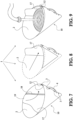
- reference numeral 1 indicates the generality of the exploded-view drawing of a utensil for collecting and pouring solid or liquid products according to the present invention.
- the utensil 1 ( figure 4 ) comprises a main body 10 in the shape of a hollow cone formed by the closing upon itself of a sheet of foldable material 2 along two adjoining edges, means 3 for reversibly joining said two edges, grasping means 4 for handling said utensil, means 5 for reversibly closing the vertex of the main body.
- the sheet 2 ( figure 1 ) has generally a diamond shape in a top view with four vertexes, a first vertex 6 opposite a second vertex 7 along a larger diameter D1, a third vertex 8 opposite a fourth vertex 9 along a smaller diameter D2.
- each of said first 6 and second 7 vertices is rounded and acute.
- the third 8 and fourth vertex 9 are instead preferably with an obtuse or rounded angle.
- the curve of the third vertex extends further with respect to the curve of the fourth vertex.
- an appendage 5 that forms the above-mentioned reversible closing means of the vertex of the main body 10, when the sheet 2 is folded as shown in figures 2 to 5 .
- the appendage 5 can be provided with notches 11 that facilitate bending to make it easier to close said vertex.
- openings 13 for reversibly engaging the above-mentioned grasping means 4.
- buttons 3 represent the above-mentioned reversible joining means of the edges 12.
- a slit 15 is made near the fourth vertex 9 near the appendage 5 to allow the engagement with the same upon closing said vertex of the cone, as will be described below.
- the reversible joining means 3 of said two edges 12 of the sheet 2, as already mentioned, will preferably consist of buttons having generally a mushroom shape with a disk-shaped head 31 and a rounded stem 32 for engagement with the holes 14 of said edges 12.
- the grasping means 4 of the utensil 1 preferably consist of a handle comprising a flat and elongate portion 41 from the ends of which branch off tabs 42 that engage the openings 13 of said edges 12.
- the utensil 1 of the present invention can also be provided with a conventional brush 16 for collecting dust, crumbs or other granular solid material.
- the sheet 2 is folded upon itself so as to superimpose the two edges 12 so that both the holes 14 and the openings 13 of each edge coincide with each other.
- the main hollow-cone body 10 of the utensil 1 is formed as shown in figure 3 . It is thus possible to lock the body 10 in position thanks to the insertion of the buttons 3 in the respective holes 14 of both edges 12.
- the handle 4 can also be fastened to the body 10 by inserting the tabs 42 into the openings 13 of both edges 12.
- the appendage 5 is folded upon itself, as shown by the arrow of figure 3 , to close the vertex of the cone of the body 10 and it is kept in position thanks to the engagement of the appendage with the slit 15, while instead the base of the cone remains open.
- the utensil 1 ( figure 6 ) can advantageously comprise a partial lining 17 of the sheet 2.
- the lining is provided with at least one edge 18 anchored to the surface of the sheet and, preferably, a gripping tab 19 to rotate the lining to the operative position.
- the anchoring edges 18 are two in number and extend from the third vertex 8 of the sheet 2 to converge near the fourth vertex 9, so as to form a sort of triangle.
- the lining 17 is positioned to cover the overlying line of the edges. In this manner, the utensil 1 can also be used to collect and pour liquids.
- the utensil 1 ( figure 10 ) comprises a funnel 20 or a glove that fits inside the utensil 1.
- the funnel 20 includes an annular edge 21 that folds over the first widened end 22 and a narrow drain tube 23 at the tapered second end 29.
- the funnel 20 is thus fit inside the utensil 1, allowing the narrow tube 23 ( figures 11 and 12 ) to protrude from the vertex of the cone of the main body 10. At this point, the funnel is reversibly locked by folding the annular edge 21 around the edge of the base of the cone.
- the utensil 1 can advantageously be used to pour liquids. Moreover, by bending the tube as shown in figure 13 it is possible to close the vertex of the cone of the main body 10 with the appendage 5 as previously explained. In this manner, at the same time, the drain tube is throttled ( figure 14 ) and it is possible to hold a liquid inside the utensil, which, thus can be used as a container, in addition to being a funnel for liquids or solids.
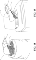
- the utensil 1 can include a flat bottom 24 and a wall 25 that extends as a vault from said bottom.
- the bottom 24 has preferably generally the shape of a circular sector with an arcuate free edge 26 ( figures 16-17 ) that protrudes with respect to the vaulted wall 25 to ease the collection of dust, crumbs or other particulate material.
- the vaulted wall 25 is made up of two flaps 27 folded and joined on the respective edges 12 in the same manner as previously described. On said joined edges 12 is also present, in the same way as previously explained, a handle 4.
- the configuration results from the previously described sheet 2, which will be provided with two creases (or weakened segments) 28 shown in figure 15 , which run from the third edge 8 to near the fourth edge 9. These creases allow the two flaps 27 to fold upon themselves to join each other as already described with reference to the previous variant embodiments.
- the utensil can be made in an extremely easy manner from a sheet of foldable material, such as for example a plastic material, a cardboard, an aluminum sheet, a wood product sheet properly adapted to be folded, leather.
- a sheet of foldable material such as for example a plastic material, a cardboard, an aluminum sheet, a wood product sheet properly adapted to be folded, leather.
- This sheet can be easily repaired, as it is sufficient to form a series of holes, openings and an appendix by means of punching, die cutting and similar production processes.
- buttons for locking the two edges of the sheet are also easy to make (or to find on the market), as is also the handle, which is just as simple to install.
- the utensil can also be disassembled and stored in a small place and rapidly reassembled as needed.
- the utensil is advantageously versatile because thanks to its structure it can be adapted as a container for collecting powdery solid or granular material or as a container for transferring liquids, thanks to the above-mentioned variant embodiments.
- the utensil 1 of the invention can be used as a container for pellets to be charged into a stove.
- the utensil 1 of the invention can be easily gripped to collect pellets from a conventional bag and can be folded so as to easily pour the pellets into the pellet charging opening on the stove without spilling any of them outside.
- Another great advantage is the possibility of considerably reducing the packaging and so making it possible to ship large quantities with a minimum encumbrance, while cutting handling costs and facilitating their storage arrangement.
- the materials with which the utensil can be produced also makes it possible to use it for handling food products (as for example to meter ingredients).
- the joining means of the two edges of the sheet can consist of a Velcro system, snap clips, tabs formed from a notch on said sheet that engage said holes or appropriate slots.
- Said funnel can also be formed from a rigid plastic material or can be a sort of preformed latex that can be adapted to the utensil.
- the appendage that closes the cone of the main body can be provided with fixing means to guarantee a closure that is different from the engagement with the slit previously described.
- fixing means for example, it is possible to use the same buttons described with reference to locking the edges of the sheet or Velcro systems can be used instead.
- the general forms of the utensil may change to suit specific requirements or preferences although the characteristic structure can be maintained to allow it to be disassembled and reassembled in the manner previously described so as to preserve the advantages associated with it.
- the sheet 2 has a shape generally identical to the shape of the previous embodiments. Furthermore, identical reference numerals indicate identical parts.
- the sheet 2 includes a first edge 12A provided with a plurality of holes 14 adapted to be reversibly engaged by corresponding buttons 3, and with openings 13 for the reversible engagement with gripping means 4.
- a second edge 12B preferably comprises only a plurality of holes 14 adapted to be engaged by the buttons 3, but it is not provided with the openings 13.
- the appendage 5 is provided with a hole 14 on its free end, in place of said cuts 11, such that it can be engaged by a corresponding button 3 as will be explained below.
- a further hole 14 is also provided on the sheet 2, near the fourth vertex 9 and proximal to the appendage, in place of the slit 15.
- the sheet 2 comprises two first creases 28 (or weakened segments) that run from the third vertex 8 and approach each other at the fourth vertex 9, generally like the creases described previously.
- a second crease 28C connects said two first creases transversally and divides them into a first portion 28A and a second portion 28B.
- the first portions start from the third vertex 8 and are substantially parallel, while the second portions start from the joining point with the second crease and extend toward the fourth vertex 9 in a converging trend.
- this arrangement of creases makes it possible to have a configuration of the utensil, when desired, such as to lean against a surface with the third vertex completely levelled, so as to favor the collection of any crumbs. Or else, the utensil can be used in its conical configuration.
- the reversible joining means 3 are identical to those previously described and, therefore, will not be described further.
- the gripping means 4 are generally similar to those previously described.
- said means are a handle with a flat and elongate portion 41 at whose extremities the tabs 42 are each provided with at least one length-adjusting hole 14, as will be explained later.
- the utensil 1 comprises a label 70 provided with a hole 14 made on a lateral portion 71.
- This label can be fixed reversibly on the sheet 2 so as to rotate on the same plane as the sheet and be alternatively exposed or concealed when the sheet is folded upon itself.
- the label makes it possible to display commercial information and/or usage details of the utensil 1, and can be imbued with essences to generate pleasant perfumes or absorb bad odors.
- the label can be made of absorbing material.
- the label can be fixed by means of said buttons 3, that engage both the hole 14 on the label and a hole provided near the first 6 or second 7 vertex of the sheet 2 ( figure 21 ).
- the utensil 1 can include hook means 50 adapted to suspend the utensil from a wall.
- said means are made from a longitudinal strip having a first end 51 provided with a first hole 14A and a second end 52 provided with a second hole 14B ( figure 20 ).
- the first hole is such as to be engaged by a button 3 like those previously described, while the second hole is such as to form a slot to be engaged, for example, by a nail, as described below.
- the second end 52 is provided with a slit 53 to facilitate the engagement with a nail or a pin when the spaces do not allow a frontal connection.
- the gripping means 4, the hooking means 50 and the label 70 are preferably and advantageously made with the same material as the sheet 2, and are obtained preferably by means of a die cutting process or similar processes.
- the utensil 1 may include a collecting spatula 60 consisting, for example, of a piece of semi-rigid, plastic and/or elastic and/or spongy material like polyurethane and foam rubber, which is used as a collecting means.
- This spatula can also be provided with a cut 61 that makes it possible to fix it removably to the sheet 2.
- FIG 21 in fact, is illustrated by means of arrows the position in which the handle 4, the label 70 and the hook means 50 are fixed by means of the respective buttons 3.
- the handle 4 is fixed to the first edge 12A of the sheet 2 by the engagement of a button 3 on a hole 14 of each of the two tabs 42 overlying a hole 14 of the first edge 12A, after the tabs have gone through the respective openings 13 and have been folded on the opposite side of the sheet 2 ( figure 23 ) with respect to the side where the flat portion 41 of the handle remains ( figure 22 ).
- the label 70 is fixed to the same folding face of the tabs 42 by a button that engages the hole 14 of its lateral portion 71 and the hole 14 of the sheet 2 on the second vertex 7.
- the hook means 50 are fixed to the hole 14 of the appendage 5 by means of a button 3, after having superimposed said hole with the first hole 14A of the first end 51 of the hook means.
- the sheet 2 can be folded upon itself, overlying the two edges 12A and 12B and inserting the stem 32 of each button of the first edge in the corresponding holes 14 of the second edge.
- the utensil 1 has thus achieved its conic configuration as described previously ( figures 25 and 26 ).
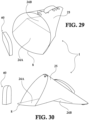
- the general conic shape of the device 1 can be reversibly modified so as to have a configuration such as to make dust collection easier.
- the second crease 28C transversal to the two first creases 28 it is possible to apply a pressure with a finger or against an edge or a corner, for example of a table, on such third crease, to obtain a collapse or a dipped deformation of the conic shape.
- first flat portion 24A comprised between the fourth vertex 8, the first portions 28A of said two first creases 28 and said second crease 28C, and a second flat portion 24B comprised between said second crease 28C and the second portions 28B of said two first creases 28.
- this deformation creates a first flat portion 24A such that the third vertex 8 is able to adapt perfectly to the surface to be cleaned ( figures 29 and 30 ).
- said first portion forms a collecting ramp followed by a descending plane (second flat portion 24B) which facilitates the holding of the collected dust.
- the collecting plane is uniformly inclined upwards during the collection with a brush, with the risk of allowing the dust just collected to fall back out of the scoop by gravity.
- the vaulted portion 25 of the utensil creates a lead-in for the dust toward said second portion 24B, preventing it from being scattered upward and returned toward the first portion 24A.
- the label 70 in its assembled configuration ( figure 31 ), said label is hidden inside the cone.
- the label rotates on the button 3 that fixes it to the cone and comes out at least partially from the cone so that it can be gripped and extracted ( figure 33 ).
- the information printed on it can be displayed or the essence contained in it can be released, for example by removing a protective film.
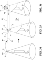
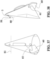
- the utensil 1 can be hung on a wall P, as shown in figure 34 .
- the tool can be hung from the wall P by engaging the second hole 14B with, for example, a nail 80 ( figure 35 ).
- the hook 50 It is also possible to hide the hook 50 thanks to its rotation on the button 3 that fixes the cone of the utensil 1, as shown in figure 36 , where it can be seen that the rotation shown by the arrow allows the utensil to lift from the horizontal line 81 on which the nail lies and to cover it with a pleasant effect of suspension in the air.
- the label of the variant of figure 20 can be applied with any of the embodiments previously described and illustrated in figures 1 to 19 .
- the funnel 20 can be applied to the embodiment of figure 20 .
- the inside of the utensil can be lined with a common plastic bag for the collection of unsorted waste or with a biodegradable ecological bag for collecting organic household waste.
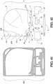
- Figures 39-40 illustrate a composition 99 of all the components of the utensil 1 of the invention assembled and contained in a support 100.
- the support 100, the utensil 1 and its accessories are made from the same sheet of material and preferably by means of a die cutting process.
- the utensil 1 and its accessories in this version are held on the support 100 by detaining points formed on the material along the lines and portions that delimit the geometrical shapes of the utensil and of its accessories.
- detaining points formed on the material along the lines and portions that delimit the geometrical shapes of the utensil and of its accessories.
- the support 100 is formed by a first portion 101 or main portion and a second portion 102 or secondary portion.
- the main portion 101 carries the sheet 2 which will form the body 10 of the utensil, while the secondary portion 102 carries the accessories of the utensil.
- the two portions are joined to each other along two respective first edges 103 and 104 preferably by means of bending bridges 105.
- the first portion 101 comprises the sheet 2 that will form the body 10 of the utensil 1.
- This sheet substantially corresponds to the one described earlies and, therefore it will not be detailed and in the figures it will have the same reference numerals.
- the sheet 2 is provided with said buttons 3 already engaged in the corresponding holes 14 of its first edge 12A.
- the first edge 12A comprises openings 13A to engage the tabs 42 of the handle 4, and the second edge 12B comprises cuts 13B to engage said tabs.
- the appendage 5 is connected with the fourth edge 9 of the sheet 2 by means of a crease line 54 that facilitates its bending.
- a set of creases 55 extend then from said fourth edge of the sheet: two toward the second portions 28B of said creases 28 and one toward the second edge 12b of the sheet ( figure 42 ).
- the secondary portion 102 comprises, for example, the handle 4 previously described, one or more labels 70 and/or spatulas 72, a hook 50, a felt-tip pen holder 90.
- the label corresponds to the one previously described; the spatula has a shape that is generally identical to the label and with its structure it is particularly adapted for collecting crumbs, debris, dust, or to be used as a scraper.
- the hook 50 also is the one previously described and is provided with the corresponding button 3, while the pen holder 90, as is better illustrated in figure 42 , consists of a flat portion generally having the shape of a T in which the stem is attached to the head through a weakened segment 91, as well as the head is longitudinally divided by a weakened part 92 of the same.
- figure 43 is shown a first step of assembling the utensil of the invention. After having detached the sheet 2 from said support 100, by breaking the detaining points or the weakened edging segments ( figure 42 ), the sheet 2 is bent along the second crease 28C toward the face of the sheet from which the heads 31 of the buttons 3 protrude. This operation can be carried out by using, for example, the edge of a table.
- the sheet 2 is linked to itself by engaging the stems 32 of the buttons 3 of the first edge 12A with the holes 14 of the second edge 12B, closing the body 10 of the utensil ( figure 46 ).
- the hook 50 can be applied to the appendage 5 of the sheet 2 by inserting the stem 32 of its button 3 into the hole 14 of the appendage ( figures 47-48 ). Finally, the appendage 5 is bent (this operation is facilitated thanks to the crease 54) until the stem 32 of said button 3 engages the hole 14 formed near the fourth vertex 9 of the sheet itself ( figures 49-50 ), this operation will join the base of the appendage (corresponding to the crease 54) with the vertex 9 and cause a sort of sealing. This closing operation is facilitated not only by said crease line 54 but also by the creases 55.
- the handle 4 is mounted by inserting each of the respective tabs 42 first into an opening 13A of the first edge 12A of the sheet 2 and then into the cut 13B of the second edge 12B which now is superimposed on the first edge, bending them toward the flat portion 41 of the handle. Finally, the respective holes 14 are engaged with the stems 32 of the buttons 3 according to the desired lengths ( figure 51 ). It should be noted that the cut 13B is not in a real hole, therefore it guarantees a sealing against any accidental escape of dust or other collected material.
- the spatula 72 is applied internally to the body 10 of the utensil by engaging its hole 14 with the button 3 that is nearest to the opening of the cone ( figure 52 ).
- the specific button-type joining means also make it possible, among the closing of the utensil, to link and make, simply and quickly, any adjustment of all the components.
- the creases, or weakened segments have the function of facilitating bending. This result can also be obtained by using incisions, for example shallow cuts, or similar procedures.
- these variants can be used to facilitate the bending of the portions of the sheet where inclined planes or closures are to be created, as in the above case of the broken lines 28 that advantageously allow the easy and immediate deformation of parts of the cone into flat surfaces that facilitate the collection of material.
Landscapes
- Packages (AREA)
- Food-Manufacturing Devices (AREA)
- Table Devices Or Equipment (AREA)
Claims (18)
- - Ustensile (1) comprenant un corps principal (10) sous la forme d'un cône creux, caractérisé par le fait que ledit corps principal est formé en le refermant sur lui-même le long de deux bords contigus (12) d'une feuille (2) de matière pliable, des moyens (3) pour lier de manière réversible lesdits deux bords, des moyens de préhension (4) pour manipuler ledit ustensile, des moyens de fermeture (5) pour fermer de manière réversible le sommet du corps principal (10).
- - Ustensile (1) selon la revendication 1, dans lequel ladite feuille (2) a généralement une forme de losange dans une vue en plan, avec quatre sommets, un premier sommet (6) opposé à un deuxième sommet (7) le long d'un plus grand diamètre (D1), un troisième sommet (8) opposé à un quatrième sommet (9) le long d'un plus petit diamètre (D2).
- - Ustensile (1) selon la revendication 2, dans lequel lesdits quatre sommets sont arrondis, la courbe du troisième sommet (8) s'étendant plus loin par rapport à la courbe du quatrième sommet (9).
- - Ustensile (1) selon la revendication 2 ou 3, dans lequel à partir du quatrième sommet (9) s'étend un appendice (5) qui forme les moyens de fermeture réversible susmentionnés du sommet du corps principal (10).
- - Ustensile (1) selon l'une quelconque des revendications 2 à 4, dans lequel le long des deux bords (12) de la feuille qui divergent à partir du quatrième sommet (9) sont prévues des ouvertures (13) pour engager de manière réversible lesdits moyens de préhension (4).
- - Ustensile (1) selon l'une quelconque des revendications de 2 à 5, dans lequel le long des deux bords (12) de la feuille qui divergent à partir du quatrième sommet (9) est présente une pluralité de trous (14) agencés pour être engagés de manière réversible par lesdits moyens de liaison (3).
- - Ustensile (1) selon la revendication 5 ou 6, dans lequel lesdits moyens de préhension (4) sont une poignée comprenant une partie plate et allongée (41) dont les extrémités divergent en languettes (42) qui s'engagent avec les ouvertures (13) desdits bords (12).
- - Ustensile (1) selon l'une quelconque des revendications 5 à 7, dans lequel lesdits moyens de liaison (3) sont des boutons ayant dans l'ensemble une forme de champignon avec une tête en forme de disque (31) et une tige arrondie (32) pour s'engager avec les trous (14) desdits bords (12).
- - Ustensile (1) selon l'une quelconque des revendications de 1 à 8, comprenant également une doublure partielle (17) de la feuille (2), ladite doublure comportant au moins un bord (18) ancré à la surface de la feuille et, de préférence, une languette de préhension (19) pour tourner la doublure à partir du côté de la paroi interne opposé aux bords (12) superposés, jusqu'auxdits bords pour couvrir la ligne de superposition des bords.
- - Ustensile (1) selon l'une quelconque des revendications de 1 à 9, comprenant un entonnoir (20) ou un gant qui s'adapte à l'intérieur de celui-ci, l'entonnoir comportant un bord annulaire (21) qui se plie sur la première extrémité élargie (22) et un tube de vidage étroit (23) à sa seconde extrémité effilée (24).
- - Ustensile (1) selon l'une quelconque des revendications de 1 à 10, dans lequel ladite feuille (2) comprend un fond plat (24) et une paroi (25) qui s'étend à partir dudit fond sous la forme d'une voûte, le fond (24) a, de préférence, une forme générale de secteur circulaire avec un bord libre arqué (26) qui fait saillie par rapport à la paroi (25), constituée de deux volets (27) pliés et liés sur les bords respectifs (12) de la feuille.
- - Ustensile (1) selon l'une quelconque des revendications de 1 à 11, comprenant une brosse (16) ou une spatule de collecte (60).
- - Ustensile (1) selon l'une quelconque des revendications de 2 à 12, comprenant deux premiers plis (28) qui s'étendent à partir dudit troisième sommet (8) vers ledit quatrième sommet (9) et un second pli (28C) transversal entre lesdits deux premiers plis de façon à marquer une première partie (24A) et une seconde partie (24B) de ladite feuille (2) qui peuvent être déformées dans deux plans inclinés l'un par rapport à l'autre.
- - Ustensile (1) selon l'une quelconque des revendications de 2 à 13, comprenant également une étiquette (70) reliée de manière amovible audit deuxième sommet (7) de la feuille (2) de façon à tourner sur le plan de la feuille elle-même pour la chevaucher presque entièrement.
- - Ustensile (1) selon l'une quelconque des revendications de 4 à 14, dans lequel ledit appendice (5) comprend un trou (14) sur son extrémité libre, agencé pour être engagé par un moyen de liaison (3) qui le lie de manière réversible à un trou (14) formé sur la feuille (2) à proximité dudit quatrième sommet (9).
- - Ustensile (1) selon l'une quelconque des revendications de 7 à 15, dans lequel ladite poignée (4) comprend au moins un trou (14) formé sur lesdites languettes (42) pour s'engager avec un moyen de liaison (3) après avoir été superposé avec un trou correspondant (14) formé sur ladite feuille (2) à ses deux bords (12).
- - Ustensile (1) selon l'une quelconque des revendications de 4 à 16, dans lequel ledit appendice (5) comprend des moyens d'accrochage (50) appropriés pour suspendre l'ustensile.
- - Ustensile (1) selon l'une quelconque des revendications de 12 à 17, dans lequel ladite spatule de collecte (60) est constituée d'un morceau de matière semirigide, plastique et/ou élastique, et/ou spongieuse telle que du polyuréthane et du caoutchouc mousse, qui peut également comporter une découpe (61) qui permet de le fixer de manière amovible à la feuille (2).
Applications Claiming Priority (3)
| Application Number | Priority Date | Filing Date | Title |
|---|---|---|---|
| IT202019000003584U IT201900003584U1 (it) | 2019-10-10 | 2019-10-10 | Utensile per la raccolta e il versamento di prodotti solidi o liquidi |
| IT202000000199 | 2020-01-17 | ||
| PCT/IB2020/056728 WO2021069978A1 (fr) | 2019-10-10 | 2020-07-17 | Ustensile pour collecter et verser des produits solides ou liquides |
Publications (2)
| Publication Number | Publication Date |
|---|---|
| EP4041042A1 EP4041042A1 (fr) | 2022-08-17 |
| EP4041042B1 true EP4041042B1 (fr) | 2024-04-10 |
Family
ID=72356208
Family Applications (1)
| Application Number | Title | Priority Date | Filing Date |
|---|---|---|---|
| EP20767595.0A Active EP4041042B1 (fr) | 2019-10-10 | 2020-07-17 | Ustensile por ramasser et verser des produits solides et liquides |
Country Status (7)
| Country | Link |
|---|---|
| US (1) | US20220322910A1 (fr) |
| EP (1) | EP4041042B1 (fr) |
| JP (1) | JP2022552117A (fr) |
| KR (1) | KR20220081985A (fr) |
| CN (1) | CN114502053A (fr) |
| CA (1) | CA3152684A1 (fr) |
| WO (1) | WO2021069978A1 (fr) |
Family Cites Families (16)
| Publication number | Priority date | Publication date | Assignee | Title |
|---|---|---|---|---|
| CH391212A (de) * | 1962-01-12 | 1965-04-30 | Bp Benzin & Petroleum Ag | Kehrichtschaufel |
| DE3612895A1 (de) * | 1986-04-17 | 1987-10-29 | Altstaedter Verpack Vertrieb | Fluessigkeitspackung mit griff |
| US6102278A (en) * | 1999-04-19 | 2000-08-15 | Rothas; William J. | Foldable pan |
| JP2005288133A (ja) * | 2004-04-05 | 2005-10-20 | Motoko Fujiwara | メガホン型ちりとり |
| DE202004007969U1 (de) * | 2004-05-18 | 2005-09-29 | Seda S.P.A., Arzano | Behälter |
| JP4592348B2 (ja) * | 2004-07-21 | 2010-12-01 | サンスター株式会社 | ブリスターパック及びその製造方法 |
| CN2855958Y (zh) * | 2006-01-12 | 2007-01-10 | 缪文堍 | 一种折叠式笔包装盒 |
| JP2008114014A (ja) * | 2006-11-04 | 2008-05-22 | Makiko Ujiie | 折り畳みちりとり |
| CN101659339B (zh) * | 2009-09-17 | 2011-03-16 | 友达光电股份有限公司 | 包装结构 |
| US20150021224A1 (en) * | 2011-01-05 | 2015-01-22 | Ziba Labs Llc | Packaging with pre-formed plastic web including user-graspable tear tab |
| CN202089310U (zh) * | 2011-06-01 | 2011-12-28 | 江南大学 | 板片折叠式两件套包装 |
| SE1250463A1 (sv) * | 2012-05-07 | 2013-11-08 | Sandvik Intellectual Property | Förpackning |
| WO2014059369A1 (fr) * | 2012-10-11 | 2014-04-17 | Ecotensil Inc. | Ustensiles à construire |
| JP6718649B2 (ja) * | 2016-08-04 | 2020-07-08 | 貴行 古田 | 組立式の紙製塵取り |
| US20180317736A1 (en) * | 2017-06-27 | 2018-11-08 | Brett I. GOLDBERG | Disposable Cleaning Utensils Capable of Being Incorporated into Boxes and Containers and Methods of Creating Disposable Cleaning Utensils |
| CN208463978U (zh) * | 2018-01-29 | 2019-02-05 | 三明学院 | 一种对折式畚斗 |
-
2020
- 2020-07-17 JP JP2022519373A patent/JP2022552117A/ja active Pending
- 2020-07-17 CN CN202080070962.8A patent/CN114502053A/zh active Pending
- 2020-07-17 US US17/761,834 patent/US20220322910A1/en active Pending
- 2020-07-17 EP EP20767595.0A patent/EP4041042B1/fr active Active
- 2020-07-17 KR KR1020227011542A patent/KR20220081985A/ko unknown
- 2020-07-17 CA CA3152684A patent/CA3152684A1/fr active Pending
- 2020-07-17 WO PCT/IB2020/056728 patent/WO2021069978A1/fr unknown
Also Published As
| Publication number | Publication date |
|---|---|
| JP2022552117A (ja) | 2022-12-15 |
| EP4041042A1 (fr) | 2022-08-17 |
| CN114502053A (zh) | 2022-05-13 |
| US20220322910A1 (en) | 2022-10-13 |
| KR20220081985A (ko) | 2022-06-16 |
| WO2021069978A1 (fr) | 2021-04-15 |
| CA3152684A1 (fr) | 2021-04-15 |
Similar Documents
| Publication | Publication Date | Title |
|---|---|---|
| US5705212A (en) | Food package with an enclosed eating utensil | |
| US3557853A (en) | Sanitary napkin holder | |
| US4116330A (en) | Combination package and display case | |
| US5788080A (en) | Stacked openable and reclosable plastic bags on a dispenser | |
| JP3081188B2 (ja) | 装飾用袋 | |
| US20170050763A1 (en) | Apparatus for dispensing seeds and receiving skins | |
| US20150001227A1 (en) | Pan having secured thereto roastin materials | |
| US20080073244A1 (en) | Package closure device | |
| SE507647C2 (sv) | Stora eller tunga förpackningar med återförslutningstopp | |
| EP4041042B1 (fr) | Ustensile por ramasser et verser des produits solides et liquides | |
| US2093974A (en) | Package or container | |
| US9169049B2 (en) | Devices suitable for removing, preparing, and storing materials | |
| US20120224791A1 (en) | Flat foldable, amusement providing, ecofriendly waste containers | |
| US7591496B1 (en) | Up-right carry-out | |
| RU2816164C1 (ru) | Устройство для собирания и пересыпания твердых или переливания жидких продуктов, ложемент для листа устройства | |
| JPH01167071A (ja) | 小物類の販売及び搬送用包装体 | |
| US3986606A (en) | Dual purpose container label | |
| US7819244B2 (en) | Reconstitution package | |
| US20030024842A1 (en) | Stick and dip condiment container | |
| RU185696U1 (ru) | Складная упаковка для порционного пищевого продукта | |
| SE1650309A1 (en) | Packaging container for scoopable contents. | |
| AU2002317292A1 (en) | Reconstitution package | |
| US20220340333A1 (en) | Storage container with internal release mechanism | |
| US20060102273A1 (en) | Method for preserving a perishable product | |
| US3012691A (en) | Tray doily |
Legal Events
| Date | Code | Title | Description |
|---|---|---|---|
| STAA | Information on the status of an ep patent application or granted ep patent |
Free format text: STATUS: UNKNOWN |
|
| STAA | Information on the status of an ep patent application or granted ep patent |
Free format text: STATUS: THE INTERNATIONAL PUBLICATION HAS BEEN MADE |
|
| PUAI | Public reference made under article 153(3) epc to a published international application that has entered the european phase |
Free format text: ORIGINAL CODE: 0009012 |
|
| STAA | Information on the status of an ep patent application or granted ep patent |
Free format text: STATUS: REQUEST FOR EXAMINATION WAS MADE |
|
| 17P | Request for examination filed |
Effective date: 20220321 |
|
| AK | Designated contracting states |
Kind code of ref document: A1 Designated state(s): AL AT BE BG CH CY CZ DE DK EE ES FI FR GB GR HR HU IE IS IT LI LT LU LV MC MK MT NL NO PL PT RO RS SE SI SK SM TR |
|
| DAV | Request for validation of the european patent (deleted) | ||
| DAX | Request for extension of the european patent (deleted) | ||
| P01 | Opt-out of the competence of the unified patent court (upc) registered |
Effective date: 20230328 |
|
| GRAP | Despatch of communication of intention to grant a patent |
Free format text: ORIGINAL CODE: EPIDOSNIGR1 |
|
| STAA | Information on the status of an ep patent application or granted ep patent |
Free format text: STATUS: GRANT OF PATENT IS INTENDED |
|
| GRAJ | Information related to disapproval of communication of intention to grant by the applicant or resumption of examination proceedings by the epo deleted |
Free format text: ORIGINAL CODE: EPIDOSDIGR1 |
|
| STAA | Information on the status of an ep patent application or granted ep patent |
Free format text: STATUS: REQUEST FOR EXAMINATION WAS MADE |
|
| INTG | Intention to grant announced |
Effective date: 20231102 |
|
| GRAP | Despatch of communication of intention to grant a patent |
Free format text: ORIGINAL CODE: EPIDOSNIGR1 |
|
| STAA | Information on the status of an ep patent application or granted ep patent |
Free format text: STATUS: GRANT OF PATENT IS INTENDED |
|
| INTC | Intention to grant announced (deleted) | ||
| INTG | Intention to grant announced |
Effective date: 20231222 |
|
| GRAS | Grant fee paid |
Free format text: ORIGINAL CODE: EPIDOSNIGR3 |
|
| GRAA | (expected) grant |
Free format text: ORIGINAL CODE: 0009210 |
|
| STAA | Information on the status of an ep patent application or granted ep patent |
Free format text: STATUS: THE PATENT HAS BEEN GRANTED |
|
| AK | Designated contracting states |
Kind code of ref document: B1 Designated state(s): AL AT BE BG CH CY CZ DE DK EE ES FI FR GB GR HR HU IE IS IT LI LT LU LV MC MK MT NL NO PL PT RO RS SE SI SK SM TR |
|
| REG | Reference to a national code |
Ref country code: GB Ref legal event code: FG4D |
|
| REG | Reference to a national code |
Ref country code: CH Ref legal event code: EP |
|
| REG | Reference to a national code |
Ref country code: DE Ref legal event code: R096 Ref document number: 602020028831 Country of ref document: DE |
|
| REG | Reference to a national code |
Ref country code: IE Ref legal event code: FG4D |