EP4040799B1 - Microphone and speaker combined module, earphones, and terminal device - Google Patents
Microphone and speaker combined module, earphones, and terminal device Download PDFInfo
- Publication number
- EP4040799B1 EP4040799B1 EP20890501.8A EP20890501A EP4040799B1 EP 4040799 B1 EP4040799 B1 EP 4040799B1 EP 20890501 A EP20890501 A EP 20890501A EP 4040799 B1 EP4040799 B1 EP 4040799B1
- Authority
- EP
- European Patent Office
- Prior art keywords
- microphone
- loudspeaker
- membrane
- side wall
- pcb
- Prior art date
- Legal status (The legal status is an assumption and is not a legal conclusion. Google has not performed a legal analysis and makes no representation as to the accuracy of the status listed.)
- Active
Links
Images


Classifications
-
- H—ELECTRICITY
- H04—ELECTRIC COMMUNICATION TECHNIQUE
- H04R—LOUDSPEAKERS, MICROPHONES, GRAMOPHONE PICK-UPS OR LIKE ACOUSTIC ELECTROMECHANICAL TRANSDUCERS; ELECTRIC HEARING AIDS; PUBLIC ADDRESS SYSTEMS
- H04R1/00—Details of transducers, loudspeakers or microphones
- H04R1/10—Earpieces; Attachments therefor ; Earphones; Monophonic headphones
- H04R1/1083—Reduction of ambient noise
-
- H—ELECTRICITY
- H04—ELECTRIC COMMUNICATION TECHNIQUE
- H04R—LOUDSPEAKERS, MICROPHONES, GRAMOPHONE PICK-UPS OR LIKE ACOUSTIC ELECTROMECHANICAL TRANSDUCERS; ELECTRIC HEARING AIDS; PUBLIC ADDRESS SYSTEMS
- H04R1/00—Details of transducers, loudspeakers or microphones
- H04R1/02—Casings; Cabinets ; Supports therefor; Mountings therein
- H04R1/04—Structural association of microphone with electric circuitry therefor
-
- H—ELECTRICITY
- H04—ELECTRIC COMMUNICATION TECHNIQUE
- H04R—LOUDSPEAKERS, MICROPHONES, GRAMOPHONE PICK-UPS OR LIKE ACOUSTIC ELECTROMECHANICAL TRANSDUCERS; ELECTRIC HEARING AIDS; PUBLIC ADDRESS SYSTEMS
- H04R1/00—Details of transducers, loudspeakers or microphones
- H04R1/08—Mouthpieces; Microphones; Attachments therefor
-
- H—ELECTRICITY
- H04—ELECTRIC COMMUNICATION TECHNIQUE
- H04R—LOUDSPEAKERS, MICROPHONES, GRAMOPHONE PICK-UPS OR LIKE ACOUSTIC ELECTROMECHANICAL TRANSDUCERS; ELECTRIC HEARING AIDS; PUBLIC ADDRESS SYSTEMS
- H04R1/00—Details of transducers, loudspeakers or microphones
- H04R1/10—Earpieces; Attachments therefor ; Earphones; Monophonic headphones
- H04R1/1058—Manufacture or assembly
- H04R1/1075—Mountings of transducers in earphones or headphones
-
- H—ELECTRICITY
- H04—ELECTRIC COMMUNICATION TECHNIQUE
- H04R—LOUDSPEAKERS, MICROPHONES, GRAMOPHONE PICK-UPS OR LIKE ACOUSTIC ELECTROMECHANICAL TRANSDUCERS; ELECTRIC HEARING AIDS; PUBLIC ADDRESS SYSTEMS
- H04R1/00—Details of transducers, loudspeakers or microphones
- H04R1/10—Earpieces; Attachments therefor ; Earphones; Monophonic headphones
- H04R1/1091—Details not provided for in groups H04R1/1008 - H04R1/1083
-
- H—ELECTRICITY
- H04—ELECTRIC COMMUNICATION TECHNIQUE
- H04R—LOUDSPEAKERS, MICROPHONES, GRAMOPHONE PICK-UPS OR LIKE ACOUSTIC ELECTROMECHANICAL TRANSDUCERS; ELECTRIC HEARING AIDS; PUBLIC ADDRESS SYSTEMS
- H04R5/00—Stereophonic arrangements
- H04R5/033—Headphones for stereophonic communication
-
- H—ELECTRICITY
- H04—ELECTRIC COMMUNICATION TECHNIQUE
- H04R—LOUDSPEAKERS, MICROPHONES, GRAMOPHONE PICK-UPS OR LIKE ACOUSTIC ELECTROMECHANICAL TRANSDUCERS; ELECTRIC HEARING AIDS; PUBLIC ADDRESS SYSTEMS
- H04R2201/00—Details of transducers, loudspeakers or microphones covered by H04R1/00 but not provided for in any of its subgroups
- H04R2201/003—Mems transducers or their use
Definitions
- This application relates to the field of wireless headset technologies, and in particular, to a microphone-loudspeaker combined module, a headset, and a terminal device.
- TWS Truste Wireless Stereo, true wireless stereo
- Bluetooth headset technology brings numerous sensors to a TWS headset, resulting in increasingly high integration of headset elements and increasingly deficient space inside the headset.
- a microphone is usually disposed between a loudspeaker (also referred to as a horn) and an ear canal.
- the microphone is configured to pick up a surrounding noise signal and reversely transmit the noise signal to the loudspeaker by using a circuit.
- the reverse noise signal that is output by the loudspeaker cancels out a noise signal directly entering the ear, to reduce the noise.
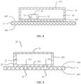
- FIG. 1 is a schematic diagram of a cross section of an existing (noise cancellation) headset.
- the headset includes a first housing 11' and a second housing 12'.
- a magnetic circuit system 21' of a loudspeaker 2' is disposed in the first housing 11'.
- a membrane 22' of the loudspeaker 2' and the second housing 12' form a front cavity 13' of the loudspeaker 2'.
- the loudspeaker 2' and a microphone 3' are independently disposed components.
- the microphone 3' is fastened to a PCB (Printed Circuit Board, printed circuit board) 4'.
- the PCB 4' is disposed outside the second housing 12'.
- the loudspeaker 2' and the PCB 4' are electrically connected by using an FPC (Flexible Printed Circuit, flexible printed circuit) (not shown in the diagram).
- FPC Flexible Printed Circuit, flexible printed circuit
- the front cavity 13' of the loudspeaker 2' is squeezed due to a way of disposing the microphone 3', and consequently a cross-sectional area of an acoustic radiation tube 131' of the front cavity 13' is reduced, thereby affecting a high-frequency response of the loudspeaker 2' and deteriorating a high-frequency sound effect of the headset.
- a microphone-loudspeaker combined module, a headset, and a terminal device are in urgent need to resolve the foregoing problem.
- EP 1 396 983 A1 describes a structural arrangement for a radio communication terminal incorporating a loudspeaker and earpiece.
- WO 2011/061483 A2 describes a production of ambient noise-cancelling earphones.
- an objective of this application is to provide a microphone-loudspeaker combined module, a headset, and a terminal device, to resolve a problem that a loudspeaker and a microphone occupy large space.
- a technical solution of this application provides a microphone-loudspeaker combo module according to claim 1.
- the microphone and the loudspeaker are disposed integrally. Compared with separate arrangement of the microphone and the loudspeaker, this integral arrangement can further improve space utilization of the microphone and the loudspeaker.
- the microphone and the loudspeaker form a first integrated body, where the first integrated body includes:
- the microphone rear cavity is formed among the first bottom wall, the first side wall, the second side wall, and the first membrane
- the loudspeaker rear cavity is formed among the first bottom wall, the first side wall, the second side wall, and the second membrane, and there is a gap between the first membrane and the second membrane.
- the microphone front cavity is formed on a side of the first membrane opposite to the microphone rear cavity
- the loudspeaker front cavity is formed on a side of the second membrane opposite to the loudspeaker rear cavity.
- first membranes there is a plurality of first membranes, and there is a gap between two adjacent first membranes, thereby facilitating vibration of the first membrane.
- the microphone and the loudspeaker form a second integrated body, where the second integrated body includes:
- the microphone rear cavity is formed among the second bottom wall, the fourth side wall, and the first membrane
- the loudspeaker rear cavity is formed among the second bottom wall, the third side wall, the fourth side wall, and the second membrane, and there is a gap between the first membrane and the second membrane.
- the microphone front cavity is formed on a side of the first membrane opposite to the microphone rear cavity
- the loudspeaker front cavity is formed on a side of the second membrane opposite to the loudspeaker rear cavity.
- first membrane disposed at the center of the second integrated body.
- the microphone of the headset is mainly configured to pick up external noise
- a cross-sectional area of the first membrane does not need to be very large, for example, the first membrane may be at the center of the second integrated body.
- the microphone and the loudspeaker are made by using a MEMS process, thereby facilitating integration of the microphone and the loudspeaker.
- the microphone, the loudspeaker, and the signal processing unit are fastened to the PCB by using an SMT process, thereby resolving a problem of sound effect inconsistency caused by a difference in manually assembled modules of the entire machine, and improving product reliability.
- the signal processing unit includes:
- the first signal processing unit includes an ASIC chip
- the second signal processing unit includes a DSP chip.
- the ASIC chip is used to drive the microphone and the loudspeaker
- the DSP chip is used to reversely process an electrical signal of noise.
- a first through hole is disposed on the PCB, a second through hole is disposed on the loudspeaker, and the first through hole communicates with the second through hole, to ensure a pressure balance between the loudspeaker rear cavity and the environment.
- a technical solution of this application provides a headset, including:
- a rear cavity of the microphone and the loudspeaker is formed between the first housing and the PCB, and a front cavity of the microphone and the loudspeaker is formed between the second housing and the PCB. In this way, the microphone and the loudspeaker can share the front cavity, thereby improving space utilization of the microphone and the loudspeaker.
- the second housing includes an ear-in part, a sound output hole is disposed in the ear-in part, the sound output hole communicates with the front cavity, and a damping net is disposed in the ear-in part.
- a high-frequency sound made by the loudspeaker can be filtered out by setting the damping net, thereby making a bass effect of the headset more remarkable.
- the second housing further includes a first stepped part connected to the ear-in part, and the loudspeaker and the microphone are disposed in an internal cavity of the first stepped part; and an inner diameter of the first stepped part is greater than that of the ear-in part, to increase a volume of the front cavity to a maximum extent.
- the second housing further includes a second stepped part connected to the first stepped part, and the second stepped part is fastened to the first housing; and an inner diameter of the second stepped part is greater than that of the first stepped part, a step is disposed in the second stepped part, and the PCB is fastened to the step, to accommodate the microphone-loudspeaker combined module.
- a technical solution of this application provides a terminal device, including the microphone-loudspeaker combined module described above, to reduce space occupied by the microphone and the loudspeaker on the terminal device.
- the microphone front cavity of the microphone communicates with the loudspeaker front cavity of the loudspeaker, so that the microphone and the loudspeaker can share the front cavity, thereby improving space utilization of the microphone and the loudspeaker, and resolving a problem that the loudspeaker and the microphone occupy large space.
- some terminal devices have functions of picking up a sound and making a sound, in other words, have acoustic components such as a microphone and a loudspeaker.
- acoustic components such as a microphone and a loudspeaker.
- these acoustic components are independently disposed components on the terminal device, and occupy large internal space of the terminal device.
- an embodiment of this application provides a terminal device.
- a microphone-loudspeaker combined module is disposed on the terminal device.
- the microphone-loudspeaker combined module can integrate a microphone and a loudspeaker on a PCB, to reduce space occupied by the microphone and the loudspeaker.
- the terminal device may be, for example, a head-mounted device (specifically AR glasses or VR glasses); or may be, for example, a portable device (specifically a headset, a mobile phone, or a wristband); or may be certainly another product having a sound pickup function and a sound making function, and enumeration is not performed herein.
- the terminal device may be a headset.
- the headset may be a TWS (True Wireless Stereo, true wireless stereo) wireless Bluetooth headset.
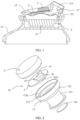
- FIG. 2 is a schematic exploded view of a headset according to an embodiment of this application.
- the headset includes a first housing 11 and a second housing 12.
- Space for accommodating a microphone-loudspeaker combined module 10 is formed between the first housing 11 and the second housing 12.
- the microphone-loudspeaker combined module 10 includes a loudspeaker 2, a microphone 3, and a PCB 4.
- the loudspeaker 2 and the microphone 3 are fastened to the PCB 4.
- a signal processing unit configured to process an electrical signal, for example, a signal processing chip, may be further disposed on the PCB 4.
- the loudspeaker 2 and the microphone 3 are electrically connected to the signal processing unit by using the PCB 4 separately.
- the signal processing unit may include a first signal processing unit and a second signal processing unit.
- the first signal processing unit is a first signal processing chip 41
- the second signal processing unit is a second signal processing chip 42.
- the loudspeaker 2 and the microphone 3 are electrically connected to the first signal processing chip 41 by using the PCB 4 separately
- the first signal processing chip 41 is electrically connected to the second signal processing chip 42 by using the PCB 4.
- the first signal processing unit can match output impedance of the microphone 3 and achieve a more balanced effect for call and audio quality.
- the second signal processing unit can reversely process an electrical signal of noise to implement active noise cancellation.
- the loudspeaker 2, the microphone 3, the first signal processing chip 41, and the second signal processing chip 42 are all welded on the PCB 4, for example, by using an SMT (Surface Mount Technology, surface mount technology).
- the first signal processing chip 41 includes but is not limited to an ASIC (Application-Specific Integrated Circuit, application-specific integrated circuit) chip, and may further include, for example, an FPGA (Field Programmable Gate Array, field programmable gate array) chip or a DSP (Digital Signal Processor, digital signal processor) chip.
- ASIC Application-Specific Integrated Circuit, application-specific integrated circuit
- FPGA Field Programmable Gate Array, field programmable gate array
- DSP Digital Signal Processor, digital signal processor
- the second signal processing chip 42 includes but is not limited to a DSP chip, and may further include, for example, an FPGA chip, or a BT SOC (Bluetooth System on Chip, Bluetooth system on chip, in other words, Bluetooth chip) integrated with a DSP chip (or an FPGA chip).
- a DSP chip or an FPGA chip.
- BT SOC Bluetooth System on Chip, Bluetooth system on chip, in other words, Bluetooth chip
- the first signal processing chip 41 may include one ASIC chip.
- the ASIC chip can match output impedance of the microphone 3 and achieve a more balanced effect for call and audio quality. It may be understood that the first signal processing chip 41 may alternatively include two ASIC chips.
- the front ASIC chip can match output impedance of the microphone 3, and the back ASIC chip can achieve a more balanced effect for call and audio quality.
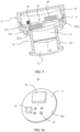
- FIG. 3 is a schematic diagram of a cross section of a headset according to an embodiment of this application.
- a rear cavity 14 of a loudspeaker 2 and a microphone 3 is formed between a first housing 11 and a PCB 4, and a front cavity 15 of the loudspeaker 2 and the microphone 3 is formed between a second housing 12 and the PCB 4.
- the PCB 4 divides space accommodating a microphone-loudspeaker combined module 10 into the rear cavity 14 and the front cavity 15.
- the loudspeaker 2 and the microphone 3 share the front cavity 15 to improve space utilization of the loudspeaker 2 and the microphone 3.
- the loudspeaker 2 is disposed in the front cavity 15, the front cavity 15 is not squeezed, and a cross-sectional area of a acoustic radiation tube is not reduced. Therefore, not only internal space of the headset is saved, but also a high-frequency sound effect of the loudspeaker 2 can be ensured.
- the second housing 12 includes an ear-in part 121 for inserting into a human ear canal, a sound output hole 13 is disposed in the ear-in part 121, and a sound made by the loudspeaker 2 can be transmitted to a human ear through the front cavity 15 and the sound output hole 13.
- a soft rubber sleeve (not shown in the diagram) is disposed outside the ear-in part 121, there may be a gap between the soft rubber sleeve and the human ear due to insufficient sealing property. External noise may enter the sound output hole 13 from the outside through the gap, then enter the front cavity 15, and then be picked up by the microphone 3. Alternatively, external noise may be picked up by the microphone 3 through the sound output hole 13 and the front cavity 15.
- the microphone 3 processes a sound signal, for example, may convert the sound signal into an electrical signal, and transfers the electrical signal to a first signal processing chip 41 for processing.
- An audio electrical signal generated after processing by the first signal processing chip 41 is transferred to a second signal processing chip 42 for reverse processing.
- the loudspeaker 2 converts an electrical signal obtained after the reverse processing into a sound signal for sending, to implement active noise cancellation.
- the electrical signal is transferred through the PCB 4.
- the second housing 12 further includes a first stepped part 122 connected to the ear-in part 121, and the loudspeaker 2 and the microphone 3 are disposed in an internal cavity of the first stepped part 122.
- the first stepped part 122 is located at a part in which the headset is not inserted into or just inserted in the ear canal.
- An inner diameter of the first stepped part 122 is greater than that of the ear-in part 121, and the front cavity 15 includes the internal cavity of the first stepped part 122. In this way, by disposing the first stepped part 122, a volume of the front cavity 15 can be increased to a maximum extent.
- a damping net 124 is disposed in the front cavity 15.
- the damping net 124 may be fastened to an inner wall of the ear-in part 121 in a bonding manner.
- the damping net 124 may be made of an electromagnetic shielding material, for example, conductive rubber or conductive foam, to improve an electromagnetic shielding capability of the microphone 3.
- the damping net 124 is closer to a side of the human ear canal, so that dust can be prevented from entering a side wall of the sound output hole 13 and staining the sound output hole 13 to a maximum extent.
- the second housing 12 further includes a second stepped part 123 connected to the first stepped part 122, and the second stepped part 123 is fastened to the first housing 11.
- a step 123a is disposed in the second stepped part 123, and the PCB 4 is fastened to the step 123a, for example, through welding or bonding.
- An inner diameter of the second stepped part 123 is greater than that of the first stepped part 122, to accommodate the microphone-loudspeaker combined module 10.
- the following describes a specific structure and a design manner of the microphone-loudspeaker combined module 10.
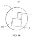
- FIG. 4a and FIG. 4b are schematic diagrams of structures of a microphone-loudspeaker combined module according to an example not covered by the claims.
- FIG. 4a is a schematic diagram of a structure of a microphone-loudspeaker combined module 10 from a first perspective.
- FIG. 4b is a schematic diagram of a structure of a microphone-loudspeaker combined module 10 from a second perspective.
- the microphone-loudspeaker combined module includes a loudspeaker 2, a microphone 3, and a PCB 4.
- the loudspeaker 2 and the microphone 3 are fastened to the PCB 4 separately.
- a signal processing unit for processing an electrical signal for example, a signal processing chip, is disposed on the PCB 4.
- the loudspeaker 2 and the microphone 3 are electrically connected to the signal processing chip by using the PCB 4 separately.
- the signal processing unit may include a first signal processing unit and a second signal processing unit, for example, a first signal processing chip 41 and a second signal processing chip 42.
- the loudspeaker 2 and the microphone 3 are electrically connected to the first signal processing chip 41 by using the PCB 4 separately, and the first signal processing chip 41 is electrically connected to the second signal processing chip 42 by using the PCB 4.
- a first through hole 43 communicating with the loudspeaker 2 is further disposed on the PCB 4, to ensure a pressure balance between a loudspeaker rear cavity and the environment (for a specific process, refer to the description in FIG. 9 ).
- both the loudspeaker 2 and the microphone 3 are made by using a MEMS (Micro-Electro-Mechanical System, micro-electro-mechanical system) process.
- MEMS Micro-Electro-Mechanical System, micro-electro-mechanical system
- the loudspeaker 2 and the microphone 3 made by using the MEMS process have advantages such as a small size, light weight, low power consumption, high reliability, high sensitivity, and easy integration, thereby facilitating integration of the loudspeaker 2 and the microphone 3.
- FIG. 5 is a schematic diagram of communication between the loudspeaker 2, the microphone 3, and the signal processing chip that are shown in FIG. 4a and FIG. 4b .
- a microphone driving module 411, a signal processing module 412, and a loudspeaker driving module 413 are integrated in the first signal processing chip 41.
- the microphone driving module 411 is electrically connected to the microphone 3, and configured to receive an electrical signal sent by the microphone 3 (because the microphone 3 may be piezoelectric, noise may be converted into an electrical signal by the microphone 3).
- the microphone driving module 411 is electrically connected to the signal processing module 412, and the signal processing module 412 can process the electrical signal sent by the microphone driving module 411 (including, for example, matching output impedance of the microphone 3).
- the signal processing module 412 is electrically connected to the second signal processing chip 42, and the second signal processing chip 42 reversely processes the electrical signal sent by the signal processing module 412.
- the loudspeaker driving module 413 is electrically connected to the second signal processing chip 42 and the loudspeaker 2 separately.
- the loudspeaker driving module 413 is configured to transmit the electrical signal sent by the second signal processing chip 42 to the loudspeaker 2.
- the loudspeaker 2 is configured to convert the electrical signal sent by the loudspeaker driving module 413 into a sound signal for sending, to implement active noise cancellation.
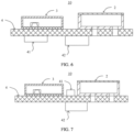
- FIG. 6 is a schematic diagram of a cross section of the microphone-loudspeaker combined module 10 shown in FIG. 4a and FIG. 4b .
- the loudspeaker 2 and the microphone 3 may be located on a second side of the PCB 4
- the first signal processing chip 41 and the second signal processing chip 42 may be located on a first side of the PCB 4.
- FIG. 7 is another schematic diagram of a cross section of the microphone-loudspeaker combined module 10 shown in FIG. 4a and FIG. 4b .
- the loudspeaker 2, the microphone 3, and the first signal processing chip 41 may be located on a second side of the PCB 4, and the second signal processing chip 42 may be located on a first side of the PCB 4.
- the microphone 3 and the loudspeaker 2 are disposed separately, to be specific, are independently and differently disposed perpendicularly to a sound output direction, to improve space utilization of the microphone 3 and the loudspeaker 2.
- the first signal processing chip 41 is electrically connected to the loudspeaker 2 and the microphone 3 separately, whether the first signal processing chip 41 is located on a same side or on an opposite side of the loudspeaker 2 and the microphone 3 is not specifically limited in this application.
- an electrical signal and/or transmission of an electrical signal may be completed by using the PCB 4.
- FIG. 8 is a schematic diagram of a structure for matching between the microphone 3 and the PCB.
- the microphone 3 includes a housing 31, a first membrane 32, and a first substrate 33 for supporting the first membrane 32.
- the housing 31 and the first substrate 33 are fastened to a first PCB 401.
- the housing 31 is fastened to the first substrate 33, and the first substrate 33 is fastened to the first PCB 401.
- the housing 31 is fastened to the first PCB 401, and the first substrate 33 is fastened to the first PCB 401, for example, by welding.
- the microphone 3 is fastened to the PCB 4 by using the first PCB 401, for example, by soldering.
- the first membrane 32 and the first substrate 33 may be integrally etched with a monocrystalline or polycrystalline silicon material. Then a piezoelectric material (for example, a ceramic material) is sprayed on the etched first membrane 32, or a piezoelectric ceramic sheet is covered on the etched first membrane 32, to produce a piezoelectric microphone.
- a piezoelectric material for example, a ceramic material
- a microphone front cavity 34 is formed among the housing 31, the first membrane 32, the first substrate 33, and the first PCB 401, and a microphone rear cavity 35 is formed among the first membrane 32, the first substrate 33, and the first PCB 401.
- a sound port 311 communicating with the microphone front cavity 34 is disposed on the housing 31. A sound is transferred to the first membrane 32 of the microphone 3 through the sound port 311, so that the first membrane 32 is bent with a change in pressure.
- the first membrane 32 and the first substrate 33 may be made of a monocrystalline or polycrystalline silicon material. Then a piezoelectric material (for example, a ceramic material) is sprayed on the first membrane 32, or a piezoelectric ceramic sheet is covered on the etched first membrane 32. When the first membrane 32 is bent, the first membrane 32 generates an electrical signal.
- the first signal processing chip 41 electrically connected to the microphone 3 may process such electrical signals.
- the electrical signal is transferred by using the first substrate 33, the first PCB 401, and the PCB 4. This way is simpler and more convenient, without using a wire connection or providing a channel for a wire to pass on the housing 31.
- the first signal processing chip 41 and the microphone 3 may be electronically connected by using a wire.
- the housing 31 is disposed in an approximately quadrangular prism shape with a rectangular top.
- the housing 31 may be made of metal (choices of metal materials may include stainless steel, aluminum, aluminum alloy, copper, copper alloy, iron, iron alloy, and the like), plastics (choices of plastics may include hard plastics such as ABS, POM, PS, PMMA, PC, PET, PBT, and PPO) and other alloy materials. In this way, arrangement stability of the housing 31 can be improved, thereby effectively improving practicability, reliability, and durability of the housing 31.
- the housing 31 may be made of a metal material, so that an electromagnetic shielding effect of the microphone 3 is more remarkable, thereby improving an electromagnetic anti-interference capability of the microphone 3.
- external noise enters the headset from the sound output hole 13 (refer to FIG. 3 ), and is picked up by the microphone 3.
- the microphone 3 converts the picked-up noise signal into an electrical signal.
- the electrical signal is processed by the first signal processing chip 41 and then sent to the second signal processing chip 42.
- the second signal processing chip 42 reversely processes the noise electrical signal, and then transmits the noise electrical signal to the loudspeaker 2 by using the first signal processing chip 41.
- the loudspeaker 2 outputs a sound signal opposite to the noise according to the reverse noise electrical signal transmitted from the first signal processing chip 41.
- the sound signal opposite to the noise cancels out the noise directly entering the ear, thus providing a good noise cancellation effect.
- FIG. 9 is a schematic diagram of a structure for matching between the loudspeaker 2 and the PCB 4.
- the loudspeaker 2 includes a second membrane 21 and a second substrate 22 for supporting the second membrane 21, and the second substrate 22 is fastened to the PCB 4, for example, by welding.
- the second substrate 22 includes a bottom wall 221 and a side wall 222.
- a loudspeaker rear cavity 23 is formed among the second membrane 21, the bottom wall 221, and the side wall 222 (or between the second membrane 21 and the second substrate 22).
- a loudspeaker front cavity 24 is formed on a side of the second membrane 21 opposite to the loudspeaker rear cavity 23.
- the loudspeaker front cavity 24 communicates with the microphone front cavity 34 (refer to FIG. 8 ), so that the microphone 3 and the loudspeaker 2 can share the front cavity, thereby improving space utilization of the microphone 3 and the loudspeaker 2, and resolving a problem that the loudspeaker and the microphone occupy a large space.
- the second membrane 21 and the second substrate 22 may be integrally etched by using a monocrystalline or polycrystalline silicon material. Then a piezoelectric material (for example, a ceramic material) is sprayed on the etched second membrane 21, or a piezoelectric ceramic sheet is covered on the etched first membrane 32. Therefore, the first signal processing chip 41 electrically connected to the loudspeaker 2 can excite the second membrane 21, so that the second membrane 21 vibrates relative to the second substrate 22 to make a sound. To be specific, the loudspeaker 2 can first convert an electrical signal into a mechanical deformation, and then convert the mechanical deformation into a sound signal, to make a sound.
- a piezoelectric material for example, a ceramic material
- one or more second through holes 223 communicating with the first through hole 43 are disposed on the bottom wall 221.
- the first through hole 43 extends through a first side 441 and a second side 442 of the PCB 4.
- air may flow from the loudspeaker rear cavity 23, through the second through hole 223 and the first through hole 43, to the outside of the first side 441 of the PCB 4 (because the first side 441 of the PCB 4 communicates with the environment).
- air may flow from the outside of the first side 441 of the PCB 4, through the first through hole 43 and the second through hole 223, into the loudspeaker rear cavity 23.
- FIG. 10 is another schematic diagram of a structure for matching between a loudspeaker 2 and a PCB 4, and FIG. 11 is a top view of a second membrane 21 of the loudspeaker 2 shown in FIG. 10 .
- the loudspeaker 2 differs from the loudspeaker 2 shown in FIG. 9 in that one end of the second membrane 21 is fastened to the side wall 222 and another end is a free end (a cantilever structure).
- a gap 211 is provided between two adjacent second membranes 21, to facilitate vibration of each second membrane 21.
- the loudspeaker 2 is configured to make a sound
- the microphone 3 is mainly configured to pick up external noise. Therefore, vibration amplitude of the second membrane 21 may be greater than that of the first membrane 32.
- bending amplitude of the second membrane 21 using the structure shown in FIG. 10 and FIG. 11 is greater than that of the second membrane 21 using the structure shown in FIG. 9 , so that the second membrane 21 makes a larger range of sounds.
- the second membranes 21 are sector structures with a same cross-sectional area, and there may be six second membranes 21, to fill the circular region to a greater extent.
- the circular region may be in another shape, for example, a rectangle.
- the second membrane 21 may be a triangular structure, and there may be four second membranes 21, to fill the rectangular region to a greater extent.
- the microphone 3 is fastened to the PCB 4 by using the first PCB 401, specifically, in an SMT patch manner.
- the first signal processing chip 41 and the loudspeaker 2 may also be fastened to the PCB 4 in an SMT patch manner, thereby resolving a problem of sound effect inconsistency caused by a difference in manually assembled modules of the entire machine, and improving product reliability.
- the loudspeaker 2 can also be fastened in an SMT patch manner.
- the loudspeaker is fastened to the PCB in a common welding or bonding manner because a membrane of a microphone in the related technology is made of a material, for example, PET, PEN, or PEI.
- the material is not high temperature resistant, and therefore, an SMT patch process may not be used.
- both the first membrane 32 and the second membrane 21 are made of a piezoelectric material (for example, a ceramic material), thereby improving waterproof and dustproof capabilities of the headset.
- the loudspeaker 2 and the microphone 3 provided in this example can pick up a sound and make a sound separately by using a characteristic of the piezoelectric material, without generating a coupling noise between the loudspeaker 2 and the microphone 3, thereby resolving a problem of electrical signal interference generated by a close-range combination of the conventional moving coil loudspeaker and the microphone.
- FIG. 12a and FIG. 12b are schematic diagrams of structures of a microphone-loudspeaker combined module 10 according to Embodiment 1 of this application.
- FIG. 12a is a schematic diagram of a structure of the microphone-loudspeaker combined module 10 from a first perspective.
- FIG. 12b is a schematic diagram of a structure of the microphone-loudspeaker combined module 10 from a second perspective.
- a difference between the microphone-loudspeaker combined modules 10 shown in this embodiment and in Embodiment 1 lies in that the loudspeaker 2 and the microphone 3 are integrated into one component (referred to as "a first integrated body").
- FIG. 13a and FIG. 13b are schematic diagrams of structures when the loudspeaker 2 and the microphone 3 are integrated into the first integrated body.
- FIG. 13a is a schematic diagram of a structure of the first integrated body from a first perspective.
- FIG. 13b is a schematic diagram of a structure of the first integrated body from a second perspective.
- the first integrated body includes a first bottom wall 201, a first side wall 202 and a second side wall 203 (refer to FIG. 14a ) separately connected to the first bottom wall 201, a first membrane 32, and a second membrane 21.
- the first side wall 202 is disposed on the first bottom wall 201 to form a cavity.
- the second side wall 203 is disposed on the first bottom wall 201.
- the second side wall 203 is located inside the first side wall 202.
- the second side wall 203 is connected to the first side wall 202 to form a cavity.
- the quantity of the first membrane 32 and the second membrane 21 shown in FIG. 13a is merely an example. It may be understood that the first integrated body has at least one first membrane 32 and at least one second membrane 21.
- FIG. 14a is a schematic diagram of a partial structure of the microphone 3 in FIG. 13a .
- FIG. 14b is a schematic diagram of a partial structure of the loudspeaker 2 in FIG. 13a .
- the first side wall 202 is disposed outside the second side wall 203 and is connected to the second side wall 203.
- the first membrane 32 is fastened to the first side wall 202 and the second side wall 203.
- One end of the second membrane 21 is fastened to the first side wall 202 and another end is a free end (a cantilever structure).
- a microphone rear cavity is formed among the first bottom wall 201, the first side wall 202, the second side wall 203, and the first membrane 32, and a microphone front cavity is formed on a side of the first membrane 32 opposite to the microphone rear cavity.
- a loudspeaker rear cavity is formed among the first bottom wall 201, the first side wall 202, the second side wall 203, and the second membrane 21, and a loudspeaker front cavity is formed on a side of the second membrane 21 opposite to the loudspeaker rear cavity. Because vibration amplitude of the second membrane 21 may be greater than that of the first membrane 32, a pressure change caused by vibration of the second membrane 21 is also remarkable.
- a second through hole 223 communicating with the first through hole 43 is disposed on the first bottom wall 201.
- first bottom wall 201 and the first side wall 202 and the second side wall 203 that are separately connected to the first bottom wall 201 may be made of a monocrystalline or polycrystalline silicon material, to transfer an electrical signal generated by the first membrane 32 to the PCB 4, or transfer an electrical signal received from the PCB 4 to the second membrane 21.
- the first bottom wall 201 may be a circular structure (refer to FIG. 13b ), the first side wall 202 may be a cylindrical cavity (refer to FIG. 13a ), and the second side wall 203 may be a folded-line structure.
- the second side wall 203 and the first side wall 202 form a sector cavity (refer to FIG. 14a ).
- the first membrane 32 formed on the first side wall 202 and the second side wall 203 may be a sector structure (refer to FIG. 13a and FIG. 14a ).
- the second membrane 21 formed on the first side wall 202 may be a sector structure (refer to FIG. 13a and FIG. 14b ).
- a total quantity of the first membrane 32 and the second membrane 21 may be six, to evenly divide the circle into six sector structures.
- first bottom wall 201 may be alternatively a square structure or a structure of another shape.
- Specific shapes of the first side wall 202, the second side wall 203, the first membrane 32, and the second membrane 21 may be correspondingly designed according to the specific shape of the first bottom wall 201. This is not specifically limited in this application.
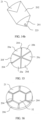
- FIG. 15 is a schematic diagram of a structure of the first membrane 32 and the second membrane 21 shown in FIG. 13a .
- the six sector structures are defined as: a first sector structure 20a, a second sector structure 20b, a third sector structure 20c, a fourth sector structure 20d, a fifth sector structure 20e, and a sixth sector structure 20f.
- the combination of forming the first membrane 32 and the second membrane 21 may be as follows: The first sector structure 20a is the first membrane 32, and the remaining sector structures are the second membrane 21.
- the first sector structure 20a and the fourth sector structure 20d are the first membrane 32, and the remaining sector structures are the second membrane 21.
- the first sector structure 20a, the third sector structure 20c, and the fifth sector structure 20e are the first membrane 32, and the remaining sector structures are the second membrane 21.
- the first sector structure 20a and the second sector structure 20b are the first membrane 32, and the remaining sector structures are the second membrane 21.
- the microphone 3 and the loudspeaker 2 are disposed integrally. Compared with separate arrangement of the microphone 3 and the loudspeaker 2, this integral arrangement can further improve space utilization of the microphone 3 and the loudspeaker 2.
- FIG. 16 is a schematic diagram of a structure when the loudspeaker 2 and the microphone 3 are integrated into a second integrated body.
- FIG. 17 is a schematic diagram of a cross section of the second integrated body.
- FIG. 18 is a schematic diagram of another cross section of the second integrated body. Refer to FIG. 16 to FIG. 18 .
- the second integrated body includes a second bottom wall 205, a third side wall 206 and a fourth side wall 207 that are separately connected to the second bottom wall 205, a first membrane 32, and a second membrane 21.
- the third side wall 206 is disposed on the second bottom wall 205 to form a cavity.
- the fourth side wall 207 is disposed on the second bottom wall 205 to form a cavity.
- the fourth side wall 207 is located inside the third side wall 206.
- One end of the second membrane 21 is fastened to the third side wall 206 and another end is a free end (a cantilever structure).
- the first membrane 32 is fastened to the fourth side wall 207.
- the six second membranes 21 are evenly distributed on the periphery of the first membrane 32.
- gaps 204 are provided between two adjacent second membranes 21, and between the first membrane 32 and the second membrane 21.
- the second bottom wall 205 may be a circular structure
- the third side wall 206 may be a cylindrical cavity
- the fourth side wall 207 may be a polyhedral (for example, hexahedral) cavity.
- the first membrane 32 formed on the fourth side wall 207 may be a polygonal (for example, hexagonal) structure
- the second membrane 21 formed on the third side wall 206 may be a trapecio-circular-like (for example, an edge of a trapecio circular close to the first membrane 32 is changed from a curve to a straight line) structure.
- the second bottom wall 205 may be a circular structure
- the third side wall 206 may be a cylindrical cavity
- the fourth side wall 207 may be a cylindrical cavity
- the first membrane 32 formed on the fourth side wall 207 may be a circular structure
- the second membrane 21 formed on the third side wall 206 may be a trapecio circular structure.
- a microphone rear cavity is formed among the second bottom wall 205, the fourth side wall 207, and the first membrane 32, and a microphone front cavity is formed on a side of the first membrane 32 opposite to the microphone rear cavity.
- a loudspeaker rear cavity is formed among the second bottom wall 205, the third side wall 206, the fourth side wall 207, and the second membrane 21, and a loudspeaker front cavity is formed on a side of the second membrane 21 opposite to the loudspeaker rear cavity.
- the first membrane 32 is disposed at the center of the second integrated body. Because the microphone 3 of the headset is mainly configured to pick up external noise and the main purpose of the headset is to enable the loudspeaker 2 to make a sound, a cross-sectional area of the second membrane 21 of the loudspeaker 2 needs to be greater than that of the first membrane 32 of the microphone 3.
- the microphone 3 and the loudspeaker 2 are disposed integrally. Compared with separate arrangement of the microphone 3 and the loudspeaker 2, this integral arrangement can further improve space utilization of the microphone 3 and the loudspeaker 2.
- FIG. 19 is a schematic diagram of a cross section of the microphone-loudspeaker combined module 10 shown in FIG. 12a and FIG. 12b .
- the loudspeaker 2 and the microphone 3 in FIG. 19 are shown as the second integrated body shown in FIG. 16 .
- the second integrated body is disposed on a second side 442 of the PCB 4, and a first signal processing chip 41 and a second signal processing chip 42 are disposed on a first side 441 of the PCB 4.
- the first signal processing chip 41 and the second signal processing chip 42 may be disposed separately.
- FIG. 20 is another schematic diagram of a cross section of the microphone-loudspeaker combined module 10 shown in FIG. 12a and FIG. 12b .
- the loudspeaker 2 and the microphone 3 in FIG. 20 are shown as the second integrated body shown in FIG. 16 .
- the second integrated body is disposed on a second side 442 of the PCB 4, and a first signal processing chip 41 and a second signal processing chip 42 are disposed on a first side 441 of the PCB 4.
- the first signal processing chip 41 and the second signal processing chip 42 may be integrally disposed onto a cover 40.
- the first signal processing chip 41 and the second signal processing chip 42 may be encapsulated in the cover 40 in a SIP (System in Package, system-in-package) encapsulation manner.
- SIP System in Package, system-in-package
- the microphone-loudspeaker combined module 10 shown in FIG. 6 and FIG. 7 may also use a SIP encapsulation manner.
- SIP encapsulation may be performed on the first signal processing chip 41 and the second signal processing chip 42 in the microphone-loudspeaker combined module 10 shown in FIG. 6 , or the microphone 3 and the loudspeaker 2 may be encapsulated.
- SIP encapsulation may be performed on the microphone 3, the loudspeaker 2, and the first signal processing chip 41 in the microphone-loudspeaker combined module 10 shown in FIG. 7 .
- external noise enters the headset from the sound output hole 13 (refer to FIG. 3 ) and is picked up by the microphone 3, to cause the first membrane 32 to bend with a change in pressure.
- an electrical signal is generated.
- the generated electrical signal is transmitted to the PCB 4 by using the second side wall 203 and the first bottom wall 201 (or using the fourth side wall 207 and the second bottom wall 205), and then to the first signal processing chip 41 on the PCB 4.
- the first signal processing chip 41 processes the electrical signal and transmits the processed electrical signal to the second signal processing chip 42 for reverse processing.
- the reversely processed electrical signal is transmitted to the PCB 4, the first bottom wall 201, the first side wall 202, and the second membrane 21 (or to the PCB 4, the second bottom wall 205, the third side wall 206, and the second membrane 21) by using the first signal processing chip 41.
- the second membrane 21 outputs a sound signal opposite to the noise according to the reverse noise electrical signal transmitted from the first signal processing chip 41.
- the sound signal opposite to the noise cancels out the noise directly entering the car, thereby fulfilling a good noise cancellation function.
- FIG. 21a and FIG. 21b are schematic diagrams of structures of a microphone-loudspeaker combined module 10 according to Embodiment 2 of this application.
- FIG. 21a is a schematic diagram of a structure of the microphone-loudspeaker combined module 10 from a first perspective.
- FIG. 21b is a schematic diagram of a structure of the microphone-loudspeaker combined module 10 from a second perspective.
- a difference between the microphone-loudspeaker combined modules 10 shown in this embodiment and in Embodiment 1 lies in that the loudspeaker 2, the microphone 3, and the first signal processing chip 41 are integrated into one component. Specifically, in this embodiment, the loudspeaker 2, the microphone 3, and the first signal processing chip 41 are all located on a second side of the PCB 4.
- the loudspeaker 2 and the microphone 3 in Embodiment 2 are electrically connected to the first signal processing chip 41 after being integrated into the first integrated body or the second integrated body.
- FIG. 22 is a schematic diagram of a cross section of the microphone-loudspeaker combined module 10 shown in FIG. 21a and FIG. 21b.
- FIG. 22 shows a location relationship between the first signal processing chip 41 and the second integrated body integrated by the loudspeaker 2 and the microphone 3.
- the loudspeaker 2, the microphone 3, and the first signal processing chip 41 are all located on a second side of the PCB 4.
- FIG. 23 is another schematic diagram of a cross section of the microphone-loudspeaker combined module 10 shown in FIG. 21a and FIG. 21b .
- FIG. 23 shows a location relationship between the first signal processing chip 41 and the second integrated body integrated by the loudspeaker 2 and the microphone 3.
- the loudspeaker 2, the microphone 3, and the first signal processing chip 41 are all located on a second side of the PCB 4.
- the microphone-loudspeaker combined module 10 shown in FIG. 23 implements SIP encapsulation of the microphone 3, the loudspeaker 2, and the first signal processing chip 41.
- a third through hole 40a communicating with the microphone-loudspeaker combined module 10 needs to be provided on the cover 40, so that air flows into or out of the cover 40 through the third through hole 40a.
- an integration manner of the loudspeaker 2 and the microphone 3 (a manner of integrating into the first integrated body or the second integrated body) is consistent with that in Embodiment 1, and details are not described herein again.
- the loudspeaker 2 and the microphone 3 are integrated into one part: the first integrated body or the second integrated body. Compared with that in Embodiment 1, this integral arrangement can increase a volume of the loudspeaker front cavity. Therefore, favorable conditions can be further provided for functions such as sound pickup in the ear canal, active noise cancellation, and uplink noise cancellation.
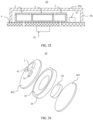
- FIG. 24 is a schematic exploded view of a microphone-loudspeaker combined module 10 according to another example.
- a PCB 4 includes a second PCB 402 and a third PCB 403.
- the microphone-loudspeaker combined module 10 includes a loudspeaker 2, a microphone 3, a signal processing unit, the second PCB 402, and the third PCB 403.
- the signal processing unit may include a first signal processing unit and a second signal processing unit, for example, a first signal processing chip 41 and a second signal processing chip 42 (the second signal processing chip 42 is not shown in FIG. 22 ).
- the microphone 3 is fastened to the second PCB 402 by using the first PCB 401, and the signal processing unit (for example, the first signal processing chip 41) is fastened to the second PCB 402.
- both the microphone 3 and the signal processing unit are fastened to the second PCB 402 by using an SMT process.
- the loudspeaker 2 is disposed between the second PCB 402 and the third PCB 403, so that the microphone 3 and the loudspeaker 2 are assembled and molded, to be specific, the microphone 3 and the loudspeaker 2 may be independently and differently disposed along a sound output direction.
- the loudspeaker 2 includes a driving system 20, a membrane 25, and a bracket 26.
- the bracket 26 is disposed between the second PCB 402 and the third PCB 403, and functions to protect the loudspeaker 2 and support the membrane 25.
- the bracket 26 may be made of a material, for example, iron, aluminum alloy, or ABS plastic, to ensure good strength.
- the membrane 25 is disposed on the bracket 26, and the second PCB 402 is disposed along a sound output direction of the membrane 25 (in front of the membrane 25).
- the second PCB 402 cannot only integrate the microphone 3 and the first signal processing chip 41, but also protect the membrane 25 because the second PCB 402 is disposed in front of the membrane 25.
- a loudspeaker front cavity is formed between the membrane 25 and the second PCB 402.
- a sound outlet 16 is provided with the second PCB 402.
- the loudspeaker front cavity communicates with a microphone front cavity through the sound outlet 16.
- the sound outlet 16 may also communicate with the front cavity 15 (refer to FIG. 3 ).
- the driving system 20 is provided on the third PCB 403 and configured to drive the membrane 25 to vibrate.
- the driving system 20 may use a moving coil type or a piezoelectric type.
- the driving system 20 is a magnetic circuit system (a specific structure thereof is not shown in the diagram), and a voice coil (not shown in the diagram) of the membrane 25 is inserted into the driving system 20. Since the driving manner may be the conventional technology, a specific composition of the magnetic circuit system and a manner of setting the voice coil and the second membrane 21 are not described herein.
- the driving system 20 uses the piezoelectric type, refer to FIG. 9 or FIG. 10 for a specific structure of the driving system 20.
- the center (the bottom end) of the membrane 25 is attached to the second membrane 21, so that vibration of the second membrane 21 drives the membrane 25 to vibrate to make a sound.
- the sound is sent from the sound outlet 16 disposed at the center of the second PCB 402.
- the second PCB 402 and the third PCB 403 are separately fastened to two ends of the bracket 26, and the driving system 20 is fastened to the third PCB 403.
- the driving system 20 may be fastened to the third PCB 403 by using an SMT process.
- the microphone 3 and the loudspeaker 2 are disposed separately, to be specific, are independently and differently disposed along a sound output direction, to improve space utilization of the microphone 3 and the loudspeaker 2.
- the microphone-loudspeaker combined module 10 is provided in examples and Embodiments 1 to Embodiment 2 of this application.
- the examples show structural forms in which the microphone 3 and the loudspeaker 2 are disposed separately.
- Embodiment 1 and Embodiment 2 show structural forms in which the microphone 3 and the loudspeaker 2 are disposed integrally.
- the loudspeaker 2, the microphone 3, and the signal processing unit are integrated, thereby reducing space occupied by the loudspeaker 2, the microphone 3, and the signal processing unit. Because the loudspeaker 2 is disposed in the front cavity 15, the front cavity 15 is not squeezed, and a cross-sectional area of the acoustic radiation tube is not reduced, thereby improving a high-frequency sound effect of the headset.
Landscapes
- Engineering & Computer Science (AREA)
- Physics & Mathematics (AREA)
- Acoustics & Sound (AREA)
- Signal Processing (AREA)
- Manufacturing & Machinery (AREA)
- Soundproofing, Sound Blocking, And Sound Damping (AREA)
- Electrostatic, Electromagnetic, Magneto- Strictive, And Variable-Resistance Transducers (AREA)
Description
- This application relates to the field of wireless headset technologies, and in particular, to a microphone-loudspeaker combined module, a headset, and a terminal device.
- Development of a TWS (True Wireless Stereo, true wireless stereo) wireless Bluetooth headset technology brings numerous sensors to a TWS headset, resulting in increasingly high integration of headset elements and increasingly deficient space inside the headset.
- To obtain a good uplink call effect and meet a requirement of picking up an ANC (Active Noise Cancellation, active noise cancellation) feedback signal, a microphone is usually disposed between a loudspeaker (also referred to as a horn) and an ear canal. The microphone is configured to pick up a surrounding noise signal and reversely transmit the noise signal to the loudspeaker by using a circuit. The reverse noise signal that is output by the loudspeaker cancels out a noise signal directly entering the ear, to reduce the noise.
-
FIG. 1 is a schematic diagram of a cross section of an existing (noise cancellation) headset. The headset includes a first housing 11' and a second housing 12'. A magnetic circuit system 21' of a loudspeaker 2' is disposed in the first housing 11'. A membrane 22' of the loudspeaker 2' and the second housing 12' form a front cavity 13' of the loudspeaker 2'. The loudspeaker 2' and a microphone 3' are independently disposed components. The microphone 3' is fastened to a PCB (Printed Circuit Board, printed circuit board) 4'. The PCB 4' is disposed outside the second housing 12'. The loudspeaker 2' and the PCB 4' are electrically connected by using an FPC (Flexible Printed Circuit, flexible printed circuit) (not shown in the diagram). The front cavity 13' of the loudspeaker 2' is squeezed due to a way of disposing the microphone 3', and consequently a cross-sectional area of an acoustic radiation tube 131' of the front cavity 13' is reduced, thereby affecting a high-frequency response of the loudspeaker 2' and deteriorating a high-frequency sound effect of the headset. - Therefore, a microphone-loudspeaker combined module, a headset, and a terminal device are in urgent need to resolve the foregoing problem.
-
EP 1 396 983 A1 describes a structural arrangement for a radio communication terminal incorporating a loudspeaker and earpiece. -
WO 2011/061483 A2 describes a production of ambient noise-cancelling earphones. - In view of the problem in the background, an objective of this application is to provide a microphone-loudspeaker combined module, a headset, and a terminal device, to resolve a problem that a loudspeaker and a microphone occupy large space.
- The present invention is defined by the subject-matter of the independent claim 1. Additional features of the invention are presented in the dependent claims.
- According to a first aspect, a technical solution of this application provides a microphone-loudspeaker combo module according to claim 1.
- The microphone and the loudspeaker are disposed integrally. Compared with separate arrangement of the microphone and the loudspeaker, this integral arrangement can further improve space utilization of the microphone and the loudspeaker.
- In a possible design, the microphone and the loudspeaker form a first integrated body, where the first integrated body includes:
- a first bottom wall, disposed on the PCB;
- a first side wall, disposed on the first bottom wall to form a cavity;
- a second side wall, disposed on the first bottom wall, where the second side wall is located inside the first side wall, and the second side wall is connected to the first side wall to form a cavity;
- a first membrane, disposed on the first side wall and the second side wall; and
- a second membrane, where one end thereof is disposed on the first side wall and another end is a free end.
- The microphone rear cavity is formed among the first bottom wall, the first side wall, the second side wall, and the first membrane, the loudspeaker rear cavity is formed among the first bottom wall, the first side wall, the second side wall, and the second membrane, and there is a gap between the first membrane and the second membrane.
- The microphone front cavity is formed on a side of the first membrane opposite to the microphone rear cavity, and the loudspeaker front cavity is formed on a side of the second membrane opposite to the loudspeaker rear cavity. In this way, noise can be picked up by the first membrane and a sound can be made by the second membrane. In addition, because another end of the second membrane is a free end, vibration amplitude of the second membrane is greater than that of the first membrane.
- In a possible design, there is a plurality of first membranes, and there is a gap between two adjacent first membranes, thereby facilitating vibration of the first membrane.
- In a possible design, there is a plurality of second membranes, and there is a gap between two adjacent second membranes, thereby facilitating vibration of the second membrane.
- In a possible design, the microphone and the loudspeaker form a second integrated body, where the second integrated body includes:
- a second bottom wall, disposed on the PCB;
- a third side wall, disposed on the second bottom wall to form a cavity;
- a fourth side wall, disposed on the second bottom wall to form a cavity, where the fourth side wall is located inside the third side wall;
- a first membrane, disposed on the fourth side wall; and
- a second membrane, with one end disposed on the third side wall and another end is a free end.
- The microphone rear cavity is formed among the second bottom wall, the fourth side wall, and the first membrane, the loudspeaker rear cavity is formed among the second bottom wall, the third side wall, the fourth side wall, and the second membrane, and there is a gap between the first membrane and the second membrane.
- The microphone front cavity is formed on a side of the first membrane opposite to the microphone rear cavity, and the loudspeaker front cavity is formed on a side of the second membrane opposite to the loudspeaker rear cavity. In this way, noise can be picked up by the first membrane and a sound can be made by the second membrane. In addition, because another end of the second membrane is a free end, vibration amplitude of the second membrane is greater than that of the first membrane.
- In a possible design, there is one first membrane disposed at the center of the second integrated body. Considering that the microphone of the headset is mainly configured to pick up external noise, a cross-sectional area of the first membrane does not need to be very large, for example, the first membrane may be at the center of the second integrated body.
- In a possible design, there is a plurality of second membranes, and there is a gap between two adjacent second membranes, thereby facilitating vibration of the second membrane.
- In a possible design, the microphone and the loudspeaker are made by using a MEMS process, thereby facilitating integration of the microphone and the loudspeaker.
- In a possible design, the microphone, the loudspeaker, and the signal processing unit are fastened to the PCB by using an SMT process, thereby resolving a problem of sound effect inconsistency caused by a difference in manually assembled modules of the entire machine, and improving product reliability.
- In a possible design, the signal processing unit includes:
- a first signal processing unit, electrically connected to the microphone and the loudspeaker separately; and
- a second signal processing unit, electrically connected to the first signal processing unit. The first signal processing unit can match output impedance of the microphone and achieve a more balanced effect for call and audio quality. The second signal processing unit can reversely process an electrical signal of noise to implement active noise cancellation.
- In a possible design, the first signal processing unit includes an ASIC chip, and the second signal processing unit includes a DSP chip. The ASIC chip is used to drive the microphone and the loudspeaker, and the DSP chip is used to reversely process an electrical signal of noise.
- In a possible design, a first through hole is disposed on the PCB, a second through hole is disposed on the loudspeaker, and the first through hole communicates with the second through hole, to ensure a pressure balance between the loudspeaker rear cavity and the environment.
- According to a second aspect, a technical solution of this application provides a headset, including:
- a first housing;
- a second housing, connected to the first housing; and
- a microphone-loudspeaker combined module, disposed between the first housing and the second housing, where the microphone-loudspeaker combined module is the microphone-loudspeaker combined module described above.
- A rear cavity of the microphone and the loudspeaker is formed between the first housing and the PCB, and a front cavity of the microphone and the loudspeaker is formed between the second housing and the PCB. In this way, the microphone and the loudspeaker can share the front cavity, thereby improving space utilization of the microphone and the loudspeaker.
- In a possible design, the second housing includes an ear-in part, a sound output hole is disposed in the ear-in part, the sound output hole communicates with the front cavity, and a damping net is disposed in the ear-in part. A high-frequency sound made by the loudspeaker can be filtered out by setting the damping net, thereby making a bass effect of the headset more remarkable.
- In a possible design, the second housing further includes a first stepped part connected to the ear-in part, and the loudspeaker and the microphone are disposed in an internal cavity of the first stepped part; and
an inner diameter of the first stepped part is greater than that of the ear-in part, to increase a volume of the front cavity to a maximum extent. - In a possible design, the second housing further includes a second stepped part connected to the first stepped part, and the second stepped part is fastened to the first housing; and
an inner diameter of the second stepped part is greater than that of the first stepped part, a step is disposed in the second stepped part, and the PCB is fastened to the step, to accommodate the microphone-loudspeaker combined module. - According to a third aspect, a technical solution of this application provides a terminal device, including the microphone-loudspeaker combined module described above, to reduce space occupied by the microphone and the loudspeaker on the terminal device.
- It can be learned that, in the foregoing aspects, the microphone front cavity of the microphone communicates with the loudspeaker front cavity of the loudspeaker, so that the microphone and the loudspeaker can share the front cavity, thereby improving space utilization of the microphone and the loudspeaker, and resolving a problem that the loudspeaker and the microphone occupy large space.
-
-
FIG. 1 is a schematic diagram of a cross section of an existing (noise cancellation) headset; -
FIG. 2 is a schematic exploded view of a headset according to an embodiment of this application; -
FIG. 3 is a schematic diagram of a cross section of a headset according to an embodiment of this application; -
FIG. 4a andFIG. 4b are schematic diagrams of structures of a microphone-loudspeaker combined module according to an example not covered by the claims; -
FIG. 5 is a schematic diagram of communication between a loudspeaker, a microphone, and a signal processing chip that are shown inFIG. 4a andFIG. 4b ; -
FIG. 6 is a schematic diagram of a cross section of the microphone-loudspeaker combined module shown inFIG. 4a andFIG. 4b ; -
FIG. 7 is another schematic diagram of a cross section of the microphone-loudspeaker combinedmodule 10 shown inFIG. 4a andFIG. 4b ; -
FIG. 8 is a schematic diagram of a structure for matching between a microphone and a PCB; -
FIG. 9 is a schematic diagram of a structure for matching between a loudspeaker and a PCB; -
FIG. 10 is another schematic diagram of a structure for matching between a loudspeaker and a PCB; -
FIG. 11 is a top view of a second membrane of the loudspeaker shown inFIG. 10 ; -
FIG. 12a and FIG. 12b are schematic diagrams of structures of a microphone-loudspeaker combined module according to Embodiment 1 of this application; -
FIG. 13a and FIG. 13b are schematic diagrams of structures when a loudspeaker and a microphone are integrated into a first integrated body; -
FIG. 14a is a schematic diagram of a partial structure of the microphone shown inFIG. 13a ; -
FIG. 14b is a schematic diagram of a partial structure of the loudspeaker shown inFIG. 13a ; -
FIG. 15 is a schematic diagram of structures of a first membrane and a second membrane shown inFIG. 13a ; -
FIG. 16 is a schematic diagram of a structure when a loudspeaker and a microphone are integrated into a second integrated body; -
FIG. 17 is a schematic diagram of a cross section of a second integrated body; -
FIG. 18 is a schematic diagram of another cross section of a second integrated body; -
FIG. 19 is a schematic diagram of a cross section of the microphone-loudspeaker combined module shown inFIG. 12a and FIG. 12b ; -
FIG. 20 is another schematic diagram of a cross section of the microphone-loudspeaker combined module shown inFIG. 12a and FIG. 12b ; -
FIG. 21a andFIG. 21b are schematic diagrams of structures of a microphone-loudspeaker combined module according toEmbodiment 2 of this application; -
FIG. 22 is a schematic diagram of a cross section of the microphone-loudspeaker combinedmodule 10 shown inFIG. 21a andFIG. 21b ; -
FIG. 23 is another schematic diagram of a cross section of the microphone-loudspeaker combinedmodule 10 shown inFIG. 21a andFIG. 21b ; and -
FIG. 24 is a schematic exploded view of a microphone-loudspeaker combinedmodule 10 according to another example not covered by the claims. -
- 11'-first housing;
- 12'-second housing;
- 13'-front cavity;
131'- acoustic radiation tube; - 2'-loudspeaker;
- 21'-magnetic circuit system;
- 22'- membrane;
- 3'-microphone;
- 4'-PCB;
- 10- microphone-loudspeaker combined module;
- 11-first housing;
- 12-second housing;
- 121-ear-in part;
- 122-first stepped part;
- 123-second stepped part;
123a-step; - 124-damping net;
- 13-sound output hole;
- 14-rear cavity;
- 15-front cavity;
- 16-sound outlet;
- 2-loudspeaker;
- 20-driving system;
- 21-second membrane;
211-gap; - 22-second substrate;
- 221-bottom wall;
- 222-side wall;
- 223-second through hole;
- 23-loudspeaker rear cavity;
- 24-loudspeaker front cavity;
- 25-membrane;
- 201-first bottom wall;
- 202-first side wall;
- 203-second side wall;
- 204-gap;
- 205-second bottom wall;
- 206-third side wall;
- 207-fourth side wall;
- 20a- first sector structure;
- 20b-second sector structure;
- 20c-third sector structure;
- 20d-fourth sector structure;
- 20e-fifth sector structure;
- 20f-sixth sector structure;
- 3-microphone;
- 31-housing;
311-sound port; - 32-first membrane;
- 33-first substrate;
- 34-microphone front cavity;
- 35-microphone rear cavity;
- 31-housing;
- 4-PCB;
- 40-cover;
40a-third through hole; - 41-first signal processing chip;
- 42-second signal processing chip;
- 43-first through hole;
- 441-first side;
- 442-second side;
- 401-first PCB;
- 402-second PCB;
- 403-third PCB.
- 40-cover;
- The accompanying drawings herein are incorporated into the specification and form a part of the specification, show embodiments conforming to this application, and are used together with the specification to explain a principle of this application.
- To better understand the technical solutions of this application, the following describes embodiments of this application in detail with reference to the accompanying drawings.
- The terms used in embodiments of this application are merely for the purpose of illustrating specific embodiments, and are not intended to limit this application. The terms "a", "the" and "this" of singular forms used in the embodiments and the appended claims of this application are also intended to include plural forms, unless otherwise specified in the context clearly.
- It should be understood that the term "and/or" in this specification describes only an association relationship for describing associated objects and represents that three relationships may exist. For example, A and/or B may represent the following three cases: Only A exists, both A and B exist, and only B exists. In addition, the character "/" in this specification generally indicates an "or" relationship between the associated objects.
- It should be noted that, position words such as "above", "below", "left", and "right" described in embodiments of this application are described from angles shown in the accompanying drawings, and should not be construed as a limitation on embodiments of this application. Moreover, in the context, it also should be understood that, when it is mentioned that one element is connected "above" or "below" another element, it cannot only be directly connected "above" or "below" the another element, but also be indirectly connected "above" or "below" the another element by using an intermediate element.
- In a related technology, some terminal devices have functions of picking up a sound and making a sound, in other words, have acoustic components such as a microphone and a loudspeaker. However, these acoustic components are independently disposed components on the terminal device, and occupy large internal space of the terminal device.
- To resolve the foregoing technical problem, an embodiment of this application provides a terminal device. A microphone-loudspeaker combined module is disposed on the terminal device. The microphone-loudspeaker combined module can integrate a microphone and a loudspeaker on a PCB, to reduce space occupied by the microphone and the loudspeaker. The terminal device may be, for example, a head-mounted device (specifically AR glasses or VR glasses); or may be, for example, a portable device (specifically a headset, a mobile phone, or a wristband); or may be certainly another product having a sound pickup function and a sound making function, and enumeration is not performed herein.
- For example, the terminal device may be a headset. In an implementation solution, the headset may be a TWS (True Wireless Stereo, true wireless stereo) wireless Bluetooth headset.
-
FIG. 2 is a schematic exploded view of a headset according to an embodiment of this application. The headset includes afirst housing 11 and asecond housing 12. Space for accommodating a microphone-loudspeaker combinedmodule 10 is formed between thefirst housing 11 and thesecond housing 12. The microphone-loudspeaker combinedmodule 10 includes aloudspeaker 2, amicrophone 3, and aPCB 4. Theloudspeaker 2 and themicrophone 3 are fastened to thePCB 4. A signal processing unit configured to process an electrical signal, for example, a signal processing chip, may be further disposed on thePCB 4. Theloudspeaker 2 and themicrophone 3 are electrically connected to the signal processing unit by using thePCB 4 separately. In an implementation, the signal processing unit may include a first signal processing unit and a second signal processing unit. For example, the first signal processing unit is a firstsignal processing chip 41, and the second signal processing unit is a secondsignal processing chip 42. Theloudspeaker 2 and themicrophone 3 are electrically connected to the firstsignal processing chip 41 by using thePCB 4 separately, and the firstsignal processing chip 41 is electrically connected to the secondsignal processing chip 42 by using thePCB 4. The first signal processing unit can match output impedance of themicrophone 3 and achieve a more balanced effect for call and audio quality. The second signal processing unit can reversely process an electrical signal of noise to implement active noise cancellation. For a detailed working process, refer to the following description. - In some implementations, the
loudspeaker 2, themicrophone 3, the firstsignal processing chip 41, and the secondsignal processing chip 42 are all welded on thePCB 4, for example, by using an SMT (Surface Mount Technology, surface mount technology). - In some implementations, the first
signal processing chip 41 includes but is not limited to an ASIC (Application-Specific Integrated Circuit, application-specific integrated circuit) chip, and may further include, for example, an FPGA (Field Programmable Gate Array, field programmable gate array) chip or a DSP (Digital Signal Processor, digital signal processor) chip. - In some implementations, the second
signal processing chip 42 includes but is not limited to a DSP chip, and may further include, for example, an FPGA chip, or a BT SOC (Bluetooth System on Chip, Bluetooth system on chip, in other words, Bluetooth chip) integrated with a DSP chip (or an FPGA chip). - It should be noted that, by using an example in which the first
signal processing chip 41 includes an ASIC chip, the firstsignal processing chip 41 may include one ASIC chip. The ASIC chip can match output impedance of themicrophone 3 and achieve a more balanced effect for call and audio quality. It may be understood that the firstsignal processing chip 41 may alternatively include two ASIC chips. The front ASIC chip can match output impedance of themicrophone 3, and the back ASIC chip can achieve a more balanced effect for call and audio quality. -
FIG. 3 is a schematic diagram of a cross section of a headset according to an embodiment of this application. Arear cavity 14 of aloudspeaker 2 and amicrophone 3 is formed between afirst housing 11 and aPCB 4, and afront cavity 15 of theloudspeaker 2 and themicrophone 3 is formed between asecond housing 12 and thePCB 4. In other words, thePCB 4 divides space accommodating a microphone-loudspeaker combinedmodule 10 into therear cavity 14 and thefront cavity 15. Theloudspeaker 2 and themicrophone 3 share thefront cavity 15 to improve space utilization of theloudspeaker 2 and themicrophone 3. In addition, because theloudspeaker 2 is disposed in thefront cavity 15, thefront cavity 15 is not squeezed, and a cross-sectional area of a acoustic radiation tube is not reduced. Therefore, not only internal space of the headset is saved, but also a high-frequency sound effect of theloudspeaker 2 can be ensured. - In some implementations, the
second housing 12 includes an ear-inpart 121 for inserting into a human ear canal, asound output hole 13 is disposed in the ear-inpart 121, and a sound made by theloudspeaker 2 can be transmitted to a human ear through thefront cavity 15 and thesound output hole 13. Because a soft rubber sleeve (not shown in the diagram) is disposed outside the ear-inpart 121, there may be a gap between the soft rubber sleeve and the human ear due to insufficient sealing property. External noise may enter thesound output hole 13 from the outside through the gap, then enter thefront cavity 15, and then be picked up by themicrophone 3. Alternatively, external noise may be picked up by themicrophone 3 through thesound output hole 13 and thefront cavity 15. Themicrophone 3 processes a sound signal, for example, may convert the sound signal into an electrical signal, and transfers the electrical signal to a firstsignal processing chip 41 for processing. An audio electrical signal generated after processing by the firstsignal processing chip 41 is transferred to a secondsignal processing chip 42 for reverse processing. Theloudspeaker 2 converts an electrical signal obtained after the reverse processing into a sound signal for sending, to implement active noise cancellation. In an implementation, the electrical signal is transferred through thePCB 4. - In some implementations, the
second housing 12 further includes a first steppedpart 122 connected to the ear-inpart 121, and theloudspeaker 2 and themicrophone 3 are disposed in an internal cavity of the first steppedpart 122. The first steppedpart 122 is located at a part in which the headset is not inserted into or just inserted in the ear canal. An inner diameter of the first steppedpart 122 is greater than that of the ear-inpart 121, and thefront cavity 15 includes the internal cavity of the first steppedpart 122. In this way, by disposing the first steppedpart 122, a volume of thefront cavity 15 can be increased to a maximum extent. - In some implementations, a damping net 124 is disposed in the
front cavity 15. For example, the damping net 124 may be fastened to an inner wall of the ear-inpart 121 in a bonding manner. By disposing the damping net 124, a high-frequency sound made by theloudspeaker 2 can be filtered out, thereby making a low bass effect of the headset more remarkable. In an implementation, the damping net 124 may be made of an electromagnetic shielding material, for example, conductive rubber or conductive foam, to improve an electromagnetic shielding capability of themicrophone 3. In an implementation, the damping net 124 is closer to a side of the human ear canal, so that dust can be prevented from entering a side wall of thesound output hole 13 and staining thesound output hole 13 to a maximum extent. - In some implementations, the
second housing 12 further includes a second steppedpart 123 connected to the first steppedpart 122, and the second steppedpart 123 is fastened to thefirst housing 11. In an implementation, astep 123a is disposed in the second steppedpart 123, and thePCB 4 is fastened to thestep 123a, for example, through welding or bonding. An inner diameter of the second steppedpart 123 is greater than that of the first steppedpart 122, to accommodate the microphone-loudspeaker combinedmodule 10. - The following describes a specific structure and a design manner of the microphone-loudspeaker combined
module 10. -
FIG. 4a andFIG. 4b are schematic diagrams of structures of a microphone-loudspeaker combined module according to an example not covered by the claims.FIG. 4a is a schematic diagram of a structure of a microphone-loudspeaker combinedmodule 10 from a first perspective.FIG. 4b is a schematic diagram of a structure of a microphone-loudspeaker combinedmodule 10 from a second perspective. The microphone-loudspeaker combined module includes aloudspeaker 2, amicrophone 3, and aPCB 4. Theloudspeaker 2 and themicrophone 3 are fastened to thePCB 4 separately. A signal processing unit for processing an electrical signal, for example, a signal processing chip, is disposed on thePCB 4. Theloudspeaker 2 and themicrophone 3 are electrically connected to the signal processing chip by using thePCB 4 separately. In an implementation, the signal processing unit may include a first signal processing unit and a second signal processing unit, for example, a firstsignal processing chip 41 and a secondsignal processing chip 42. Theloudspeaker 2 and themicrophone 3 are electrically connected to the firstsignal processing chip 41 by using thePCB 4 separately, and the firstsignal processing chip 41 is electrically connected to the secondsignal processing chip 42 by using thePCB 4. A first throughhole 43 communicating with theloudspeaker 2 is further disposed on thePCB 4, to ensure a pressure balance between a loudspeaker rear cavity and the environment (for a specific process, refer to the description inFIG. 9 ). - In some examples, both the
loudspeaker 2 and themicrophone 3 are made by using a MEMS (Micro-Electro-Mechanical System, micro-electro-mechanical system) process. Theloudspeaker 2 and themicrophone 3 made by using the MEMS process have advantages such as a small size, light weight, low power consumption, high reliability, high sensitivity, and easy integration, thereby facilitating integration of theloudspeaker 2 and themicrophone 3. -
FIG. 5 is a schematic diagram of communication between theloudspeaker 2, themicrophone 3, and the signal processing chip that are shown inFIG. 4a andFIG. 4b . Specifically, amicrophone driving module 411, asignal processing module 412, and aloudspeaker driving module 413 are integrated in the firstsignal processing chip 41. Themicrophone driving module 411 is electrically connected to themicrophone 3, and configured to receive an electrical signal sent by the microphone 3 (because themicrophone 3 may be piezoelectric, noise may be converted into an electrical signal by the microphone 3). Themicrophone driving module 411 is electrically connected to thesignal processing module 412, and thesignal processing module 412 can process the electrical signal sent by the microphone driving module 411 (including, for example, matching output impedance of the microphone 3). Thesignal processing module 412 is electrically connected to the secondsignal processing chip 42, and the secondsignal processing chip 42 reversely processes the electrical signal sent by thesignal processing module 412. Theloudspeaker driving module 413 is electrically connected to the secondsignal processing chip 42 and theloudspeaker 2 separately. Theloudspeaker driving module 413 is configured to transmit the electrical signal sent by the secondsignal processing chip 42 to theloudspeaker 2. Theloudspeaker 2 is configured to convert the electrical signal sent by theloudspeaker driving module 413 into a sound signal for sending, to implement active noise cancellation. -
FIG. 6 is a schematic diagram of a cross section of the microphone-loudspeaker combinedmodule 10 shown inFIG. 4a andFIG. 4b . In this implementation, theloudspeaker 2 and themicrophone 3 may be located on a second side of thePCB 4, and the firstsignal processing chip 41 and the secondsignal processing chip 42 may be located on a first side of thePCB 4. -
FIG. 7 is another schematic diagram of a cross section of the microphone-loudspeaker combinedmodule 10 shown inFIG. 4a andFIG. 4b . In this implementation, theloudspeaker 2, themicrophone 3, and the firstsignal processing chip 41 may be located on a second side of thePCB 4, and the secondsignal processing chip 42 may be located on a first side of thePCB 4. - In this implementation, the
microphone 3 and theloudspeaker 2 are disposed separately, to be specific, are independently and differently disposed perpendicularly to a sound output direction, to improve space utilization of themicrophone 3 and theloudspeaker 2. - It should be noted that, provided that the first
signal processing chip 41 is electrically connected to theloudspeaker 2 and themicrophone 3 separately, whether the firstsignal processing chip 41 is located on a same side or on an opposite side of theloudspeaker 2 and themicrophone 3 is not specifically limited in this application. In an implementation, an electrical signal and/or transmission of an electrical signal may be completed by using thePCB 4. - The following separately describes specific structures of the
loudspeaker 2 and themicrophone 3 shown inFIG. 6 or FIG. 7 . -
FIG. 8 is a schematic diagram of a structure for matching between themicrophone 3 and the PCB. Themicrophone 3 includes ahousing 31, afirst membrane 32, and afirst substrate 33 for supporting thefirst membrane 32. Thehousing 31 and thefirst substrate 33 are fastened to afirst PCB 401. For example, thehousing 31 is fastened to thefirst substrate 33, and thefirst substrate 33 is fastened to thefirst PCB 401. For another example, thehousing 31 is fastened to thefirst PCB 401, and thefirst substrate 33 is fastened to thefirst PCB 401, for example, by welding. Then, themicrophone 3 is fastened to thePCB 4 by using thefirst PCB 401, for example, by soldering. In an implementation, thefirst membrane 32 and thefirst substrate 33 may be integrally etched with a monocrystalline or polycrystalline silicon material. Then a piezoelectric material (for example, a ceramic material) is sprayed on the etchedfirst membrane 32, or a piezoelectric ceramic sheet is covered on the etchedfirst membrane 32, to produce a piezoelectric microphone. - A
microphone front cavity 34 is formed among thehousing 31, thefirst membrane 32, thefirst substrate 33, and thefirst PCB 401, and a microphonerear cavity 35 is formed among thefirst membrane 32, thefirst substrate 33, and thefirst PCB 401. Asound port 311 communicating with themicrophone front cavity 34 is disposed on thehousing 31. A sound is transferred to thefirst membrane 32 of themicrophone 3 through thesound port 311, so that thefirst membrane 32 is bent with a change in pressure. - In this implementation, the
first membrane 32 and thefirst substrate 33 may be made of a monocrystalline or polycrystalline silicon material. Then a piezoelectric material (for example, a ceramic material) is sprayed on thefirst membrane 32, or a piezoelectric ceramic sheet is covered on the etchedfirst membrane 32. When thefirst membrane 32 is bent, thefirst membrane 32 generates an electrical signal. The firstsignal processing chip 41 electrically connected to themicrophone 3 may process such electrical signals. In an implementation, the electrical signal is transferred by using thefirst substrate 33, thefirst PCB 401, and thePCB 4. This way is simpler and more convenient, without using a wire connection or providing a channel for a wire to pass on thehousing 31. - In addition, alternatively, the first
signal processing chip 41 and themicrophone 3 may be electronically connected by using a wire. - In this implementation, the
housing 31 is disposed in an approximately quadrangular prism shape with a rectangular top. Thehousing 31 may be made of metal (choices of metal materials may include stainless steel, aluminum, aluminum alloy, copper, copper alloy, iron, iron alloy, and the like), plastics (choices of plastics may include hard plastics such as ABS, POM, PS, PMMA, PC, PET, PBT, and PPO) and other alloy materials. In this way, arrangement stability of thehousing 31 can be improved, thereby effectively improving practicability, reliability, and durability of thehousing 31. In an implementation, thehousing 31 may be made of a metal material, so that an electromagnetic shielding effect of themicrophone 3 is more remarkable, thereby improving an electromagnetic anti-interference capability of themicrophone 3. - In this implementation, external noise enters the headset from the sound output hole 13 (refer to
FIG. 3 ), and is picked up by themicrophone 3. Themicrophone 3 converts the picked-up noise signal into an electrical signal. The electrical signal is processed by the firstsignal processing chip 41 and then sent to the secondsignal processing chip 42. The secondsignal processing chip 42 reversely processes the noise electrical signal, and then transmits the noise electrical signal to theloudspeaker 2 by using the firstsignal processing chip 41. Theloudspeaker 2 outputs a sound signal opposite to the noise according to the reverse noise electrical signal transmitted from the firstsignal processing chip 41. The sound signal opposite to the noise cancels out the noise directly entering the ear, thus providing a good noise cancellation effect. -
FIG. 9 is a schematic diagram of a structure for matching between theloudspeaker 2 and thePCB 4. Theloudspeaker 2 includes asecond membrane 21 and asecond substrate 22 for supporting thesecond membrane 21, and thesecond substrate 22 is fastened to thePCB 4, for example, by welding. Thesecond substrate 22 includes abottom wall 221 and aside wall 222. A loudspeakerrear cavity 23 is formed among thesecond membrane 21, thebottom wall 221, and the side wall 222 (or between thesecond membrane 21 and the second substrate 22). Aloudspeaker front cavity 24 is formed on a side of thesecond membrane 21 opposite to the loudspeakerrear cavity 23. Theloudspeaker front cavity 24 communicates with the microphone front cavity 34 (refer toFIG. 8 ), so that themicrophone 3 and theloudspeaker 2 can share the front cavity, thereby improving space utilization of themicrophone 3 and theloudspeaker 2, and resolving a problem that the loudspeaker and the microphone occupy a large space. - In an implementation, the
second membrane 21 and thesecond substrate 22 may be integrally etched by using a monocrystalline or polycrystalline silicon material. Then a piezoelectric material (for example, a ceramic material) is sprayed on the etchedsecond membrane 21, or a piezoelectric ceramic sheet is covered on the etchedfirst membrane 32. Therefore, the firstsignal processing chip 41 electrically connected to theloudspeaker 2 can excite thesecond membrane 21, so that thesecond membrane 21 vibrates relative to thesecond substrate 22 to make a sound. To be specific, theloudspeaker 2 can first convert an electrical signal into a mechanical deformation, and then convert the mechanical deformation into a sound signal, to make a sound. - In this implementation, to ensure a pressure balance between the loudspeaker
rear cavity 23 and the environment when thesecond membrane 21 vibrates, one or more second throughholes 223 communicating with the first throughhole 43 are disposed on thebottom wall 221. The first throughhole 43 extends through afirst side 441 and asecond side 442 of thePCB 4. For the pressure balance, when thesecond membrane 21 lowers, air may flow from the loudspeakerrear cavity 23, through the second throughhole 223 and the first throughhole 43, to the outside of thefirst side 441 of the PCB 4 (because thefirst side 441 of thePCB 4 communicates with the environment). Similarly, when thesecond membrane 21 rises, air may flow from the outside of thefirst side 441 of thePCB 4, through the first throughhole 43 and the second throughhole 223, into the loudspeakerrear cavity 23. -
FIG. 10 is another schematic diagram of a structure for matching between aloudspeaker 2 and aPCB 4, andFIG. 11 is a top view of asecond membrane 21 of theloudspeaker 2 shown inFIG. 10 . Theloudspeaker 2 differs from theloudspeaker 2 shown inFIG. 9 in that one end of thesecond membrane 21 is fastened to theside wall 222 and another end is a free end (a cantilever structure). - As shown in
FIG. 11 , in this implementation, agap 211 is provided between two adjacentsecond membranes 21, to facilitate vibration of eachsecond membrane 21. Theloudspeaker 2 is configured to make a sound, and themicrophone 3 is mainly configured to pick up external noise. Therefore, vibration amplitude of thesecond membrane 21 may be greater than that of thefirst membrane 32. In an implementation, bending amplitude of thesecond membrane 21 using the structure shown inFIG. 10 and FIG. 11 is greater than that of thesecond membrane 21 using the structure shown inFIG. 9 , so that thesecond membrane 21 makes a larger range of sounds. - Refer again to
FIG. 11 . In a circular region, to ensure consistency of vibration amplitude of eachsecond membrane 21, in an implementation, thesecond membranes 21 are sector structures with a same cross-sectional area, and there may be sixsecond membranes 21, to fill the circular region to a greater extent. Certainly, the circular region may be in another shape, for example, a rectangle. To match the rectangular region, thesecond membrane 21 may be a triangular structure, and there may be foursecond membranes 21, to fill the rectangular region to a greater extent. - Refer again to
FIG. 6 to FIG. 10 . In this example, themicrophone 3 is fastened to thePCB 4 by using thefirst PCB 401, specifically, in an SMT patch manner. Similarly, the firstsignal processing chip 41 and theloudspeaker 2 may also be fastened to thePCB 4 in an SMT patch manner, thereby resolving a problem of sound effect inconsistency caused by a difference in manually assembled modules of the entire machine, and improving product reliability. - It should be noted that, because the
second membrane 21 of theloudspeaker 2 is made of a monocrystalline or polycrystalline silicon material (using a high temperature resistance property of the silicon material), theloudspeaker 2 can also be fastened in an SMT patch manner. However, in the related technology, the loudspeaker is fastened to the PCB in a common welding or bonding manner because a membrane of a microphone in the related technology is made of a material, for example, PET, PEN, or PEI. The material is not high temperature resistant, and therefore, an SMT patch process may not be used. - Moreover, both the
first membrane 32 and thesecond membrane 21 are made of a piezoelectric material (for example, a ceramic material), thereby improving waterproof and dustproof capabilities of the headset. In addition, compared with a moving coil-driven loudspeaker and a microphone, theloudspeaker 2 and themicrophone 3 provided in this example can pick up a sound and make a sound separately by using a characteristic of the piezoelectric material, without generating a coupling noise between theloudspeaker 2 and themicrophone 3, thereby resolving a problem of electrical signal interference generated by a close-range combination of the conventional moving coil loudspeaker and the microphone. -
FIG. 12a and FIG. 12b are schematic diagrams of structures of a microphone-loudspeaker combinedmodule 10 according to Embodiment 1 of this application.FIG. 12a is a schematic diagram of a structure of the microphone-loudspeaker combinedmodule 10 from a first perspective.FIG. 12b is a schematic diagram of a structure of the microphone-loudspeaker combinedmodule 10 from a second perspective. A difference between the microphone-loudspeaker combinedmodules 10 shown in this embodiment and in Embodiment 1 lies in that theloudspeaker 2 and themicrophone 3 are integrated into one component (referred to as "a first integrated body"). -
FIG. 13a and FIG. 13b are schematic diagrams of structures when theloudspeaker 2 and themicrophone 3 are integrated into the first integrated body.FIG. 13a is a schematic diagram of a structure of the first integrated body from a first perspective.FIG. 13b is a schematic diagram of a structure of the first integrated body from a second perspective. The first integrated body includes a firstbottom wall 201, afirst side wall 202 and a second side wall 203 (refer toFIG. 14a ) separately connected to the firstbottom wall 201, afirst membrane 32, and asecond membrane 21. Thefirst side wall 202 is disposed on the firstbottom wall 201 to form a cavity. Thesecond side wall 203 is disposed on the firstbottom wall 201. Thesecond side wall 203 is located inside thefirst side wall 202. Thesecond side wall 203 is connected to thefirst side wall 202 to form a cavity. In an implementation, there may be one or morefirst membranes 32 and there may be one or moresecond membranes 21. The quantity of thefirst membrane 32 and thesecond membrane 21 shown inFIG. 13a is merely an example. It may be understood that the first integrated body has at least onefirst membrane 32 and at least onesecond membrane 21. In this implementation, there is agap 204 between two adjacent membranes (thefirst membrane 32 and thesecond membrane 21, thefirst membrane 32 and thefirst membrane 32, or thesecond membrane 21 and the second membrane 21). -
FIG. 14a is a schematic diagram of a partial structure of themicrophone 3 inFIG. 13a .FIG. 14b is a schematic diagram of a partial structure of theloudspeaker 2 inFIG. 13a . In this implementation, thefirst side wall 202 is disposed outside thesecond side wall 203 and is connected to thesecond side wall 203. Thefirst membrane 32 is fastened to thefirst side wall 202 and thesecond side wall 203. One end of thesecond membrane 21 is fastened to thefirst side wall 202 and another end is a free end (a cantilever structure). - In this implementation, a microphone rear cavity is formed among the first
bottom wall 201, thefirst side wall 202, thesecond side wall 203, and thefirst membrane 32, and a microphone front cavity is formed on a side of thefirst membrane 32 opposite to the microphone rear cavity. A loudspeaker rear cavity is formed among the firstbottom wall 201, thefirst side wall 202, thesecond side wall 203, and thesecond membrane 21, and a loudspeaker front cavity is formed on a side of thesecond membrane 21 opposite to the loudspeaker rear cavity. Because vibration amplitude of thesecond membrane 21 may be greater than that of thefirst membrane 32, a pressure change caused by vibration of thesecond membrane 21 is also remarkable. To ensure a pressure balance between the loudspeaker rear cavity and the environment when thesecond membrane 21 vibrates, in an implementation, a second throughhole 223 communicating with the first through hole 43 (refer toFIG. 9 andFIG. 10 ) is disposed on the firstbottom wall 201. - In this implementation, the first
bottom wall 201 and thefirst side wall 202 and thesecond side wall 203 that are separately connected to the firstbottom wall 201 may be made of a monocrystalline or polycrystalline silicon material, to transfer an electrical signal generated by thefirst membrane 32 to thePCB 4, or transfer an electrical signal received from thePCB 4 to thesecond membrane 21. - In this implementation, the first
bottom wall 201 may be a circular structure (refer toFIG. 13b ), thefirst side wall 202 may be a cylindrical cavity (refer toFIG. 13a ), and thesecond side wall 203 may be a folded-line structure. Thesecond side wall 203 and thefirst side wall 202 form a sector cavity (refer toFIG. 14a ). Thefirst membrane 32 formed on thefirst side wall 202 and thesecond side wall 203 may be a sector structure (refer toFIG. 13a and FIG. 14a ). Thesecond membrane 21 formed on thefirst side wall 202 may be a sector structure (refer toFIG. 13a andFIG. 14b ). A total quantity of thefirst membrane 32 and thesecond membrane 21 may be six, to evenly divide the circle into six sector structures. It may be understood that the firstbottom wall 201 may be alternatively a square structure or a structure of another shape. Specific shapes of thefirst side wall 202, thesecond side wall 203, thefirst membrane 32, and thesecond membrane 21 may be correspondingly designed according to the specific shape of the firstbottom wall 201. This is not specifically limited in this application. -
FIG. 15 is a schematic diagram of a structure of thefirst membrane 32 and thesecond membrane 21 shown inFIG. 13a . When the firstbottom wall 201 is a circular structure and a total quantity of thefirst membrane 32 and thesecond membrane 21 is six (six sector structures), the six sector structures are defined as: afirst sector structure 20a, asecond sector structure 20b, athird sector structure 20c, afourth sector structure 20d, afifth sector structure 20e, and asixth sector structure 20f. The combination of forming thefirst membrane 32 and thesecond membrane 21 may be as follows: Thefirst sector structure 20a is thefirst membrane 32, and the remaining sector structures are thesecond membrane 21. Thefirst sector structure 20a and thefourth sector structure 20d are thefirst membrane 32, and the remaining sector structures are thesecond membrane 21. Thefirst sector structure 20a, thethird sector structure 20c, and thefifth sector structure 20e are thefirst membrane 32, and the remaining sector structures are thesecond membrane 21. Thefirst sector structure 20a and thesecond sector structure 20b are thefirst membrane 32, and the remaining sector structures are thesecond membrane 21. Certainly, other combination forms are also included, and are not exhaustively described in this application, provided that one or more of the sector structures are thefirst membrane 32 and the remaining sector structures are thesecond membrane 21. - In this implementation, the
microphone 3 and theloudspeaker 2 are disposed integrally. Compared with separate arrangement of themicrophone 3 and theloudspeaker 2, this integral arrangement can further improve space utilization of themicrophone 3 and theloudspeaker 2. -
FIG. 16 is a schematic diagram of a structure when theloudspeaker 2 and themicrophone 3 are integrated into a second integrated body.FIG. 17 is a schematic diagram of a cross section of the second integrated body.FIG. 18 is a schematic diagram of another cross section of the second integrated body. Refer toFIG. 16 to FIG. 18 . The second integrated body includes a secondbottom wall 205, athird side wall 206 and afourth side wall 207 that are separately connected to the secondbottom wall 205, afirst membrane 32, and asecond membrane 21. Thethird side wall 206 is disposed on the secondbottom wall 205 to form a cavity. Thefourth side wall 207 is disposed on the secondbottom wall 205 to form a cavity. Thefourth side wall 207 is located inside thethird side wall 206. One end of thesecond membrane 21 is fastened to thethird side wall 206 and another end is a free end (a cantilever structure). Thefirst membrane 32 is fastened to thefourth side wall 207. In an implementation, there is onefirst membrane 32 and sixsecond membranes 21. The sixsecond membranes 21 are evenly distributed on the periphery of thefirst membrane 32. In this implementation,gaps 204 are provided between two adjacentsecond membranes 21, and between thefirst membrane 32 and thesecond membrane 21. - In this implementation, the second
bottom wall 205 may be a circular structure, thethird side wall 206 may be a cylindrical cavity, and thefourth side wall 207 may be a polyhedral (for example, hexahedral) cavity. Thefirst membrane 32 formed on thefourth side wall 207 may be a polygonal (for example, hexagonal) structure, and thesecond membrane 21 formed on thethird side wall 206 may be a trapecio-circular-like (for example, an edge of a trapecio circular close to thefirst membrane 32 is changed from a curve to a straight line) structure. There may be onefirst membrane 32 and sixsecond membranes 21, to divide the circle into a hexagonal structure and six trapecio-circular-like structures evenly distributed around the hexagonal structure. - In an implementation, the second
bottom wall 205 may be a circular structure, thethird side wall 206 may be a cylindrical cavity, thefourth side wall 207 may be a cylindrical cavity, thefirst membrane 32 formed on thefourth side wall 207 may be a circular structure, and thesecond membrane 21 formed on thethird side wall 206 may be a trapecio circular structure. There may be onefirst membrane 32 and sixsecond membranes 21, to divide the circle into a circular structure and six trapecio circular structures evenly distributed around the circular structure. It may be understood that the secondbottom wall 205 may be alternatively a square structure or a structure of another shape. Specific shapes of thethird side wall 206, thefourth side wall 207, thefirst membrane 32, and thesecond membrane 21 may be correspondingly designed according to the specific shape of the secondbottom wall 205. This is not specifically limited in this application. - In this implementation, a microphone rear cavity is formed among the second
bottom wall 205, thefourth side wall 207, and thefirst membrane 32, and a microphone front cavity is formed on a side of thefirst membrane 32 opposite to the microphone rear cavity. A loudspeaker rear cavity is formed among the secondbottom wall 205, thethird side wall 206, thefourth side wall 207, and thesecond membrane 21, and a loudspeaker front cavity is formed on a side of thesecond membrane 21 opposite to the loudspeaker rear cavity. - In this implementation, the
first membrane 32 is disposed at the center of the second integrated body. Because themicrophone 3 of the headset is mainly configured to pick up external noise and the main purpose of the headset is to enable theloudspeaker 2 to make a sound, a cross-sectional area of thesecond membrane 21 of theloudspeaker 2 needs to be greater than that of thefirst membrane 32 of themicrophone 3. - It may be understood that, provided that the cross-sectional area of the
second membrane 21 is greater than that of thefirst membrane 32, specific design shapes and fastening manners of thefirst membrane 32 and thesecond membrane 21 are not specifically limited. - In this implementation, the
microphone 3 and theloudspeaker 2 are disposed integrally. Compared with separate arrangement of themicrophone 3 and theloudspeaker 2, this integral arrangement can further improve space utilization of themicrophone 3 and theloudspeaker 2. -
FIG. 19 is a schematic diagram of a cross section of the microphone-loudspeaker combinedmodule 10 shown inFIG. 12a and FIG. 12b . For example, theloudspeaker 2 and themicrophone 3 inFIG. 19 are shown as the second integrated body shown inFIG. 16 . In this implementation, the second integrated body is disposed on asecond side 442 of thePCB 4, and a firstsignal processing chip 41 and a secondsignal processing chip 42 are disposed on afirst side 441 of thePCB 4. In some implementation solutions, the firstsignal processing chip 41 and the secondsignal processing chip 42 may be disposed separately. -
FIG. 20 is another schematic diagram of a cross section of the microphone-loudspeaker combinedmodule 10 shown inFIG. 12a and FIG. 12b . For example, theloudspeaker 2 and themicrophone 3 inFIG. 20 are shown as the second integrated body shown inFIG. 16 . In this implementation, the second integrated body is disposed on asecond side 442 of thePCB 4, and a firstsignal processing chip 41 and a secondsignal processing chip 42 are disposed on afirst side 441 of thePCB 4. In some implementation solutions, the firstsignal processing chip 41 and the secondsignal processing chip 42 may be integrally disposed onto acover 40. For example, the firstsignal processing chip 41 and the secondsignal processing chip 42 may be encapsulated in thecover 40 in a SIP (System in Package, system-in-package) encapsulation manner. - It may be understood that the microphone-loudspeaker combined
module 10 shown inFIG. 6 and FIG. 7 may also use a SIP encapsulation manner. For example, SIP encapsulation may be performed on the firstsignal processing chip 41 and the secondsignal processing chip 42 in the microphone-loudspeaker combinedmodule 10 shown inFIG. 6 , or themicrophone 3 and theloudspeaker 2 may be encapsulated. For another example, SIP encapsulation may be performed on themicrophone 3, theloudspeaker 2, and the firstsignal processing chip 41 in the microphone-loudspeaker combinedmodule 10 shown inFIG. 7 . - In this implementation, external noise enters the headset from the sound output hole 13 (refer to
FIG. 3 ) and is picked up by themicrophone 3, to cause thefirst membrane 32 to bend with a change in pressure. When thefirst membrane 32 bends, an electrical signal is generated. The generated electrical signal is transmitted to thePCB 4 by using thesecond side wall 203 and the first bottom wall 201 (or using thefourth side wall 207 and the second bottom wall 205), and then to the firstsignal processing chip 41 on thePCB 4. The firstsignal processing chip 41 processes the electrical signal and transmits the processed electrical signal to the secondsignal processing chip 42 for reverse processing. The reversely processed electrical signal is transmitted to thePCB 4, the firstbottom wall 201, thefirst side wall 202, and the second membrane 21 (or to thePCB 4, the secondbottom wall 205, thethird side wall 206, and the second membrane 21) by using the firstsignal processing chip 41. Thesecond membrane 21 outputs a sound signal opposite to the noise according to the reverse noise electrical signal transmitted from the firstsignal processing chip 41. The sound signal opposite to the noise cancels out the noise directly entering the car, thereby fulfilling a good noise cancellation function. -
FIG. 21a andFIG. 21b are schematic diagrams of structures of a microphone-loudspeaker combinedmodule 10 according toEmbodiment 2 of this application.FIG. 21a is a schematic diagram of a structure of the microphone-loudspeaker combinedmodule 10 from a first perspective.FIG. 21b is a schematic diagram of a structure of the microphone-loudspeaker combinedmodule 10 from a second perspective. A difference between the microphone-loudspeaker combinedmodules 10 shown in this embodiment and in Embodiment 1 lies in that theloudspeaker 2, themicrophone 3, and the firstsignal processing chip 41 are integrated into one component. Specifically, in this embodiment, theloudspeaker 2, themicrophone 3, and the firstsignal processing chip 41 are all located on a second side of thePCB 4. - Compared with the microphone-loudspeaker combined
module 10 shown in Embodiment 1 (for example,FIG. 6 ), theloudspeaker 2 and themicrophone 3 inEmbodiment 2 are electrically connected to the firstsignal processing chip 41 after being integrated into the first integrated body or the second integrated body. - For example,
FIG. 22 is a schematic diagram of a cross section of the microphone-loudspeaker combinedmodule 10 shown inFIG. 21a andFIG. 21b. FIG. 22 shows a location relationship between the firstsignal processing chip 41 and the second integrated body integrated by theloudspeaker 2 and themicrophone 3. To be specific, theloudspeaker 2, themicrophone 3, and the firstsignal processing chip 41 are all located on a second side of thePCB 4. - For another example,
FIG. 23 is another schematic diagram of a cross section of the microphone-loudspeaker combinedmodule 10 shown inFIG. 21a andFIG. 21b .FIG. 23 shows a location relationship between the firstsignal processing chip 41 and the second integrated body integrated by theloudspeaker 2 and themicrophone 3. To be specific, theloudspeaker 2, themicrophone 3, and the firstsignal processing chip 41 are all located on a second side of thePCB 4. In some implementation solutions, the microphone-loudspeaker combinedmodule 10 shown inFIG. 23 implements SIP encapsulation of themicrophone 3, theloudspeaker 2, and the firstsignal processing chip 41. It should be noted that, in this implementation, because thecover 40 is disposed outside the microphone-loudspeaker combinedmodule 10, a third throughhole 40a communicating with the microphone-loudspeaker combinedmodule 10 needs to be provided on thecover 40, so that air flows into or out of thecover 40 through the third throughhole 40a. - It may be understood that, in this embodiment, an integration manner of the
loudspeaker 2 and the microphone 3 (a manner of integrating into the first integrated body or the second integrated body) is consistent with that in Embodiment 1, and details are not described herein again. - Refer to
FIG. 12a to FIG. 23 . In Embodiment 1 andEmbodiment 2, theloudspeaker 2 and themicrophone 3 are integrated into one part: the first integrated body or the second integrated body. Compared with that in Embodiment 1, this integral arrangement can increase a volume of the loudspeaker front cavity. Therefore, favorable conditions can be further provided for functions such as sound pickup in the ear canal, active noise cancellation, and uplink noise cancellation. -
FIG. 24 is a schematic exploded view of a microphone-loudspeaker combinedmodule 10 according to another example. In this implementation, aPCB 4 includes asecond PCB 402 and athird PCB 403. In other words, the microphone-loudspeaker combinedmodule 10 includes aloudspeaker 2, amicrophone 3, a signal processing unit, thesecond PCB 402, and thethird PCB 403. The signal processing unit may include a first signal processing unit and a second signal processing unit, for example, a firstsignal processing chip 41 and a second signal processing chip 42 (the secondsignal processing chip 42 is not shown inFIG. 22 ). - For a specific structure of the
microphone 3, refer toFIG. 8 . Themicrophone 3 is fastened to thesecond PCB 402 by using thefirst PCB 401, and the signal processing unit (for example, the first signal processing chip 41) is fastened to thesecond PCB 402. In an implementation, both themicrophone 3 and the signal processing unit are fastened to thesecond PCB 402 by using an SMT process. Theloudspeaker 2 is disposed between thesecond PCB 402 and thethird PCB 403, so that themicrophone 3 and theloudspeaker 2 are assembled and molded, to be specific, themicrophone 3 and theloudspeaker 2 may be independently and differently disposed along a sound output direction. In this implementation, theloudspeaker 2 includes a drivingsystem 20, amembrane 25, and abracket 26. - The
bracket 26 is disposed between thesecond PCB 402 and thethird PCB 403, and functions to protect theloudspeaker 2 and support themembrane 25. In an implementation, thebracket 26 may be made of a material, for example, iron, aluminum alloy, or ABS plastic, to ensure good strength. - The
membrane 25 is disposed on thebracket 26, and thesecond PCB 402 is disposed along a sound output direction of the membrane 25 (in front of the membrane 25). Thesecond PCB 402 cannot only integrate themicrophone 3 and the firstsignal processing chip 41, but also protect themembrane 25 because thesecond PCB 402 is disposed in front of themembrane 25. - A loudspeaker front cavity is formed between the
membrane 25 and thesecond PCB 402. Asound outlet 16 is provided with thesecond PCB 402. The loudspeaker front cavity communicates with a microphone front cavity through thesound outlet 16. In addition, thesound outlet 16 may also communicate with the front cavity 15 (refer toFIG. 3 ). - The driving
system 20 is provided on thethird PCB 403 and configured to drive themembrane 25 to vibrate. The drivingsystem 20 may use a moving coil type or a piezoelectric type. When the drivingsystem 20 uses the moving coil type, the drivingsystem 20 is a magnetic circuit system (a specific structure thereof is not shown in the diagram), and a voice coil (not shown in the diagram) of themembrane 25 is inserted into the drivingsystem 20. Since the driving manner may be the conventional technology, a specific composition of the magnetic circuit system and a manner of setting the voice coil and thesecond membrane 21 are not described herein. When the drivingsystem 20 uses the piezoelectric type, refer toFIG. 9 orFIG. 10 for a specific structure of the drivingsystem 20. The center (the bottom end) of themembrane 25 is attached to thesecond membrane 21, so that vibration of thesecond membrane 21 drives themembrane 25 to vibrate to make a sound. The sound is sent from thesound outlet 16 disposed at the center of thesecond PCB 402. - The
second PCB 402 and thethird PCB 403 are separately fastened to two ends of thebracket 26, and the drivingsystem 20 is fastened to thethird PCB 403. When the drivingsystem 20 uses the piezoelectric type, the drivingsystem 20 may be fastened to thethird PCB 403 by using an SMT process. - In this implementation, the
microphone 3 and theloudspeaker 2 are disposed separately, to be specific, are independently and differently disposed along a sound output direction, to improve space utilization of themicrophone 3 and theloudspeaker 2. - In conclusion, the microphone-loudspeaker combined
module 10 is provided in examples and Embodiments 1 toEmbodiment 2 of this application. The examples show structural forms in which themicrophone 3 and theloudspeaker 2 are disposed separately. Embodiment 1 andEmbodiment 2 show structural forms in which themicrophone 3 and theloudspeaker 2 are disposed integrally. In this application, theloudspeaker 2, themicrophone 3, and the signal processing unit are integrated, thereby reducing space occupied by theloudspeaker 2, themicrophone 3, and the signal processing unit. Because theloudspeaker 2 is disposed in thefront cavity 15, thefront cavity 15 is not squeezed, and a cross-sectional area of the acoustic radiation tube is not reduced, thereby improving a high-frequency sound effect of the headset. - The foregoing descriptions are merely example embodiments of this application, but are not intended to limit this application. For a person skilled in the art, various changes and variations may be made in this application. Any modification, equivalent replacement, or improvement made without departing from the principle of this application should fall within the protection scope of the following claims.
Claims (11)
- A microphone-loudspeaker combined module, comprising:a microphone (3), having a microphone front cavity (34);a loudspeaker (2), having a loudspeaker front cavity (24), wherein the microphone front cavity (34) communicates with the loudspeaker front cavity (24); anda PCB (4), wherein the PCB (4) comprises the microphone (3) and the loudspeaker (2), and the microphone (3) and the speaker are located on a same side of the PCB (4); wherein the PCB (4) further comprises a signal processing unit, and the microphone (3) and the loudspeaker (2) are electrically connected to the signal processing unit separately;characterized in that the microphone (3) and the loudspeaker (2) are disposed integrally.
- The microphone-loudspeaker combined module according to claim 1, wherein the microphone (3) and the loudspeaker (2) form a first integrated body, and the first integrated body comprises:a first bottom wall, disposed on the PCB (4);a first side wall, disposed on the first bottom wall to form a cavity;a second side wall, disposed on the first bottom wall, wherein the second side wall is located inside the first side wall, and the second side wall is connected to the first side wall to form the cavity;a first membrane (32), disposed on the first side wall and the second side wall; anda second membrane (21), wherein one end thereof is disposed on the first side wall and an opposite end is a free end;the microphone rear cavity (35) is formed among the first bottom wall, the first side wall, the second side wall, and the first membrane (32), the loudspeaker rear cavity (23) is formed among the first bottom wall, the first side wall, the second side wall, and the second membrane (21), and there is a gap between the first membrane (32) and the second membrane (21); andthe microphone front cavity (34) is formed on a side of the first membrane (32) opposite to the microphone rear cavity (35), and the loudspeaker (2) front cavity is formed on a side of the second membrane (21) opposite to the loudspeaker rear cavity (23).
- The microphone-loudspeaker combined module according to claim 2, wherein there is a plurality of first membranes (32), and there is a gap between two adjacent first membranes (32).
- The microphone-loudspeaker combined module according to claim 3, wherein there is a plurality of second membranes (21), and there is a gap between two adjacent second membranes (21).
- The microphone-loudspeaker combined module according to claim 1, wherein the microphone (3) and the loudspeaker (2) form a second integrated body, and the second integrated body comprises:a second bottom wall, disposed on the PCB (4);a third side wall, disposed on the second bottom wall to form a cavity;a fourth side wall, disposed on the second bottom wall to form the cavity, wherein the fourth side wall is located inside the third side wall;a first membrane (32), disposed on the fourth side wall; anda second membrane (21), wherein one end thereof is disposed on the third side wall and another end is a free end;wherein the microphone rear cavity (35) is formed among the second bottom wall, the fourth side wall, and the first membrane (32), the loudspeaker rear cavity (23) is formed among the second bottom wall, the third side wall, the fourth side wall, and the second membrane (21), and there is a gap between the first membrane (32) and the second membrane (21); andwherein the microphone front cavity (34) is formed on a side of the first membrane (32) opposite to the microphone rear cavity (35), and the loudspeaker front cavity (24) is formed on a side of the second membrane (21) opposite to the loudspeaker rear cavity (23).
- The microphone-loudspeaker combined module according to claim 5, wherein there is one first membrane (32) disposed at the center of the second integrated body; wherein there is a plurality of second membranes (21), and there is a gap between two adjacent second membranes (21).
- The microphone-loudspeaker combined module according to any one of claims 1 to 6, wherein the microphone (3) and the loudspeaker (2) are made by using a MEMS process.
- The microphone-loudspeaker combined module according to any one of claims 1 to 7, wherein the microphone (3), the loudspeaker (2), and the signal processing unit are fastened to the PCB (4) by using an SMT process.
- The microphone-loudspeaker combined module according to any one of claims 1 to 8, wherein a first through hole is disposed on the PCB (4), a second through hole is disposed on the loudspeaker (2), and the first through hole communicates with the second through hole.
- A headset, comprising:a first housing (11);a second housing (12), connected to the first housing (11); anda microphone-loudspeaker combined module, disposed between the first housing (11) and the second housing (12), wherein the microphone-loudspeaker combined module is the microphone-loudspeaker combined module according to any one of claims 1 to 9; anda rear cavity of the microphone and the loudspeaker (2) is formed between the first housing (11) and the PCB (4), and a front cavity of the microphone and the loudspeaker (2) is formed between the second housing (12) and the PCB (4).
- A terminal device, comprising the microphone-loudspeaker combined module according to any one of claims 1 to 9.
Applications Claiming Priority (2)
| Application Number | Priority Date | Filing Date | Title |
|---|---|---|---|
| CN201911157650.6A CN112839276B (en) | 2019-11-22 | 2019-11-22 | Microphone and speaker combination module, earphone and terminal equipment |
| PCT/CN2020/128011 WO2021098562A1 (en) | 2019-11-22 | 2020-11-11 | Microphone and speaker combined module, earphones, and terminal device |
Publications (3)
| Publication Number | Publication Date |
|---|---|
| EP4040799A1 EP4040799A1 (en) | 2022-08-10 |
| EP4040799A4 EP4040799A4 (en) | 2022-12-21 |
| EP4040799B1 true EP4040799B1 (en) | 2025-05-21 |
Family
ID=75922549
Family Applications (1)
| Application Number | Title | Priority Date | Filing Date |
|---|---|---|---|
| EP20890501.8A Active EP4040799B1 (en) | 2019-11-22 | 2020-11-11 | Microphone and speaker combined module, earphones, and terminal device |
Country Status (3)
| Country | Link |
|---|---|
| EP (1) | EP4040799B1 (en) |
| CN (1) | CN112839276B (en) |
| WO (1) | WO2021098562A1 (en) |
Families Citing this family (12)
| Publication number | Priority date | Publication date | Assignee | Title |
|---|---|---|---|---|
| TWM597546U (en) * | 2020-03-10 | 2020-06-21 | 固昌通訊股份有限公司 | Speaker unit with microphone |
| US12391546B1 (en) | 2021-01-07 | 2025-08-19 | Skyworks Global Pte. Ltd. | Method of making acoustic devices with directional reinforcement |
| US11818540B1 (en) | 2021-01-07 | 2023-11-14 | Skyworks Global Pte. Ltd. | Acoustic devices with edge corrugation |
| CN113328811B (en) * | 2021-05-28 | 2023-03-31 | 歌尔微电子股份有限公司 | Sound wave transmitting/receiving device and electronic apparatus |
| US12568337B2 (en) | 2021-06-17 | 2026-03-03 | Skyworks Solutions, Inc. | Acoustic devices with residual stress compensation |
| US12328559B2 (en) | 2021-06-17 | 2025-06-10 | Skyworks Solutions, Inc. | Acoustic devices with improved sensitivity |
| CN113345404A (en) * | 2021-07-16 | 2021-09-03 | 深圳海芯科技有限公司 | U-shaped pillow with noise reduction function |
| CN113556664A (en) * | 2021-08-11 | 2021-10-26 | 东莞市敏信电子科技有限公司 | Wireless ear canal earphones with fully enclosed solid inverted mold and method of making the same |
| US20230136347A1 (en) | 2021-11-01 | 2023-05-04 | Skyworks Solutions, Inc. | Method of modifying a resonant frequency in cantilever sensors |
| CN114501206A (en) * | 2021-12-24 | 2022-05-13 | 大连一唯特数码科技有限公司 | Radio device and sound microphone |
| US12238475B2 (en) * | 2022-01-24 | 2025-02-25 | Apple Inc. | Acoustic resonators for microphones |
| CN115515039B (en) * | 2022-09-22 | 2024-11-15 | 美律电子(深圳)有限公司 | Microphone front cavity structure and radio device |
Citations (1)
| Publication number | Priority date | Publication date | Assignee | Title |
|---|---|---|---|---|
| EP3429957B1 (en) * | 2016-03-14 | 2020-06-24 | AT & S Austria Technologie & Systemtechnik Aktiengesellschaft | Component carrier with integrated wall structure for subsequent assembly of an electronic component |
Family Cites Families (13)
| Publication number | Priority date | Publication date | Assignee | Title |
|---|---|---|---|---|
| FR2844405B1 (en) * | 2002-09-05 | 2004-12-03 | Cit Alcatel | STRUCTURAL ARRANGEMENT FOR A RADIO COMMUNICATION TERMINAL COMPRISING A SPEAKER AND AN EARPHONE |
| US7466838B1 (en) * | 2003-12-10 | 2008-12-16 | William T. Moseley | Electroacoustic devices with noise-reducing capability |
| CN101742373A (en) * | 2008-11-13 | 2010-06-16 | 美律实业股份有限公司 | Noise-suppressing earphone |
| WO2011061483A2 (en) * | 2009-11-23 | 2011-05-26 | Incus Laboratories Limited | Production of ambient noise-cancelling earphones |
| TW201306607A (en) * | 2011-07-25 | 2013-02-01 | Lu-Cheng Chen | Earphone integrated with a microphone |
| US9516428B2 (en) * | 2013-03-14 | 2016-12-06 | Infineon Technologies Ag | MEMS acoustic transducer, MEMS microphone, MEMS microspeaker, array of speakers and method for manufacturing an acoustic transducer |
| US9521499B2 (en) * | 2013-06-26 | 2016-12-13 | Infineon Technologies Ag | Electronic device with large back volume for electromechanical transducer |
| US9181080B2 (en) * | 2013-06-28 | 2015-11-10 | Infineon Technologies Ag | MEMS microphone with low pressure region between diaphragm and counter electrode |
| US9532125B2 (en) * | 2014-06-06 | 2016-12-27 | Cirrus Logic, Inc. | Noise cancellation microphones with shared back volume |
| CN104602156A (en) * | 2015-01-27 | 2015-05-06 | 歌尔声学股份有限公司 | Earphone speaker and earphone with speaker |
| CN204539427U (en) * | 2015-04-20 | 2015-08-05 | 李永南 | Noise reduction horn |
| TWM553910U (en) * | 2017-09-20 | 2018-01-01 | 固昌通訊股份有限公司 | In-ear headset having MEMS microphone |
| GB2584535B (en) * | 2019-04-02 | 2021-12-01 | Tymphany Acoustic Tech Huizhou Co Ltd | In-ear headphone device with active noise control |
-
2019
- 2019-11-22 CN CN201911157650.6A patent/CN112839276B/en active Active
-
2020
- 2020-11-11 EP EP20890501.8A patent/EP4040799B1/en active Active
- 2020-11-11 WO PCT/CN2020/128011 patent/WO2021098562A1/en not_active Ceased
Patent Citations (1)
| Publication number | Priority date | Publication date | Assignee | Title |
|---|---|---|---|---|
| EP3429957B1 (en) * | 2016-03-14 | 2020-06-24 | AT & S Austria Technologie & Systemtechnik Aktiengesellschaft | Component carrier with integrated wall structure for subsequent assembly of an electronic component |
Also Published As
| Publication number | Publication date |
|---|---|
| CN112839276B (en) | 2022-09-09 |
| EP4040799A1 (en) | 2022-08-10 |
| CN112839276A (en) | 2021-05-25 |
| EP4040799A4 (en) | 2022-12-21 |
| WO2021098562A1 (en) | 2021-05-27 |
Similar Documents
| Publication | Publication Date | Title |
|---|---|---|
| EP4040799B1 (en) | Microphone and speaker combined module, earphones, and terminal device | |
| CN109413554B (en) | Directional MEMS microphone | |
| US10257610B2 (en) | Microphone module with sound pipe | |
| CN103686568B (en) | Directional MEMS (Micro Electro Mechanical Systems) microphone and sound receiving device | |
| EP2323422B1 (en) | Differential microphone | |
| US20070230734A1 (en) | Monitor Transducer System and Manufacturing Method Thereof | |
| EP4024890B1 (en) | Microphone assembly with acoustic filter | |
| CN111510834A (en) | Bone voiceprint sensor module and electronic device | |
| CN104202700A (en) | Voice device | |
| KR101952068B1 (en) | microphone integrated speaker unit | |
| CN205123958U (en) | Microphone sound cavity configuration and earphone | |
| CN219164733U (en) | Acoustic sensor assembly | |
| CN209072736U (en) | A kind of directive property MEMS microphone | |
| US20240284108A1 (en) | Earphones and transducer devices thereof | |
| CN217849672U (en) | Packaging structure of micro-electromechanical sensor and electronic equipment | |
| CN206332794U (en) | Ear noise-reducing headphone | |
| CN110662148A (en) | MEMS microphone | |
| CN213186451U (en) | Microphone and electronic device | |
| CN209930447U (en) | Bone conduction transmitter | |
| CN223786193U (en) | For speaker front covers, speaker modules, and mobile terminals | |
| CN221429079U (en) | Open-back headphones and their main structure | |
| CN218734957U (en) | Microphone and electronic equipment | |
| CN212970013U (en) | Speaker components and electronics | |
| CN116033322B (en) | Sound-generating devices and electronic equipment | |
| CN209806086U (en) | Sound production device module and terminal equipment |
Legal Events
| Date | Code | Title | Description |
|---|---|---|---|
| STAA | Information on the status of an ep patent application or granted ep patent |
Free format text: STATUS: THE INTERNATIONAL PUBLICATION HAS BEEN MADE |
|
| PUAI | Public reference made under article 153(3) epc to a published international application that has entered the european phase |
Free format text: ORIGINAL CODE: 0009012 |
|
| STAA | Information on the status of an ep patent application or granted ep patent |
Free format text: STATUS: REQUEST FOR EXAMINATION WAS MADE |
|
| 17P | Request for examination filed |
Effective date: 20220506 |
|
| AK | Designated contracting states |
Kind code of ref document: A1 Designated state(s): AL AT BE BG CH CY CZ DE DK EE ES FI FR GB GR HR HU IE IS IT LI LT LU LV MC MK MT NL NO PL PT RO RS SE SI SK SM TR |
|
| A4 | Supplementary search report drawn up and despatched |
Effective date: 20221121 |
|
| RIC1 | Information provided on ipc code assigned before grant |
Ipc: H04R 1/10 20060101AFI20221115BHEP |
|
| DAV | Request for validation of the european patent (deleted) | ||
| DAX | Request for extension of the european patent (deleted) | ||
| GRAP | Despatch of communication of intention to grant a patent |
Free format text: ORIGINAL CODE: EPIDOSNIGR1 |
|
| STAA | Information on the status of an ep patent application or granted ep patent |
Free format text: STATUS: GRANT OF PATENT IS INTENDED |
|
| INTG | Intention to grant announced |
Effective date: 20250127 |
|
| GRAS | Grant fee paid |
Free format text: ORIGINAL CODE: EPIDOSNIGR3 |
|
| GRAA | (expected) grant |
Free format text: ORIGINAL CODE: 0009210 |
|
| STAA | Information on the status of an ep patent application or granted ep patent |
Free format text: STATUS: THE PATENT HAS BEEN GRANTED |
|
| AK | Designated contracting states |
Kind code of ref document: B1 Designated state(s): AL AT BE BG CH CY CZ DE DK EE ES FI FR GB GR HR HU IE IS IT LI LT LU LV MC MK MT NL NO PL PT RO RS SE SI SK SM TR |
|
| REG | Reference to a national code |
Ref country code: GB Ref legal event code: FG4D |
|
| REG | Reference to a national code |
Ref country code: CH Ref legal event code: EP |
|
| REG | Reference to a national code |
Ref country code: DE Ref legal event code: R096 Ref document number: 602020051848 Country of ref document: DE |
|
| REG | Reference to a national code |
Ref country code: IE Ref legal event code: FG4D |
|
| PG25 | Lapsed in a contracting state [announced via postgrant information from national office to epo] |
Ref country code: FI Free format text: LAPSE BECAUSE OF FAILURE TO SUBMIT A TRANSLATION OF THE DESCRIPTION OR TO PAY THE FEE WITHIN THE PRESCRIBED TIME-LIMIT Effective date: 20250521 Ref country code: PT Free format text: LAPSE BECAUSE OF FAILURE TO SUBMIT A TRANSLATION OF THE DESCRIPTION OR TO PAY THE FEE WITHIN THE PRESCRIBED TIME-LIMIT Effective date: 20250922 Ref country code: ES Free format text: LAPSE BECAUSE OF FAILURE TO SUBMIT A TRANSLATION OF THE DESCRIPTION OR TO PAY THE FEE WITHIN THE PRESCRIBED TIME-LIMIT Effective date: 20250521 |
|
| REG | Reference to a national code |
Ref country code: LT Ref legal event code: MG9D |
|
| PG25 | Lapsed in a contracting state [announced via postgrant information from national office to epo] |
Ref country code: GR Free format text: LAPSE BECAUSE OF FAILURE TO SUBMIT A TRANSLATION OF THE DESCRIPTION OR TO PAY THE FEE WITHIN THE PRESCRIBED TIME-LIMIT Effective date: 20250822 Ref country code: NO Free format text: LAPSE BECAUSE OF FAILURE TO SUBMIT A TRANSLATION OF THE DESCRIPTION OR TO PAY THE FEE WITHIN THE PRESCRIBED TIME-LIMIT Effective date: 20250821 |
|
| PG25 | Lapsed in a contracting state [announced via postgrant information from national office to epo] |
Ref country code: NL Free format text: LAPSE BECAUSE OF FAILURE TO SUBMIT A TRANSLATION OF THE DESCRIPTION OR TO PAY THE FEE WITHIN THE PRESCRIBED TIME-LIMIT Effective date: 20250521 Ref country code: PL Free format text: LAPSE BECAUSE OF FAILURE TO SUBMIT A TRANSLATION OF THE DESCRIPTION OR TO PAY THE FEE WITHIN THE PRESCRIBED TIME-LIMIT Effective date: 20250521 |
|
| PG25 | Lapsed in a contracting state [announced via postgrant information from national office to epo] |
Ref country code: BG Free format text: LAPSE BECAUSE OF FAILURE TO SUBMIT A TRANSLATION OF THE DESCRIPTION OR TO PAY THE FEE WITHIN THE PRESCRIBED TIME-LIMIT Effective date: 20250521 |
|
| PGFP | Annual fee paid to national office [announced via postgrant information from national office to epo] |
Ref country code: GB Payment date: 20250930 Year of fee payment: 6 |
|
| PG25 | Lapsed in a contracting state [announced via postgrant information from national office to epo] |
Ref country code: HR Free format text: LAPSE BECAUSE OF FAILURE TO SUBMIT A TRANSLATION OF THE DESCRIPTION OR TO PAY THE FEE WITHIN THE PRESCRIBED TIME-LIMIT Effective date: 20250521 |
|
| PG25 | Lapsed in a contracting state [announced via postgrant information from national office to epo] |
Ref country code: RS Free format text: LAPSE BECAUSE OF FAILURE TO SUBMIT A TRANSLATION OF THE DESCRIPTION OR TO PAY THE FEE WITHIN THE PRESCRIBED TIME-LIMIT Effective date: 20250821 |
|
| PG25 | Lapsed in a contracting state [announced via postgrant information from national office to epo] |
Ref country code: IS Free format text: LAPSE BECAUSE OF FAILURE TO SUBMIT A TRANSLATION OF THE DESCRIPTION OR TO PAY THE FEE WITHIN THE PRESCRIBED TIME-LIMIT Effective date: 20250921 |
|
| PG25 | Lapsed in a contracting state [announced via postgrant information from national office to epo] |
Ref country code: LV Free format text: LAPSE BECAUSE OF FAILURE TO SUBMIT A TRANSLATION OF THE DESCRIPTION OR TO PAY THE FEE WITHIN THE PRESCRIBED TIME-LIMIT Effective date: 20250521 |
|
| REG | Reference to a national code |
Ref country code: AT Ref legal event code: MK05 Ref document number: 1797889 Country of ref document: AT Kind code of ref document: T Effective date: 20250521 |
|
| PGFP | Annual fee paid to national office [announced via postgrant information from national office to epo] |
Ref country code: DE Payment date: 20250930 Year of fee payment: 6 |
|
| PG25 | Lapsed in a contracting state [announced via postgrant information from national office to epo] |
Ref country code: DK Free format text: LAPSE BECAUSE OF FAILURE TO SUBMIT A TRANSLATION OF THE DESCRIPTION OR TO PAY THE FEE WITHIN THE PRESCRIBED TIME-LIMIT Effective date: 20250521 Ref country code: AT Free format text: LAPSE BECAUSE OF FAILURE TO SUBMIT A TRANSLATION OF THE DESCRIPTION OR TO PAY THE FEE WITHIN THE PRESCRIBED TIME-LIMIT Effective date: 20250521 Ref country code: SM Free format text: LAPSE BECAUSE OF FAILURE TO SUBMIT A TRANSLATION OF THE DESCRIPTION OR TO PAY THE FEE WITHIN THE PRESCRIBED TIME-LIMIT Effective date: 20250521 |
|
| PG25 | Lapsed in a contracting state [announced via postgrant information from national office to epo] |
Ref country code: CZ Free format text: LAPSE BECAUSE OF FAILURE TO SUBMIT A TRANSLATION OF THE DESCRIPTION OR TO PAY THE FEE WITHIN THE PRESCRIBED TIME-LIMIT Effective date: 20250521 |
|
| PG25 | Lapsed in a contracting state [announced via postgrant information from national office to epo] |
Ref country code: EE Free format text: LAPSE BECAUSE OF FAILURE TO SUBMIT A TRANSLATION OF THE DESCRIPTION OR TO PAY THE FEE WITHIN THE PRESCRIBED TIME-LIMIT Effective date: 20250521 |
|
| PG25 | Lapsed in a contracting state [announced via postgrant information from national office to epo] |
Ref country code: SK Free format text: LAPSE BECAUSE OF FAILURE TO SUBMIT A TRANSLATION OF THE DESCRIPTION OR TO PAY THE FEE WITHIN THE PRESCRIBED TIME-LIMIT Effective date: 20250521 |
|
| PG25 | Lapsed in a contracting state [announced via postgrant information from national office to epo] |
Ref country code: IT Free format text: LAPSE BECAUSE OF FAILURE TO SUBMIT A TRANSLATION OF THE DESCRIPTION OR TO PAY THE FEE WITHIN THE PRESCRIBED TIME-LIMIT Effective date: 20250521 |
|
| PG25 | Lapsed in a contracting state [announced via postgrant information from national office to epo] |
Ref country code: RO Free format text: LAPSE BECAUSE OF FAILURE TO SUBMIT A TRANSLATION OF THE DESCRIPTION OR TO PAY THE FEE WITHIN THE PRESCRIBED TIME-LIMIT Effective date: 20250521 |
|
| REG | Reference to a national code |
Ref country code: DE Ref legal event code: R097 Ref document number: 602020051848 Country of ref document: DE |
|
| PLBE | No opposition filed within time limit |
Free format text: ORIGINAL CODE: 0009261 |
|
| STAA | Information on the status of an ep patent application or granted ep patent |
Free format text: STATUS: NO OPPOSITION FILED WITHIN TIME LIMIT |
|
| REG | Reference to a national code |
Ref country code: CH Ref legal event code: L10 Free format text: ST27 STATUS EVENT CODE: U-0-0-L10-L00 (AS PROVIDED BY THE NATIONAL OFFICE) Effective date: 20260402 |
|
| 26N | No opposition filed |
Effective date: 20260224 |