EP4040099B1 - Elektronische selbstzerstörende zünderstruktur - Google Patents
Elektronische selbstzerstörende zünderstruktur Download PDFInfo
- Publication number
- EP4040099B1 EP4040099B1 EP20879307.5A EP20879307A EP4040099B1 EP 4040099 B1 EP4040099 B1 EP 4040099B1 EP 20879307 A EP20879307 A EP 20879307A EP 4040099 B1 EP4040099 B1 EP 4040099B1
- Authority
- EP
- European Patent Office
- Prior art keywords
- hole
- centrifugal force
- rotor
- pin
- conductive wire
- Prior art date
- Legal status (The legal status is an assumption and is not a legal conclusion. Google has not performed a legal analysis and makes no representation as to the accuracy of the status listed.)
- Active
Links
Images



Classifications
-
- F—MECHANICAL ENGINEERING; LIGHTING; HEATING; WEAPONS; BLASTING
- F42—AMMUNITION; BLASTING
- F42C—AMMUNITION FUZES; ARMING OR SAFETY MEANS THEREFOR
- F42C11/00—Electric fuzes
- F42C11/06—Electric fuzes with time delay by electric circuitry
-
- F—MECHANICAL ENGINEERING; LIGHTING; HEATING; WEAPONS; BLASTING
- F42—AMMUNITION; BLASTING
- F42C—AMMUNITION FUZES; ARMING OR SAFETY MEANS THEREFOR
- F42C1/00—Impact fuzes, i.e. fuzes actuated only by ammunition impact
- F42C1/10—Impact fuzes, i.e. fuzes actuated only by ammunition impact without firing-pin
-
- F—MECHANICAL ENGINEERING; LIGHTING; HEATING; WEAPONS; BLASTING
- F42—AMMUNITION; BLASTING
- F42C—AMMUNITION FUZES; ARMING OR SAFETY MEANS THEREFOR
- F42C15/00—Arming-means in fuzes; Safety means for preventing premature detonation of fuzes or charges
- F42C15/005—Combination-type safety mechanisms, i.e. two or more safeties are moved in a predetermined sequence to each other
-
- F—MECHANICAL ENGINEERING; LIGHTING; HEATING; WEAPONS; BLASTING
- F42—AMMUNITION; BLASTING
- F42C—AMMUNITION FUZES; ARMING OR SAFETY MEANS THEREFOR
- F42C15/00—Arming-means in fuzes; Safety means for preventing premature detonation of fuzes or charges
- F42C15/24—Arming-means in fuzes; Safety means for preventing premature detonation of fuzes or charges wherein the safety or arming action is effected by inertia means
-
- F—MECHANICAL ENGINEERING; LIGHTING; HEATING; WEAPONS; BLASTING
- F42—AMMUNITION; BLASTING
- F42C—AMMUNITION FUZES; ARMING OR SAFETY MEANS THEREFOR
- F42C15/00—Arming-means in fuzes; Safety means for preventing premature detonation of fuzes or charges
- F42C15/24—Arming-means in fuzes; Safety means for preventing premature detonation of fuzes or charges wherein the safety or arming action is effected by inertia means
- F42C15/26—Arming-means in fuzes; Safety means for preventing premature detonation of fuzes or charges wherein the safety or arming action is effected by inertia means using centrifugal force
-
- F—MECHANICAL ENGINEERING; LIGHTING; HEATING; WEAPONS; BLASTING
- F42—AMMUNITION; BLASTING
- F42C—AMMUNITION FUZES; ARMING OR SAFETY MEANS THEREFOR
- F42C15/00—Arming-means in fuzes; Safety means for preventing premature detonation of fuzes or charges
- F42C15/34—Arming-means in fuzes; Safety means for preventing premature detonation of fuzes or charges wherein the safety or arming action is effected by a blocking-member in the pyrotechnic or explosive train between primer and main charge
-
- F—MECHANICAL ENGINEERING; LIGHTING; HEATING; WEAPONS; BLASTING
- F42—AMMUNITION; BLASTING
- F42C—AMMUNITION FUZES; ARMING OR SAFETY MEANS THEREFOR
- F42C15/00—Arming-means in fuzes; Safety means for preventing premature detonation of fuzes or charges
- F42C15/40—Arming-means in fuzes; Safety means for preventing premature detonation of fuzes or charges wherein the safety or arming action is effected electrically
-
- F—MECHANICAL ENGINEERING; LIGHTING; HEATING; WEAPONS; BLASTING
- F42—AMMUNITION; BLASTING
- F42C—AMMUNITION FUZES; ARMING OR SAFETY MEANS THEREFOR
- F42C19/00—Details of fuzes
- F42C19/06—Electric contact parts specially adapted for use with electric fuzes
-
- F—MECHANICAL ENGINEERING; LIGHTING; HEATING; WEAPONS; BLASTING
- F42—AMMUNITION; BLASTING
- F42C—AMMUNITION FUZES; ARMING OR SAFETY MEANS THEREFOR
- F42C9/00—Time fuzes; Combined time and percussion or pressure-actuated fuzes; Fuzes for timed self-destruction of ammunition
- F42C9/14—Double fuzes; Multiple fuzes
- F42C9/147—Impact fuze in combination with electric time fuze
-
- F—MECHANICAL ENGINEERING; LIGHTING; HEATING; WEAPONS; BLASTING
- F42—AMMUNITION; BLASTING
- F42C—AMMUNITION FUZES; ARMING OR SAFETY MEANS THEREFOR
- F42C9/00—Time fuzes; Combined time and percussion or pressure-actuated fuzes; Fuzes for timed self-destruction of ammunition
- F42C9/14—Double fuzes; Multiple fuzes
- F42C9/16—Double fuzes; Multiple fuzes for self-destruction of ammunition
Definitions
- the present invention relates to an electronic self-destructing fuse structure, and more particularly to an electronic self-destructing fuse structure configured to allow a safety device thereof to be released by a predetermined level of setback and centrifugal force after a 40mm grenade is fired so as to secure safety, to allow the grenade to detonate when more than a predetermined level of impact is applied thereto, and to prevent the occurrence of undetonated grenades by causing the grenade to detonate after the lapse of a predetermined period of time during which impact does not reach the predetermined level and detonation thereof does not occur.
- a 40mm grenade is a type of military weapon that can kill people or destroy light armor and camps by being fired using a grenade launcher. Further, the 40mm grenade was developed in the United States during the Vietnam War, and has been widely used in many countries in recognition of the great effectiveness thereof after being used in wars.
- a grenade using a mechanical mechanism in which a normally fired grenade senses a condition such as an impact and then detonates, has been widely used.
- a detonation method of a mechanical fuse of the related art is not only structurally complicated, but also has a problem of low operational reliability, which results in a lot of undetonated grenades. Therefore, recently, efforts have been continuously made to solve the problem of the undetonated grenades by developing a fuse using an electronic self-destruction method using a reserve battery which is activated by striking the same.
- a safety device is required to be provided therein in order to prevent detonation thereof within a distance within which safety is required after the grenade is fired in order to protect a person using a grenade launcher and allies thereof. Accordingly, in consideration of two aspects, namely a function as a safety device and a function of self-destruction with reliable operation of the fuse, it is required to secure the safety and to smoothly implement the functions of detonation and self-destruction of the grenade.
- the present invention has been made in view of the above problems, and it is an object of the present invention to provide an electronic self-destructing fuse structure capable of preventing detonation of a fired grenade before the grenade moves a safe distance away and of allowing detonation thereof under predetermined conditions, thereby increasing the reliability of the grenade and preventing the occurrence of undetonated grenades.
- an electronic self-destructing fuse structure including a lower plate structure including a first guide hole vertically penetrating therethrough and a first pin inserted into the first guide hole to vertically move, a substrate module disposed at a lower side of the lower plate structure, the substrate module including a first through-hole positioned corresponding to a position of the first pin, the first through-hole having a reserve battery mounted therein to be activated when struck by the first pin, a second through-hole including a first conductive wire formed thereacross and configured to detect a short circuit, a third through-hole including a second conductive wire formed thereacross and configured to detect a short circuit, and an electric detonator mounted at a lower side thereof, the electric detonator outputting, toward a lower side, an electrical detonation signal in response to the short circuit of the second conductive wire and detonating according to the electrical detonation signal, and a first safety structure disposed at
- the lower plate structure may further include a second guide hole vertically penetrating therethrough, and a second pin inserted into the second guide hole to vertically move
- the substrate module may further include a fourth through-hole configured to pass the second pin therethrough
- the first safety structure may further include a fixing member configured to temporarily fix the centrifugal force weight between the first safety structure and the substrate module and to be released by pressure from the second pin.
- the electronic self-destructing fuse structure may further include a second safety structure disposed at a lower side of the first safety structure, the second safety structure including a second detonator hole formed to transmit an explosive force of the electric detonator to the spit-back disposed at a lower side thereof, and an opening and closing unit configured to close the second detonator hole in an initial stage and to open the second detonator hole by centrifugal force.
- the opening and closing unit may include a semi-circular rotor installed in a stacked form between the second detonator hole and the electric detonator and configured to control opening and closing of the second detonator hole, which is a passage through which a detonation pressure caused by detonation of the electric detonator is transmitted to the spit-back, which is booster powder, the rotor including a penetrating portion configured to open the second detonator hole when the rotor rotates by centrifugal force around a rotation shaft formed at an eccentric position away from the center of the grenade on the side of the second detonator hole, the first safety structure may further include a support protrusion configured to protrude toward a lower side of the centrifugal force weight and a fifth through-hole configured to allow the support protrusion to move downwards in a state of penetrating the first safety structure, and the support protrusion fixes the rotor to prevent a movement thereof and is moved in an outward direction
- the rotor may include a gear formed along an outer peripheral surface with respect to the rotation shaft.
- a weight unit may be formed between the gear and the rotation shaft.
- the electronic self-destructing fuse structure may further include a conversion gear unit, disposed above the rotor and configured to rotate while being engaged with the gear of the rotor, the conversion gear unit reducing a rotation speed of the rotor, and a speed reduction unit configured to contact the conversion gear unit to reduce a rotation speed of the conversion gear unit.
- the electronic self-destructing fuse structure may further include a cap-shaped upper plate structure configured to cover the lower plate structure from above and to be coupled thereto, the upper plate structure including a first accommodation groove and a second accommodation groove configured to accommodate upper ends of the first pin and the second pin, respectively.
- the substrate module may include a second conductive wire provided to extend along an outer rim thereof, and may be configured to have the same effect as a short circuit of the second conductive wire when the substrate module is damaged.
- first conductive wire and the second conductive wire may have high conductivity, but may be thin conductive wires, the first conductive wire and the second conductive wire being formed by wire bonding or wedge bonding.
- first pin and the second pin may be placed on respective tang springs and mounted thereon.
- the reserve battery may include an electrode formed on an upper portion thereof and configured to protrude from side to side, the electrode having a bottom surface that is electrically connected to the substrate module.
- the centrifugal force weight may include a fixing member configured to prevent movement of the centrifugal force weight in a fixed position, a short-circuit protrusion configured to cut the first conductive wire, a fixing protrusion configured to interrupt the impact weight, and a support protrusion configured to interrupt rotation of a rotor.
- an electronic self-destructing fuse structure of the present invention is capable of significantly reducing the rate of occurrence of undetonated grenades through a self-destruction function, thereby greatly reducing damage to allies and particularly to civilians.
- the grenade after the grenade is fired, a safety device thereof is released by setback and centrifugal force, and the grenade operates in consideration of a speed change thereof after the safety device is released while ensuring the safety of a soldier operating a grenade launcher and fellow soldiers. Accordingly, the grenade may reliably detonate even upon a small impact in environments such as snow or mud, and may self-destruct through operation of an electronic circuit mounted on a substrate in the event of occurrence of an undetonated grenade, thereby securing the safety and increasing the efficiency of the grenade.
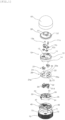
- FIG. 1 is an exploded perspective view showing a disassembled state of the self-destructing fuse structure according to the present invention
- FIG. 3 is a perspective view showing the state in which a second pin strikes a connection portion between a fixing member and a centrifugal force weight
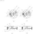
- FIGs. 4A and 4B are top plan views showing the state in which the centrifugal force weight separated from the fixing member through the operation shown in FIG. 3 is pushed outwards by the rotational force of the grenade to release interruption of an impact weight
- FIGs. 4C and 4D are cross-sectional views showing the state in which the centrifugal force weight separated from the fixing member through the operation shown in FIG.
- FIG. 5 is a view showing the operational state in which the centrifugal force weight pushed outwards in the operation shown in FIG. 4 short-circuits a first conductive wire, a protrusion that interrupts the impact weight releases the interruption of the impact weight, and, as a result, the released impact weight short-circuits a second conductive wire due to a speed change resulting from a grenade collision, FIG. 5A showing the state in which the first conductive wire is not short-circuited, FIG. 5B showing the state in which the centrifugal weight pushed outwards according to the operation shown in FIG.
- FIG. 6 is a top plan view showing an operational state of an opening and closing unit in which a protrusion formed under one of the two centrifugal force weights separated from the fixing member in the operation shown in FIG. 3 interrupts the rotation of a lower rotor and is pushed outwards by the rotational force of the grenade to release the interruption of the rotor, whereby, the self-destructing fuse structure according to the present invention becomes capable of rotation.
- the self-destructing fuse structure according to the present invention is largely formed of an upper plate structure 50, a lower plate structure 10, a substrate module 20, a first safety structure 30, and a second safety structure 40.
- the upper plate structure 50 is a configuration of an upper portion of the lower plate structure 10, that is, of a warhead side, and includes a first accommodation groove 51 and a second accommodation groove 52 disposed at a location away from the first accommodation groove 51.
- the first accommodation groove 51 and the second accommodation groove 52 include a first pin 11a and a second pin 12a accommodated therein to be described later, and serve to guide vertical movement of the first pin 11a and the second pin 12a.
- two of each of the first pin 11a and the second pin 12a may be provided, that is, they may be provided in pairs.
- each of the first accommodation groove 51 and the second accommodation groove 52 may be provided in a pair formed symmetrically with respect to a central portion.
- the lower plate structure 10 is configured to be coupled to a lower side of the upper plate structure 50, and a plurality of first coupling protrusions 53 are formed on a lower surface of the upper plate structure 50 along a circumferential direction thereof. Accordingly, the lower plate structure 10 includes a first coupling groove 13 coupled to the first coupling protrusion 53 along the circumferential direction on an upper surface thereof to perform stable coupling therebetween at an accurate position.
- the lower plate structure 10 includes a first guide hole 11 and a second guide hole 12 formed to correspond to respective positions of the first accommodation groove 51 and the second accommodation groove 52 in the upper plate structure 50 to which the lower plate structure 10 is coupled upwards, and, as such, the first pin 11a and the second pin 12a pass through the first guide hole 11 and the second guide hole 12, respectively, thereby achieving a structure movable upwards and downwards.
- first pin 11a is set to be placed over an upper end of the first guide hole 11, and the second pin 12a is set to be placed over an upper end of the second guide hole 12, respectively.
- a first tang spring 11b which is an inertia spring, is provided in the middle of the first guide hole 11, and the first pin 11a is placed on the first tang spring 11b.
- a second tang spring 12b which is an inertia spring, is provided in the middle of the second guide hole 12, and the second pin 12a is placed on the second tang spring 12b. In this manner described above, initial setting is performed.
- the first tang spring 11b and the second tang spring 12b are configured to prevent any movement of the first pin 11a and the second pin 12a, respectively, along the first guide hole 11 and the second guide hole 12 due to a weak impact or an external force, and to have a function of allowing the first pin 11a and the second pin 12a to move downwards along the first guide hole 11 and the second guide hole 12, respectively, when a grenade is fired and force exceeding an amount specified by setback is applied thereto.
- the substrate module 20 is a circuit board, which is represented as a PCB, coupled to a lower side of the lower plate structure 10.
- the lower plate structure 10 includes a plurality of second coupling protrusions 14 formed on a lower side surface thereof along the circumferential direction thereof, and the substrate module 20 includes a plurality of second coupling grooves 20a formed in an upper surface thereof and coupled to the plurality of second coupling protrusions 14.
- the substrate module 20 is formed of a first through-hole 22 corresponding to a position of the first pin 11a, the first through-hole 22 being provided to install a reserve battery 21 therein, a second through-hole 23 having a first conductive wire 23a formed thereacross, a third through-hole 24 including a second conductive wire 24a formed thereacross, and a fourth through-hole 26 having a size through which an end portion of the second pin 12a passes corresponding to a position of the second pin 12a.
- the reserve battery 21 is a battery for power supply.
- the reserve battery 21 is normally in an inactive state in which power is not supplied thereto, and is activated upon application of an impact thereto from the upper first pin 11a, thereby supplying power thereto.
- the reserve battery 21 is not positioned on the upper side of the substrate module 20 but is positioned in the first through-holes 22, whereby a sufficient stroke space between the reserve battery 21 and the first pin 11a may be secured, and the first pin 11a may accelerate while passing through the secured space, thereby more strongly striking the reserve battery 21.
- FIG. 2 is a cross-sectional view showing the state in which the first pin 11a strikes the reserve battery 21.
- the reserve battery 21 is a battery configured to be activated by an external strike applied thereto to generate electricity, and a bottom surface of an electrode protruding from side to side formed on an upper portion of the reserve battery 21 is electrically connected to the substrate module 20. Further, since the reserve battery 21 may be applied to various products as well as that of Patent Document KR 10-1445616 held by the present applicant, a detailed description of the reserve battery 21 will be omitted to prevent the gist of the present invention from being obscured.
- the first pin 11a and the second pin 12a are each symmetrically formed in pairs
- the first through-hole 22, the second through-hole 23, the third through-hole 24, and the fourth through-hole 26 provided in the substrate module 20 are also each symmetrically formed in pairs.
- An electric detonator 25 is installed at a lower side of the substrate module 20 to generate a detonation caused by an electrical signal received through a short circuit of the second conductive wire 24a.
- the first safety structure 30 is configured to be installed at the lower side of the substrate module 20.
- the second coupling protrusion 14 protruding downwards from the lower plate structure 10 is supported by the second coupling groove 20a formed in the substrate module 20, and protrudes further downwards from the second coupling groove 20a to be accommodated in and coupled into a third coupling groove 30a in the first safety structure 30.
- the first safety structure 30 includes a centrifugal force weight 31 disposed therein corresponding to the position of the second through-hole 23, and an impact weight 32 disposed therein corresponding to the position of the third through-hole 24.
- the first safety structure 30 has a first detonator hole 33 formed in the center thereof so that the electric detonator 25 penetrates the same and approaches a spit-back 73 provided at a lower side of the first safety structure 30.
- the first safety structure 30 has a centrifugal force weight accommodation groove 34 and an impact weight accommodation groove 35 for the accommodation of the centrifugal force weight 31 and the impact weight 32.
- the centrifugal force weight accommodation groove 34 has a size to allow the centrifugal force weight 31 to be moved in a predetermined range by the centrifugal force from the center to the outside.
- the first safety structure 30 further includes a reserve battery accommodation groove 36 in which a lower portion of the reserve battery 21 mounted in the first through-hole 22 formed in the circuit board 20 is accommodated.
- a fixing member 31a which is configured to temporarily fix the centrifugal force weight 31 in an initial stage to prevent movement thereof, is installed outside the centrifugal force weight 31. Further, a V-shaped groove is formed at a connection portion between the centrifugal force weight 31 and the fixing member 31a so that the connection portion therebetween may be relatively easily broken, and the fixing member 31a and the centrifugal force weight 31 may be separated from each other by the impact applied thereto by the second pin 12a moving through the fourth through-hole 26.
- the centrifugal force weight 31 includes a fixing protrusion 31b to fix the impact weight 32 installed adjacent thereto at an initial position so that the same does not protrude upwards, and a short-circuit protrusion 31c formed at an upper portion thereof, the short-circuit protrusion 31c passing through the second through-hole 23 and protruding from the same to cut the first conductive wire 23a.
- a protrusion 31d formed at a lower end of one of the two centrifugal force weights 31, the one centrifugal force weight 31 being installed so that a spring 38 is compressed by the centrifugal force, interrupts rotation of a rotor 43 of the second safety structure 40, and releases the interruption of the rotor 43 mounted on the second safety structure 40 when pushed toward the circumference by rotation of the grenade.
- the protrusion 31d also serves to prevent the rotor 43 from returning back to an initial position thereof due to a restoring force of the compressed spring 38.
- the second safety structure 40 is coupled to a lower side of the first safety structure 30, a plurality of third coupling protrusions 30b are formed on a lower side surface of the first safety structure 30 along a circumference thereof, and a plurality of fourth coupling grooves 40a coupled thereto are formed in an upper side of the second safety structure 40, thereby providing a structure for stable coupling at an accurate position.
- the spit-back 73 is positioned at a lower side of the second safety structure 40, and a second detonator hole 41 is formed in the second safety structure 40 so that the electric detonator 25 in the spit-back 73 is easily ignited.
- an opening and closing unit 42 is provided to close the second detonator hole 41 in an initial stage and to open the second detonator hole 41 for detonation when detonation conditions are satisfied.
- the plurality of fourth coupling protrusions 49 are formed on the lower side surface of the second safety structure 40 along the circumference thereof so as to rotate together with the rotation of the grenade, and the fifth coupling groove 71 coupled thereto allows the second safety structure 40 to be coupled to the base plate 70 of the fuse unit of the grenade.
- a spit-back accommodation groove 72 is formed in the base plate 70 positioned at the lower side of the second safety structure 40, the spit-back 73 is positioned in the spit-back accommodation groove 72, and the second detonator hole 41 is formed in the lower side of the second safety structure 40 so that the electric detonator 25 is close to the spit-back 73 to be reliably ignited.
- the opening and closing unit 42 is provided to close the second detonator hole 41 in the initial stage and to open the second detonator hole 41 for detonation when the detonation conditions are satisfied.
- the opening and closing unit 42 is configured to be opened by centrifugal force in consideration of the firing characteristics of the grenade.
- the rotor 43 having an area larger than that of the second detonator hole 41, is installed with respect to a rotation shaft 42a eccentric to a side surface of the second detonator hole 41 disposed in the center.
- a penetrating portion 43a capable of opening the second detonator hole 41 during the rotation of the rotor 43 is formed in the rotor 43, which is rotatable laterally around the rotation shaft 42a. That is, the rotor 43 blocks a space between the second detonator hole 41 and the electric detonator 25 in an initial stage, and rotates by eccentric centrifugal force around the rotation shaft 42a during the rotation of the grenade so that the penetrating portion 43a is aligned with a position of the second detonator hole 41. Accordingly, the spit-back 73 is positionally aligned with the electric detonator 25 and mechanically armed so that the flame can be transmitted.
- the rotor 43 is formed so that an opening-and-closing side portion thereof having a large area with respect to the rotation shaft 42a covers the second detonator hole 41. Further, an outer peripheral surface of the opening-and-closing side portion of the rotor 43 has a circular arc formed therearound with respect to the first rotation shaft 42a, and the outer peripheral surface having the circular arc forms a gear 43b to be engaged with a first gear unit 45a to be described later.
- a relatively heavy weight unit 43c is formed on a rotation side portion opposite the penetrating portion 43a with respect to the rotational shaft 42a, thereby facilitating rotation of the rotor 43 by the centrifugal force.
- the rotor 43 is a safety device configured to prevent the grenade from detonating within distance within which safety is required in an initial stage of grenade firing. Accordingly, the rotor 43 is initially fixed to block initial movement thereof, and is mechanically armed after the grenade moves a safe distance away.
- the selected centrifugal force weight 31 includes a support protrusion 31d, the support protrusion 31d being formed at a lower side of the selected centrifugal force weight 31 and protruding downwards to a lower side of the first safety structure 30 to contact the rotor 43 and prevent rotation thereof.
- a fifth through-hole 37 is formed in the first safety structure 30 so that the support protrusion 31d can move downwards in a state of penetrating the same.
- the support protrusion 31d maintains a fixed state so that the rotor 43 does not move when the centrifugal force weight 31 is in an initial position, and the centrifugal force weight 31 moves outwards by centrifugal force to be separated from the rotor 43 and to permit rotation of the rotor 43.
- the rotor 43 includes a protrusion formed therein, the protrusion being in contact with the centrifugal force weight 31 at the initial position, and the spring 38 configured to push the centrifugal force weight 31 to the center may be formed on the outside of the centrifugal force weight 31, which serves to support the rotor 43.
- a speed adjustment unit 46 is installed on a side surface of the rotor 43 to prevent the rotor 43 from being quickly opened and closed and to prevent the grenade from being armed within a distance requiring safety, the speed adjustment unit 46 appropriately slowing down the rotation speed of the rotor 43.
- the speed adjustment unit 46 preferably includes a speed reduction unit configured to contact a conversion gear unit 45 to reduce the rotation speed of the conversion gear unit 45, the conversion gear unit 45 being disposed above the gear 43b of the rotor 43 and rotating while being engaged with the gear 43b of the rotor 43 to reduce the rotation speed of the rotor 43, the rotor 43 including the gear 43b formed on the outer peripheral surface thereof with respect to a rotation shaft of the rotor 43 and the weight unit 43c being formed on the opposite side of the gear 43b.
- the spit-back 73 is positioned in the spit-back accommodation groove 72 in the base plate 70 located below the second safety structure 40, and the spit-back 73 is detonated by ignition of the upper electric detonator 25 when the second detonator hole 41 is open.
- FIG. 8 is a view showing the state in which an opening and closing unit according to another embodiment of the present invention is combined with the base plate 70.
- the penetrating portion 43a which may communicate with the second detonator hole 41 in a straight line when the rotor 43 is moved by centrifugal force, includes connection gunpowder 48 therein, the connecting gunpowder 48 being located between the electric detonator 25 and the spit-back 73. After that, the connection gunpowder 48 is detonated in a state of overlapping the electric detonator 25. Accordingly, a detonation pressure passes through the second detonator hole 41 and ignites the spit-back 73 installed below the second safety structure 40.
- the centrifugal force weight 31 overcomes the action force of an externally mounted spring due to centrifugal force and presses the spring to be pushed outwards along the centrifugal force weight accommodation groove 34.
- the short-circuit protrusion 31c formed on the centrifugal force weight 31 short-circuits the first conductive wire 23a, thereby releasing a safety and preparing for detonation of the electric detonator 25.
- the impact weight 32 short-circuits the second conductive wire 24a to detonate the electric detonator 25 when an impact is applied to the grenade.
- the circuit is electronically controlled so that the grenade becomes armed after moving a safe distance away.
- the support protrusion 31d formed below the centrifugal force weight 31 and configured to prevent rotation of the rotor 43, moves along the fifth through-hole 37.
- the support protrusion 31d is separated from the rotor 43, the fixed state of the rotor 43 is released and the opening-and-closing side portion of the rotor 43, having a large area, rotates outwards by receiving centrifugal force around the rotation shaft 42a.
- the gear 43b formed on the outer circumferential surface of the opening-and-closing side portion of the rotor 43 is engaged with the conversion gear unit 45 including the first gear unit 45a and the second gear unit 45b formed therein to reduce the rotation speed of the rotor 43, and the rotation speed of the rotor 43 is appropriately adjusted by the conversion gear unit 45 and the speed reduction unit, which is configured to reduce the rotation speed of the conversion gear unit 45 by contacting the same.
- the second detonator hole 41 is open so that the electric detonator 25 may detonate the spit-back 73 formed at the lower side of the second safety structure 40.
- the speed adjustment unit reduces the speed at which the rotor 43 opens, thereby preventing the situation in which the second detonator hole 41 opens and the spit-back 73 is detonated while the grenade remains within a distance within which safety is required.
- the impact weight 32 passes through the third through-hole 24 due to inertia and protrudes upwards to cut and short-circuit the second conductive wire 24a, which is mounted in the third through-hole 24.
- the spit-back 73 is ignited. After that, a booster in a grenade body catches fire, main gunpowder detonates, and the grenade detonates.
- the substrate module 20 in order to prepare for the situation in which the impact weight 32 fails to cut the second conductive wire 24a even when an impact is applied to the grenade, it is preferable for the substrate module 20 to include an additional electronic switch to cause the grenade to self-destruct after the lapse of a time set by a designer, thereby preventing subsequent death caused by the undetonated grenade.
- the electric detonator 25 may operate when the second conductive wire 24a is cut by the impact weight 32.
- damage to the lower plate structure 10 and the substrate module 20 and shape deformation thereof may be caused by the upper plate structure 50, and, as such, the impact weight 32 may not cut the second conductive wire 24a.
- FIG. 7 is a perspective view showing the configuration of a substrate module according to another embodiment of the present invention, and also showing the configuration in which the second conductive wire 24a is installed so as to extend outside the third through-hole 24 so as to immediately detect the above-mentioned damage to the substrate module 20.
- a second conductive wire 24a' is provided along the outer rim of the substrate module 20, the second conductive wire 24a' is cut when damage to a substrate occurs at various impact angles and the electric detonator 25 is operated, thereby preventing the grenade from remaining undetonated due to damage to the grenade.
Landscapes
- Engineering & Computer Science (AREA)
- General Engineering & Computer Science (AREA)
- Air Bags (AREA)
- Fuses (AREA)
- Percussive Tools And Related Accessories (AREA)
- Design And Manufacture Of Integrated Circuits (AREA)
- Switches Operated By Changes In Physical Conditions (AREA)
Claims (12)
- Elektronische selbstzerstörende Zünderstruktur, umfassend:eine untere Plattenstruktur (10), die ein erstes Führungsloch (11), das sie vertikal durchdringt, und einen ersten Stift (11a), der in das erste Führungsloch so eingesetzt ist, dass er sich vertikal bewegt, umfasst;ein Substratmodul (20), das an einer unteren Seite der unteren Plattenstruktur angeordnet ist, wobei das Substratmodul ein erstes Durchgangsloch (22), das entsprechend einer Position des ersten Stifts positioniert ist, wobei das erste Durchgangsloch eine Reservebatterie (21) aufweist, die darin so montiert ist, dass sie aktiviert wird, wenn sie von dem ersten Stift getroffen wird, ein zweites Durchgangsloch (23), das einen ersten leitfähigen Draht (23a) umfasst, der darüber hinweg ausgebildet und so konfiguriert ist, dass er einen Kurzschluss erfasst, ein drittes Durchgangsloch (24), das einen zweiten leitfähigen Draht (24a) umfasst, der darüber hinweg ausgebildet und so konfiguriert ist, dass er einen Kurzschluss erfasst, und einen elektrischen Detonator (25), der an einer unteren Seite davon montiert ist, wobei der elektrische Detonator in Reaktion auf den Kurzschluss des zweiten leitfähigen Drahts in Richtung einer unteren Seite ein elektrisches Detonationssignal ausgibt und entsprechend dem elektrischen Detonationssignal detoniert, umfasst; undeine erste Sicherheitsstruktur (30), die an einer unteren Seite des Substratmoduls angeordnet ist, wobei die erste Sicherheitsstruktur ein Zentrifugalkraftgewicht (31), das so konfiguriert ist, dass es durch Zentrifugalkraft von einem Zentrum nach außen bewegt wird und den ersten leitfähigen Draht kurzschließt, ein Aufprallgewicht (32), das so konfiguriert ist, dass es durch Trägheit aufsteigt und absteigt und den zweiten leitfähigen Draht kurzschließt, und ein erstes Detonatorloch (33), das so ausgebildet ist, dass es dem elektrischen Detonator ermöglicht, nahe an einem Rückstoß (73) zu sein, umfasst.
- Elektronische selbstzerstörende Zünderstruktur nach Anspruch 1, wobei die untere Plattenstruktur weiterhin ein zweites Führungsloch (12), das sie vertikal durchdringt, und einen zweiten Stift (12a), der in das zweite Führungsloch so eingesetzt ist, dass er sich vertikal bewegt, umfasst,das Substratmodul weiterhin ein viertes Durchgangsloch (26) umfasst, das so konfiguriert ist, dass der zweite Stift hindurchgeführt wird, unddie erste Sicherheitsstruktur weiterhin ein Fixierungselement umfasst, das so konfiguriert ist, dass es die Zentrifugalkraftgewicht vorübergehend fixiert und durch den Druck von dem zweiten Stift durch den Rückstoß, der bei dem Abfeuern einer Granate erzeugt wird, freigegeben wird.
- Elektronische selbstzerstörende Zünderstruktur nach Anspruch 1 oder 2, weiterhin umfassend eine zweite Sicherheitsstruktur (40), die an einer unteren Seite der ersten Sicherheitsstruktur angeordnet ist, wobei die zweite Sicherheitsstruktur ein zweites Detonatorloch (41), das so ausgebildet ist, dass es eine Sprengkraft des elektrischen Detonators auf den an einer unteren Seite davon angeordneten Rückstoß überträgt, und eine Öffnungs- und Schließeinheit (42), die so konfiguriert ist, dass sie das zweite Detonatorloch in einer Ausgangsstufe schließt und das zweite Detonatorloch durch Zentrifugalkraft öffnet, umfasst.
- Elektronische selbstzerstörende Zünderstruktur nach Anspruch 3, wobei die Öffnungs- und Schließeinheit einen Rotor (43) umfasst, der so konfiguriert ist, dass er einen Raum zwischen dem zweiten Detonatorloch und dem elektrischen Detonator blockiert, wobei der Rotor einen Durchdringungsabschnitt (43a) umfasst, der so konfiguriert ist, dass er das zweite Detonatorloch öffnet, wenn der Rotor in einer Umfangsrichtung einer Granate durch Zentrifugalkraft um eine Drehwelle (42a) bewegt wird, die auf einer Seitenfläche des zweiten Detonatorlochs ausgebildet ist,die erste Sicherheitsstruktur ferner einen Stützvorsprung (31d), der so konfiguriert ist, dass er in Richtung einer unteren Seite des Zentrifugalkraftgewichts vorsteht, und ein fünftes Durchgangsloch (37), das so konfiguriert ist, dass es dem Stützvorsprung ermöglicht, sich in einem Zustand des Durchdringens der ersten Sicherheitsstruktur nach unten zu bewegen, umfasst, undder Stützvorsprung den Rotor fixiert, um dessen Bewegung zu verhindern, und durch Zentrifugalkraft nach außen bewegt wird, um eine Drehung des Rotors zu ermöglichen.
- Elektronische selbstzerstörende Zünderstruktur gemäß Anspruch 4, wobei der Rotor ein Zahnrad (43b), das entlang einer äußeren Umfangsfläche eines Öffnungs- und Schließseitenabschnitts davon in Bezug auf die Drehwelle ausgebildet ist, wobei der Öffnungs- und Schließseitenabschnitt das Öffnen und Schließen des zweiten Detonatorlochs steuert, und eine Gewichtseinheit (43c), die an einem Rotationsseitenabschnitt ausgebildet ist, der in einer entgegengesetzten Richtung des Öffnungs- und Schließseitenabschnitts davon angeordnet ist, umfasst, weiterhin umfassend:eine Umwandlungszahnradeinheit (45), die eine erste Zahnradeinheit (45a), die an einem oberen Abschnitt davon angeordnet und so konfiguriert ist, dass sie rotiert, während sie mit dem Zahnrad des Rotors in Eingriff steht, und eine zweite Zahnradeinheit (45b), die an einem unteren Abschnitt davon angeordnet ist und ein relativ großes Übersetzungsverhältnis aufweist, undeine Geschwindigkeitseinstelleinheit (46), die so konfiguriert ist, dass sie die Umwandlungszahnradeinheit kontaktiert, um eine Drehzahl der Umwandlungszahnradeinheit durch Rotationswiderstand zu reduzieren.
- Elektronische selbstzerstörende Zünderstruktur nach Anspruch 4 oder 5, wobei das Verbindungsschießpulver (48) auf dem Durchdringungsabschnitt angeordnet ist, der in dem Rotor ausgebildet ist, um die Zündung des Rückstoßes zu beschleunigen.
- Elektronische selbstzerstörende Zünderstruktur nach einem der Ansprüche 2 bis 6, soweit abhängig von Anspruch 2, ferner umfassend eine kappenförmige obere Plattenstruktur (50), die so konfiguriert ist, dass sie die untere Plattenstruktur von oben abdeckt, um damit gekoppelt zu werden, wobei die obere Plattenstruktur eine erste Aufnahmenut (51) und eine zweite Aufnahmenut (52) umfasst, die so konfiguriert sind, dass sie die oberen Enden des ersten Stifts bzw. des zweiten Stifts aufnehmen.
- Elektronische selbstzerstörende Zünderstruktur nach einem der Ansprüche 1 bis 7, wobei das Substratmodul einen zweiten leitfähigen Draht (24a') umfasst, der so vorgesehen ist, dass er sich entlang eines äußeren Randes davon erstreckt, und so konfiguriert ist, dass er die gleiche Wirkung wie ein Kurzschluss des zweiten leitfähigen Drahts aufweist, wenn das Substratmodul beschädigt wird.
- Elektronische selbstzerstörende Zünderstruktur nach einem der Ansprüche 1 bis 8, wobei der erste leitfähige Draht und der zweite leitfähige Draht eine hohe Leitfähigkeit aufweisen, jedoch dünne leitfähige Drähte sind, wobei der erste leitfähige Draht und der zweite leitfähige Draht durch Drahtbonden oder Wedge-Bonden gebildet sind.
- Elektronische selbstzerstörende Zünderstruktur nach einem der Ansprüche 1 bis 9, wobei der erste Stift und der zweite Stift auf den jeweiligen Zapfenfedern (11b, 12b) angeordnet und darauf montiert sind.
- Elektronische selbstzerstörende Zünderstruktur nach einem der Ansprüche 1 bis 10, wobei die Reservebatterie eine Elektrode umfasst, die an einem oberen Abschnitt davon ausgebildet und so konfiguriert ist, dass sie von Seite zu Seite vorsteht, wobei die Elektrode eine Bodenfläche aufweist, die elektrisch mit dem Substratmodul verbunden ist.
- Elektronische selbstzerstörende Zünderstruktur nach einem der Ansprüche 1 bis 11, wobei das Zentrifugalkraftgewicht umfasst:ein Fixierelement (31a), das so konfiguriert ist, dass es eine Bewegung des Zentrifugalkraftgewichts in einer festen Position verhindert,einen Kurzschlussvorsprung (31c), der so konfiguriert ist, dass er den ersten leitfähigen Draht durchtrennt,einen Fixiervorsprung (31b), der so konfiguriert ist, dass er das Aufschlaggewicht unterbricht, undeinen Stützvorsprung (31d), der so konfiguriert ist, dass er die Rotation eines Rotors unterbricht.
Applications Claiming Priority (2)
| Application Number | Priority Date | Filing Date | Title |
|---|---|---|---|
| KR20190131287 | 2019-10-22 | ||
| PCT/KR2020/014064 WO2021080242A1 (ko) | 2019-10-22 | 2020-10-15 | 전자식 자폭 신관 구조체 |
Publications (4)
| Publication Number | Publication Date |
|---|---|
| EP4040099A1 EP4040099A1 (de) | 2022-08-10 |
| EP4040099A4 EP4040099A4 (de) | 2023-11-08 |
| EP4040099B1 true EP4040099B1 (de) | 2024-10-02 |
| EP4040099C0 EP4040099C0 (de) | 2024-10-02 |
Family
ID=75619452
Family Applications (1)
| Application Number | Title | Priority Date | Filing Date |
|---|---|---|---|
| EP20879307.5A Active EP4040099B1 (de) | 2019-10-22 | 2020-10-15 | Elektronische selbstzerstörende zünderstruktur |
Country Status (8)
| Country | Link |
|---|---|
| US (1) | US12111144B2 (de) |
| EP (1) | EP4040099B1 (de) |
| JP (1) | JP7597391B2 (de) |
| KR (1) | KR102310186B1 (de) |
| IL (1) | IL292374B2 (de) |
| SA (1) | SA522432307B1 (de) |
| WO (1) | WO2021080242A1 (de) |
| ZA (1) | ZA202205087B (de) |
Families Citing this family (3)
| Publication number | Priority date | Publication date | Assignee | Title |
|---|---|---|---|---|
| JP7597391B2 (ja) | 2019-10-22 | 2024-12-10 | セジュ エンジニアリング カンパニー,リミテッド | 電子式自爆信管構造体 |
| CN116002019A (zh) * | 2022-12-07 | 2023-04-25 | 杭州航海仪器有限公司 | 一种水下对接潜标的全自动进水自毁装置 |
| CN116399189B (zh) * | 2023-02-06 | 2025-05-02 | 北京理工大学 | 一种实现小口径炮弹引信可靠发火的mems开关及其控制方法 |
Family Cites Families (21)
| Publication number | Priority date | Publication date | Assignee | Title |
|---|---|---|---|---|
| JPS5436800B2 (de) * | 1973-12-19 | 1979-11-10 | ||
| US4178855A (en) * | 1978-03-20 | 1979-12-18 | The United States Of America As Represented By The Secretary Of The Navy | Explosive actuated arming switch device |
| ES2068738B1 (es) | 1992-12-30 | 1998-05-01 | Instalaza Sa | Espoleta electronica autodestructiva. |
| KR950004734A (ko) * | 1993-07-28 | 1995-02-18 | 이대원 | 스위칭 회로 |
| US6142080A (en) * | 1998-01-14 | 2000-11-07 | General Dynamics Armament Systems, Inc. | Spin-decay self-destruct fuze |
| JP2001116500A (ja) * | 1999-10-20 | 2001-04-27 | Fujitsu General Ltd | 電気信管 |
| US7895947B1 (en) * | 2007-07-03 | 2011-03-01 | The United States Of America As Represented By The Secretary Of The Navy | Weapon fuse method |
| US7971532B1 (en) * | 2008-12-15 | 2011-07-05 | The United States Of America As Represented By The Secretary Of The Navy | Microelectromechanical systems ignition safety device |
| KR101078153B1 (ko) | 2009-02-20 | 2011-10-28 | 주식회사 풍산 | 유탄의 자폭장치 |
| KR101016834B1 (ko) | 2009-02-24 | 2011-02-22 | 주식회사 풍산 | 자탄용 전자식 지연 자폭신관 |
| KR100915706B1 (ko) | 2009-06-12 | 2009-09-04 | 한국씨앤오테크 주식회사 | 유탄발사기용 40㎜ 연습탄 |
| US8061272B2 (en) | 2009-08-17 | 2011-11-22 | Dse, Inc. | Mechanical command to arm fuze |
| US8468946B2 (en) * | 2010-01-19 | 2013-06-25 | Chemring Ordnance, Inc. | Low shrapnel door breaching projectile system |
| KR101174636B1 (ko) | 2010-05-20 | 2012-08-21 | 국방과학연구소 | 신관의 기폭 지연 장치 및 그 방법 |
| KR101317713B1 (ko) | 2011-07-06 | 2013-11-11 | 세주엔지니어링주식회사 | 1,2차 전지 및 비축전지 활성화를 위한 타격장치를 구비하여 전자식 자폭기능을 부여한 신관 |
| KR101445616B1 (ko) | 2012-11-22 | 2014-10-06 | 세주엔지니어링주식회사 | 비축전지 |
| KR101695357B1 (ko) | 2014-12-16 | 2017-01-11 | 국방과학연구소 | 신관의 안전장전장치 및 이를 구비한 포탄 |
| IL250231B (en) * | 2017-01-22 | 2021-02-28 | Rafael Advanced Defense Systems Ltd | A system for quick stepping of a blasting or excitation assembly |
| KR101782492B1 (ko) * | 2017-04-04 | 2017-09-27 | 국방과학연구소 | 회전탄 신관 |
| KR102032555B1 (ko) * | 2018-02-28 | 2019-10-15 | 주식회사 한화 | 로터형 안전 장전 장치 및 이를 구비하는 신관 조립체 |
| JP7597391B2 (ja) | 2019-10-22 | 2024-12-10 | セジュ エンジニアリング カンパニー,リミテッド | 電子式自爆信管構造体 |
-
2020
- 2020-10-15 JP JP2022524123A patent/JP7597391B2/ja active Active
- 2020-10-15 US US17/770,002 patent/US12111144B2/en active Active
- 2020-10-15 EP EP20879307.5A patent/EP4040099B1/de active Active
- 2020-10-15 IL IL292374A patent/IL292374B2/en unknown
- 2020-10-15 WO PCT/KR2020/014064 patent/WO2021080242A1/ko not_active Ceased
- 2020-10-19 KR KR1020200135130A patent/KR102310186B1/ko active Active
-
2022
- 2022-04-19 SA SA522432307A patent/SA522432307B1/ar unknown
- 2022-05-09 ZA ZA2022/05087A patent/ZA202205087B/en unknown
Also Published As
| Publication number | Publication date |
|---|---|
| IL292374B2 (en) | 2025-02-01 |
| JP7597391B2 (ja) | 2024-12-10 |
| KR20210067876A (ko) | 2021-06-08 |
| IL292374B1 (en) | 2024-10-01 |
| IL292374A (en) | 2022-06-01 |
| WO2021080242A1 (ko) | 2021-04-29 |
| EP4040099A4 (de) | 2023-11-08 |
| ZA202205087B (en) | 2023-10-25 |
| US12111144B2 (en) | 2024-10-08 |
| US20220390217A1 (en) | 2022-12-08 |
| JP2022553739A (ja) | 2022-12-26 |
| EP4040099C0 (de) | 2024-10-02 |
| SA522432307B1 (ar) | 2022-12-21 |
| BR112022007479A2 (pt) | 2022-07-12 |
| EP4040099A1 (de) | 2022-08-10 |
| KR102310186B1 (ko) | 2021-10-08 |
Similar Documents
| Publication | Publication Date | Title |
|---|---|---|
| EP4040099B1 (de) | Elektronische selbstzerstörende zünderstruktur | |
| US6622629B2 (en) | Submunition fuzing and self-destruct using MEMS arm fire and safe and arm devices | |
| US7748324B2 (en) | Method to ensure payload activation of ordnance | |
| US5485788A (en) | Combination explosive primer and electro-explosive device | |
| TW200409903A (en) | Dual mode fuze | |
| USH251H (en) | Increased safety in use, and improved function, of ammunition items | |
| CA2161221C (en) | Self-destruct fuse for improved conventional munitions | |
| CN115823971B (zh) | 一种巡飞弹机电触发引信 | |
| US6244184B1 (en) | Fuze for submunition grenade | |
| US5147975A (en) | Remotely settable, multi-output, electronic time fuze and method of operation | |
| US6145439A (en) | RC time delay self-destruct fuze | |
| US2789508A (en) | Safety and arming mechanism | |
| KR102576940B1 (ko) | 전원 공급부, 자탄 및 이를 구비한 발사체 | |
| JP6919837B2 (ja) | 水中爆弾用安全装置 | |
| KR101016834B1 (ko) | 자탄용 전자식 지연 자폭신관 | |
| BR112022007479B1 (pt) | Estrutura de fusível eletrónico autodestrutível | |
| US6050195A (en) | Self neutralizing fuze | |
| KR100416004B1 (ko) | 자탄용 전자식지연 자폭신관 장치 | |
| EP0605356A1 (de) | Elektronischer Selbstzerlegungszünder | |
| US2993442A (en) | Trip and shear mechanism | |
| US12163771B2 (en) | Arming and disarming munition with redundant safety feature to return munition to a safe, unarmed state | |
| US3636879A (en) | Airburst and inertia impact fuze assembly for munitions | |
| RU2268457C1 (ru) | Контактное взрывательное устройство | |
| JP2001116500A (ja) | 電気信管 | |
| WO2023129119A2 (en) | A grenade detonator and usage method thereof |
Legal Events
| Date | Code | Title | Description |
|---|---|---|---|
| STAA | Information on the status of an ep patent application or granted ep patent |
Free format text: STATUS: THE INTERNATIONAL PUBLICATION HAS BEEN MADE |
|
| PUAI | Public reference made under article 153(3) epc to a published international application that has entered the european phase |
Free format text: ORIGINAL CODE: 0009012 |
|
| STAA | Information on the status of an ep patent application or granted ep patent |
Free format text: STATUS: REQUEST FOR EXAMINATION WAS MADE |
|
| 17P | Request for examination filed |
Effective date: 20220505 |
|
| AK | Designated contracting states |
Kind code of ref document: A1 Designated state(s): AL AT BE BG CH CY CZ DE DK EE ES FI FR GB GR HR HU IE IS IT LI LT LU LV MC MK MT NL NO PL PT RO RS SE SI SK SM TR |
|
| DAV | Request for validation of the european patent (deleted) | ||
| DAX | Request for extension of the european patent (deleted) | ||
| REG | Reference to a national code |
Ref country code: DE Ref legal event code: R079 Free format text: PREVIOUS MAIN CLASS: F42C0009160000 Ipc: F42C0019060000 Ref country code: DE Ref legal event code: R079 Ref document number: 602020038849 Country of ref document: DE Free format text: PREVIOUS MAIN CLASS: F42C0009160000 Ipc: F42C0019060000 |
|
| A4 | Supplementary search report drawn up and despatched |
Effective date: 20231010 |
|
| RIC1 | Information provided on ipc code assigned before grant |
Ipc: F42C 9/14 20060101ALI20231004BHEP Ipc: F42C 9/16 20060101ALI20231004BHEP Ipc: F42C 1/10 20060101ALI20231004BHEP Ipc: F42C 15/34 20060101ALI20231004BHEP Ipc: F42C 15/00 20060101ALI20231004BHEP Ipc: F42C 15/40 20060101ALI20231004BHEP Ipc: F42C 15/24 20060101ALI20231004BHEP Ipc: F42C 15/26 20060101ALI20231004BHEP Ipc: F42C 19/06 20060101AFI20231004BHEP |
|
| GRAP | Despatch of communication of intention to grant a patent |
Free format text: ORIGINAL CODE: EPIDOSNIGR1 |
|
| STAA | Information on the status of an ep patent application or granted ep patent |
Free format text: STATUS: GRANT OF PATENT IS INTENDED |
|
| INTG | Intention to grant announced |
Effective date: 20240424 |
|
| GRAS | Grant fee paid |
Free format text: ORIGINAL CODE: EPIDOSNIGR3 |
|
| GRAA | (expected) grant |
Free format text: ORIGINAL CODE: 0009210 |
|
| STAA | Information on the status of an ep patent application or granted ep patent |
Free format text: STATUS: THE PATENT HAS BEEN GRANTED |
|
| AK | Designated contracting states |
Kind code of ref document: B1 Designated state(s): AL AT BE BG CH CY CZ DE DK EE ES FI FR GB GR HR HU IE IS IT LI LT LU LV MC MK MT NL NO PL PT RO RS SE SI SK SM TR |
|
| REG | Reference to a national code |
Ref country code: GB Ref legal event code: FG4D |
|
| REG | Reference to a national code |
Ref country code: CH Ref legal event code: EP |
|
| REG | Reference to a national code |
Ref country code: IE Ref legal event code: FG4D |
|
| REG | Reference to a national code |
Ref country code: DE Ref legal event code: R096 Ref document number: 602020038849 Country of ref document: DE |
|
| U01 | Request for unitary effect filed |
Effective date: 20241023 |
|
| U07 | Unitary effect registered |
Designated state(s): AT BE BG DE DK EE FI FR IT LT LU LV MT NL PT RO SE SI Effective date: 20241106 |
|
| U20 | Renewal fee for the european patent with unitary effect paid |
Year of fee payment: 5 Effective date: 20241115 |
|
| PG25 | Lapsed in a contracting state [announced via postgrant information from national office to epo] |
Ref country code: IS Free format text: LAPSE BECAUSE OF FAILURE TO SUBMIT A TRANSLATION OF THE DESCRIPTION OR TO PAY THE FEE WITHIN THE PRESCRIBED TIME-LIMIT Effective date: 20250202 Ref country code: HR Free format text: LAPSE BECAUSE OF FAILURE TO SUBMIT A TRANSLATION OF THE DESCRIPTION OR TO PAY THE FEE WITHIN THE PRESCRIBED TIME-LIMIT Effective date: 20241002 |
|
| PG25 | Lapsed in a contracting state [announced via postgrant information from national office to epo] |
Ref country code: ES Free format text: LAPSE BECAUSE OF FAILURE TO SUBMIT A TRANSLATION OF THE DESCRIPTION OR TO PAY THE FEE WITHIN THE PRESCRIBED TIME-LIMIT Effective date: 20241002 |
|
| PG25 | Lapsed in a contracting state [announced via postgrant information from national office to epo] |
Ref country code: NO Free format text: LAPSE BECAUSE OF FAILURE TO SUBMIT A TRANSLATION OF THE DESCRIPTION OR TO PAY THE FEE WITHIN THE PRESCRIBED TIME-LIMIT Effective date: 20250102 |
|
| PG25 | Lapsed in a contracting state [announced via postgrant information from national office to epo] |
Ref country code: GR Free format text: LAPSE BECAUSE OF FAILURE TO SUBMIT A TRANSLATION OF THE DESCRIPTION OR TO PAY THE FEE WITHIN THE PRESCRIBED TIME-LIMIT Effective date: 20250103 |
|
| PG25 | Lapsed in a contracting state [announced via postgrant information from national office to epo] |
Ref country code: CZ Free format text: LAPSE BECAUSE OF FAILURE TO SUBMIT A TRANSLATION OF THE DESCRIPTION OR TO PAY THE FEE WITHIN THE PRESCRIBED TIME-LIMIT Effective date: 20241002 Ref country code: PL Free format text: LAPSE BECAUSE OF FAILURE TO SUBMIT A TRANSLATION OF THE DESCRIPTION OR TO PAY THE FEE WITHIN THE PRESCRIBED TIME-LIMIT Effective date: 20241002 |
|
| PG25 | Lapsed in a contracting state [announced via postgrant information from national office to epo] |
Ref country code: RS Free format text: LAPSE BECAUSE OF FAILURE TO SUBMIT A TRANSLATION OF THE DESCRIPTION OR TO PAY THE FEE WITHIN THE PRESCRIBED TIME-LIMIT Effective date: 20250102 |
|
| REG | Reference to a national code |
Ref country code: CH Ref legal event code: PL |
|
| PG25 | Lapsed in a contracting state [announced via postgrant information from national office to epo] |
Ref country code: SM Free format text: LAPSE BECAUSE OF FAILURE TO SUBMIT A TRANSLATION OF THE DESCRIPTION OR TO PAY THE FEE WITHIN THE PRESCRIBED TIME-LIMIT Effective date: 20241002 |
|
| PG25 | Lapsed in a contracting state [announced via postgrant information from national office to epo] |
Ref country code: MC Free format text: LAPSE BECAUSE OF FAILURE TO SUBMIT A TRANSLATION OF THE DESCRIPTION OR TO PAY THE FEE WITHIN THE PRESCRIBED TIME-LIMIT Effective date: 20241002 |
|
| PG25 | Lapsed in a contracting state [announced via postgrant information from national office to epo] |
Ref country code: CH Free format text: LAPSE BECAUSE OF NON-PAYMENT OF DUE FEES Effective date: 20241031 |
|
| PG25 | Lapsed in a contracting state [announced via postgrant information from national office to epo] |
Ref country code: SK Free format text: LAPSE BECAUSE OF FAILURE TO SUBMIT A TRANSLATION OF THE DESCRIPTION OR TO PAY THE FEE WITHIN THE PRESCRIBED TIME-LIMIT Effective date: 20241002 |
|
| PLBE | No opposition filed within time limit |
Free format text: ORIGINAL CODE: 0009261 |
|
| STAA | Information on the status of an ep patent application or granted ep patent |
Free format text: STATUS: NO OPPOSITION FILED WITHIN TIME LIMIT |
|
| 26N | No opposition filed |
Effective date: 20250703 |
|
| PG25 | Lapsed in a contracting state [announced via postgrant information from national office to epo] |
Ref country code: IE Free format text: LAPSE BECAUSE OF NON-PAYMENT OF DUE FEES Effective date: 20241015 |
|
| U20 | Renewal fee for the european patent with unitary effect paid |
Year of fee payment: 6 Effective date: 20251031 |
|
| PGFP | Annual fee paid to national office [announced via postgrant information from national office to epo] |
Ref country code: GB Payment date: 20251030 Year of fee payment: 6 |
|
| PGFP | Annual fee paid to national office [announced via postgrant information from national office to epo] |
Ref country code: TR Payment date: 20251015 Year of fee payment: 6 |
|
| PG25 | Lapsed in a contracting state [announced via postgrant information from national office to epo] |
Ref country code: CY Free format text: LAPSE BECAUSE OF FAILURE TO SUBMIT A TRANSLATION OF THE DESCRIPTION OR TO PAY THE FEE WITHIN THE PRESCRIBED TIME-LIMIT; INVALID AB INITIO Effective date: 20201015 |
|
| PG25 | Lapsed in a contracting state [announced via postgrant information from national office to epo] |
Ref country code: HU Free format text: LAPSE BECAUSE OF FAILURE TO SUBMIT A TRANSLATION OF THE DESCRIPTION OR TO PAY THE FEE WITHIN THE PRESCRIBED TIME-LIMIT; INVALID AB INITIO Effective date: 20201015 |