EP4039622A1 - Fördervorrichtung und analysesystem - Google Patents
Fördervorrichtung und analysesystem Download PDFInfo
- Publication number
- EP4039622A1 EP4039622A1 EP20870462.7A EP20870462A EP4039622A1 EP 4039622 A1 EP4039622 A1 EP 4039622A1 EP 20870462 A EP20870462 A EP 20870462A EP 4039622 A1 EP4039622 A1 EP 4039622A1
- Authority
- EP
- European Patent Office
- Prior art keywords
- magnetic pole
- conveyance
- container
- conveyance container
- coil
- Prior art date
- Legal status (The legal status is an assumption and is not a legal conclusion. Google has not performed a legal analysis and makes no representation as to the accuracy of the status listed.)
- Pending
Links
Images






Classifications
-
- B—PERFORMING OPERATIONS; TRANSPORTING
- B65—CONVEYING; PACKING; STORING; HANDLING THIN OR FILAMENTARY MATERIAL
- B65G—TRANSPORT OR STORAGE DEVICES, e.g. CONVEYORS FOR LOADING OR TIPPING, SHOP CONVEYOR SYSTEMS OR PNEUMATIC TUBE CONVEYORS
- B65G54/00—Non-mechanical conveyors not otherwise provided for
- B65G54/02—Non-mechanical conveyors not otherwise provided for electrostatic, electric, or magnetic
-
- G—PHYSICS
- G01—MEASURING; TESTING
- G01N—INVESTIGATING OR ANALYSING MATERIALS BY DETERMINING THEIR CHEMICAL OR PHYSICAL PROPERTIES
- G01N35/00—Automatic analysis not limited to methods or materials provided for in any single one of groups G01N1/00 - G01N33/00; Handling materials therefor
- G01N35/02—Automatic analysis not limited to methods or materials provided for in any single one of groups G01N1/00 - G01N33/00; Handling materials therefor using a plurality of sample containers moved by a conveyor system past one or more treatment or analysis stations
- G01N35/04—Details of the conveyor system
-
- H—ELECTRICITY
- H02—GENERATION; CONVERSION OR DISTRIBUTION OF ELECTRIC POWER
- H02P—CONTROL OR REGULATION OF ELECTRIC MOTORS, ELECTRIC GENERATORS OR DYNAMO-ELECTRIC CONVERTERS; CONTROLLING TRANSFORMERS, REACTORS OR CHOKE COILS
- H02P25/00—Arrangements or methods for the control of AC motors characterised by the kind of AC motor or by structural details
- H02P25/02—Arrangements or methods for the control of AC motors characterised by the kind of AC motor or by structural details characterised by the kind of motor
- H02P25/06—Linear motors
- H02P25/064—Linear motors of the synchronous type
-
- B—PERFORMING OPERATIONS; TRANSPORTING
- B65—CONVEYING; PACKING; STORING; HANDLING THIN OR FILAMENTARY MATERIAL
- B65G—TRANSPORT OR STORAGE DEVICES, e.g. CONVEYORS FOR LOADING OR TIPPING, SHOP CONVEYOR SYSTEMS OR PNEUMATIC TUBE CONVEYORS
- B65G2203/00—Indexing code relating to control or detection of the articles or the load carriers during conveying
- B65G2203/02—Control or detection
- B65G2203/0208—Control or detection relating to the transported articles
- B65G2203/0233—Position of the article
-
- B—PERFORMING OPERATIONS; TRANSPORTING
- B65—CONVEYING; PACKING; STORING; HANDLING THIN OR FILAMENTARY MATERIAL
- B65G—TRANSPORT OR STORAGE DEVICES, e.g. CONVEYORS FOR LOADING OR TIPPING, SHOP CONVEYOR SYSTEMS OR PNEUMATIC TUBE CONVEYORS
- B65G2203/00—Indexing code relating to control or detection of the articles or the load carriers during conveying
- B65G2203/02—Control or detection
- B65G2203/0266—Control or detection relating to the load carrier(s)
-
- G—PHYSICS
- G01—MEASURING; TESTING
- G01N—INVESTIGATING OR ANALYSING MATERIALS BY DETERMINING THEIR CHEMICAL OR PHYSICAL PROPERTIES
- G01N35/00—Automatic analysis not limited to methods or materials provided for in any single one of groups G01N1/00 - G01N33/00; Handling materials therefor
- G01N35/02—Automatic analysis not limited to methods or materials provided for in any single one of groups G01N1/00 - G01N33/00; Handling materials therefor using a plurality of sample containers moved by a conveyor system past one or more treatment or analysis stations
- G01N35/04—Details of the conveyor system
- G01N2035/0474—Details of actuating means for conveyors or pipettes
- G01N2035/0477—Magnetic
-
- H—ELECTRICITY
- H02—GENERATION; CONVERSION OR DISTRIBUTION OF ELECTRIC POWER
- H02P—CONTROL OR REGULATION OF ELECTRIC MOTORS, ELECTRIC GENERATORS OR DYNAMO-ELECTRIC CONVERTERS; CONTROLLING TRANSFORMERS, REACTORS OR CHOKE COILS
- H02P25/00—Arrangements or methods for the control of AC motors characterised by the kind of AC motor or by structural details
- H02P25/02—Arrangements or methods for the control of AC motors characterised by the kind of AC motor or by structural details characterised by the kind of motor
- H02P25/06—Linear motors
Definitions
- the inspection of the specified analysis item is performed on the specimen (sample) such as blood, plasma, serum, urine, and other body fluids.
- This specimen analysis system connects devices having a plurality of functions and automatically executes the processing of each process.
- an analysis unit that executes a plurality of analyses such as biochemistry and immunity
- a pretreatment unit that executes a plurality of pretreatments required for this analysis, and the like are connected by a conveyor line and used as one sample analysis system.
- JP-B-6072052 states that "the system can further include a container carrier detection device adapted to detect the presence and position of a container carrier located on the conveyance plane.
- the container carrier detection device provides the optimized tracking of container carriers placed on the conveyance surface” (see paragraph [0034]).
- a corresponding electromagnetic actuator is provided under the target destination thereof. If a particular field or region does not need to be accessible, the electromagnetic actuator at that position may be omitted” (See paragraph [0053]).
- the electromagnetic actuator means a magnetic pole (a set of a magnetic body core and a coil).
- the specimen analysis system requires a plurality of container carrier detection devices for detecting the position of the magnetically active devices provided on the specimen conveyance carrier. Further, since these container carrier detection devices need to be arranged on the transfer surface side, a dedicated printed circuit board is required. Therefore, there is a problem that the device becomes complicated and the cost increases.
- the present disclosure provides a technique for sensitively detecting the position of each actuator (magnetic pole) without using a container carrier detection device.
- the present disclosure provides a conveying device that conveys a conveyance container including a magnet or a magnetic body to a target position along a conveyance path
- the conveying device includes a conveyance surface configured by arranging a plurality of magnetic poles including a core and a coil and having a conveyance path, a drive unit for supplying a current to the coil, and a position detection unit for performing a process of estimating the position of the conveyance container, in which the position detection unit performs a process of exciting a first magnetic pole selected to detect the position of the conveyance container, and applying a voltage to at least one second magnetic pole that is a peripheral magnetic pole within a predetermined range from the first magnetic pole and is different from the first magnetic pole in a direction in which the polarity becomes opposite to the exciting current of the first magnetic pole, and a process of estimating the position of the conveyance container based on a current value of the first magnetic pole.
- the present embodiment relates to a conveying device used for a specimen analysis system such as a specimen analysis device for analyzing a biological sample (hereinafter referred to as "specimen"), for example, blood, plasma, serum, urine, or other body fluid, and a specimen pretreatment device for executing a pretreatment necessary for this analysis.
- a specimen analysis device for analyzing a biological sample
- serum for example, blood, plasma, serum, urine, or other body fluid
- specimen pretreatment device for executing a pretreatment necessary for this analysis.
- the embodiments of the present disclosure may be implemented by software running on a general-purpose computer or may be implemented by dedicated hardware or a combination of software and hardware.
- Fig. 1 is a diagram showing a schematic configuration of a conveying device 1 according to the present embodiment.
- Fig. 1 schematically shows an outline of a conveying device in which two adjacent magnetic poles 25 and a permanent magnet 10 operate relatively.
- the conveying device 1 includes a conveyance plane (see Fig. 5 and the like) that conveys the conveyance container 20 (synonymous with the conveyance container (specimen holder) 20: see Fig. 2 ) provided with the permanent magnet (magnetic body) 10 thereon, a magnetic pole 25 that is arranged below the conveyance plane and includes a core 22 which is a magnetic body and a coil 21 which is a winding wound around the outer peripheral side of the core 22, a drive unit (drive device for driving the conveyance container) 50 for applying a voltage to the coil 21 of the magnetic pole 25, a current detection unit 30 for detecting the current flowing through the coil 21, and a calculation unit (control device for controlling the drive device) 40 for controlling the drive unit 50 based on the detected current value.
- a conveyance plane see Fig. 5 and the like
- the permanent magnet 10 is arranged in the conveyance container 20.
- a permanent magnet 10 such as neodymium or ferrite is used.
- other magnets or soft magnetic bodies may be used instead of the permanent magnet 10.
- the permanent magnet 10 and the soft magnetic body may be used in combination.
- the "magnetic body” means a permanent magnet 10, another magnet or a soft magnetic body, or a combination of a permanent magnet 10 and a soft magnetic body.
- the basic principle will be described using a permanent magnet 10 as an example (representative example) of a magnetic body.
- Fig. 2 is a schematic view showing a partial sectional configuration example of the conveying device 1 shown in Fig. 1 .
- the conveyance container 20 such as a specimen holder is configured such that the holding portion of the specimen (container) and the permanent magnet 10 are integrated.
- the conveyance container 20 is arranged so as to face the magnetic pole 25 via the conveyance plane.
- an electromagnetic force is generated in the core 22 by flowing a current through the coil 21 of the magnetic pole 25, and the permanent magnet 10 arranged in the conveyance container 20 is controlled to slide above the space between the plurality of magnetic poles 25 (between a magnetic pole 25 and a magnetic pole 25) and on the conveyance plane so as to relatively move, whereby the conveyance container 20 is conveyed to a desired position.
- relative position information between the permanent magnet 10 and the magnetic pole 25 is required. This is to efficiently apply the electromagnetic force generated in the core 22 to the permanent magnet 10 by flowing a current through the coil 21 of the magnetic pole 25, and to move the permanent magnet 10 in a target direction. For example, it is assumed that the permanent magnet 10 is located above (immediately above) one of the two magnetic poles 25. Even if a voltage is applied to the magnetic pole 25a (coil 21a) directly below the permanent magnet 10, no force (thrust) is generated in the permanent magnet 10 in the conveyance direction.
- the position detection of the conveyance container 20 on the conveyance path will be described.
- the magnetic field generated by the permanent magnet 10 acts on the magnetic pole 25.
- the magnitude of the magnetic field is difference between the magnetic field acting on the magnetic pole 25 on the side closer to the permanent magnet 10 and that acting on the magnetic pole 25 on the far side. That is, the magnitude of the magnetic field acting on the magnetic pole 25 changes depending on the relative position between the permanent magnet 10 and the magnetic pole 25.
- the core 22 is composed of a magnetic body and has the property that the magnetic flux passing through the core 22 becomes difficult to pass as the magnetic flux increases.
- a magnetic flux (magnetic field) generated by the current is generated in the core 22. Therefore, a magnetic flux (magnetic field) generated by the permanent magnet 10 and a magnetic flux (magnetic field) generated by the current flowing through the coil (winding) 21 are generated in the core 22.
- a current flows through a coil (winding) 21
- a magnetic field is generated around the coil (winding) 21, and the generated magnetic flux is proportional to the current value passed through. This proportionality constant is called inductance.
- the inductance changes due to the saturation characteristic of the core 22.
- the inductance changes depending on the magnitude of the magnetic flux generated in the core 22. That is, the inductance of the coil (winding) 21 changes depending on the magnitude of the magnetic flux of the permanent magnet 10. This means that the inductance of the coil (winding) 21 changes depending on the position of the permanent magnet 10. That is, when there is a magnetic field from the permanent magnet 10, magnetic saturation occurs in the coil (winding) 21 and the magnetic permeability decreases, and thus, the current flowing through the coil (winding) 21 changes.
- the inductance L can be calculated by detecting the current flowing through the coil (winding) 21 and how the current flows. That is, if the inductance L of the coil (winding) 21 that changes depending on the position of the permanent magnet 10 is detected, the position of the permanent magnet 10 that affects the inductance can be obtained. Therefore, the drive unit 50 is connected to the coil (winding) 21 of the magnetic poles 25, and a current detecting unit 30 (for example, a resistor is arranged) for detecting the current value flowing through the coil (winding) 21 is provided. Then, a voltage is applied to the coil (winding) 21 by the drive unit 50, the current value generated by the voltage is detected by the current detection unit 30, and the value is read by the calculation unit 40.
- a current detecting unit 30 for example, a resistor is arranged
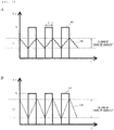
- Fig. 3 is a diagram for illustrating a voltage waveform applied to the coil by the conveying device 1 to detect the position of the conveyance container 20 and a current waveform corresponding to the voltage waveform according to the basic principle.
- the magnitude (V) and pulse width (T) of the voltage pulse 60 are determined by how much voltage is applied to the magnetic pole 25. Then, when the permanent magnet 10 of the conveyance container 20 approaches the magnetic pole 25, the current waveform 70a changes to the current waveform 70b due to the magnetic saturation of the magnetic pole 25.
- the conveying device 1 includes the current detection unit 30 that detects a current and can detect the position of the conveyance container 20 based on the current value that is detected by the current detection unit 30 and measured by the calculation unit 40. That is, the position of the conveyance container 20 is detected by detecting the amount of change in the current detected by the current detection unit 30 (the amount of change in the rising/falling current of the position detection pulse).
- the current detection unit 30 detects a current and can detect the position of the conveyance container 20 based on the current value that is detected by the current detection unit 30 and measured by the calculation unit 40. That is, the position of the conveyance container 20 is detected by detecting the amount of change in the current detected by the current detection unit 30 (the amount of change in the rising/falling current of the position detection pulse).
- Fig. 3A when the magnetic pole 25 is not affected by the permanent magnet 10 of the conveyance container 20, a current change amount is I1.
- the current change amount is 12, which is larger than I1.
- the current detection unit 30 may be a series resistor, for example, one using a current transformer, one using a Hall current sensor, or the like, but is not limited thereto.
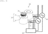
- Fig. 4 is a schematic diagram showing a specific configuration example for current detection.
- the magnetic pole 25 is composed of a columnar core 22 and a coil (winding) 21 wound around the outer peripheral side of the core.
- the permanent magnet 10 is arranged so as to face the columnar core 22.
- the drive unit 50 is connected to the coil (winding) 21.
- a resistor 31 for detecting the current flowing through the coil (winding) 21 is provided between the coil (winding) 21 and the drive unit 50.
- magnetic poles are arranged in a plurality of rows and a plurality of columns to form a conveyance path.
- Fig. 5 is a top view showing a schematic configuration example of a conveyance plane on which the magnetic poles 25 of the conveying device 1 are arranged.
- the magnetic poles 25 having 5 rows and 5 columns are aligned in a grid pattern to form a conveyance path.
- the conveyance path is set to travel on the magnetic poles 25 arranged in a grid pattern.
- the conveying device 1 can convey the conveyance container 20 provided with the permanent magnet 10 in any target direction (conveyance direction) by exciting the magnetic pole 25 (applying a voltage to the magnetic pole 25 (coil 21)) based on the target conveyance path.
- the conveyance containers on the magnetic poles adjacent to the top, bottom, left, and right of the magnetic pole are attracted, and thus, the conveyance path is desirable to have a grid pattern of one row and one column (if the magnetic poles 25 are spread closely, the placed plurality of conveyance containers 20 are likely to collide with each other) . Therefore, the magnetic pole 25 can be omitted in the region outside the conveyance path, and the component cost can be reduced or the weight can be reduced.
- the maximum distance between the conveyance container 20 and the magnetic pole 25 on the conveyance plane is d (maximum distance when the conveyance container is out of the conveyance path) .
- the maximum distance between the conveyance container 20 and the magnetic pole 25 is d / 2.
- Japanese Patent No. 6072052 (PTL 1), for example, it may be considered that a dedicated device for detecting the position of the conveyance container 20 is arranged at a position on the conveyance plane where the magnetic pole 25 is not arranged, but a control circuit for the dedicated device is required, which leads to an increase in cost.
- the conveying device 1 first selects one from the nearest magnetic poles 25 in order to detect the presence or absence of the conveyance container 20 at a position on the conveyance plane where the magnetic pole 25 is not arranged.
- the nearest magnetic pole 25 for example, based on the conveyance history information of the conveyance container 20 on the conveyance path (path passed up to the present time, movement speed (may be an average value), moving time up to the present time), it is possible to select from a plurality of magnetic poles 25 around the conveyance position scheduled at the present time.
- Fig. 5 shows a candidate example of the nearest magnetic pole 25.
- the number of the nearest magnetic poles is 3 or 2 as an exception.
- the conveyance container 20 is not on the magnetic poles 25 on both sides of the selected nearest magnetic pole 25 based on the above-mentioned position detection method (method for checking the current change amount: based on the table showing the relationship between the current change amount and the position (for example, see Fig. 6 ), the relative position corresponding to the detected current change amount can be obtained) .
- the conveyance container 20 is located on the magnetic poles 25 on both sides thereof, the conveyance container 20 can be moved to another place on the conveyance path by the above-mentioned driving method.
- a predetermined pulse voltage is applied to the selected magnetic pole 25, and the presence or absence of the conveyance container 20 at a position separated from the selected magnetic pole 25 by a distance of x can be detected from the current change amount, as in the above-mentioned position detection method of the conveyance container 20.
- Fig. 6 is a graph in which the distance from the selected magnetic pole 25 (nearest magnetic pole 25) is on the horizontal axis and the current change amount is on the vertical axis. This makes it possible to know the distance from the selected magnetic pole 25 corresponding to the current change amount.
- the conveyance container 20 is detected at a position separated from the magnetic pole 25 by a distance of d / 2 or more, and thus, the presence or absence of the conveyance container 20 at a place deviating from the conveyance path may be determined by the threshold value different from that during conveyance or the threshold value based on the current change amount at a position separated from the magnetic pole by a distance of d / 2 or more.
- the conveyance container 20 exists at a position of a distance of d / 2 or more, it is confirmed that the conveyance container 20 is not on the magnetic poles 25 on both sides of the selected magnetic pole 25, and thus, it can be known that the conveyance container (specimen holder) 20 exists at both or at least one side of the position where the magnetic poles 25 on both sides of the selected magnetic pole 25 are not arranged.
- the specimen conveying device 1 performs position detection (position estimation) of the conveyance container 20 using the coil current (or the current flowing through the shunt resistor), and the presence or absence of the conveyance container (specimen holder) 20 can be detected without using a dedicated position detection device even if the conveyance container 20 deviates to a position outside the conveyance path on the conveyance surface where the magnetic poles 25 are not arranged, or is stuck for some reason.
- the conveying device 1 according to the improved plan will be described with reference to Figs. 7 to 12 .
- the improved plan is improved in the position detection method of the magnetic pole 25 described in the basic principle and the detection sensitivity can be improved by utilizing all or at least one of the peripheral coils 211 in order to detect the presence or absence of the conveyance container (specimen holder) 20 at a position separated from the coil 21 by a distance of d / 2 or more.
- the present disclosure proposes an improved plan in which the basic principle is improved so that the position of the conveyance container 20 can be detected more sensitively.
- the peripheral coil 211 means a plurality of coils 211 (coils other than the nearest coil) whose distance from the selected coil 21 (nearest coil 21: the nearest coil can be selected according to the method described in the basic principle) is d, d ⁇ 2, or 2d, and the number thereof is 2 (in the case of the conveyance plane configuration example shown in Fig. 7 ), 6 (in the case of the conveyance plane configuration example shown in Fig. 8 ), and 10 (in the case of the conveyance plane configuration example shown in Fig. 9 ) and the like, respectively.
- a voltage (any voltage value) is applied to the peripheral coil 211 in a direction in which the polarity becomes opposite to the exciting current of the selected coil (nearest coil) 21.
- This voltage may be direct current or pulse voltage.
- the coil current does not have to be direct current but the average value can be substantially constant.
- Fig. 10 is a diagram showing an example of a voltage characteristic having a characteristic opposite to the exciting current of the selected coil 21. When a voltage having a characteristic opposite to the exciting current is used as a pulse voltage, any duty ratio can be adapted according to the current value to be passed.
- the conveying device 1 can move the conveyance container (specimen holder) 20 to another place by a normal driving method.
- the coil 211 around the selected coil (nearest coil) 21 is excited with the polarity opposite to the exciting current to the selected coil 21, and a predetermined pulse voltage is applied to the selected coil 21 as in the above-mentioned basic principle. Then, the presence or absence of the conveyance container (specimen holder) 20 at a position separated from the coil 21 by a distance of d is detected based on the current change amount, as in the normal position detection method of the conveyance container (specimen holder) 20.
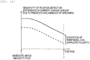
- Fig. 11 is an explanatory diagram showing a relationship between the distance between the magnetic pole and the conveyance container and the current change amount of the coil when a pulse voltage is applied. As can be seen from Fig. 11 , when a predetermined pulse voltage is applied to the selected coil 21 in a state of being excited with the polarity opposite to the exciting current, the position detection sensitivity of the conveyance container 20 is improved.
- Fig. 12 is a diagram schematically showing a magnetic path when the magnetic pole 25 is excited in the conveying device 1 according to the improved plan.
- the magnetic pole 25 is composed of a coil 21 and a core (iron core) 22.
- the current change amount used to detect the position of the conveyance container (specimen holder) 20 is inversely proportional to the inductance of the coil 21. Further, the inductance of the coil 21 is roughly proportional to the relative magnetic permeability of the core (iron core) 22. Since the magnetic field generated from the magnet 10 (or magnetic body) passes through the core (iron core) 22, the magnetic field in the core (iron core) 22 changes (Fig.
- the current change amount changes depending on the presence or absence of the conveyance container (specimen holder) 20 near the coil 21.
- the core (iron core) 22 changes to a state in which magnetic saturation is likely to occur, and the change in the current change amount depending on the presence or absence of the conveyance container (specimen holder) 20 becomes large (Fig.12C) .
- the specimen conveying device that detects the position of the conveyance container using the coil current (or the current flowing through the shunt resistor), even if the conveyance container 20 deviates to a position outside the conveyance path on the conveyance surface where the magnetic poles are not arranged, or is stuck for some reason, it is possible to detect the presence or absence of the conveyance container (specimen holder) 20 without using a dedicated container carrier detection device (position detection device) as in the basic principle. Although the number of coils to be excited increases as compared with the case of the basic principle, the detection sensitivity can be improved.
- the analysis system performs a process of detecting the conveyance container 20 at each place on the conveyance surface of each conveying device 1 described in the above-mentioned basic principle or improved plan, when it is presumed that the conveyance container 20 has deviated to a position outside the conveyance path on the conveyance surface where the magnetic poles are not arranged, or is stuck for some reason.
- Fig. 13 is a diagram showing a schematic configuration example of the analysis system 100 according to the present embodiment.
- the analysis system 100 includes a control computer 101, a plurality of analysis devices 102, and a plurality of conveying devices 1 for conveying conveyance containers (specimen holders) 20 between the analysis devices 102.
- the number of analysis devices 102 and the number of conveying devices 1 vary depending on the type of specimen to be analyzed and the details of analysis.
- the control computer 101 controls the entire system, such as designating a conveyance path for conveying the conveyance container (specimen holder) 10 and the order of analysis. Further, the control computer 101 performs a designated operation in response to an instruction input from the operator.
- Fig. 14 is a block diagram showing a control circuit configuration example of each conveying device 1 that configures a conveyance path of the analysis system 100.
- the control circuit of the conveying device 1 includes a processor 201 composed of a CPU, an MPU, or the like, a memory 202 for storing various data and operating parameters, a position detection unit 203 for calculating the position detection of the conveyance container 20, a coil drive unit 205 that drives the coil 21 by applying a voltage to a coil terminal 204, an input device 206 composed of input and output ports for serial communication and parallel communication, a keyboard, a mouse, a touch panel, and the like, and an output device 207 composed of a display, a printer, and the like, which are connected to each other by a bus 208.
- the function of the position detection unit 203 is included in the calculation unit 40, and the coil drive unit 205 corresponds to the drive unit 50 described above. It should be noted that some functions of the position detection unit 203 may be implemented by a software program and the processor 201 may execute the functions.
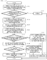
- Fig. 15 is a flowchart for illustrating the details of the position detection processing performed by the analysis system 100.
- the position detection unit 203 and the processor 201 execute each process as the operation main body.
- the function of the position detection unit 203 is implemented by the software program, only the processor 201 will be necessary to be described as the operation main body.
- the position detection unit 203 checks the presence or absence of the conveyance container 20 on the conveyance path on which the magnetic pole 25 is laid by the method described in the above-mentioned basic principle. That is, the position detection unit 203 detects the current change amount when a voltage is applied to the coil 21 of each magnetic pole 25 configuring the path, applies the current change amount to the table ( Fig. 6 ), and determines whether or not the conveyance container 20 exists on the path.
- the position detection unit 203 determines whether the conveyance container 20 deviates from the magnetic pole 25 of the conveyance path. For example, when the target conveyance container 20 is not detected near the coil position specified by the control command or near the expected position on the conveyance path calculated based on the elapsed time (the approximate position is calculated based on the conveyance speed and the elapsed time), it can be determined that the conveyance container 20 has deviated from the conveyance path. If it is determined that the deviation has been made (Yes in step 1502), the process proceeds to step 1502. If it is determined that the deviation has not occurred (No in step 1502), the process proceeds to step 1503.
- the position detection unit 203 determines that the conveyance operation of the conveyance container 20 is normally performed, and ends the position detection processing.
- the position detection unit 203 notifies the processor 201 that the conveyance container 20 has deviated from the magnetic pole 25 of the conveyance path. Then, the processor 201 that has received the notification notifies the control computer (external server) 101.
- the position detection unit 203 determines whether another conveyance container 20 exists around the target conveyance container 20 determined to have deviated, and if another conveyance container 20 exists, retracts another conveyance container 20.
- the presence or absence of another conveyance container 20 can be determined by the same method as the above basic principle.
- the processor 201 receives the position information of the conveyance container 20 on the adjacent conveyance path from the processor 201 of the adjacent conveying device 1.
- the coil drive unit 205 is controlled so as to move the other conveyance container 20 to the adjacent conveying device 1 and secures a space in which the target conveyance container 20 can move on the conveyance path.
- the position detection unit 203 checks the presence or absence of the conveyance container 20 at the position where the magnetic pole 25 is not arranged by the method described in the above-mentioned improved plan (according to the improved plan, the presence or absence of the conveyance container 20 can be detected even if the conveyance container 20 deviates to a place where the magnetic pole 25 (coil 21) is not arranged) .
- the position detection unit 203 checks whether the target conveyance container 20 is at a position where the magnetic pole 25 is not arranged. When it is determined that the target conveyance container 20 is at a position where the magnetic pole 25 is not arranged (Yes in step 1507), the process proceeds to step 1508. When it is determined that the target conveyance container 20 is at a position where the magnetic pole 25 is arranged (No in step 1507), the process proceeds to step 1511.
- the position detection unit 203 Since the position detection unit 203 is to prevent the two conveyance containers 20 from being drawn into the same place at the same time before exciting the adjacent coil to draw in the conveyance container, it is necessary to first check that there is no other conveyance container 20 on the magnetic pole 25 adjacent to the selected magnetic pole 25 (the nearest coil 21 of the target conveyance container 20).
- the processor 201 receives a notification (that the target conveyance container 20 is at a position where the magnetic pole 25 is not arranged, and the other conveyance container 20 is not on the adjacent magnetic pole 25) from the position detection unit 203, the coil 21 of the magnetic pole 25 adjacent to the target conveyance container 20 is excited, and the coil drive unit 205 is controlled so as to draw the target conveyance container 20 onto the conveyance path.
- the processor 201 determines whether or not the draw-in is successful. If the draw-in is successful (Yes in step 1508), the process proceeds to step 1510. If the draw-in fails (No in step 1509), the process proceeds to step 1512.
- the processor 201 notifies the control computer (external server) 101 of the analysis system 100 that the conveyance container 20 has been successfully drawn into the conveyance path. Then, upon receiving this notification, the control computer 101 restarts or continues the operation of the analysis system 100.
- the position detection unit 203 notifies the processor 201 that the target conveyance container 20 cannot be observed on the conveyance surface (the place where the magnetic pole 25 is arranged and the place where the magnetic pole 25 is not arranged).
- the processor 201 Upon receiving the notification, notifies the control computer (external server) 101 that the target conveyance container 20 cannot be observed.
- control computer external server
- cannot be observed on the conveyance surface can be defined as, for example, meaning that the target conveyance container 20cannot be observed in a predetermined region or at and around the place where the target conveyance container 20 is originally supposed to exist.
- the position detection unit 203 notifies the processor 201 that the target conveyance container 20 has deviated from the conveyance path and cannot be moved. Upon receiving this notification, the processor 201 notifies the control computer (external server) 101 that the target conveyance container 20 cannot be moved on the conveyance path. This allows the system operator to accurately check the place where the abnormality has occurred.
- the control computer 101 determines that an abnormality has occurred, and interrupts the operation of the analysis system 100.
- the control computer 101 may restart or continue the conveyance processing of the remaining conveyance containers (specimen holders) 20 while avoiding the place where the abnormality has occurred.
- the conveyance processing can be continued or restarted.
- the analysis system 100 configured to connect a plurality of conveying devices 1 capable of detecting the position of the conveyance container 20 using the coil current (or the current flowing through the shunt resistor), even if a certain conveyance container 20 deviates to a position on the conveyance surface outside the conveyance path where the magnetic poles are not arranged or is stuck for some reason, it becomes possible to detect the presence or absence of the target conveyance container (specimen holder) 20 without using a dedicated container carrier detection device (position detection device), and to draw it onto the conveyance path or display a message to the system administrator, thereby making it possible to continue or restart the conveyance processing.
- a dedicated container carrier detection device position detection device
- the magnetic pole (first magnetic pole) selected for detecting the position of the conveyance container 20 is excited, a voltage is applied to at least one second magnetic pole that is the peripheral magnetic pole (see Figs. 7 to 9 ) within a predetermined range from the first magnetic pole and is different from the first magnetic pole, in a direction in which the polarity becomes opposite to the exciting current of the first magnetic pole, and the position of the conveyance container is detected (estimated) based on the current value of the first magnetic pole.
- the voltage applied to the peripheral magnetic pole can be a DC voltage or a pulse voltage in the direction in which the polarity becomes opposite.
- magnetic poles are arranged in a number smaller than the number that can be arranged.
- the conveyance surface can be configured to arrange a plurality of magnetic poles 25 in a grid pattern.
- the analysis system (may be referred to as a conveyance system) 100 according to the present embodiment includes a plurality of analysis devices 102, a plurality of conveying devices 1 arranged between the plurality of analysis devices, and a control computer 101 for controlling the operation of the analysis devices 102 and the conveying devices 1.
- a control operation of the system including position detection processing is executed according to the flowchart of Fig. 15 .
- the first magnetic pole selected for detecting the position of the conveyance container 20 is excited, and a voltage is applied to at least one second magnetic pole that is the peripheral magnetic pole within a predetermined range from the first magnetic pole and is different from the first magnetic pole, in a direction in which the polarity becomes opposite to the exciting current of the first magnetic pole.
- the control computer 101 determines the processing stop, processing restart, and processing continuation in the analysis system 100 based on the determination result.
- the present disclosure is not limited to the above-described embodiments and includes various modifications.
- the above-described embodiment is specifically described in order to explain the present disclosure in an easy-to-understand manner and is not necessarily limited to the one having all the described configurations.
- the present disclosure can also be embodied by a program code of software that implements the functions of the embodiment.
- a storage medium in which the program code is recorded is provided to the system or device, and the computer (or CPU or MPU) of the system or device reads out the program code stored in the storage medium.
- the program code itself read from the storage medium implements the function of the above-described embodiment, and the program code itself and the storage medium storing the program code itself configure the present disclosure.
- Examples of the storage medium for supplying such a program code include a flexible disk, a CD-ROM, a DVD-ROM, a hard disk, an optical disk, a magneto-optical disk, a CD-R, a magnetic tape, a non-volatile memory card, a ROM, and the like.
- the OS operating system
- the CPU of the computer or the like performs a part or all of the actual processing based on the instruction of the program code, and the functions of the above-described embodiment may be implemented by the processing.
- the program code may be stored in a storage means such as a hard disk or a memory of the system or device, or a storage medium such as a CD-RW or a CD-R, and the computer (or CPU or MPU) of the system or device may read and execute the program code stored in the storage means or the storage medium at the time of use.
- a storage means such as a hard disk or a memory of the system or device, or a storage medium such as a CD-RW or a CD-R
- the computer (or CPU or MPU) of the system or device may read and execute the program code stored in the storage means or the storage medium at the time of use.
- control lines and information lines show what is considered necessary for explanation, and do not necessarily show all the control lines and information lines in the product. All configurations may be interconnected.
Landscapes
- Physics & Mathematics (AREA)
- Health & Medical Sciences (AREA)
- Life Sciences & Earth Sciences (AREA)
- Chemical & Material Sciences (AREA)
- Analytical Chemistry (AREA)
- Biochemistry (AREA)
- General Health & Medical Sciences (AREA)
- General Physics & Mathematics (AREA)
- Immunology (AREA)
- Pathology (AREA)
- Engineering & Computer Science (AREA)
- Power Engineering (AREA)
- Control Of Linear Motors (AREA)
- Automatic Analysis And Handling Materials Therefor (AREA)
- Non-Mechanical Conveyors (AREA)
- Control Of Conveyors (AREA)
Applications Claiming Priority (2)
| Application Number | Priority Date | Filing Date | Title |
|---|---|---|---|
| JP2019181674A JP7323410B2 (ja) | 2019-10-01 | 2019-10-01 | 搬送装置、および分析システム |
| PCT/JP2020/033809 WO2021065362A1 (ja) | 2019-10-01 | 2020-09-07 | 搬送装置、および分析システム |
Publications (2)
| Publication Number | Publication Date |
|---|---|
| EP4039622A1 true EP4039622A1 (de) | 2022-08-10 |
| EP4039622A4 EP4039622A4 (de) | 2023-10-18 |
Family
ID=75271443
Family Applications (1)
| Application Number | Title | Priority Date | Filing Date |
|---|---|---|---|
| EP20870462.7A Pending EP4039622A4 (de) | 2019-10-01 | 2020-09-07 | Fördervorrichtung und analysesystem |
Country Status (5)
| Country | Link |
|---|---|
| US (1) | US12325599B2 (de) |
| EP (1) | EP4039622A4 (de) |
| JP (2) | JP7323410B2 (de) |
| CN (1) | CN114450596B (de) |
| WO (1) | WO2021065362A1 (de) |
Cited By (1)
| Publication number | Priority date | Publication date | Assignee | Title |
|---|---|---|---|---|
| EP4279428A4 (de) * | 2021-01-15 | 2025-01-01 | Hitachi High-Tech Corporation | Probentransportsystem und probentransportverfahren |
Families Citing this family (9)
| Publication number | Priority date | Publication date | Assignee | Title |
|---|---|---|---|---|
| EP4339141A4 (de) * | 2021-05-13 | 2025-05-28 | Hitachi High-Tech Corporation | Probenfördervorrichtung, probenanalysesystem und probenförderverfahren |
| JP7701214B2 (ja) * | 2021-08-26 | 2025-07-01 | 株式会社日立ハイテク | 搬送装置、搬送装置を備えた検体分析システム、および、搬送装置を備えた検体前処理装置 |
| WO2023081834A1 (en) * | 2021-11-05 | 2023-05-11 | Siemens Healthcare Diagnostics Inc. | Electromagnetic pcb topologies for automation track systems |
| CN118489207A (zh) * | 2022-01-26 | 2024-08-13 | 株式会社日立高新技术 | 输送装置以及输送方法 |
| JP7735528B2 (ja) * | 2022-02-25 | 2025-09-08 | 株式会社日立ハイテク | 搬送装置、および搬送方法 |
| JP7825512B2 (ja) * | 2022-05-25 | 2026-03-06 | 株式会社日立ハイテク | 搬送装置 |
| WO2024100885A1 (ja) * | 2022-11-11 | 2024-05-16 | 三菱電機株式会社 | 搬送システム |
| JP2025161469A (ja) * | 2024-04-12 | 2025-10-24 | 株式会社日立ハイテク | 検体処理システム |
| WO2026049037A1 (ja) * | 2024-08-31 | 2026-03-05 | 株式会社アスタリスク | 搬送システム |
Family Cites Families (29)
| Publication number | Priority date | Publication date | Assignee | Title |
|---|---|---|---|---|
| JPH0435602U (de) * | 1990-07-20 | 1992-03-25 | ||
| JPH05153704A (ja) * | 1991-11-26 | 1993-06-18 | Hitachi Ltd | 平面内磁気反発/吸引浮上搬送制御方法とその装置 |
| EP0871034B1 (de) | 1997-04-10 | 2007-03-07 | Hitachi, Ltd. | Automatische Analysevorrichtung |
| JP5031518B2 (ja) * | 1997-04-10 | 2012-09-19 | 株式会社日立製作所 | 自動分析装置 |
| ATE304458T1 (de) * | 1997-05-02 | 2005-09-15 | Automation Tooling Syst | Modulares fördersystem mit mehreren beweglichen elementen mit unabhängiger steuerung |
| JPH1159901A (ja) * | 1997-08-11 | 1999-03-02 | Murata Mach Ltd | キャリヤー移動装置 |
| JP3971741B2 (ja) * | 2003-11-18 | 2007-09-05 | ファナック株式会社 | 磁極位置検出装置 |
| EP1992410A1 (de) * | 2007-03-12 | 2008-11-19 | Stichting Dutch Polymer Institute | Mikrofluidisches System auf der Basis von Aktuatorelementen |
| DE102007014876B4 (de) * | 2007-03-26 | 2010-04-08 | Kba-Metronic Aktiengesellschaft | Transportsystem |
| JP5076839B2 (ja) * | 2007-11-28 | 2012-11-21 | トヨタ自動車株式会社 | 電磁アクチュエータ制御装置及び方法 |
| JP2009238966A (ja) * | 2008-03-26 | 2009-10-15 | Kiyotaka Ueda | 電力変換装置及びこれを利用した直流送電システム並びに電力貯蔵システム |
| EP2589968A1 (de) * | 2011-11-04 | 2013-05-08 | Roche Diagnostics GmbH | Laborprobenverteilungssystem, Laborsystem und Betriebsverfahren |
| EP2589967A1 (de) * | 2011-11-04 | 2013-05-08 | Roche Diagnostics GmbH | Laborprobenverteilungssystem und entsprechendes Betriebsverfahren |
| EP2589966A1 (de) * | 2011-11-04 | 2013-05-08 | Roche Diagnostics GmbH | Laborprobenverteilungssystem und entsprechendes Betriebsverfahren |
| CN104054258B (zh) * | 2012-01-27 | 2016-09-28 | 三菱电机株式会社 | 电动机驱动电路及永久磁铁同步电动机 |
| JP6359858B2 (ja) * | 2014-04-04 | 2018-07-18 | キヤノン電子株式会社 | 磁界検出装置および磁気識別装置 |
| EP2977765A1 (de) * | 2014-07-23 | 2016-01-27 | Roche Diagniostics GmbH | Probenbehälterträger, Laborprobenverteilungssystem und Laborautomatisierungssystem |
| EP2977766A1 (de) | 2014-07-24 | 2016-01-27 | Roche Diagniostics GmbH | Laborprobenverteilungssystem und Laborautomatisierungssystem |
| EP2995960B1 (de) * | 2014-09-09 | 2020-07-15 | Roche Diagniostics GmbH | Laborprobenverteilungssystem und Verfahren zur Kalibrierung von magnetischen Sensoren |
| EP2995958A1 (de) | 2014-09-15 | 2016-03-16 | Roche Diagniostics GmbH | Verfahren zum Betrieb einer Laborprobe Verteilungssystem, Laborprobenverteilungssystems und Laborautomatisierungssystem |
| EP3006943B1 (de) * | 2014-10-07 | 2020-04-22 | Roche Diagniostics GmbH | Modul für ein Laborprobenverteilungssystem, Laborprobenverteilungssystem und Laborautomatisierungssystem |
| JP6304560B2 (ja) * | 2015-03-12 | 2018-04-04 | 株式会社安川電機 | リニアモータ、リニアモータの制御システム |
| EP3153867B1 (de) * | 2015-10-06 | 2018-11-14 | Roche Diagniostics GmbH | Verfahren zur konfiguration eines laborautomatisierungssystems, laborprobenverteilungssystem und laborautomatisierungssystem |
| EP3153866A1 (de) * | 2015-10-06 | 2017-04-12 | Roche Diagnostics GmbH | Verfahren zur bestimmung einer übergabeposition und laborautomatisierungssystem |
| EP3260867A1 (de) * | 2016-06-21 | 2017-12-27 | Roche Diagnostics GmbH | Verfahren zur bestimmung einer übergabeposition und laborautomatisierungssystem |
| EP3343232B1 (de) * | 2016-12-29 | 2021-09-15 | Roche Diagnostics GmbH | Laborprobenverteilungssystem und laborautomatisierungssystem |
| WO2019021577A1 (ja) | 2017-07-26 | 2019-01-31 | パナソニックIpマネジメント株式会社 | 平面モータ |
| EP4279428B1 (de) * | 2021-01-15 | 2026-03-25 | Hitachi High-Tech Corporation | Probentransportsystem und probentransportverfahren |
| CN116364617A (zh) * | 2021-12-28 | 2023-06-30 | 细美事有限公司 | 物品输送系统和操作物品输送系统的方法 |
-
2019
- 2019-10-01 JP JP2019181674A patent/JP7323410B2/ja active Active
-
2020
- 2020-09-07 WO PCT/JP2020/033809 patent/WO2021065362A1/ja not_active Ceased
- 2020-09-07 US US17/761,845 patent/US12325599B2/en active Active
- 2020-09-07 CN CN202080066943.8A patent/CN114450596B/zh active Active
- 2020-09-07 EP EP20870462.7A patent/EP4039622A4/de active Pending
-
2023
- 2023-07-27 JP JP2023122672A patent/JP7478891B2/ja active Active
Cited By (2)
| Publication number | Priority date | Publication date | Assignee | Title |
|---|---|---|---|---|
| EP4279428A4 (de) * | 2021-01-15 | 2025-01-01 | Hitachi High-Tech Corporation | Probentransportsystem und probentransportverfahren |
| US12565389B2 (en) | 2021-01-15 | 2026-03-03 | Hitachi High-Tech Corporation | Sample conveyance system and sample conveyance method |
Also Published As
| Publication number | Publication date |
|---|---|
| EP4039622A4 (de) | 2023-10-18 |
| WO2021065362A1 (ja) | 2021-04-08 |
| US20220274792A1 (en) | 2022-09-01 |
| JP2021058052A (ja) | 2021-04-08 |
| CN114450596B (zh) | 2026-02-06 |
| US12325599B2 (en) | 2025-06-10 |
| JP7323410B2 (ja) | 2023-08-08 |
| JP7478891B2 (ja) | 2024-05-07 |
| CN114450596A (zh) | 2022-05-06 |
| JP2023129675A (ja) | 2023-09-14 |
Similar Documents
| Publication | Publication Date | Title |
|---|---|---|
| US12325599B2 (en) | Conveying device and analysis system | |
| JP6602901B2 (ja) | ラボラトリ試料分配システム及びラボラトリ自動化システム | |
| JP7304219B2 (ja) | 搬送装置 | |
| CN113474990A (zh) | 输送装置及具备该输送装置的检体分析系统、检体预处理装置及被输送体输送方法 | |
| US20210398723A1 (en) | Conveyance Apparatus, Sample Analysis System Including the Same, and Sample Preprocessing Apparatus | |
| JP2021058052A5 (de) | ||
| US20230211964A1 (en) | Transport Device and Analysis System | |
| EP4088831A1 (de) | Probentransportvorrichtung, probenanalysesystem, probenvorbehandlungssystem und probentransportverfahren | |
| US20230184798A1 (en) | Sample transport device | |
| EP4269295B1 (de) | Probenfördervorrichtung und probenförderverfahren | |
| US20250145393A1 (en) | Conveying device and conveying method | |
| US20250070694A1 (en) | Conveying device and conveying method | |
| US20230184799A1 (en) | Transport Device and Analysis System | |
| EP4432549A1 (de) | Fördervorrichtung | |
| EP4101794A1 (de) | Probentransportsystem und probentransportverfahren | |
| EP4685091A1 (de) | Fördervorrichtung und förderverfahren | |
| WO2022137858A1 (ja) | 検体搬送装置 | |
| EP2709265B1 (de) | Schrittmotor-Phasenfehlererkennung | |
| EP4335799A1 (de) | Probentransportvorrichtung, probenanalysesystem und probenvorbehandlungssystem | |
| JP2025182599A (ja) | 搬送装置、及びそれを備えた検体分析システム、検体前処理装置、並びに搬送装置での異常検出方法 | |
| US20250251418A1 (en) | Conveyance apparatus |
Legal Events
| Date | Code | Title | Description |
|---|---|---|---|
| STAA | Information on the status of an ep patent application or granted ep patent |
Free format text: STATUS: UNKNOWN |
|
| STAA | Information on the status of an ep patent application or granted ep patent |
Free format text: STATUS: THE INTERNATIONAL PUBLICATION HAS BEEN MADE |
|
| PUAI | Public reference made under article 153(3) epc to a published international application that has entered the european phase |
Free format text: ORIGINAL CODE: 0009012 |
|
| STAA | Information on the status of an ep patent application or granted ep patent |
Free format text: STATUS: REQUEST FOR EXAMINATION WAS MADE |
|
| 17P | Request for examination filed |
Effective date: 20220329 |
|
| AK | Designated contracting states |
Kind code of ref document: A1 Designated state(s): AL AT BE BG CH CY CZ DE DK EE ES FI FR GB GR HR HU IE IS IT LI LT LU LV MC MK MT NL NO PL PT RO RS SE SI SK SM TR |
|
| DAV | Request for validation of the european patent (deleted) | ||
| DAX | Request for extension of the european patent (deleted) | ||
| A4 | Supplementary search report drawn up and despatched |
Effective date: 20230919 |
|
| RIC1 | Information provided on ipc code assigned before grant |
Ipc: H02P 25/064 20160101ALI20230913BHEP Ipc: G01N 35/04 20060101ALI20230913BHEP Ipc: B65G 54/02 20060101AFI20230913BHEP |
|
| STAA | Information on the status of an ep patent application or granted ep patent |
Free format text: STATUS: EXAMINATION IS IN PROGRESS |
|
| 17Q | First examination report despatched |
Effective date: 20250516 |