EP4039595A1 - Sperrvorrichtung und schliesseinheit für eine klappe - Google Patents
Sperrvorrichtung und schliesseinheit für eine klappe Download PDFInfo
- Publication number
- EP4039595A1 EP4039595A1 EP21156064.4A EP21156064A EP4039595A1 EP 4039595 A1 EP4039595 A1 EP 4039595A1 EP 21156064 A EP21156064 A EP 21156064A EP 4039595 A1 EP4039595 A1 EP 4039595A1
- Authority
- EP
- European Patent Office
- Prior art keywords
- bolt
- locking device
- plain bearing
- flap
- pawl
- Prior art date
- Legal status (The legal status is an assumption and is not a legal conclusion. Google has not performed a legal analysis and makes no representation as to the accuracy of the status listed.)
- Granted
Links
Images
Classifications
-
- B—PERFORMING OPERATIONS; TRANSPORTING
- B64—AIRCRAFT; AVIATION; COSMONAUTICS
- B64D—EQUIPMENT FOR FITTING IN OR TO AIRCRAFT; FLIGHT SUITS; PARACHUTES; ARRANGEMENT OR MOUNTING OF POWER PLANTS OR PROPULSION TRANSMISSIONS IN AIRCRAFT
- B64D11/00—Passenger or crew accommodation; Flight-deck installations not otherwise provided for
- B64D11/003—Stowage devices for passengers' personal luggage
-
- E—FIXED CONSTRUCTIONS
- E05—LOCKS; KEYS; WINDOW OR DOOR FITTINGS; SAFES
- E05B—LOCKS; ACCESSORIES THEREFOR; HANDCUFFS
- E05B41/00—Locks with visible indication as to whether the lock is locked or unlocked
-
- E—FIXED CONSTRUCTIONS
- E05—LOCKS; KEYS; WINDOW OR DOOR FITTINGS; SAFES
- E05B—LOCKS; ACCESSORIES THEREFOR; HANDCUFFS
- E05B5/00—Handles completely let into the surface of the wing
-
- E—FIXED CONSTRUCTIONS
- E05—LOCKS; KEYS; WINDOW OR DOOR FITTINGS; SAFES
- E05C—BOLTS OR FASTENING DEVICES FOR WINGS, SPECIALLY FOR DOORS OR WINDOWS
- E05C3/00—Fastening devices with bolts moving pivotally or rotatively
- E05C3/12—Fastening devices with bolts moving pivotally or rotatively with latching action
- E05C3/16—Fastening devices with bolts moving pivotally or rotatively with latching action with operating handle or equivalent member moving otherwise than rigidly with the latch
- E05C3/162—Fastening devices with bolts moving pivotally or rotatively with latching action with operating handle or equivalent member moving otherwise than rigidly with the latch the handle or member moving essentially towards or away of the plane of the wing or frame
-
- E—FIXED CONSTRUCTIONS
- E05—LOCKS; KEYS; WINDOW OR DOOR FITTINGS; SAFES
- E05B—LOCKS; ACCESSORIES THEREFOR; HANDCUFFS
- E05B63/00—Locks or fastenings with special structural characteristics
- E05B63/14—Arrangement of several locks or locks with several bolts, e.g. arranged one behind the other
Definitions
- the present invention relates to a locking device, i.e. a closing element for a flap.
- a locking device i.e. a closing element for a flap.
- One or more such blocking devices can be combined to form a locking unit.
- the locking device and locking unit described here are intended for manual operation.
- the main application is overhead lockers in aircraft, which are provided above the seats.
- locking device is used to describe the smallest combination of technical features that, when attached to a flap or door, can bring about safe opening and closing in the above sense.
- a locking unit is an assembly that contains at least two locking devices, but which are operated together. Individual technical features can be combined.
- the inventive principle can thus be realized with a handle and a locking device, here specifically a pawl with a hook. However, two pawls/hooks can also be actuated with one movement without departing from the basic inventive idea.
- a locking device for a flap or a door basically comprises three technical elements: an essentially flat support structure, a handle element for unlocking the locking device; and a latch with a hook.
- the supporting structure represents a kind of mounting frame which can be connected in a non-positive manner to or with the flap or door (also in a recess of the same).
- the supporting structure can contain reinforcements, ribs as well as decorative elements, insofar as the planned use requires this.
- the main technical features integrated into the support structure are: a pivot bearing for a rotary bolt and at least one cylindrical, straight-guiding plain bearing bush.
- the handle element in turn has a recessed grip (as a possibility for an operator to intervene) and at least one plain bearing bolt.
- the latter is dimensioned so that it can be movably guided in the aforementioned plain bearing bush.
- a receptacle for an activation bolt which is arranged stationarily in the grip element and is aligned at right angles to the plain bearing bolt.
- a ratchet is a machine part that has a one-armed, short lever that can be rotated about a pin, which is then used to inhibit the movement of another machine part.
- the pawl has a hook, a bearing for the rotary bolt and a guide designed as a slot or groove for guiding the activation bolt.
- the three technical elements of the support structure, handle element and pawl are connected to one another via (a) the slide bearing of the handle element and support structure, as well as via (b) the rotation bolt and (c) the activation bolt. While the rotation pin holds the lever end of the pawl in the support structure, the pawl is guided by the handle element over the connecting link. Due to the link designed as an elongated hole, no instantaneous co-movement is forced by a form fit. Rather done the guide of the handle element when opening (and closing) through the combination plain bearing bolt / plain bearing bush in a straight line and this straight movement is translated into a rotary movement of the pawl via the connecting link by the activation bolt that moves with it, which causes the unlocking of the locking device.
- the locking device can be supplemented by a torsion spring on the pivot bearing, which pushes the pawl in the direction of the position.
- an indicator can be attached to the handle element, which is visible when the locking device is in an "open” position and is only covered when the locking device is in a “closed” position. In its function as a safety element, the indicator remains visible if the latch is actuated incorrectly.
- the indicator can be provided as a protruding flat tab or as a colored marking on the handle.
- the locking device described can also be designed so that the connecting link has a first and a second end position and the activation bolt can be moved between the first and second end position and the opening process is only initiated by the non-positive contact in the first end position. In this way, the play or the time offset described above is achieved.
- the blocking device can be designed in such a way that during the closing process the hook engages in a counter-holder and the activation bolt is thereby pulled via the link from an undefined position in the link to the first end position and the handle element is transferred to a defined end position.
- the counter-holder is designed in such a way that it can engage in the corresponding recesses in the hook
- two locking devices can be combined to form a locking unit, with the two handle elements being arranged around a common recessed grip and a common support structure being realized for both locking devices.
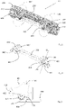
- figure 1 shows a locking unit 10 according to the present invention with two locking devices 100, 100 '(dashed ovals), which are held by a common support structure 200.
- the grip element 300 is in figure 1 something obscured; designates the common recessed grip 310, which is arranged centrally between the locking devices 100, 100'.
- a plurality of fastening holes 230, 230' are shown on the supporting structure 200, with the aid of which the supporting structure can be screwed or riveted to a flap.
- the representation of the preassembled (ready-to-install) locking unit is here "from behind", ie from the side facing away from the user.
- the spatially very compact locking device (100 or 100') shows the plain bearing bushing 220 here, the plain bearing bolt 320 guided in it is not visible.
- the pawl 400 is mounted in the supporting structure 200 by means of the rotary bolt 500 .
- figure 2 shows the arrangement figure 1 without the support structure 200.
- the main components are therefore the handle element 300 and the pawl 400 with their respective built-in components in the picture.
- the inside figure 1 invisible plain bearing bolt 320 which ensures the forced straight guidance in conjunction with the plain bearing bushing 220, can be clearly seen.
- As a molded component it is connected to the handle element 300 via a web.
- the pawl 400 is shown to the side (in the picture to the left of the grip element 300, to the right of the grip element 300').
- the connection between the pawl 400 and the handle element 300 takes place via the activation bolt 510 (somewhat concealed).
- the rotation bolt 500 marks the pivot axis about which the pawl can move during the opening and closing process.
- figure 3 is a cross section through the configuration shown in figure 2 , roughly along the line labeled L1.
- the pawl 400 is shown with its hook 410 against the background of the handle element 300.
- the connecting link 420 which guides the activation bolt 510, is clearly visible.
- the backdrop has two end (stop) positions 421, 422 for the activation bolt 510.
- the activation bolt 510 can move and remain in the backdrop.
- the indicator 340 which is designed here as a projection or lip and—depending on the position—can protrude in front of the outer surface of the support structure 200 or the flap, thus indicating that the flap is not securely closed.
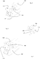
- figure 6 basically shows a locking device 100 without a support structure 200, ie analogous to figure 2 , just from a different perspective.
- figure 4 shows the handle element 300 alone, figure 5 the pawl 400 with link 420 and the two elements activation bolt 510 and rotation bolt 500.
- figure 4 shows the plain bearing bolt 320 and the recessed grip 310.
- the gap is provided for the pawl 400, the receptacles 330 are provided for the activation bolt 510.
- the projection of the grip element 300 serves as an indicator 340.
- FIG 6 shows the connected state of the pawl 400 and the handle element 300.
- the pawl 400 is connected to the handle element via the activation bolt 510 and the link 420 (concealed). Rotation pin 500 is shown, it would be stored in the support structure 200 not shown here.
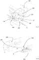
- figure 7 shows an oblique view of the support structure 200 with the handle element 300 without the pawl 400, along a cross section through the plain bearing bushing 220/the plain bearing pin 320 along the displacement axis thereof.
- This is in Figure 7 and 8 marked with L2.
- the plain bearing pin 320 has been fully inserted into the plain bearing bushing 220 .
- the arrangement of the receptacles 330 along the axis L3, which describes the position of the activation bolt 510 provided, can be clearly seen.
- L2 and L3 in space perpendicular to each other.
- Reference number 210 refers to the pivot bearing 210 for the (omitted) pawl 400.
- figure 8 shows the elements figure 7 in the exploded state; the axis L2 of plain bearing bushing 220 and plain bearing bolt 320 is marked, as is the axis L3 arranged perpendicular thereto.
Landscapes
- Engineering & Computer Science (AREA)
- Mechanical Engineering (AREA)
- Aviation & Aerospace Engineering (AREA)
- Lock And Its Accessories (AREA)
Abstract
Die Führung des Griffelements (200) erfolgt beim Öffnen und Schliessen durch die Kombination Gleitlagerbolzen (320) / Gleitlagerbuchse (220) geradlinig und diese Gerad-Bewegung wird durch einen mitbewegten Aktivierungsbolzen (510) über die Kulisse (420) in eine Drehbewegung der Klinke (400) übersetzt, welche die Entriegelung der Sperrvorrichtung bewirkt.
Description
- Die vorliegende Erfindung befasst sich mit einer Sperrvorrichtung, d.h. einem Schliesselement für eine Klappe. Eine oder mehrere solche Sperrvorrichtungen können zu einer Schliesseinheit kombiniert werden. Die hier beschriebene Sperrvorrichtung und Schliesseinheit sind für die Handbetätigung vorgesehen. Die Hauptanwendung sind Gepäckfächer in Flugzeugen, die im Überkopf-Bereich über den Sitzen vorgesehen sind.
- Gepäckfächer in Flugzeugen sind vermutlich die von einem Passagier meistbeanspruchte Komponente eines Flugzeugs. Sie müssen daher sowohl in der Bedienung einfach als auch sicher sein, um ein Herausfallen von Gepäck in ungünstigen Flugsituationen sicher zu verhindern. Dazu ist es entscheidend, dass die Klappen, die die Gepäckfächer verschliessen, auch tatsächlich verschlossen und nicht nur teilweise eingerastet sind und sich im Flug unbeabsichtigt öffnen. Um dem Flugpersonal die Kontrolle des korrekten Verschlusses zu erleichtern, ist es wünschenswert, ein optisch auffallendes, manipulationssicheres Element an jeder Schliesseinheit zu haben, also einen Indikator für den korrekten, verschlossenen Zustand.
- Es ist eine Vielzahl von gängigen Lösungen mit Rast-, Schnapp- und Bolzenverschlüssen bekannt. Die meisten sind mechanisch relativ komplex, erfordern eine sorgfältige Justage vor Ort und erlauben - wenn überhaupt - nur mit zusätzlichen Mitteln eine Anzeige des Zustandes "korrekt verschlossen". Es ist Aufgabe der vorliegenden Erfindung, eine einfache, kompakte und mechanisch unaufwändige Lösung für die oben beschriebenen Probleme vorzuschlagen.
- Die oben beschriebene Aufgabe der Erfindung wird durch die Merkmale des unabhängigen Anspruchs 1 gelöst.
Mit dem Begriff Sperrvorrichtung wird im Folgenden die kleinste Kombination von technischen Merkmalen beschrieben, die, wenn an einer Klappe oder Türe angebracht, ein sicheres Öffnen und Schliessen im obigen Sinne bewirken kann. Eine Schliesseinheit ist eine Baugruppe, die mindestens zwei Sperrvorrichtungen beinhaltet, die aber gemeinsam betätigt werden. Dabei können einzelne technische Merkmale zusammengefasst sein. So lässt sich das erfinderische Prinzip mit einem Handgriff und einer Sperrvorrichtung realisieren, hier spezifisch einer Klinke mit Haken. Es lassen sich jedoch auch zwei Klinken / Haken mit einem Handgriff betätigen, ohne die erfinderische Grundidee zu verlassen. - Eine erfindungsgemässe Sperrvorrichtung für eine Klappe bzw. eine Türe umfasst im Grundsatz drei technische Elemente: eine im Wesentlichen flächige Tragstruktur, ein Griffelement zum Entriegeln der Sperrvorrichtung; sowie eine Klinke mit einem Haken.
- Die Tragstruktur stellt dabei eine Art Montagerahmen der an oder mit der Klappe bzw. Türe (auch in einer Aussparung derselben) kraftschlüssig verbunden werden kann. Die Tragstruktur kann Aussteifungen, Rippen wie auch dekorative Elemente enthalten, soweit der geplante Einsatz dies erfordert. In der Tragstruktur sind als wesentliche technische Merkmale integriert: ein Drehlager für einen Rotationsbolzen sowie mindestens eine zylinderförmige geradführende Gleitlagerbuchse.
- Das Griffelement wiederum weist eine Griffmulde (als Eingriffsmöglichkeit für einen Bediener) und mindestens einen Gleitlagerbolzen auf. Letztere ist so dimensioniert, dass er in die vorerwähnte Gleitlagerbuchse beweglich geführt werden kann. Ferner ist im Griffelement eine Aufnahme für einen ortsfest im Griffelement angeordneten, rechtwinklig zum Gleitlagerbolzen ausgerichteten Aktivierungsbolzen vorgesehen.
- Eine Klinke stellt nach üblicher Definition ein Maschinenteil dar, das über einen einarmigen, um einen Zapfen drehbar gelagerten kurzen Hebel verfügt, der dann dazu dient, ein anderes Maschinenteil in seiner Bewegung zu hemmen. Im vorliegenden Fall weist die Klinke einen Haken auf, ein Lager für den Rotationsbolzen und eine als Langloch oder Nut ausgeführte Kulisse zur Führung des Aktivierungsbolzens.
- Diese drei technischen Elemente werden vormontiert, wobei Tragstruktur und Griffelement so miteinander verbunden werden, dass der Gleitlagerbolzen des Griffelements (und damit auch das Griffelement selbst) in der Gleitlagerbuchse der Tragstruktur längsverschieblich (zwangs-)geführt wird. Die Klinke ist im Drehlager der Tragstruktur um den Rotationsbolzen drehbar gelagert und erlaubt der Klinke eine Bewegung zwischen einer Position "verriegelt" und "offen". Dabei befindet sich der Aktivierungsbolzen sich im Eingriff mit der Kulisse.
- Zusammengefasst sind die drei technischen Elemente Tragstruktur, Griffelement und Klinke über (a) die Gleitlagerung von Griffelement und Tragstruktur, sowie über (b) den Rotationsbolzen und (c) den Aktivierungsbolzen miteinander verbunden. Während der Rotationsbolzen das Hebelende der Klinke in der Tragstruktur fest hält, wird die Klinke durch das Griffelement über die Kulisse geführt. Durch die als Langloch ausgeführte Kulisse wird dabei keine durch einen Formschluss erzwungene, instantane Mitbewegung erzwungen. Vielmehr erfolgt die Führung des Griffelements beim Öffnen (und Schliessen) durch die Kombination Gleitlagerbolzen / Gleitlagerbuchse geradlinig und diese Gerad-Bewegung wird durch den mitbewegten Aktivierungsbolzen über die Kulisse in eine Drehbewegung der Klinke übersetzt wird, welche die Entriegelung der Sperrvorrichtung bewirkt. Der Weg, den der Aktivierungsbolzen in der Kulisse dabei zurücklegen kann, bewirkt ein Spiel bzw. einen Zeitversatz zwischen Beginn der Öffnungsbewegung (= Ziehen des Handgriffs) und dem Einsetzen des eigentlichen Entriegelns.
- Die Sperrvorrichtung kann durch eine Schenkelfeder am Drehlager ergänzt werden, welche die Klinke in Richtung der Position drückt.
- In einer Weiterbildung der Erfindung kann am Griffelement ein Indikator angebracht sein, der sichtbar ist, wenn die Sperrvorrichtung sich in der einer "Offen" Position befindet und nur verdeckt wird, wenn die Sperrvorrichtung sich in der einer "Geschlossen" Position befindet. In seiner Funktion als Sicherungselement bleibt der Indikator bei Fehlbetätigung der Klinke somit zwangsläufig sichtbar. Der Indikator kann als eine vorspringende flache Zunge oder als Farbmarkierung am Handgriff vorgesehen werden.
- Die beschriebene Sperrvorrichtung kann weiterhin so ausgeführt werden, dass die Kulisse eine erste und eine zweite Endposition besitzt und der Aktivierungsbolzen zwischen der ersten und zweiten Endposition beweglich ist und der Öffnungsvorgang erst durch das kraftschlüssige Anliegen in der ersten Endposition eingeleitet wird. Auf diese Weise wird das oben beschriebene Spiel bzw. der Zeitversatz erreicht.
- Die Sperrvorrichtung kann so ausgelegt sein, dass beim Schliessvorgang der Haken in einen Gegenhalter einrastet und dadurch über die Kulisse der Aktivierungsbolzen von einer nicht definierten Position in der Kulisse an die erste Endposition gezogen wird und das Griffelement in eine definierte Endposition überführt wird. Der Gegenhalter wird so ausgelegt, dass er die in die entsprechenden Aussparungen des Hakens eingreifen kann
- Wie oben erwähnt können zwei Sperrvorrichtungen zu einer Schliesseinheit kombiniert werden, wobei die beiden Griffelemente um eine gemeinsame Griffmulde angeordnet sind und eine gemeinsame Tragstruktur für beiden Sperrvorrichtungen realisiert wird.
- Der Betätigungsvorgang für die erfinderische Sperrvorrichtung bzw. Schliesseinheit kann als Verfahren zum Öffnen einer geschlossenen Klappe beschrieben werden, mit folgenden Schritten:
- Das Betätigen des Griffelementes durch Ziehen an der Griffmulde.
- Dadurch wird die Klinke betätigt und der Haken gibt seinen Gegenhalter frei. Die Sperrvorrichtung bzw. die Schliesseinheit ist entriegelt, die Klappe kann geöffnet werden.
- Der Aktivierungsbolzen kann auf einer undefinierten Position in der Kulisse verbleiben, wobei jedoch der Indikator für die Position "Offen" sichtbar ist. Dies wird erreicht, weil der Indikator nur in der definierten Endposition "Geschlossen" nicht mehr auf eine mögliche Fehlbetätigung aufmerksam macht.
-
-
Figur 1 zeigt eine Schliesseinheit mit 2 Sperrvorrichtungen. -
Figur 2 zeigt dieselbe Schliesseinheit ohne die Tragstruktur. -
Figur 3 zeigt einen Schnitt durch die Darstellung derFigur 3 etwa entlang der Linie ausFigur 2 , in Seitenansicht auf die Klinke. -
Figur 4 zeigt eine Schrägansicht auf ein Griffelement -
Figur 5 zeigt eine Klinke mit Haken und zwei Bolzen -
Figur 6 zeigt eine Kombination ausFigur 4 und 5 -
Figur 7 zeigt die Orientierung verschiedener Verbindungselemente zwischen Tragstruktur und Griffelement -
Figur 8 zeigt die Tragstruktur und Griffelement aus anderer Perspektive. - In einigen Figuren werden Merkmale mit einem Hochstrich ' beim Referenzzeichen gekennzeichnet. Funktionell und strukturell entsprechen diese dem Merkmal ohne Hochstrich und werden daher nicht jedes Mal separat erläutert.
-
Figur 1 zeigt eine Schliesseinheit 10 gemäss vorliegender Erfindung mit zwei Sperrvorrichtungen 100, 100' (gestrichelte Ovale), die von einer gemeinsamen Tragstruktur 200 gehalten werden. Das Griffelement 300 ist inFigur 1 etwas verdeckt; bezeichnet ist die gemeinsame Griffmulde 310, die mittig zwischen den Sperrvorrichtungen 100,100' angeordnet ist. An der Tragstruktur 200 sind mehrere Befestigungslöcher 230, 230' gezeigt, mit deren Hilfe die Tragstruktur an einer Klappe verschraubt oder vernietet werden kann. Die Darstellung der vormontierten (einbaufertigen) Schliesseinheit ist hier "von hinten", das heisst von der dem Benutzer abgewandten Seite. Die räumlich sehr kompakte Sperrvorrichtung (100 bzw. 100') zeigt hier die Gleitlagerbuchse 220, der darin geführte Gleitlagerbolzen 320 ist nicht sichtbar. Die Klinke 400 ist mittels des Rotationsbolzens 500 in der Tragstruktur 200 gelagert. -
Figur 2 zeigt die Anordnung ausFigur 1 ohne die Tragstruktur 200. Als Hauptkomponenten sind somit das Griffelement 300 und die Klinke 400 mit ihren jeweiligen, verbauten Bestandteilen im Bild. Der inFigur 1 unsichtbare Gleitlagerbolzen 320, der für die erzwungene Geradführung im Zusammenspiel mit der Gleitlagerbuchse 220 sorgt, ist deutlich erkennbar. Er ist als angeformtes Bauteil über einen Steg mit dem Griffelement 300 verbunden. Seitlich daneben (im Bild links vom Griffelement 300, rechts vom Griffelement 300') ist die Klinke 400 gezeigt. Die Verbindung zwischen Klinke 400 und Griffelement 300 erfolgt über den Aktivierungsbolzen 510 (etwas verdeckt). Der Rotationsbolzen 500 markiert die Schwenkachse, um die die Klinke sich beim Öffnungs- und Schliessvorgang beweglich ist. -
Figur 3 ist ein Querschnitt durch die Konfiguration gezeigt inFigur 2 , etwa entlang der als L1 bezeichneten Linie. Gezeigt ist die Klinke 400 mit ihrem Haken 410 vor dem Hintergrund des Griffelementes 300. Deutlich erkennbar ist die Kulisse 420, die den Aktivierungsbolzen 510 führt. Die Kulisse weist zwei End(anschlags-)positionen 421, 422 auf für den Aktivierungsbolzen 510. Je nach Betätigungszustand der Sperrvorrichtung kann der Aktivierungsbolzen 510 sich in der Kulisse bewegen und auch verbleiben. Im Bild sichtbar ist auch der Indikator 340, der hier als Vorsprung oder Lippe ausgebildet ist und - je nach - Lage vor die Aussenfläche der Tragstruktur 200 bzw. der Klappe herausragen kann und somit die anzeigt, dass die Klappe nicht sicher geschlossen ist. - Die
Figuren 4, 5 und 6 werden im Zusammenhang erläutert.Figur 6 zeigt grundsätzlich eine Sperrvorrichtung 100 ohne Tragstruktur 200, also analog zuFigur 2 , nur aus anderer Perspektive.Figur 4 zeigt dabei das Griffelement 300 allein,Figur 5 die Klinke 400 mit Kulisse 420 und den beiden Elementen Aktivierungsbolzen 510 und Rotationsbolzen 500. -
Figur 4 zeigt den Gleitlagerbolzen 320 und die Griffmulde 310. Der Zwischenraum ist für die Klinke 400 vorgesehen, die Aufnahmen 330 sind für den Aktivierungsbolzen 510 vorgesehen. Der Vorsprung der Griffelements 300 dient als Indikator 340. -
Figur 6 zeigt den verbundenen Zustand aus Klinke 400 und Griffelement 300. Die Klinke 400 ist via Aktivierungsbolzen 510 und die Kulisse 420 (verdeckt) mit dem Griffelement verbunden. Rotationsbolzen 500 ist gezeigt, er wäre in der hier nicht gezeigten Tragstruktur 200 gelagert. -
Figur 7 zeigt eine Schrägansicht auf die Tragstruktur 200 mit dem Griffelement 300 ohne Klinke 400, entlang eines Querschnitts durch die Gleitlagerbuchse 220 / den Gleitlagerbolzen 320 entlang deren Verschiebungsachse. Diese ist inFigur 7 und 8 mit L2 markiert. Der Gleitlagerbolzen 320 ist vollständig in die Gleitlagerbuchse 220 eingeschoben. Deutlich erkennbar ist die Anordnung der Aufnahmen 330 entlang der Achse L3, die die Lage des vorgesehenen Aktivierungsbolzens 510 beschreibt. Wie aus der Zeichnung ersichtlich, liegen L2 und L3 im Raum rechtwinklig zueinander. Referenzzeichen 210 verweist auf das Drehlager 210 für die (weggelassene) Klinke 400.Figur 8 zeigt die Elemente ausFigur 7 im explodierten Zustand; die Achse L2 von Gleitlagerbuchse 220 und Gleitlagerbolzen 320 ist markiert, ebenso die senkrecht dazu angeordnete Achse L3.
Claims (9)
- Sperrvorrichtung (100) für eine Klappe bzw. eine Türe umfassend
eine im Wesentlichen flächige Tragstruktur (200),
ein Griffelement (300) zum Entriegeln der Sperrvorrichtung; sowie
eine Klinke (400) mit einem Haken (410); wobei:die Tragstruktur (200) mit der Klappe kraftschlüssig verbunden werden kann und- ein Drehlager (210) für einen Rotationsbolzen (500); sowie- mindestens eine zylinderförmige geradführende Gleitlagerbuchse (220) aufweist;das Griffelement (300)- eine Griffmulde (310) und mindestens einen Gleitlagerbolzen (320) aufweist und- eine Aufnahme (330) für einen ortsfest im Griffelement (300) angeordneten, rechtwinklig zum Gleitlagerbolzen ausgerichteten Aktivierungsbolzen (510) bietet;die Klinke (400)- eine als Langloch oder Nut ausgeführte Kulisse (420) aufweist zur Führung des Aktivierungsbolzens (510);wobei in einem vormontierten Zustand- der Gleitlagerbolzen (320) des Griffelements (300) in der Gleitlagerbuchse (220) der Tragstruktur (200) längsverschieblich geführt ist;- die Klinke (400) im Drehlager (210) der Tragstruktur (200) um den Rotationsbolzen (500) drehbar gelagert ist zwischen einer Position "verriegelt" und "offen"; und- der Aktivierungsbolzen (510) sich im Eingriff mit der Kulisse (420) befindetdadurch gekennzeichnet, dassdie Führung des Griffelements (200) beim Öffnen und Schliessen durch die Kombination Gleitlagerbolzen (320) / Gleitlagerbuchse (220) geradlinig erfolgt und diese Gerad-Bewegung durch den mitbewegten Aktivierungsbolzen (510) über die Kulisse (420) in eine Drehbewegung der Klinke (400) übersetzt wird, welche die Entriegelung der Sperrvorrichtung bewirkt. - Sperrvorrichtung nach Anspruch 1, dadurch gekennzeichnet, dass eine Schenkelfeder (520) am Drehlager (210) vorgesehen ist, welche die Klinke (400) in Richtung der Position "verriegelt" drückt.
- Sperrvorrichtung nach Anspruch 1 -2, dadurch gekennzeichnet, dass am Griffelement (300) ein Indikator (340) angebracht ist, der sichtbar ist, wenn die Sperrvorrichtung sich in der einer "Offen" Position befindet und der verdeckt wird, wenn die Sperrvorrichtung sich in der einer "Geschlossen" Position befindet.
- Sperrvorrichtung nach Anspruch 1 - 3, dadurch gekennzeichnet, dass die Kulisse (420) eine erste (421) und eine zweite Endposition (422) besitzt und der Aktivierungsbolzen zwischen der ersten und zweiten Endposition (421, 422) beweglich ist und der Öffnungsvorgang erst durch das kraftschlüssige Anliegen in der ersten Endposition eingeleitet wird.
- Sperrvorrichtung nach Anspruch 1 - 4, dadurch gekennzeichnet, dass beim Schliessvorgang der Haken (410) in einen Gegenhalter einrastet und dadurch über die Kulisse (420) der Aktivierungsbolzen (510) von einer nicht definierten Position in der Kulisse (420) an die erste Endposition (421) gezogen wird und das Griffelement (300) in eine definierte Endposition überführt wird.
- Schliesseinheit (10) für eine Klappe bzw. eine Türe umfassend zwei Sperrvorrichtungen (100, 100') nach Anspruch 1 - 5 dadurch gekennzeichnet, dass die beiden Griffelemente (300, 300') um eine gemeinsame Griffmulde (310) angeordnet sind und eine gemeinsame Tragstruktur (200) vorgesehen wird.
- Verfahren zum Öffnen einer geschlossenen Klappe mit einer Schliesseinheit nach Anspruch 6 bzw. einer Sperrvorrichtung nach Anspruch 1-5, mit folgenden Schritten:- Betätigen des Griffelementes (310) durch Ziehen an der Griffmulde (310),- wodurch die Klinke (400) betätigt wird und der Haken (410) seinen Gegenhalter freigibt und- der Aktivierungsbolzen (510) auf einer undefinierten Position in der Kulisse (420) verbleibt und- der Indikator (340) sichtbar wird.
- Verfahren zum Schliessen einer geöffneten Klappe mit einer Schliesseinheit nach Anspruch 6 bzw. einer Sperrvorrichtung nach Anspruch 1-5, mit folgenden Schritten:- Drücken der Klappe in Schliessrichtung an der Klappe selbst oder an der Sperrvorrichtung / Schliesseinheit,- Bis der Haken (410) an einen Gegenhalter anschlägt und durch die weitere Drehbewegung um das Drehlager (210) in den Gegenhalter einrastet,- Wobei durch die Einrastbewegung gleichzeitig der Aktivierungsbolzen (510) das Grifffelement (300) in eine definierte "Geschlossen" Position zwingt und- der Indikator (340) verdeckt wird.
- Verwendung einer Schliesseinheit nach Anspruch 1 bis 5 bzw. einer Schliesseinheit nach Anspruch 6 für eine Klappe bzw. eine Türe in einem Gepäckfach in einem Flugzeug.
Priority Applications (1)
| Application Number | Priority Date | Filing Date | Title |
|---|---|---|---|
| EP21156064.4A EP4039595B1 (de) | 2021-02-09 | 2021-02-09 | Sperrvorrichtung und schliesseinheit für eine klappe |
Applications Claiming Priority (1)
| Application Number | Priority Date | Filing Date | Title |
|---|---|---|---|
| EP21156064.4A EP4039595B1 (de) | 2021-02-09 | 2021-02-09 | Sperrvorrichtung und schliesseinheit für eine klappe |
Publications (2)
| Publication Number | Publication Date |
|---|---|
| EP4039595A1 true EP4039595A1 (de) | 2022-08-10 |
| EP4039595B1 EP4039595B1 (de) | 2024-07-24 |
Family
ID=74586764
Family Applications (1)
| Application Number | Title | Priority Date | Filing Date |
|---|---|---|---|
| EP21156064.4A Active EP4039595B1 (de) | 2021-02-09 | 2021-02-09 | Sperrvorrichtung und schliesseinheit für eine klappe |
Country Status (1)
| Country | Link |
|---|---|
| EP (1) | EP4039595B1 (de) |
Citations (2)
| Publication number | Priority date | Publication date | Assignee | Title |
|---|---|---|---|---|
| EP1197621A1 (de) * | 2000-10-14 | 2002-04-17 | Schwarz Verbindungs-Systeme GmbH | Verriegelungsanordnung für ein Gepäckfach |
| US20030146629A1 (en) * | 2002-02-05 | 2003-08-07 | Cheever John E. | Overhead storage bin lock |
-
2021
- 2021-02-09 EP EP21156064.4A patent/EP4039595B1/de active Active
Patent Citations (2)
| Publication number | Priority date | Publication date | Assignee | Title |
|---|---|---|---|---|
| EP1197621A1 (de) * | 2000-10-14 | 2002-04-17 | Schwarz Verbindungs-Systeme GmbH | Verriegelungsanordnung für ein Gepäckfach |
| US20030146629A1 (en) * | 2002-02-05 | 2003-08-07 | Cheever John E. | Overhead storage bin lock |
Also Published As
| Publication number | Publication date |
|---|---|
| EP4039595B1 (de) | 2024-07-24 |
Similar Documents
| Publication | Publication Date | Title |
|---|---|---|
| EP0653010B1 (de) | Sperrvorrichtung für türen eines kraftfahrzeugs | |
| EP2581531B1 (de) | Getriebe für einen Treibstangenbeschlag eines Fensters, einer Tür oder dergleichen | |
| EP4097318B1 (de) | Elektrisch betätigbares kraftfahrzeugschloss | |
| EP2138656A2 (de) | Türaußengriff, insbesondere für Fahrzeuge | |
| DE102019115304A1 (de) | Aufstellvorrichtung für ein Kraftfahrzeugtürelement | |
| EP2562338A2 (de) | Türgriffanordnung eines Kraftfahrzeugs | |
| DE102019112398A1 (de) | Aufstellvorrichtung für ein Kraftfahrzeugtürelement | |
| DE102017216920A1 (de) | Türgriffeinrichtung für eine Tür eines Kraftfahrzeugs, Tür, Kraftfahrzeug | |
| DE19806154C2 (de) | Kraftfahrzeugtürverschluß | |
| DE29619007U1 (de) | Verriegelungsvorrichtung | |
| EP3060424B1 (de) | Verriegelungsanzeige für einen fahrzeugsitz, fahrzeugsitz, kraftfahrzeug und verfahren zum verriegeln eines fahrzeugsitzes | |
| EP4039595B1 (de) | Sperrvorrichtung und schliesseinheit für eine klappe | |
| EP3445933B1 (de) | Zuziehhilfe für kraftfahrzeuge | |
| DE202007000733U1 (de) | Kraftfahrzeugschloß | |
| EP3963158B1 (de) | Verschluss für ein fenster, eine tür oder dergleichen | |
| DE102017127386A1 (de) | Kraftfahrzeugschloss | |
| DE2839760A1 (de) | Verriegelungsvorrichtung, insbesondere fuer tueren oder fenster | |
| DE1428501C3 (de) | Haubenverschluß, insbesondere für Kraftfahrzeuge | |
| AT392819B (de) | Schloss, insbesondere panikschloss | |
| DE3419543C2 (de) | Verschluß für Seitentüren von Kraftfahrzeugen | |
| DE19916223C1 (de) | Entriegelungseinrichtung für eine klappbare Rückenlehne eines Kraftfahrzeug-Rücksitzes | |
| DE19530723A1 (de) | Motorhaubenverschlußeinrichtung | |
| DE102020204593A1 (de) | Kabinentüranordnung für einen aufzug mit einer mechanischen kabinentürverriegelung | |
| DE102024203222B3 (de) | Beschlaganordnung für ein Fenster, eine Tür oder dergleichen zur Betätigung einer Feststellbremse | |
| DE102010041743B4 (de) | Schloss für eine Tür oder Klappe eines Fahrzeugs |
Legal Events
| Date | Code | Title | Description |
|---|---|---|---|
| PUAI | Public reference made under article 153(3) epc to a published international application that has entered the european phase |
Free format text: ORIGINAL CODE: 0009012 |
|
| STAA | Information on the status of an ep patent application or granted ep patent |
Free format text: STATUS: THE APPLICATION HAS BEEN PUBLISHED |
|
| AK | Designated contracting states |
Kind code of ref document: A1 Designated state(s): AL AT BE BG CH CY CZ DE DK EE ES FI FR GB GR HR HU IE IS IT LI LT LU LV MC MK MT NL NO PL PT RO RS SE SI SK SM TR |
|
| STAA | Information on the status of an ep patent application or granted ep patent |
Free format text: STATUS: REQUEST FOR EXAMINATION WAS MADE |
|
| 17P | Request for examination filed |
Effective date: 20230210 |
|
| RBV | Designated contracting states (corrected) |
Designated state(s): AL AT BE BG CH CY CZ DE DK EE ES FI FR GB GR HR HU IE IS IT LI LT LU LV MC MK MT NL NO PL PT RO RS SE SI SK SM TR |
|
| GRAP | Despatch of communication of intention to grant a patent |
Free format text: ORIGINAL CODE: EPIDOSNIGR1 |
|
| STAA | Information on the status of an ep patent application or granted ep patent |
Free format text: STATUS: GRANT OF PATENT IS INTENDED |
|
| RIC1 | Information provided on ipc code assigned before grant |
Ipc: E05B 41/00 20060101ALI20240125BHEP Ipc: B64D 11/00 20060101AFI20240125BHEP |
|
| INTG | Intention to grant announced |
Effective date: 20240214 |
|
| GRAS | Grant fee paid |
Free format text: ORIGINAL CODE: EPIDOSNIGR3 |
|
| GRAA | (expected) grant |
Free format text: ORIGINAL CODE: 0009210 |
|
| STAA | Information on the status of an ep patent application or granted ep patent |
Free format text: STATUS: THE PATENT HAS BEEN GRANTED |
|
| AK | Designated contracting states |
Kind code of ref document: B1 Designated state(s): AL AT BE BG CH CY CZ DE DK EE ES FI FR GB GR HR HU IE IS IT LI LT LU LV MC MK MT NL NO PL PT RO RS SE SI SK SM TR |
|
| REG | Reference to a national code |
Ref country code: GB Ref legal event code: FG4D Free format text: NOT ENGLISH |
|
| REG | Reference to a national code |
Ref country code: CH Ref legal event code: EP |
|
| REG | Reference to a national code |
Ref country code: DE Ref legal event code: R096 Ref document number: 502021004446 Country of ref document: DE |
|
| REG | Reference to a national code |
Ref country code: IE Ref legal event code: FG4D Free format text: LANGUAGE OF EP DOCUMENT: GERMAN |
|
| REG | Reference to a national code |
Ref country code: LT Ref legal event code: MG9D |
|
| REG | Reference to a national code |
Ref country code: NL Ref legal event code: MP Effective date: 20240724 |
|
| PG25 | Lapsed in a contracting state [announced via postgrant information from national office to epo] |
Ref country code: PT Free format text: LAPSE BECAUSE OF FAILURE TO SUBMIT A TRANSLATION OF THE DESCRIPTION OR TO PAY THE FEE WITHIN THE PRESCRIBED TIME-LIMIT Effective date: 20241125 |
|
| PG25 | Lapsed in a contracting state [announced via postgrant information from national office to epo] |
Ref country code: NL Free format text: LAPSE BECAUSE OF FAILURE TO SUBMIT A TRANSLATION OF THE DESCRIPTION OR TO PAY THE FEE WITHIN THE PRESCRIBED TIME-LIMIT Effective date: 20240724 |
|
| PG25 | Lapsed in a contracting state [announced via postgrant information from national office to epo] |
Ref country code: PT Free format text: LAPSE BECAUSE OF FAILURE TO SUBMIT A TRANSLATION OF THE DESCRIPTION OR TO PAY THE FEE WITHIN THE PRESCRIBED TIME-LIMIT Effective date: 20241125 Ref country code: NL Free format text: LAPSE BECAUSE OF FAILURE TO SUBMIT A TRANSLATION OF THE DESCRIPTION OR TO PAY THE FEE WITHIN THE PRESCRIBED TIME-LIMIT Effective date: 20240724 |
|
| PG25 | Lapsed in a contracting state [announced via postgrant information from national office to epo] |
Ref country code: NO Free format text: LAPSE BECAUSE OF FAILURE TO SUBMIT A TRANSLATION OF THE DESCRIPTION OR TO PAY THE FEE WITHIN THE PRESCRIBED TIME-LIMIT Effective date: 20241024 |
|
| PG25 | Lapsed in a contracting state [announced via postgrant information from national office to epo] |
Ref country code: FI Free format text: LAPSE BECAUSE OF FAILURE TO SUBMIT A TRANSLATION OF THE DESCRIPTION OR TO PAY THE FEE WITHIN THE PRESCRIBED TIME-LIMIT Effective date: 20240724 Ref country code: PL Free format text: LAPSE BECAUSE OF FAILURE TO SUBMIT A TRANSLATION OF THE DESCRIPTION OR TO PAY THE FEE WITHIN THE PRESCRIBED TIME-LIMIT Effective date: 20240724 Ref country code: GR Free format text: LAPSE BECAUSE OF FAILURE TO SUBMIT A TRANSLATION OF THE DESCRIPTION OR TO PAY THE FEE WITHIN THE PRESCRIBED TIME-LIMIT Effective date: 20241025 |
|
| PG25 | Lapsed in a contracting state [announced via postgrant information from national office to epo] |
Ref country code: BG Free format text: LAPSE BECAUSE OF FAILURE TO SUBMIT A TRANSLATION OF THE DESCRIPTION OR TO PAY THE FEE WITHIN THE PRESCRIBED TIME-LIMIT Effective date: 20240724 |
|
| PG25 | Lapsed in a contracting state [announced via postgrant information from national office to epo] |
Ref country code: LV Free format text: LAPSE BECAUSE OF FAILURE TO SUBMIT A TRANSLATION OF THE DESCRIPTION OR TO PAY THE FEE WITHIN THE PRESCRIBED TIME-LIMIT Effective date: 20240724 |
|
| PG25 | Lapsed in a contracting state [announced via postgrant information from national office to epo] |
Ref country code: IS Free format text: LAPSE BECAUSE OF FAILURE TO SUBMIT A TRANSLATION OF THE DESCRIPTION OR TO PAY THE FEE WITHIN THE PRESCRIBED TIME-LIMIT Effective date: 20241124 |
|
| PG25 | Lapsed in a contracting state [announced via postgrant information from national office to epo] |
Ref country code: HR Free format text: LAPSE BECAUSE OF FAILURE TO SUBMIT A TRANSLATION OF THE DESCRIPTION OR TO PAY THE FEE WITHIN THE PRESCRIBED TIME-LIMIT Effective date: 20240724 |
|
| PG25 | Lapsed in a contracting state [announced via postgrant information from national office to epo] |
Ref country code: ES Free format text: LAPSE BECAUSE OF FAILURE TO SUBMIT A TRANSLATION OF THE DESCRIPTION OR TO PAY THE FEE WITHIN THE PRESCRIBED TIME-LIMIT Effective date: 20240724 Ref country code: RS Free format text: LAPSE BECAUSE OF FAILURE TO SUBMIT A TRANSLATION OF THE DESCRIPTION OR TO PAY THE FEE WITHIN THE PRESCRIBED TIME-LIMIT Effective date: 20241024 |
|
| PG25 | Lapsed in a contracting state [announced via postgrant information from national office to epo] |
Ref country code: RS Free format text: LAPSE BECAUSE OF FAILURE TO SUBMIT A TRANSLATION OF THE DESCRIPTION OR TO PAY THE FEE WITHIN THE PRESCRIBED TIME-LIMIT Effective date: 20241024 Ref country code: PL Free format text: LAPSE BECAUSE OF FAILURE TO SUBMIT A TRANSLATION OF THE DESCRIPTION OR TO PAY THE FEE WITHIN THE PRESCRIBED TIME-LIMIT Effective date: 20240724 Ref country code: NO Free format text: LAPSE BECAUSE OF FAILURE TO SUBMIT A TRANSLATION OF THE DESCRIPTION OR TO PAY THE FEE WITHIN THE PRESCRIBED TIME-LIMIT Effective date: 20241024 Ref country code: LV Free format text: LAPSE BECAUSE OF FAILURE TO SUBMIT A TRANSLATION OF THE DESCRIPTION OR TO PAY THE FEE WITHIN THE PRESCRIBED TIME-LIMIT Effective date: 20240724 Ref country code: IS Free format text: LAPSE BECAUSE OF FAILURE TO SUBMIT A TRANSLATION OF THE DESCRIPTION OR TO PAY THE FEE WITHIN THE PRESCRIBED TIME-LIMIT Effective date: 20241124 Ref country code: HR Free format text: LAPSE BECAUSE OF FAILURE TO SUBMIT A TRANSLATION OF THE DESCRIPTION OR TO PAY THE FEE WITHIN THE PRESCRIBED TIME-LIMIT Effective date: 20240724 Ref country code: GR Free format text: LAPSE BECAUSE OF FAILURE TO SUBMIT A TRANSLATION OF THE DESCRIPTION OR TO PAY THE FEE WITHIN THE PRESCRIBED TIME-LIMIT Effective date: 20241025 Ref country code: FI Free format text: LAPSE BECAUSE OF FAILURE TO SUBMIT A TRANSLATION OF THE DESCRIPTION OR TO PAY THE FEE WITHIN THE PRESCRIBED TIME-LIMIT Effective date: 20240724 Ref country code: ES Free format text: LAPSE BECAUSE OF FAILURE TO SUBMIT A TRANSLATION OF THE DESCRIPTION OR TO PAY THE FEE WITHIN THE PRESCRIBED TIME-LIMIT Effective date: 20240724 Ref country code: BG Free format text: LAPSE BECAUSE OF FAILURE TO SUBMIT A TRANSLATION OF THE DESCRIPTION OR TO PAY THE FEE WITHIN THE PRESCRIBED TIME-LIMIT Effective date: 20240724 |
|
| PG25 | Lapsed in a contracting state [announced via postgrant information from national office to epo] |
Ref country code: RO Free format text: LAPSE BECAUSE OF FAILURE TO SUBMIT A TRANSLATION OF THE DESCRIPTION OR TO PAY THE FEE WITHIN THE PRESCRIBED TIME-LIMIT Effective date: 20240724 Ref country code: SM Free format text: LAPSE BECAUSE OF FAILURE TO SUBMIT A TRANSLATION OF THE DESCRIPTION OR TO PAY THE FEE WITHIN THE PRESCRIBED TIME-LIMIT Effective date: 20240724 Ref country code: DK Free format text: LAPSE BECAUSE OF FAILURE TO SUBMIT A TRANSLATION OF THE DESCRIPTION OR TO PAY THE FEE WITHIN THE PRESCRIBED TIME-LIMIT Effective date: 20240724 |
|
| PG25 | Lapsed in a contracting state [announced via postgrant information from national office to epo] |
Ref country code: EE Free format text: LAPSE BECAUSE OF FAILURE TO SUBMIT A TRANSLATION OF THE DESCRIPTION OR TO PAY THE FEE WITHIN THE PRESCRIBED TIME-LIMIT Effective date: 20240724 |
|
| PG25 | Lapsed in a contracting state [announced via postgrant information from national office to epo] |
Ref country code: CZ Free format text: LAPSE BECAUSE OF FAILURE TO SUBMIT A TRANSLATION OF THE DESCRIPTION OR TO PAY THE FEE WITHIN THE PRESCRIBED TIME-LIMIT Effective date: 20240724 |
|
| REG | Reference to a national code |
Ref country code: DE Ref legal event code: R097 Ref document number: 502021004446 Country of ref document: DE |
|
| PG25 | Lapsed in a contracting state [announced via postgrant information from national office to epo] |
Ref country code: SK Free format text: LAPSE BECAUSE OF FAILURE TO SUBMIT A TRANSLATION OF THE DESCRIPTION OR TO PAY THE FEE WITHIN THE PRESCRIBED TIME-LIMIT Effective date: 20240724 Ref country code: IT Free format text: LAPSE BECAUSE OF FAILURE TO SUBMIT A TRANSLATION OF THE DESCRIPTION OR TO PAY THE FEE WITHIN THE PRESCRIBED TIME-LIMIT Effective date: 20240724 |
|
| PLBE | No opposition filed within time limit |
Free format text: ORIGINAL CODE: 0009261 |
|
| STAA | Information on the status of an ep patent application or granted ep patent |
Free format text: STATUS: NO OPPOSITION FILED WITHIN TIME LIMIT |
|
| 26N | No opposition filed |
Effective date: 20250425 |
|
| PG25 | Lapsed in a contracting state [announced via postgrant information from national office to epo] |
Ref country code: SE Free format text: LAPSE BECAUSE OF FAILURE TO SUBMIT A TRANSLATION OF THE DESCRIPTION OR TO PAY THE FEE WITHIN THE PRESCRIBED TIME-LIMIT Effective date: 20240724 |
|
| PG25 | Lapsed in a contracting state [announced via postgrant information from national office to epo] |
Ref country code: MC Free format text: LAPSE BECAUSE OF FAILURE TO SUBMIT A TRANSLATION OF THE DESCRIPTION OR TO PAY THE FEE WITHIN THE PRESCRIBED TIME-LIMIT Effective date: 20240724 |
|
| REG | Reference to a national code |
Ref country code: CH Ref legal event code: PL |
|
| PG25 | Lapsed in a contracting state [announced via postgrant information from national office to epo] |
Ref country code: LU Free format text: LAPSE BECAUSE OF NON-PAYMENT OF DUE FEES Effective date: 20250209 |
|
| PG25 | Lapsed in a contracting state [announced via postgrant information from national office to epo] |
Ref country code: CH Free format text: LAPSE BECAUSE OF NON-PAYMENT OF DUE FEES Effective date: 20250228 |
|
| REG | Reference to a national code |
Ref country code: BE Ref legal event code: MM Effective date: 20250228 |
|
| PG25 | Lapsed in a contracting state [announced via postgrant information from national office to epo] |
Ref country code: BE Free format text: LAPSE BECAUSE OF NON-PAYMENT OF DUE FEES Effective date: 20250228 |
|
| PG25 | Lapsed in a contracting state [announced via postgrant information from national office to epo] |
Ref country code: IE Free format text: LAPSE BECAUSE OF NON-PAYMENT OF DUE FEES Effective date: 20250209 |
|
| PGFP | Annual fee paid to national office [announced via postgrant information from national office to epo] |
Ref country code: GB Payment date: 20260324 Year of fee payment: 6 |
|
| PGFP | Annual fee paid to national office [announced via postgrant information from national office to epo] |
Ref country code: DE Payment date: 20260320 Year of fee payment: 6 |
|
| PGFP | Annual fee paid to national office [announced via postgrant information from national office to epo] |
Ref country code: AT Payment date: 20260226 Year of fee payment: 6 |
|
| PGFP | Annual fee paid to national office [announced via postgrant information from national office to epo] |
Ref country code: FR Payment date: 20260226 Year of fee payment: 6 |