EP4038382B1 - Messsystem für lebensmittel - Google Patents
Messsystem für lebensmittel Download PDFInfo
- Publication number
- EP4038382B1 EP4038382B1 EP20785607.1A EP20785607A EP4038382B1 EP 4038382 B1 EP4038382 B1 EP 4038382B1 EP 20785607 A EP20785607 A EP 20785607A EP 4038382 B1 EP4038382 B1 EP 4038382B1
- Authority
- EP
- European Patent Office
- Prior art keywords
- measuring system
- container
- foodstuff
- product container
- light source
- Prior art date
- Legal status (The legal status is an assumption and is not a legal conclusion. Google has not performed a legal analysis and makes no representation as to the accuracy of the status listed.)
- Active
Links
Images
Classifications
-
- G—PHYSICS
- G01—MEASURING; TESTING
- G01N—INVESTIGATING OR ANALYSING MATERIALS BY DETERMINING THEIR CHEMICAL OR PHYSICAL PROPERTIES
- G01N11/00—Investigating flow properties of materials, e.g. viscosity, plasticity; Analysing materials by determining flow properties
- G01N11/10—Investigating flow properties of materials, e.g. viscosity, plasticity; Analysing materials by determining flow properties by moving a body within the material
- G01N11/12—Investigating flow properties of materials, e.g. viscosity, plasticity; Analysing materials by determining flow properties by moving a body within the material by measuring rising or falling speed of the body; by measuring penetration of wedged gauges
-
- G—PHYSICS
- G01—MEASURING; TESTING
- G01N—INVESTIGATING OR ANALYSING MATERIALS BY DETERMINING THEIR CHEMICAL OR PHYSICAL PROPERTIES
- G01N21/00—Investigating or analysing materials by the use of optical means, i.e. using sub-millimetre waves, infrared, visible or ultraviolet light
- G01N21/01—Arrangements or apparatus for facilitating the optical investigation
- G01N21/03—Cuvette constructions
-
- G—PHYSICS
- G01—MEASURING; TESTING
- G01N—INVESTIGATING OR ANALYSING MATERIALS BY DETERMINING THEIR CHEMICAL OR PHYSICAL PROPERTIES
- G01N21/00—Investigating or analysing materials by the use of optical means, i.e. using sub-millimetre waves, infrared, visible or ultraviolet light
- G01N21/17—Systems in which incident light is modified in accordance with the properties of the material investigated
- G01N21/47—Scattering, i.e. diffuse reflection
- G01N21/49—Scattering, i.e. diffuse reflection within a body or fluid
- G01N21/51—Scattering, i.e. diffuse reflection within a body or fluid inside a container, e.g. in an ampoule
-
- G—PHYSICS
- G01—MEASURING; TESTING
- G01N—INVESTIGATING OR ANALYSING MATERIALS BY DETERMINING THEIR CHEMICAL OR PHYSICAL PROPERTIES
- G01N21/00—Investigating or analysing materials by the use of optical means, i.e. using sub-millimetre waves, infrared, visible or ultraviolet light
- G01N21/62—Systems in which the material investigated is excited whereby it emits light or causes a change in wavelength of the incident light
- G01N21/63—Systems in which the material investigated is excited whereby it emits light or causes a change in wavelength of the incident light optically excited
- G01N21/64—Fluorescence; Phosphorescence
- G01N21/6428—Measuring fluorescence of fluorescent products of reactions or of fluorochrome labelled reactive substances, e.g. measuring quenching effects, using measuring "optrodes"
- G01N21/643—Measuring fluorescence of fluorescent products of reactions or of fluorochrome labelled reactive substances, e.g. measuring quenching effects, using measuring "optrodes" non-biological material
-
- G—PHYSICS
- G01—MEASURING; TESTING
- G01N—INVESTIGATING OR ANALYSING MATERIALS BY DETERMINING THEIR CHEMICAL OR PHYSICAL PROPERTIES
- G01N21/00—Investigating or analysing materials by the use of optical means, i.e. using sub-millimetre waves, infrared, visible or ultraviolet light
- G01N21/84—Systems specially adapted for particular applications
- G01N21/85—Investigating moving fluids or granular solids
- G01N21/8507—Probe photometers, i.e. with optical measuring part dipped into fluid sample
-
- G—PHYSICS
- G01—MEASURING; TESTING
- G01N—INVESTIGATING OR ANALYSING MATERIALS BY DETERMINING THEIR CHEMICAL OR PHYSICAL PROPERTIES
- G01N33/00—Investigating or analysing materials by specific methods not covered by groups G01N1/00 - G01N31/00
- G01N33/02—Food
- G01N33/04—Dairy products
-
- G—PHYSICS
- G01—MEASURING; TESTING
- G01N—INVESTIGATING OR ANALYSING MATERIALS BY DETERMINING THEIR CHEMICAL OR PHYSICAL PROPERTIES
- G01N21/00—Investigating or analysing materials by the use of optical means, i.e. using sub-millimetre waves, infrared, visible or ultraviolet light
- G01N21/17—Systems in which incident light is modified in accordance with the properties of the material investigated
- G01N21/25—Colour; Spectral properties, i.e. comparison of effect of material on the light at two or more different wavelengths or wavelength bands
-
- G—PHYSICS
- G01—MEASURING; TESTING
- G01N—INVESTIGATING OR ANALYSING MATERIALS BY DETERMINING THEIR CHEMICAL OR PHYSICAL PROPERTIES
- G01N21/00—Investigating or analysing materials by the use of optical means, i.e. using sub-millimetre waves, infrared, visible or ultraviolet light
- G01N21/17—Systems in which incident light is modified in accordance with the properties of the material investigated
- G01N21/47—Scattering, i.e. diffuse reflection
- G01N21/49—Scattering, i.e. diffuse reflection within a body or fluid
-
- G—PHYSICS
- G01—MEASURING; TESTING
- G01N—INVESTIGATING OR ANALYSING MATERIALS BY DETERMINING THEIR CHEMICAL OR PHYSICAL PROPERTIES
- G01N21/00—Investigating or analysing materials by the use of optical means, i.e. using sub-millimetre waves, infrared, visible or ultraviolet light
- G01N21/62—Systems in which the material investigated is excited whereby it emits light or causes a change in wavelength of the incident light
- G01N21/63—Systems in which the material investigated is excited whereby it emits light or causes a change in wavelength of the incident light optically excited
- G01N21/64—Fluorescence; Phosphorescence
-
- G—PHYSICS
- G01—MEASURING; TESTING
- G01N—INVESTIGATING OR ANALYSING MATERIALS BY DETERMINING THEIR CHEMICAL OR PHYSICAL PROPERTIES
- G01N2201/00—Features of devices classified in G01N21/00
- G01N2201/06—Illumination; Optics
- G01N2201/062—LED's
Definitions
- the present invention relates to a measuring system for automatically determining and/or monitoring the quality of a liquid or viscous foodstuff, and comprising at least one product container for accommodating such a foodstuff therein, a housing with an interior space for accommodating the product container, a heating and cooling device for heating and cooling the interior space, and a control unit for controlling the measuring system.
- the present invention provides a measuring system which can automatically test significant properties, at least is able to determine associated measured values, such as rheological properties, for example viscosity values, and/or optical properties, such as turbidity or change in colour.
- rheological properties for example viscosity values
- optical properties such as turbidity or change in colour.
- dairy products which have to be kept refrigerated after production are transported, distributed (during which time they may also spend some time on a loading platform in the sun), transported by the consumer in a hot car, placed in the refrigerator, placed on a table (possibly in the sun), placed back in the fridge, etc.
- a great number of measurements are required.
- the measured values necessary for studying and classification are automatically collected under the most varied (temperature) circumstances. If desired, these measured values may be exported automatically, for example to an external computer or data center, or they are processed in situ by the control unit.
- a very efficient and reliable measuring system is provided which facilitates the development of new products.
- the lid may be a releasable lid, but may also be a lid to be used for fastening once, such as with a snap connection.
- the optical sensor is not particularly limited per se and may comprise, for example, a photodetector or the like which measures light that is reflected, diffused or even emitted by the foodstuff in the container. In this way, it is possible to obtain information about a spectrum of the foodstuff, such as a colour or a fluorescent content, etc., or a change over time in the colour, this content, etc.
- the optical sensor comprises a camera. By means of such an optical sensor, it is possible to obtain much more optical information.
- a camera is able to detect deposits or another inhomogeneity which is usually an indication of a deterioration in quality or at least of a change. More advantageously, the camera is therefore arranged under the container, in which case at least the underside of the container is made of transparent material. However, it is also possible to arrange the camera above or next to the container, such as below and next to the container.
- the light source comprises one or more LEDs.
- these have the advantage of a very low generation of heat, so that the temperature of the foodstuff in the container is only influenced to a minimal degree, but they are also available in many different designs with a very stable and readily controllable emission in various wavelength bands. In this way, it is possible to collect optical information about the foodstuff in an optimum manner by choosing one or more suitable LED(s).
- the light source is arranged around the optical sensor. This results in a symmetrical arrangement, which is preferable in many situations. In addition, this means that little or no direct light impinges on the optical sensor, which suppresses glare. In addition, it is thus possible to arrange both the optical sensor and the light source under the container(s) or even outside the space for the containers, if the wall of the space between the camera, light source and the transparent window is also transparent. The advantage is then, for example, that the heat of the optical sensor also remains at least largely outside the container.
- the light source is arranged on the container above the probe, and the light source comprises at least one light conductor, such as an optical fiber, next to or through the probe.
- Light which is generated with such a light source in general incidentally: optical radiation, which also includes (near) infrared and ultraviolet light, is injected in a light conductor, such as an optical fiber.
- optical radiation which also includes (near) infrared and ultraviolet light
- the optical fiber is, for example, a part of the probe and also projects into the container, advantageously into the foodstuff when used.
- the first measuring device serves to measure rheological properties of the foodstuff in the container. These comprise, in particular, the viscosity, or sometimes also a viscosity, because this may depend on, for example, the speed, and certainly also on the temperature.
- the viscosity of a foodstuff is a significant property, and changes therein, or not meeting the predetermined requirements, is an important quality criterion for, for example, yoghurt, quark, etc.
- the first measuring device as such is not particularly limited, but, in embodiments, the first measuring device comprises a magnetic body, a controllable electromagnetic drive for the body, and a detection system for detecting a displacement of the body, comprising a plurality of proximity sensors, in particular Hall sensors, wherein, in use, the body is situated in the container and is displaceable in the container on account of the drive.
- a detection system for detecting a displacement of the body comprising a plurality of proximity sensors, in particular Hall sensors, wherein, in use, the body is situated in the container and is displaceable in the container on account of the drive.
- the magnetic body passes the proximity sensors and these in turn emit a signal from which the control device can determine the position of the magnetic body.
- the body is situated around the probe.
- the positioning of the body with respect to the drive is known and constant, and thus readily controllable.
- the particular pattern used may be determined as a function of a product property of the foodstuff to be tested. For example, the pattern is quicker, and the associated (final) velocities higher, at low viscosity values than at high viscosity values. In a completely different application, it is also possible to mix the foodstuff by alternately moving the body up and down. To this end, it is sufficient to reverse the order of the pattern and/or to reverse polarity of the coils.
- the embodiments described thus far offer the possibility of determining a number of significant basic properties, such as viscosity, colour and deposits, as well as changes therein, as a function of temperature and of time, and from those, for example, indirectly shelf life as well. Nevertheless, it is advantageous to gather more information about the foodstuff.
- the measuring system to this end comprises at least one additional sensor for determining an additional measured value relating to said foodstuff in the product container.
- additional sensors are conductivity or (for electrochemical impedance spectroscopy) EIS sensors, pH sensors etc.
- the or each additional sensor may be chosen from the wide range of available sensors depending on the required property/properties.
- control unit On the basis of changes in the value of one or more of the measured properties, in particular the colour, or when deposits occur, the control unit is able to automatically assess one or more properties of the product, such as whether or not the latter meets the quality requirements.
- the control unit is configured for in each case processing at least one measured value and/or optional additional measured value determined during the time-temperature program by generating an alarm signal when, and/or registering a lapsed time period (in particular from the start of the measurement or the beginning of a start criterion) until the determined measured value(s), and/or, optionally, the additional measured value(s), satisfies(/satisfy) a predetermined criterion, in particular a decay criterion.
- This offers the possibility of determining product properties, such as shelf life, entirely automatically, that is to say independently from human actions and errors, and also continuously, and therefore more accurately.
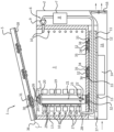
- the figure shows a diagrammatic sectional view of a measuring system 1 according to the invention.
- the measuring system 1 comprises a housing 2 with an interior space 3 and one product container 4, as well as a lid 5.
- a cooling device is denoted by reference numeral 6 which comprises a storage container 7 for refrigerant 8, a pump 9, a pipe system 10, a cold buffer 11 with a phase change material 12, a Peltier cooler 13, a heatsink 15, a ventilation space 15 and a fan 16. Insulating material 17 and 18, respectively, is provided in the housing 2 and the lid 5, respectively.
- the product container 4 comprises a cup 19 and a container lid 20 with a probe 21 with a thermometer 22.
- a magnetic body is denoted by reference numeral 23.
- a sensor sphere 24 surrounds optical sensors 25 and is provided with contacts 26.
- Electromagnetic coils 27 surround a carrier 28 with Hall sensors 29.
- the lid 5 is provided with countercontacts 30 to electronics 31.
- Cameras 32 are connected to respective camera control units 33.
- a plurality of LEDs 34 are arranged around the camera and above them a protective glass 35 is placed.
- reference numeral 36 denotes a connection to the outside and reference numeral 37 denotes a control unit for the system 1.
- the illustrated system 1 comprises a housing 2 and lid 5 of, for example, metal or plastic, which surround an interior space 3 which is insulated with insulating material 17 and 18.
- a plurality of product containers 4 may be placed in the interior space 3, in the illustrated example three, of which only one is shown for the sake of clarity.
- the interior space 3 may be brought to a desired temperature by the control unit 35.
- the cooling system 6 is additionally provided with a heating device (not shown here), such as electrical heating wires or the like. These can bring the interior space to a higher desired temperature in a manner which is known per se.
- the control unit 35 may actuate the cooling part, that is to say the cooling system 6, to bring the interior space 3 to a desired lower temperature.
- the cooling system 6 comprises a storage container 7 with a refrigerant 8, such as glycol, which serves to transfer heat.
- a pump 9 pumps the refrigerant 8 through a, for example spiral-shaped, pipe system 10 around the interior space 3.
- the refrigerant 8 may dissipate its heat to the phase change material (PCM) 12 in the cold buffer 11.
- PCM 12 may simply be water/ice, wherein the heat absorbed from the refrigerant 8 makes the ice melt to form water, but advantageously, the PCM may also be a different material.
- a particular drawback of water is the fact that it expands when it solidifies, and that the melting point is at 0°C, or below if additives were added.
- numerous other PCMs are available which do not have these drawbacks and which have phase transitions which are, for example, at a temperature between 5 and 40°C.
- the interior space may be heated first to a pasteurisation temperature, such as 72°C, or also a sterilisation temperature, such as around 130°C.
- a pasteurisation temperature such as 72°C
- a sterilisation temperature such as around 130°C.
- Important other temperatures are use temperatures to which foodstuffs may be exposed, such as heating up to 30 to 40°C on a loading platform in the sun or on the table of a consumer, and then back to a cooling temperature of 4 - 6°C.
- thermometer 22 measures the temperature of the foodstuff in the product container 4, with which signal the control unit 35 can actuate the cooling system 6 and or the heating system.
- a refrigerant is thus pumped around in the cooling circuit with pipe system 10 by means of the pump 9.
- the PCM 12 in the cold buffer 11 is itself cooled by means of any known cooling device, such as a heat pump or a Joule-Thomson cooling system.
- any known cooling device such as a heat pump or a Joule-Thomson cooling system.
- it is advantageous to choose a compact cooling system because space is limited or may be expensive, in particular in a laboratory.
- moving parts are not always desired.
- a Peltier cooling system 13 is advantageous, as it is compact and does not contain moving parts itself.
- a fan 16 is provided which guides air past a heatsink 14 via a ventilation space 15, so that the heat can be dissipated from the system 1 in an efficient manner.
- cameras 32 are arranged which have an upwardly directed image field and thus form an image of the underside of their respective product container 4.
- the latter has to be made either from a transparent material, such as glass or polycarbonate, or also be flexible, such as PE film, or have a transparent window.
- the associated control and/or processing electronics may be provided under the insulation 17, so that it is protected against the changing and sometimes extreme temperatures.
- Using the camera it is possible to produce an image of the foodstuff in the product container 4. In particular, it is thus possible to observe changes in the colour and/or deposits, which may be important to monitor and measure the quality overall, or certain product properties in particular, as a function of temperature and/or time.
- a light source is provided to support the operation of the camera 32, in this case in the form of a plurality of LEDs 34.
- the LEDs may emit light of the same or different colours and, as they are provided around the camera, they can use the same electronics platform.
- the LEDs 34 can emit light into the product in the product container 19 via the protective glass 35, which is made, for example, from borosilicate glass, fused glass or another translucent and preferably chemical-, temperature- and scratch-resistant material. Emitted light which has subsequently been reflected by the product can be detected by the camera 32 and then be analysed by the control unit 37, or can be transmitted externally for further processing via the connection 36. It is also still possible to provide still other sensors (not shown here) in addition to the camera 32, such as InGaAs or Si sensors, which offer better sensitivity in, for example, the (N)IR range than most cameras 32.
- Another possibility is to provide a light source in the lid 20 of the product container 4.
- light conductors such as optical fibers, may be provided in the sensor sphere 24, where the emitted light may be injected, and the probe 21 may be inserted. Reflected light or diffused light can then also be collected by one or more light conductors in the probe and sent to the sensor sphere 24, where sensors 25 can measure the light in order to thus obtain additional information about colour and, for example, transparency. A portion of the light will be reflected and a portion will be transmitted, so that the respective coefficients for the foodstuff can be determined by the control unit therefrom.
- a viscosity-measuring device is also provided to measure the viscosity and changes therein of the foodstuff in the respective product container 4.
- the viscosity-measuring device comprises a series of coils 27 which are arranged around the product container 4, as well as a series of Hall sensors 29 on a carrier 28 and a magnetic body 23 around the probe 22. This is in itself similar to the known "falling ball" measurement.
- the control unit 35 energises the individual coils 27 in a suitable pattern.
- the magnetic body 23 is attracted by respective magnetic fields of the individual coils 27 and possibly even, after polarity reversal, repelled, as a result of which it moves and moves, for example, upwards.
- An important additional advantage of the described magnetic system is the fact that this can also be used to mix the foodstuff in the product container 4, in particular by repeatedly and/or quickly moving the magnetic body up and down. This mixing makes it possible, for example, to cancel sedimentation as much as possible, and to then measure the product properties. Consumers often do something similar with the respective product, such as "shake well before use ".
- the sensor device(s) is/are built into the respective lid of the product container.
- the sensor device(s) is/are built into the respective lid of the product container.
- the sensor device(s) is/are replaceably fittable, such as in the lid of the product container.
- An important advantage thereof is that it is very simple to fit the required sensor device(s) for each experiment and for each product in the system, and to automatically perform the associated measurements. This provides a high degree of flexibility.
- one product container 4 is provided and illustrated in the interior space 3.
- associated coils 27, a carrier 28 with Hall sensors 29, a camera 32, etc. only some of which are shown here for the sake of clarity, will in each case be provided for each available location for a product container in the interior space 3, of which three are shown here.
- different numbers of available locations may be provided, such as two, four, five, etc.
- one or more product containers 4 are filled with a foodstuff to be measured, for example with different recipes or also the same, for redundant measurements.
- the lid 5 of the system 1 is closed.
- the insulation 17 and 18 around the interior space 3 with the product container(s) 4 seals. This also protects the electronics 31 against temperature variations.
- the sensors 25 in the sensor sphere 24 it is also possible to provide the sensors 25 in the sensor sphere 24 with insulation.
- the countercontacts 30 in the lid make contact with the contacts 26 on the lid 20 of the product container, so that the electronics 31 can ensure control of the optional sensors 25, the thermometer 22, etc.
- a desired time-temperature profile is input into the control unit 35 by a user, such as via the connection 34, which may obviously also be designed as a wireless connection (Bluetooth ® or the like) or a USB connection, SD card or even via the lid 5 provided on the product container 4, etc.
- the control unit 35 will subsequently actuate the heating and/or the cooling system 6, under the control of the temperature measured by the thermometer 22, in order to set the desired profile.
- the control unit 35 will cause the one or more sensors 22, 25, 29, 32 to perform one or more measurements.
- the measured data which are thus collected may be stored by the control unit for future use. They may also be sent to an external data storage or data processing facility via the connection 34.
- control unit 35 may also be processed by the control unit 35, for example in order to monitor if one or more product parameters fall outside a desired range. In this case, examples thereof may be checking the colour of the product or the transparency/deposits by means of the camera 32 or the viscosity. Should the value be outside a desired range, the control unit can emit an alarm signal, again for example via the connection 34. If desired, the remaining part of the time-temperature profile may be cancelled. Alternatively, it is possible to determine how long it took before the value moved outside the desired range for the foodstuff in the respective product container 4. This makes it possible, for example, to determine a shelf life.
Landscapes
- Health & Medical Sciences (AREA)
- Chemical & Material Sciences (AREA)
- Life Sciences & Earth Sciences (AREA)
- Physics & Mathematics (AREA)
- Immunology (AREA)
- Biochemistry (AREA)
- Pathology (AREA)
- Analytical Chemistry (AREA)
- General Physics & Mathematics (AREA)
- General Health & Medical Sciences (AREA)
- Engineering & Computer Science (AREA)
- Food Science & Technology (AREA)
- Medicinal Chemistry (AREA)
- Chemical Kinetics & Catalysis (AREA)
- Optics & Photonics (AREA)
- Nuclear Medicine, Radiotherapy & Molecular Imaging (AREA)
- Spectroscopy & Molecular Physics (AREA)
- Molecular Biology (AREA)
- Investigating Or Analysing Materials By Optical Means (AREA)
Claims (11)
- Messsystem (1) zum automatischen Bestimmen und/oder Überwachen der Qualität eines flüssigen oder viskosen Lebensmittels, und umfassend- mindestens einen Produktbehälter (4) zum Aufnehmen eines derartigen Lebensmittels darin,- ein Gehäuse (2) mit einem Innenraum (3) zum Aufnehmen des Produktbehälters,- eine Heiz- und Kühlvorrichtung (6) zum Heizen und Kühlen des Innenraums, und- eine Steuereinheit (37) zum Steuern des Messsystems, wobei der Produktbehälter mit Folgendem versehen ist- einem Deckel (20) mit einer Sonde (21), die in den Produktbehälter hineinragt und mit einem Thermometer (22) versehen ist, und- einer Wand (19), von der zumindest ein Teil optisch transparent ist,wobei das Gehäuse ferner Folgendes umfasst:- eine Lichtquelle (34) zum Emittieren von Licht durch den Teil der Wand in den Produktbehälter, und- einen optischen Sensor (25, 32) zum Registrieren des von dem Produktbehälter ausgehenden Lichts,ferner umfassend eine erste Messvorrichtung (23, 27, 29) für rheologische Eigenschaften des Lebensmittels, insbesondere einen Viskositätsmesser,wobei die Steuereinheit mit dem Thermometer, der Heiz- und Kühlvorrichtung, der Lichtquelle, dem optischen Sensor und der ersten Messvorrichtung wirkverbunden ist und zu Folgendem ausgelegt ist:- Einstellen eines vorbestimmten Zeit-Temperatur-Programms in dem Innenraum für eine Zeitdauer durch die Heiz- und Kühlvorrichtung, und- Steuern mindestens einer der ersten Messvorrichtung und der Lichtquelle und des optischen Sensors zum automatisch wiederholten Durchführen einer zugehörigen Messung an dem Lebensmittel in dem Produktbehälter während der Zeitdauer zum Bestimmen eines Messwerts dadurch in Bezug auf das Lebensmittel und zum Speichern und/oder Exportieren und/oder Verarbeiten der Messwerte.
- Messsystem nach Anspruch 1, wobei der Produktbehälter eine maßbeständige Wand (19) mit einem transparenten Teil oder eine flexible Wand aus transparentem Kunststoff aufweist.
- Messsystem nach einem der vorhergehenden Ansprüche, wobei der optische Sensor eine Kamera (32) umfasst.
- Messsystem nach einem der vorhergehenden Ansprüche, wobei die Lichtquelle eine oder mehrere LEDs (34) umfasst.
- Messsystem nach Anspruch 4, wobei die Lichtquelle (34) um den optischen Sensor (32) herum angeordnet ist.
- Messsystem nach Anspruch 4, wobei die Lichtquelle auf dem Behälter über der Sonde angeordnet ist und mindestens einen Lichtleiter, wie beispielsweise eine optische Faser, neben der oder durch die Sonde hindurch umfasst.
- Messsystem nach einem der vorhergehenden Ansprüche, wobei die erste Messvorrichtung Folgendes umfasst:- einen magnetischen Körper (23),- einen steuerbaren elektromagnetischen Antrieb (27) für den Körper, und- ein Detektionssystem zum Detektieren einer Verschiebung des Körpers, das eine Mehrzahl von Näherungssensoren, insbesondere Hallsensoren (29), umfasst,wobei im Gebrauch sich der Körper in dem Behälter befindet und aufgrund des Antriebs in dem Behälter verschiebbar ist.
- Messsystem nach Anspruch 7, wobei der Körper (23) um die Sonde herum angeordnet ist.
- Messsystem nach Anspruch 7 oder 8, wobei der Antrieb eine Mehrzahl von einzeln erregbaren Spulen (27) umfasst, die um den Behälter gewickelt und in einen Stapel gestapelt sind,
wobei die Steuereinheit dazu ausgelegt ist, die Spulen derart einzeln zu erregen, dass der Körper in dem Behälter, insbesondere in einem vorbestimmten Muster, verschoben wird. - Messsystem nach einem der vorhergehenden Ansprüche, umfassend mindestens einen zusätzlichen Sensor zum Bestimmen eines zusätzlichen Messwerts in Bezug auf das Lebensmittel in dem Produktbehälter.
- Messsystem nach einem der vorhergehenden Ansprüche, wobei die Steuereinheit zum jeweiligen Verarbeiten mindestens eines während des Zeit-Temperatur-Programms bestimmten Messwerts und/oder optionalen zusätzlichen Messwerts durch Folgendes ausgelegt ist- Erzeugen eines Alarmsignals, wenn und/oder- Registrieren einer vergangenen Zeitdauer bis der bestimmte Messwert und/oder optional der zusätzliche Messwert ein vorbestimmtes Kriterium, insbesondere ein Verfallskriterium, erfüllt.
Applications Claiming Priority (2)
| Application Number | Priority Date | Filing Date | Title |
|---|---|---|---|
| NL2023921A NL2023921B1 (nl) | 2019-10-01 | 2019-10-01 | Meetsysteem voor levensmiddelen |
| PCT/NL2020/050594 WO2021066644A1 (en) | 2019-10-01 | 2020-09-25 | Measuring system for foodstuffs |
Publications (3)
| Publication Number | Publication Date |
|---|---|
| EP4038382A1 EP4038382A1 (de) | 2022-08-10 |
| EP4038382B1 true EP4038382B1 (de) | 2025-02-26 |
| EP4038382C0 EP4038382C0 (de) | 2025-02-26 |
Family
ID=68425236
Family Applications (1)
| Application Number | Title | Priority Date | Filing Date |
|---|---|---|---|
| EP20785607.1A Active EP4038382B1 (de) | 2019-10-01 | 2020-09-25 | Messsystem für lebensmittel |
Country Status (5)
| Country | Link |
|---|---|
| US (1) | US12235199B2 (de) |
| EP (1) | EP4038382B1 (de) |
| CN (1) | CN114585900B (de) |
| NL (1) | NL2023921B1 (de) |
| WO (1) | WO2021066644A1 (de) |
Family Cites Families (12)
| Publication number | Priority date | Publication date | Assignee | Title |
|---|---|---|---|---|
| DE4206107A1 (de) * | 1992-02-27 | 1993-09-02 | Funke Dr N Gerber Gmbh | Verfahren und vorrichtung zur bestimmung der trockenmasse von fluessigkeiten, insbesondere milch |
| JP3711303B2 (ja) * | 1996-11-08 | 2005-11-02 | 出光興産株式会社 | 液体の粘度測定装置および測定方法 |
| NZ521285A (en) * | 2002-09-10 | 2005-01-28 | Otago Osmometers Ltd | Recrystallisation measurement device and method |
| US7500385B2 (en) * | 2005-11-23 | 2009-03-10 | Waters Investments Limited | System for in-situ optical measurement and sample heating during rheometric measurements |
| US7614285B2 (en) * | 2007-03-27 | 2009-11-10 | Cambridge Viscosity, Inc. | Dynamic reciprocating-bob rheometry |
| KR101125602B1 (ko) * | 2010-01-05 | 2012-03-27 | 한국과학기술연구원 | 오일점도 프로브와 이를 구비하는 오일점도 모니터링 장치 및 방법 |
| US20140224000A1 (en) * | 2011-07-27 | 2014-08-14 | Schlumberger Technology Corporation | Estimating Oil Viscosity |
| RU2504757C2 (ru) * | 2012-04-28 | 2014-01-20 | Федеральное государственное бюджетное учреждение науки Институт радиотехники и электроники им. В.А. Котельникова Российской академии наук | Способ исследования теплофизических свойств жидкостей и устройство для его осуществления |
| EP3036527B1 (de) * | 2013-07-02 | 2018-04-18 | Universitat Autònoma De Barcelona | Verfahren und system zur bestimmung von gelfestigkeitswerten anhand optischer inline-messungen |
| EP3211417A1 (de) * | 2016-02-23 | 2017-08-30 | C.C. Jensen A/S | System und sensoreinheit zur überwachung und auswertung von des zustands einer flüssigkeit |
| AT518797A1 (de) * | 2016-06-22 | 2018-01-15 | Anton Paar Gmbh | Verfahren und Vorrichtung zur Prüfung des Befüllungszustandes |
| DE102016118617B4 (de) * | 2016-09-30 | 2019-02-28 | Carl Zeiss Industrielle Messtechnik Gmbh | Messsystem |
-
2019
- 2019-10-01 NL NL2023921A patent/NL2023921B1/nl not_active IP Right Cessation
-
2020
- 2020-09-25 CN CN202080068296.4A patent/CN114585900B/zh active Active
- 2020-09-25 US US17/765,653 patent/US12235199B2/en active Active
- 2020-09-25 EP EP20785607.1A patent/EP4038382B1/de active Active
- 2020-09-25 WO PCT/NL2020/050594 patent/WO2021066644A1/en not_active Ceased
Also Published As
| Publication number | Publication date |
|---|---|
| WO2021066644A1 (en) | 2021-04-08 |
| US20220357259A1 (en) | 2022-11-10 |
| US12235199B2 (en) | 2025-02-25 |
| CN114585900B (zh) | 2025-08-15 |
| CN114585900A (zh) | 2022-06-03 |
| EP4038382C0 (de) | 2025-02-26 |
| EP4038382A1 (de) | 2022-08-10 |
| NL2023921B1 (nl) | 2021-06-01 |
Similar Documents
| Publication | Publication Date | Title |
|---|---|---|
| EP4038327B1 (de) | Messsystem für lebensmittel | |
| CN109892008A (zh) | 无线感测封闭环境的性质及其装置 | |
| US6664113B2 (en) | Fluorescence detection method capable of making measurement under external light | |
| EP2400282B1 (de) | Verfahren und Steuerung von Verfahrensparametern | |
| EP4038362B1 (de) | Messsystem für lebensmittel | |
| US11047747B2 (en) | Light weight flexible temperature sensor kit | |
| JP2020531867A (ja) | 包装検査方法 | |
| EP4038382B1 (de) | Messsystem für lebensmittel | |
| US20160313188A1 (en) | Temperature monitoring of subject bodies using wireless energy transfer | |
| JP2007309840A (ja) | 光源装置及び分析装置 | |
| US12241793B2 (en) | Electronically readable colorimetric sensor | |
| WO2021066647A1 (en) | Measuring system for foodstuffs | |
| KR20190063298A (ko) | 휴대형 냉온장 용기 | |
| Mospan et al. | THE SYSTEM OF THERMOSTABILIZATION BIOMATERIALS IN MICRO CUVETTES | |
| TH20482A (th) | Cloud point and pour point analyzer | |
| JP2007285760A (ja) | 分析装置 |
Legal Events
| Date | Code | Title | Description |
|---|---|---|---|
| STAA | Information on the status of an ep patent application or granted ep patent |
Free format text: STATUS: UNKNOWN |
|
| STAA | Information on the status of an ep patent application or granted ep patent |
Free format text: STATUS: THE INTERNATIONAL PUBLICATION HAS BEEN MADE |
|
| PUAI | Public reference made under article 153(3) epc to a published international application that has entered the european phase |
Free format text: ORIGINAL CODE: 0009012 |
|
| STAA | Information on the status of an ep patent application or granted ep patent |
Free format text: STATUS: REQUEST FOR EXAMINATION WAS MADE |
|
| 17P | Request for examination filed |
Effective date: 20220502 |
|
| AK | Designated contracting states |
Kind code of ref document: A1 Designated state(s): AL AT BE BG CH CY CZ DE DK EE ES FI FR GB GR HR HU IE IS IT LI LT LU LV MC MK MT NL NO PL PT RO RS SE SI SK SM TR |
|
| DAV | Request for validation of the european patent (deleted) | ||
| DAX | Request for extension of the european patent (deleted) | ||
| GRAP | Despatch of communication of intention to grant a patent |
Free format text: ORIGINAL CODE: EPIDOSNIGR1 |
|
| STAA | Information on the status of an ep patent application or granted ep patent |
Free format text: STATUS: GRANT OF PATENT IS INTENDED |
|
| RIC1 | Information provided on ipc code assigned before grant |
Ipc: G01N 21/85 20060101ALN20240501BHEP Ipc: G01N 21/64 20060101ALN20240501BHEP Ipc: G01N 21/49 20060101ALN20240501BHEP Ipc: G01N 21/25 20060101ALN20240501BHEP Ipc: G01N 11/12 20060101ALN20240501BHEP Ipc: G01N 21/03 20060101ALI20240501BHEP Ipc: G01N 11/10 20060101ALI20240501BHEP Ipc: G01N 33/04 20060101AFI20240501BHEP |
|
| INTG | Intention to grant announced |
Effective date: 20240516 |
|
| GRAJ | Information related to disapproval of communication of intention to grant by the applicant or resumption of examination proceedings by the epo deleted |
Free format text: ORIGINAL CODE: EPIDOSDIGR1 |
|
| STAA | Information on the status of an ep patent application or granted ep patent |
Free format text: STATUS: REQUEST FOR EXAMINATION WAS MADE |
|
| GRAP | Despatch of communication of intention to grant a patent |
Free format text: ORIGINAL CODE: EPIDOSNIGR1 |
|
| STAA | Information on the status of an ep patent application or granted ep patent |
Free format text: STATUS: GRANT OF PATENT IS INTENDED |
|
| INTC | Intention to grant announced (deleted) | ||
| RIC1 | Information provided on ipc code assigned before grant |
Ipc: G01N 21/85 20060101ALN20240909BHEP Ipc: G01N 21/64 20060101ALN20240909BHEP Ipc: G01N 21/49 20060101ALN20240909BHEP Ipc: G01N 21/25 20060101ALN20240909BHEP Ipc: G01N 11/12 20060101ALN20240909BHEP Ipc: G01N 21/03 20060101ALI20240909BHEP Ipc: G01N 11/10 20060101ALI20240909BHEP Ipc: G01N 33/04 20060101AFI20240909BHEP |
|
| INTG | Intention to grant announced |
Effective date: 20240918 |
|
| GRAS | Grant fee paid |
Free format text: ORIGINAL CODE: EPIDOSNIGR3 |
|
| GRAA | (expected) grant |
Free format text: ORIGINAL CODE: 0009210 |
|
| STAA | Information on the status of an ep patent application or granted ep patent |
Free format text: STATUS: THE PATENT HAS BEEN GRANTED |
|
| AK | Designated contracting states |
Kind code of ref document: B1 Designated state(s): AL AT BE BG CH CY CZ DE DK EE ES FI FR GB GR HR HU IE IS IT LI LT LU LV MC MK MT NL NO PL PT RO RS SE SI SK SM TR |
|
| REG | Reference to a national code |
Ref country code: GB Ref legal event code: FG4D |
|
| REG | Reference to a national code |
Ref country code: CH Ref legal event code: EP |
|
| REG | Reference to a national code |
Ref country code: DE Ref legal event code: R096 Ref document number: 602020046827 Country of ref document: DE |
|
| REG | Reference to a national code |
Ref country code: IE Ref legal event code: FG4D |
|
| U01 | Request for unitary effect filed |
Effective date: 20250307 |
|
| U07 | Unitary effect registered |
Designated state(s): AT BE BG DE DK EE FI FR IT LT LU LV MT NL PT RO SE SI Effective date: 20250314 |
|
| PG25 | Lapsed in a contracting state [announced via postgrant information from national office to epo] |
Ref country code: RS Free format text: LAPSE BECAUSE OF FAILURE TO SUBMIT A TRANSLATION OF THE DESCRIPTION OR TO PAY THE FEE WITHIN THE PRESCRIBED TIME-LIMIT Effective date: 20250526 |
|
| PG25 | Lapsed in a contracting state [announced via postgrant information from national office to epo] |
Ref country code: PL Free format text: LAPSE BECAUSE OF FAILURE TO SUBMIT A TRANSLATION OF THE DESCRIPTION OR TO PAY THE FEE WITHIN THE PRESCRIBED TIME-LIMIT Effective date: 20250226 |
|
| PG25 | Lapsed in a contracting state [announced via postgrant information from national office to epo] |
Ref country code: ES Free format text: LAPSE BECAUSE OF FAILURE TO SUBMIT A TRANSLATION OF THE DESCRIPTION OR TO PAY THE FEE WITHIN THE PRESCRIBED TIME-LIMIT Effective date: 20250226 |
|
| PG25 | Lapsed in a contracting state [announced via postgrant information from national office to epo] |
Ref country code: IS Free format text: LAPSE BECAUSE OF FAILURE TO SUBMIT A TRANSLATION OF THE DESCRIPTION OR TO PAY THE FEE WITHIN THE PRESCRIBED TIME-LIMIT Effective date: 20250626 Ref country code: NO Free format text: LAPSE BECAUSE OF FAILURE TO SUBMIT A TRANSLATION OF THE DESCRIPTION OR TO PAY THE FEE WITHIN THE PRESCRIBED TIME-LIMIT Effective date: 20250526 |
|
| PG25 | Lapsed in a contracting state [announced via postgrant information from national office to epo] |
Ref country code: HR Free format text: LAPSE BECAUSE OF FAILURE TO SUBMIT A TRANSLATION OF THE DESCRIPTION OR TO PAY THE FEE WITHIN THE PRESCRIBED TIME-LIMIT Effective date: 20250226 |
|
| PG25 | Lapsed in a contracting state [announced via postgrant information from national office to epo] |
Ref country code: GR Free format text: LAPSE BECAUSE OF FAILURE TO SUBMIT A TRANSLATION OF THE DESCRIPTION OR TO PAY THE FEE WITHIN THE PRESCRIBED TIME-LIMIT Effective date: 20250527 |
|
| PG25 | Lapsed in a contracting state [announced via postgrant information from national office to epo] |
Ref country code: SM Free format text: LAPSE BECAUSE OF FAILURE TO SUBMIT A TRANSLATION OF THE DESCRIPTION OR TO PAY THE FEE WITHIN THE PRESCRIBED TIME-LIMIT Effective date: 20250226 |
|
| PGFP | Annual fee paid to national office [announced via postgrant information from national office to epo] |
Ref country code: GB Payment date: 20250929 Year of fee payment: 6 |
|
| PG25 | Lapsed in a contracting state [announced via postgrant information from national office to epo] |
Ref country code: CZ Free format text: LAPSE BECAUSE OF FAILURE TO SUBMIT A TRANSLATION OF THE DESCRIPTION OR TO PAY THE FEE WITHIN THE PRESCRIBED TIME-LIMIT Effective date: 20250226 |
|
| PG25 | Lapsed in a contracting state [announced via postgrant information from national office to epo] |
Ref country code: SK Free format text: LAPSE BECAUSE OF FAILURE TO SUBMIT A TRANSLATION OF THE DESCRIPTION OR TO PAY THE FEE WITHIN THE PRESCRIBED TIME-LIMIT Effective date: 20250226 |
|
| U20 | Renewal fee for the european patent with unitary effect paid |
Year of fee payment: 6 Effective date: 20250930 |
|
| PLBE | No opposition filed within time limit |
Free format text: ORIGINAL CODE: 0009261 |
|
| STAA | Information on the status of an ep patent application or granted ep patent |
Free format text: STATUS: NO OPPOSITION FILED WITHIN TIME LIMIT |
|
| 26N | No opposition filed |
Effective date: 20251127 |