EP4038299B1 - Profilschelle mit verrastlasche - Google Patents
Profilschelle mit verrastlasche Download PDFInfo
- Publication number
- EP4038299B1 EP4038299B1 EP20789008.8A EP20789008A EP4038299B1 EP 4038299 B1 EP4038299 B1 EP 4038299B1 EP 20789008 A EP20789008 A EP 20789008A EP 4038299 B1 EP4038299 B1 EP 4038299B1
- Authority
- EP
- European Patent Office
- Prior art keywords
- latching
- clamp
- flange
- profile clamp
- designed
- Prior art date
- Legal status (The legal status is an assumption and is not a legal conclusion. Google has not performed a legal analysis and makes no representation as to the accuracy of the status listed.)
- Active
Links
Images


Classifications
-
- B—PERFORMING OPERATIONS; TRANSPORTING
- B25—HAND TOOLS; PORTABLE POWER-DRIVEN TOOLS; MANIPULATORS
- B25B—TOOLS OR BENCH DEVICES NOT OTHERWISE PROVIDED FOR, FOR FASTENING, CONNECTING, DISENGAGING, OR HOLDING
- B25B11/00—Work holders not covered by any preceding group in the subclass, e.g. magnetic work holders, vacuum work holders
-
- F—MECHANICAL ENGINEERING; LIGHTING; HEATING; WEAPONS; BLASTING
- F16—ENGINEERING ELEMENTS AND UNITS; GENERAL MEASURES FOR PRODUCING AND MAINTAINING EFFECTIVE FUNCTIONING OF MACHINES OR INSTALLATIONS; THERMAL INSULATION IN GENERAL
- F16L—PIPES; JOINTS OR FITTINGS FOR PIPES; SUPPORTS FOR PIPES, CABLES OR PROTECTIVE TUBING; MEANS FOR THERMAL INSULATION IN GENERAL
- F16L23/00—Flanged joints
- F16L23/04—Flanged joints the flanges being connected by members tensioned in the radial plane
- F16L23/08—Flanged joints the flanges being connected by members tensioned in the radial plane connection by tangentially arranged pin and nut
-
- F—MECHANICAL ENGINEERING; LIGHTING; HEATING; WEAPONS; BLASTING
- F01—MACHINES OR ENGINES IN GENERAL; ENGINE PLANTS IN GENERAL; STEAM ENGINES
- F01N—GAS-FLOW SILENCERS OR EXHAUST APPARATUS FOR MACHINES OR ENGINES IN GENERAL; GAS-FLOW SILENCERS OR EXHAUST APPARATUS FOR INTERNAL-COMBUSTION ENGINES
- F01N13/00—Exhaust or silencing apparatus characterised by constructional features
- F01N13/18—Construction facilitating manufacture, assembly, or disassembly
-
- F—MECHANICAL ENGINEERING; LIGHTING; HEATING; WEAPONS; BLASTING
- F01—MACHINES OR ENGINES IN GENERAL; ENGINE PLANTS IN GENERAL; STEAM ENGINES
- F01N—GAS-FLOW SILENCERS OR EXHAUST APPARATUS FOR MACHINES OR ENGINES IN GENERAL; GAS-FLOW SILENCERS OR EXHAUST APPARATUS FOR INTERNAL-COMBUSTION ENGINES
- F01N13/00—Exhaust or silencing apparatus characterised by constructional features
- F01N13/18—Construction facilitating manufacture, assembly, or disassembly
- F01N13/1805—Fixing exhaust manifolds, exhaust pipes or pipe sections to each other, to engine or to vehicle body
-
- F—MECHANICAL ENGINEERING; LIGHTING; HEATING; WEAPONS; BLASTING
- F01—MACHINES OR ENGINES IN GENERAL; ENGINE PLANTS IN GENERAL; STEAM ENGINES
- F01N—GAS-FLOW SILENCERS OR EXHAUST APPARATUS FOR MACHINES OR ENGINES IN GENERAL; GAS-FLOW SILENCERS OR EXHAUST APPARATUS FOR INTERNAL-COMBUSTION ENGINES
- F01N13/00—Exhaust or silencing apparatus characterised by constructional features
- F01N13/18—Construction facilitating manufacture, assembly, or disassembly
- F01N13/1838—Construction facilitating manufacture, assembly, or disassembly characterised by the type of connection between parts of exhaust or silencing apparatus, e.g. between housing and tubes, between tubes and baffles
- F01N13/1844—Mechanical joints
- F01N13/1855—Mechanical joints the connection being realised by using bolts, screws, rivets or the like
-
- F—MECHANICAL ENGINEERING; LIGHTING; HEATING; WEAPONS; BLASTING
- F01—MACHINES OR ENGINES IN GENERAL; ENGINE PLANTS IN GENERAL; STEAM ENGINES
- F01N—GAS-FLOW SILENCERS OR EXHAUST APPARATUS FOR MACHINES OR ENGINES IN GENERAL; GAS-FLOW SILENCERS OR EXHAUST APPARATUS FOR INTERNAL-COMBUSTION ENGINES
- F01N13/00—Exhaust or silencing apparatus characterised by constructional features
- F01N13/18—Construction facilitating manufacture, assembly, or disassembly
- F01N13/1872—Construction facilitating manufacture, assembly, or disassembly the assembly using stamp-formed parts or otherwise deformed sheet-metal
-
- F—MECHANICAL ENGINEERING; LIGHTING; HEATING; WEAPONS; BLASTING
- F01—MACHINES OR ENGINES IN GENERAL; ENGINE PLANTS IN GENERAL; STEAM ENGINES
- F01N—GAS-FLOW SILENCERS OR EXHAUST APPARATUS FOR MACHINES OR ENGINES IN GENERAL; GAS-FLOW SILENCERS OR EXHAUST APPARATUS FOR INTERNAL-COMBUSTION ENGINES
- F01N2450/00—Methods or apparatus for fitting, inserting or repairing different elements
- F01N2450/24—Methods or apparatus for fitting, inserting or repairing different elements by bolts, screws, rivets or the like
-
- F—MECHANICAL ENGINEERING; LIGHTING; HEATING; WEAPONS; BLASTING
- F16—ENGINEERING ELEMENTS AND UNITS; GENERAL MEASURES FOR PRODUCING AND MAINTAINING EFFECTIVE FUNCTIONING OF MACHINES OR INSTALLATIONS; THERMAL INSULATION IN GENERAL
- F16L—PIPES; JOINTS OR FITTINGS FOR PIPES; SUPPORTS FOR PIPES, CABLES OR PROTECTIVE TUBING; MEANS FOR THERMAL INSULATION IN GENERAL
- F16L2201/00—Special arrangements for pipe couplings
- F16L2201/10—Indicators for correct coupling
Definitions
- the invention relates to a profile clamp with a locking tab according to the preamble of claim 1.
- a clamp such as a profile clamp
- the flanges are positioned relative to each other and the profile clamp with a tensionable clamp band, usually made up of two or more parts, is placed on the flanges.
- the connection is fixed by tensioning the profile clamp by applying axial and radial holding forces to the flanges.
- a clamp band of the profile clamp usually has a U-shaped or V-shaped cross-section that comes into surface contact with the flanges.
- a ring element with an annular sealing area is often inserted between the flanges, which comes into axial surface contact with both flanges, whereby the sealing effect is achieved by clamping the flanges.
- Profile clamps with a clamp band and an annular ring element with a ring body are known, which are used to connect two pipe ends or flanges.
- the clamp band usually comprises two clamping heads, which are or can be connected to one another via a clamping element.
- the ring element is precisely aligned with the flanges. If the ring element is separate and not attached to the clamp or a flange, a user must handle the clamp, the ring element and the pipes to be connected at the same time, making installation of the clamp more difficult. Before the pipe ends are connected, the pipe ends can be pre-positioned, which is usually done manually and is cumbersome. For this purpose, various locking elements can be arranged on the ring element to clamp the flange. Pre-positioning means that at least one, preferably both flanges clamp with the ring element, but the clamp band is not yet tightened.
- Such a profile clamp is, for example, from the EP 1 451 498 A1 and is used to connect two pipe ends.
- the clamp disclosed therein has a clamp band and an annular ring element which is arranged within the clamp band.
- the clamp has two clamping heads which are connected to one another by means of a screw as a clamping element.
- the ring element comprises fastening clamps which protrude in the axial direction of the clamp for fastening the ring element to the clamp.
- the fastening clamps are bent in such a way that their ends opposite the ring element rest on or against an inner surface or outer peripheral surface of the clamp. In other words, the ends of the fastening clamps interact with the clamp band.
- this interaction is disadvantageous and undesirable, as explained below.
- Some fastening clamps each have a tongue which engages behind the pipe end to clamp a pipe end. The pipe end is then irreversibly clamped between the tongue and a profile projection extending in the opposite direction in the ring element.
- the clamp band disclosed therein has a large number of relatively small tongues for clamping along its circumference.
- the large number of tongues means that the user carrying out the assembly cannot clearly determine whether there is a clamp between the clamp band and the flange or not, as all tongues must be clamped to ensure a secure seal.
- the small number of tongues also means that it is not possible to determine with certainty whether individual tongues are clamped. The user carrying out the assembly must therefore carry out a follow-up check after pre-positioning, which is cumbersome, time-consuming and costly.
- the object of the present invention is therefore to propose a profile clamp of the type mentioned at the beginning, which is simplified in terms of manufacturing effort and allows an unambiguously carried out pre-positioning to be recognized in a simple manner.
- a profile clamp with a clamp band and an annular ring element with a ring body wherein the clamp band has two clamping heads which are connected to one another via a clamping element, wherein the ring element comprises at least one first locking tab which is arranged to protrude from the ring body in the axial direction of the profile clamp and at least partially protrude from the clamp band, wherein the first locking tab has a first locking section and a free-swinging section running opposite thereto, wherein the first locking section is designed to exert a force acting in the direction of the transverse center plane of the profile clamp on a flange of a pipe end, and the first locking section has a first contact edge which is designed to produce a point contact or line contact with the flange of the pipe end.
- the first locking tab allows one pipe end to be pre-positioned on the ring element during assembly or when connecting the two pipe ends before the clamp band is finally tightened, which means that the pipe end no longer needs to be held separately.
- the pipe end simply snaps into place by inserting it into the ring element.
- the locking tab partially protrudes from the clamp band in such a way that the user can clearly see that it has snapped into place.
- the point or line contact ensures sufficient hold in the axial and radial directions while keeping the contact surface as small as possible.
- the two pipe ends to be connected can, for example, be designed as a pair of a funnel end and a biconical end. It is conceivable that the biconical end of the pipe interacts with the first locking tab.
- the ring element can have at least one holding element for support within the clamp band.
- the pipe ends can also be connected using a corresponding bottle.
- the first locking section and the free-swinging section are aligned with each other.
- there is no step or offset between these elements which allows a force flow unhindered and without deflection or vortex formation linearly from the first locking section to the free-swinging section.
- a deformation or change in position of the locking section therefore immediately leads to a deformation or change in position of the free-swinging section, which is clearly recognizable by the user. This makes it very easy for him to determine whether the device is jammed.
- the first locking section is designed as a section cut out of the first locking tab, in particular as a punched section. This makes it possible to create a monolithic first locking tab that can be produced inexpensively and can also be designed monolithically with the ring element.
- the first locking section is designed in the manner of a barb.
- the first locking section can be designed to act on the flange of the pipe end in the manner of a barb.
- a barb-like locking leads to a secure connection and, for example, to a reversible connection if the first locking tab and/or the first locking section is sufficiently deformable.
- the first contact edge is designed to transition into a radius on one side or both sides. This can prevent the flange or pipe end from being scratched or damaged by the first locking section when the flange is rotated about a longitudinal center axis.
- the first locking tab is designed such that the point contact or the line contact is the only contact between the first locking tab and the flange of the pipe end.
- the free-swinging section protrudes radially outwards at least in sections.
- the free-swinging section can therefore serve as a guide element in order to center the pipe end in the direction of the ring element when inserting the pipe end. It can be advantageous for the free-swinging section to be arranged outside the clamp band in order to enable the pipe end to be centered as early as possible. In addition, Locking due to deformation or change in position of the free-swinging section can be easily detected.
- the first locking tab is pre-tensioned radially outwards relative to the ring body, preferably pre-tensioned by spring force. This pre-tension leads to a secure and centering fit of the ring body in the clamp band and an advantageous centering effect through the free-swinging section.
- the first locking tab can rest against the clamp band when inserted into the clamp band.
- the clamp band can apply pressure to the first locking tab in the direction of the longitudinal center axis against the spring force.
- At least the first locking tab can be made of a material that can generate a suitable spring effect. Additionally or alternatively, at least the first locking tab can achieve a spring effect through its geometric design.
- the free-swinging section is arranged and/or designed in such a way that it can swing freely at least when the flange of the pipe end is locked to the first locking section and a perceptible locking sound can be generated and/or amplified.
- the flange of the pipe end can hit the first locking section when inserted and, depending on its design, deform, bend and/or tighten it. If at least one section of the flange passes the first locking section and locks with it, the first locking section can immediately return to its original starting position, which causes the locking section to swing suddenly. Because the free-swinging section can swing freely in space, a locking sound can be heard. It is advantageous that the clamp provides clear acoustic feedback when pre-positioned correctly and no further checking or readjustment is necessary.
- the profile clamp can comprise a second locking tab, which is arranged on the ring body and has a second locking section and a second contact edge, wherein the second locking tab is arranged and/or designed such that it can generate a perceptible locking noise at least when the flange of the pipe end is locked to the second locking section.
- the funnel-shaped end of the pipe interacts with the second locking tab and that it is pre-positioned thereon and held securely when the profile clamp is tightened.
- the first locking tab also interacts with the biconical end of the pipe, the at least one first locking tab protrudes from the ring body in the opposite direction along the longitudinal center axis than the at least second locking tab. In this way, both pipe ends can be easily locked to the ring body.
- first locking tab and/or the second locking tab is/are designed in such a way that the perceptible locking noise exceeds the human hearing threshold, preferably in the range of music perceptibility, more preferably in the range of speech perceptibility.
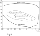
- Fig.5 shows the limits of music and speech perception mentioned above.
- the tabs can, for example, be designed in such a way that the generated engagement noise is adapted to a normal ambient noise level. For example, when assembling an exhaust pipe of a motor vehicle, the engagement noise must be able to be heard safely and clearly, especially by the person assembling it on the assembly line.
- a further development of the profile clamp according to the invention comprises at least three spaced first locking tabs on at least one side of the ring body with respect to the transverse center plane. It is conceivable that the ring body also comprises more than one second locking tab. With more than one first locking tab, the respective pipe end can be locked more securely, with three or four locking tabs enabling secure locking. More than four locking tabs do not significantly increase the locking security, but do increase the risk of non-locking, which would make an avoidable follow-up check necessary.
- the number of locking tabs is proportional to the diameter of the pipe ends or flanges to be connected. It is conceivable that a larger diameter requires more than four locking tabs. However, with a flow cross-section of the pipe ends in the clamp area of approximately 4 cm to 8 cm, three or four locking tabs are optimal.
- a ring element with a ring body for a profile clamp is also proposed, wherein the ring element comprises at least one first locking tab which is arranged in the axial direction of the ring element so as to protrude from the ring body, wherein the first locking tab has a first locking section and a free-swinging section running opposite thereto, wherein the first locking section is designed to exert a force acting in the direction of the transverse center plane of the ring element on a flange of a pipe end, and the first locking section has a first contact edge which is designed to produce a point contact or line contact with the flange of the pipe end.
- the ring element has the advantages and advantageous effects already described with regard to the profile clamp.
- the invention also includes a line connection arrangement with a line end on which a flange is formed, on which a profile clamp is arranged.
- FIG. 1 shows a clamp 10 according to the invention, which is designed as a profile clamp and can be pre-positioned on a flange of a pipe end. It is shown in the open position, i.e. not clamped, and in the pre-assembled state as it is delivered to the assembly site.
- the clamp 10 has a clamp band 14 with two clamping heads 16 and 18 or clamping jaws, which are connected to one another via a clamping element 20 and can be produced by bending the ends of the clamp band 14.
- it is also conceivable to form the clamping jaws for example, by bending the ends of the clamp band into loops, with clamping bolts inserted into the loops.
- the profile of the clamp band can also deviate relatively strongly from the shape shown with an essentially V-shaped cross-section with two flanks inclined radially inwards from a flat inner side.
- the clamp band 14 is shown as one piece, but in an embodiment not shown it can also be divided into two profile halves, which are connected to one another by means of a bridge element on a side opposite the clamping heads 16 and 18.
- the clamp band 14 is penetrated by a transverse center plane Q10, in which the largest diameter of the clamp band 14 lies.
- a longitudinal center axis L penetrating the profile clamp is orthogonal to the transverse center plane Q10.
- An exemplary ring-shaped ring element 24 with a ring body 26 is arranged within the clamp 10 and in Figure 2 shown in isolation.
- the ring element is penetrated centrally in its height relative to the longitudinal center axis L by a transverse center plane Q24, which is arranged parallel and spaced from the transverse center plane Q10.
- the ring element 24 comprises an outer edge 23, which faces away from the transverse center plane Q10, and an inner edge 25, which faces the transverse center plane Q10.
- the ring element 24 comprises four first locking tabs 50, which are arranged in the axial direction of the profile clamp 10 protruding from the ring body 26.
- the locking tabs 50 protrude at least in sections from the Clamp band 14 of the profile clamp 10 and are formed monolithically with the ring body 26 and arranged on its inner edge 25.
- Three second locking tabs 70 are also arranged monolithically and on the inner edge 25 on the ring body 26.
- the locking tabs 70 extend in the opposite direction with respect to the first locking tabs 50 along the longitudinal center axis L from the ring body 26.
- Each first locking tab 50 is S-shaped in section and comprises a base section 51, which on the one hand merges into the ring body 26.
- a holding section 53 adjoins this, on which two holding arms 55 are arranged symmetrically thereto in the circumferential direction.
- Each holding arm 55 has a curved shape that opens radially outwards in some areas and radially inwards in some areas, and forms a spring section.
- the distal end of each holding arm 55 is designed to run radially inwards. As a result, the distal end does not come into contact with an inner contour 36 of the clamp band 14 and does not interact with it. Rather, the central section of the holding arm 55, which is bent radially outwards, engages with the inner contour 36.
- the ring element 24 and the clamp band 14 are aligned symmetrically to one another and, if necessary, centrally with respect to the longitudinal central axis L.
- the holding arms 55 ensure a suitable position of the ring element 24 during transport and assembly of the clamp.
- the holding arms 55 extending in this way also lead to an advantageous rotation capability of the ring element 24 in the clamp band 14.
- the locking tabs 50 can elastically spring in with the holding arms 55 and thereby ensure their symmetrical relative position.
- the holding section 53 is followed by an intermediate section 57 and a free-swinging section 54, which also defines the distal end of the locking tab 50.
- each free-swinging section 54 projects radially outwards, which is particularly evident in the plan view according to Fig.3 can be seen.
- each free-swinging section 54 runs approximately in the direction of the intersection point between the transverse center plane Q10 and the longitudinal center axis L.
- the free-swinging sections 54 serve as guide elements in the manner of a funnel in order to center a pipe end to be inserted.
- Each locking tab 50 also comprises a locking section 52 which runs opposite to the free-swinging section 54.
- the free-swinging section 54 is punched out of the intermediate section 57 and is therefore also formed as a punched section monolithically with the locking tab 50. It can be seen that the first locking section 52 and the free-swinging section 54 of each locking tab 50 are aligned with one another or lie in one plane.
- the first locking section 52 is designed in the manner of a barb in order to exert a force acting in the direction of the transverse center plane Q10 of the profile clamp 10 on a flange of a pipe end. This allows the flange to be pre-positioned and held in this position.
- the first locking section 52 has a first contact edge 56 which is designed to establish a point contact or line contact with the flange of the pipe end.
- the point contact or line contact is the only contact between the first locking tabs 50 and the flange of the pipe end.
- the first contact edge 56 of each locking section 52 merges into a radius 58 on both sides.
- the first locking tab 50 is pre-tensioned radially outwardly relative to the ring body 26, so that the ring body 26 can rest on the inner contour 36 of the clamp band 14 and sits securely there.
- the free-swinging section 54 is arranged and designed such that it can swing freely when the flange of the pipe end is locked to the first locking section 52. This produces a perceptible locking noise and is amplified by the free vibration capability.
- Each second locking tab 70 comprises a second locking section 72, which can come into locking engagement with a flange of a pipe end via a second contact edge 76, and a wing section 74 on each side for creating a frictional connection with a flange of the pipe end.
- the wing sections protrude in the direction of the longitudinal center axis L and run parallel to it.
- guide lugs 38 are arranged on the ring body 26, which are tilted with respect to the longitudinal center axis L and project radially inwards and can center both tube ends with respect to the longitudinal center axis L.
- the ring element 24 can be manufactured on the basis of a sheet metal-like workpiece.
- the locking tabs 50 and 70 as well as the guide lugs 38 are formed in one piece with the ring element 24 and can be produced by punching and forming.
- the ring element 24 is now shown with an integrated sealing area 28, which forms a conically tapering extension of the ring element 24 that extends in the axial direction.
- the inclination of the sealing area 28 corresponds approximately to the inclination on an inner side of the flange at the pipe end, so that it can be brought into contact with the flange in a flat manner.
- Figure 5 shows the human hearing area in a diagram, where the sound pressure level [dB] is plotted against the sound frequency f [kHz].
- the locking sound of the locking tabs 50 and/or 70 which can be expressed as a "clicking sound", should be above the hearing threshold, but preferably in the range of music perception.
Landscapes
- Engineering & Computer Science (AREA)
- General Engineering & Computer Science (AREA)
- Mechanical Engineering (AREA)
- Chemical & Material Sciences (AREA)
- Combustion & Propulsion (AREA)
- Clamps And Clips (AREA)
- Flanged Joints, Insulating Joints, And Other Joints (AREA)
Description
- Die Erfindung betrifft eine Profilschelle mit einer Verrastlasche gemäß dem Oberbegriff von Anspruch 1.
- Eine Schelle, wie eine Profilschelle, kann etwa zum fluiddichten Verbinden zweier Rohrenden oder zweier Flansche eingesetzt werden, die mit radial nach außen gerichteten Flanschen ausgestattet sind. Hierzu werden die Flansche zueinander positioniert und die Profilschelle mit einem spannbaren, in der Regel zwei oder mehrteiligen Schellenband wird auf die Flansche aufgesetzt. Die Verbindung wird durch Spannen der Profilschelle fixiert, indem axiale und radiale Haltekräfte auf die Flansche einwirken. Ein Schellenband der Profilschelle weist hierfür üblicherweise einen U-förmigen oder einen V-förmigen Querschnitt auf, der mit den Flanschen in Flächenkontakt gerät.
- Zum Erreichen der gewünschten Abdichtung wird zwischen die Flansche oftmals ein Ringelement mit einem ringförmigen Dichtbereich eingelegt, der mit einem axialen Flächenkontakt mit beiden Flanschen gelangt, wobei die Dichtwirkung durch das Verspannen der Flansche erzielt wird.
- Es sind Profilschellen mit einem Schellenband und einem ringförmigen Ringelement mit einem Ringkörper bekannt, welche zur Verbindung von zwei Rohrenden oder Flansche dienen. Üblicherweise umfasst das Schellenband zwei Spannköpfe auf, die über ein Spannelement miteinander verbunden sind oder verbunden werden können.
- Für eine ideale Abdichtung ist es erforderlich, dass das Ringelement präzise gegenüber den Flanschen ausgerichtet ist. Ist das Ringelement separat und nicht an der Schelle oder einem Flansch befestigt, muss ein Benutzer die Schelle, das Ringelement und die zu verbindenden Rohre gleichzeitig handhaben, so dass der Einbau der Schelle erschwert wird. Vor dem Verbinden der Rohrenden können die Rohrenden vorpositioniert werden, was zumeist händisch erfolgt und umständlich ist. Hierfür können am Ringelement diverser Rastelemente angeordnet sein, um den Flansch zu klammern. Vorpositionieren bedeutet, dass zumindest ein, vorzugsweise beide Flansche mit dem Ringelement klammern, das Schellenband jedoch noch nicht verspannt ist.
- Eine derartige Profilschelle ist beispielsweise aus der
EP 1 451 498 A1 bekannt und dient zum Verbinden zweier Rohrenden. Die dort offenbarte Schelle weist ein Schellenband und ein ringförmiges Ringelement auf, welches innerhalb des Schellenbands angeordnet ist. Die Schelle weist zwei Spannköpfe auf, die mittels einer Schraube als Spannelement miteinander verbunden sind. Das Ringelement umfasst in axialer Richtung der Schelle abstehende Befestigungsklammern zum Befestigen des Ringelements an der Schelle. Die Befestigungsklammern sind derart umgebogen, dass deren dem Ringelement gegenüberliegende Enden auf einer Innenfläche oder Außenumfangsfläche der Schelle auf- oder anliegen. Mit anderen Worten wirken die Enden der Befestigungsklammern mit dem Schellenband zusammen. Dieses Zusammenwirken ist jedoch nachteilig und nicht gewünscht, wie nachfolgend ausgeführt. Manche Befestigungsklammern weisen zum Klammern eines Rohrendes jeweils eine Zunge auf, die das Rohrende hintergreift. Das Rohrende ist dann zwischen der Zunge und einem sich entgegenstreckenden Profilvorsprung in dem Ringelement irreversibel geklammert. Das dort offenbarte Schellenband weist entlang seines Umfangs eine Vielzahl an verhältnismäßig kleinen Zungen zum Klammern auf. Die Vielzahl der Zungen führt dazu, dass der montierende Benutzer nicht eindeutig feststellen kann, ob nun eine Klammerung zwischen Schellenband und Flansch vorliegt oder nicht, da zur sicheren Dichtung alle Zungen klemmen müssen. Auch kann er aufgrund der kleinen Zungen nicht zweifelsfrei feststellen, dass einzelne Zungen klemmen. Der Montierende Nutzer muss somit nach dem Vorpositionieren eine Nachkontrolle durchführen, was umständlich sowie zeit- und kostenintensiv ist. - Eine weitere Profilschelle mit einem Schellenband und einen ringförmigen Ringelement ist aus der
WO 2012/013891 bekannt. - Aufgabe der vorliegenden Erfindung ist es daher, eine Profilschelle der eingangs genannten Art vorzuschlagen, die hinsichtlich Fertigungsaufwand vereinfacht ist sowie eine zweifelsfrei erfolgte Vorpositionierung in einfacher Weise erkennen lässt.
- Diese Aufgabe ist erfindungsgemäß mit der Profilschelle nach Anspruch 1 und der Leitungsverbindungsanordnung nach Anspruch 10 gelöst. Hauptmerkmale der Erfindung sind im kennzeichnenden Teil von Anspruch 1 angegeben. Ausgestaltungen sind Gegenstand der Ansprüche 2 bis 9.
- Erfindungsgemäß wird eine Profilschelle mit einem Schellenband und einem ringförmigen Ringelement mit einem Ringkörper vorgeschlagen, wobei das Schellenband zwei Spannköpfe aufweist, die über ein Spannelement miteinander verbunden sind, wobei das Ringelement zumindest eine erste Verrastlasche umfasst, welche in axialer Richtung der Profilschelle vom Ringkörper abragend und zumindest abschnittsweise aus dem Schellenband herausragend angeordnet ist, wobei die erste Verrastlasche einen ersten Verrastabschnitt und einen dazu entgegengesetzt verlaufenden Freischwingabschnitt aufweist, wobei der erste Verrastabschnitt ausgebildet ist, um eine in Richtung Quermittelebene der Profilschelle wirkende Kraft auf einen Flansch eines Rohrendes auszuüben, und der erste Verrastabschnitt eine erste Kontaktkante aufweist, die zur Herstellung eines Punktkontaktes oder Linienkontaktes mit dem Flansch des Rohrendes ausgebildet ist.
- Mittels der ersten Verrastlasche ist somit bei Montage bzw. beim Verbinden der beiden Rohrenden ein Vorpositionieren eines Rohrendes am Ringelement vor der endgültigen Verspannung des Schellenbandes möglich, wodurch ein separates Halten des Rohrendes nicht mehr nötig ist. Das Rohrende rastet in einfacher Weise durch Einstecken in das Ringelement ein. Die Verrastlasche ragt teilweise aus dem Schellenband heraus und zwar derart, dass der Benutzer ein Verrasten zweifelsfrei erkennen kann. Der Punkt- oder Linienkontakt sorgt für ausreichenden Halt in axialer Richtung und radialer Richtung bei gleichzeitig möglichst geringer Auflagefläche.
- Die beiden zu verbindenden Rohrenden können beispielsweise als Paar aus einem Trichterende und einem bikonischen Ende ausgebildet sein. Es ist denkbar, dass das bikonische Ende des Rohres mit der ersten Verrastlasche zusammenwirkt. Das Ringelement kann zumindest ein Halteelement zum Abstützen innerhalb des Schellenbandes aufweisen. Die Rohrenden können auch über entsprechende Flasche verbunden werden.
- Weiter erfindungsgemäß fluchten der erste Verrastabschnitt und der Freischwingabschnitt miteinander. Somit ist zwischen diesen Elementen keine Stufe und kein Versatz ausgebildet, was einen Kraftfluss ungehindert und ohne Umlenkung oder Wirbelbildung linear von dem ersten Verrastabschnitt zum Freischwingabschnitt laufen lässt. Eine Verformung oder Lageänderung des Verrastabschnitts führt somit unmittelbar auch zu einer Verformung oder Lageänderung des Freischwingabschnitts, was vom Benutzer zweifelsfrei erkennbar ist. Er kann so sehr einfach ein sicheres Verklemmen feststellen.
- Gemäß einer bevorzugten Ausführungsform der Schelle nach der Erfindung ist der erste Verrastabschnitt als ein aus der ersten Verrastlasche herausgetrennter Abschnitt, insbesondere als Stanzabschnitt ausgebildet. Dadurch kann eine kostengünstig herstellbare monolithische erste Verrastlasche geschaffen werden, die auch monolithisch mit dem Ringelement ausgebildet sein kann.
- Gemäß einer weiteren bevorzugten Weiterbildung der erfindungsgemäßen Schelle ist der erste Verrastabschnitt nach Art eines Widerhakens ausgebildet. Alternativ oder zusätzlich kann der erste Verrastabschnitt ausgebildet sein, um nach Art eines Widerhakens auf den Flansch des Rohrendes einzuwirken. Ein widerhakenartiges Verrasten führt zu einer sicheren Verbindung und beispielsweise bei ausreichender Verformbarkeit der ersten Verrastlasche und/oder des ersten Verrastabschnitts zu einer reversiblen Verbindung.
- Es ist gemäß einer vorteilhaften Weiterbildung der erfindungsgemäßen Schelle denkbar, dass die erste Kontaktkante einseitig oder beidseits in einen Radius übergehend ausgebildet ist. Dadurch kann ein Kratzen oder Beschädigen des Flansches oder Rohrendes durch den ersten Verrastabschnitt bei Drehung des Flansches um eine Längsmittelachse vermieden werden.
- Gemäß einer weiteren bevorzugten Ausführungsform der erfindungsgemäßen Schelle ist die erste Verrastlasche derart ausgebildet, dass der Punktkontakt oder der Linienkontakt der einzige Kontakt zwischen der ersten Verrastlasche und dem Flansch des Rohrendes ist. Dadurch ist die reibungsverursachende Auflagefläche und verklemmende Fläche auf ein Minimum reduziert und die Feststellung einer Verklemmung erheblich vereinfacht, da ausschließlich an der Verrastlasche verklemmt wird.
- Bei der erfindungsgemäßen Schelle ragt der Freischwingabschnitt zumindest abschnittsweise nach radial außen ab. Somit steht zumindest das freie Ende des Freischwingabschnitts frei im Raum bzw. liegt nicht am Schellenband an und wirkt auch nicht mit diesem zusammen. Somit kann der Freischwingabschnitt als Leitelement dienen, um beim Einsetzen des Rohrendes dieses Rohrende in Richtung Ringelement zu zentrieren. Vorteilhaft kann sein, dass der Freischwingabschnitt außerhalb des Schellenbandes angeordnet ist, um eine frühestmögliche Zentrierung des Rohrendes zu ermöglichen. Zudem kann ein Verrasten durch Verformung oder Lageänderung des Freischwingabschnitts sehr gut erkannt werden.
- Gemäß einer weiteren bevorzugten Ausführungsform der erfindungsgemäßen Schelle ist die erste Verrastlasche gegenüber dem Ringkörper nach radial außen vorgespannt, vorzugsweise federkraftvorgespannt. Diese Vorspannung führt zu einem sicheren und zentrierenden Sitz des Ringkörpers im Schellenband und einer vorteilhaften Zentrierungswirkung durch den Freischwingabschnitt. Die erste Verrastlasche kann in ihrem in das Schellenband eingesetzten Zustand am Schellenband anliegen. Das Schellenband kann dabei entgegen der Federkraft die erste Verrastlasche in Richtung Längsmittelachse druckbeaufschlagen. Zumindest die erste Verrastlasche kann aus einem Material hergestellt sein, welches eine geeignete Federwirkung erzeugen kann. Zusätzlich oder alternativ kann zumindest die erste Verrastlasche eine Federwirkung durch Ihre Geometrieausführung erzielen.
- Erfindungsgemäß ist der Freischwingabschnitt so angeordnet und/oder ausgebildet ist, dass er zumindest bei dem Verrasten des Flansches des Rohrendes mit dem ersten Verrastabschnitt frei schwingen kann und ein wahrnehmbares Einrastgeräusch erzeugbar und/oder verstärkbar ist. Der Flansch des Rohrendes kann beim Einsetzen gegen den ersten Verrastabschnitt stoßen und ihn je nach dessen Ausgestaltung verformen, verbiegen und/oder spannen. Passiert zumindest ein Abschnitt des Flansches den ersten Verrastabschnitt und verrastet mit diesem, kann der erste Verrastabschnitt unmittelbar in seine ursprüngliche Ausgangslage zurückkehren, wodurch ein schlagartiges Schwingen des Verrastabschnitts erzeugt wird. Dadurch, dass der Freischwingabschnitt frei im Raum schwingen kann, ist ein Einrastgeräusch wahrnehmbar. Vorteilhaft ist, dass die Schelle bei korrekter Vorpositionierung eine eindeutige akustische Rücckopplung gibt und keine Nachkontrolle und keine Nachjustierung mehr nötig ist.
- Vorteilhaft weiterbildungsgemäß kann die Profilschelle eine zweite Verrastlasche umfassen, die am Ringkörper angeordnet ist und einen zweiten Verrastabschnitt und eine zweite Kontaktkante aufweist, wobei die zweite Verrastlasche so angeordnet und/oder ausgebildet ist, dass sie zumindest bei dem Verrasten des Flansches des Rohrendes mit dem zweiten Verrastabschnitt ein wahrnehmbares Einrastgeräusch erzeugen kann. Es ist denkbar, dass das trichterförmige Ende des Rohres mit der zweiten Verrastlasche zusammenwirkt und es daran vorpositioniert und sicher bei einem Spannen der Profilschelle gehalten wird. Sofern zudem die erste Verrastlasche mit dem bikonischen Ende des Rohres zusammenwirkt, ragt die mindestens eine erste Verrastlasche in die entgegengesetzte Richtung entlang der Längsmittelachse vom Ringkörper ab als die mindestens zweite Verrastlasche. Auf diese Weise können beide Rohrenden in einfacher Weise am Ringkörper verrastet werden.
- Es ist auch denkbar, dass die erste Verrastlasche und/oder die zweite Verrastlasche derart ausgebildet ist/sind, dass das wahrnehmbare Einrastgeräusch die menschliche Hörschwelle überschreitet, bevorzugt im Bereich der Musikwahrnehmbarkeit, weiter bevorzugt im Bereich der Sprachwahrnehmbarkeit liegt. Hierzu wird insb. auf
Fig. 5 verwiesen, die die genannten Grenzen der Musik- und Sprachwahrnehmbarkeit aufzeigt. Die Laschen können beispielsweise derart ausgestaltet sein, dass das erzeugte Einrastgeräusch an eine übliche Umgebungslautstärke angepasst ist. Beispielsweise bei der Montage einer Abgasleitung eines Kraftfahrzeugs muss das Einrastgeräusch insbesondere von der montierenden Person an der Montagelinie sicher und eindeutig war genommen werden können. - Eine Weiterbildung der erfindungsgemäßen Profilschelle umfasst zumindest drei beabstandete erste Verrastlaschen auf zumindest einer Seite des Ringkörpers bezüglich der Quermittelebene. Es ist denkbar, dass der Ringkörper auch mehr als eine zweite Verrastlasche umfasst. Durch mehr als eine erste Verrastlasche kann das jeweilige Rohrende sicherer verrastet werden, wobei drei oder vier Verrastlaschen eine sichere Verrastung ermöglichen. Mehr als vier Verrastlaschen steigern die Verrastungssicherheit nicht signifikant, steigern jedoch die Gefahr von Nichtverrastung, was eine zu vermeidende Nachkontrolle nötig machen würde. Die Anzahl der Verrastlaschen steht jedoch im Verhältnis zum Durchmesser der zu verbindenden Rohrenden oder Flansche. Es ist denkbar, dass ein größerer Durchmesser mehr als vier Verrastlaschen benötigt. Bei einem Strömungsquerschnitt der Rohrenden im Schellenbereich von etwa 4 cm bis 8 cm sind jedoch drei oder vier Verrastlaschen optimal.
- Es wird zudem ein Ringelement mit einem Ringkörper für eine Profilschelle vorgeschlagen, wobei das Ringelement zumindest eine erste Verrastlasche umfasst, welche in axialer Richtung des Ringelements vom Ringkörper abragend angeordnet ist, wobei die erste Verrastlasche einen ersten Verrastabschnitt und einen dazu entgegengesetzt verlaufenden Freischwingabschnitt aufweist, wobei der erste Verrastabschnitt ausgebildet ist, um eine in Richtung Quermittelebene des Ringelements wirkende Kraft auf einen Flansch eines Rohrendes auszuüben, und der erste Verrastabschnitt eine erste Kontaktkante aufweist, die zur Herstellung eines Punktkontaktes oder Linienkontaktes mit dem Flansch des Rohrendes ausgebildet ist. Das Ringelement weist die bezüglich der Profilschelle bereits beschriebenen Vorteile und vorteilhaften Wirkungen auf.
- Die Erfindung umfasst zudem eine Leitungsverbindungsanordnung mit einem Leitungsende, an dem ein Flansch ausgebildet ist, auf der eine Profilschelle angeordnet ist.
- Weitere Merkmale, Einzelheiten und Vorteile der Erfindung ergeben sich aus dem Wortlaut der Ansprüche sowie aus der folgenden Beschreibung von Ausführungsbeispielen anhand der Zeichnungen. Es zeigen:
- Fig. 1
- eine perspektivische Ansicht auf eine erfindungsgemäße Profilschelle;
- Fig. 2
- eine perspektivische Ansicht auf ein erfindungsgemäßes Ringelement;
- Fig. 3
- eine Draufsicht auf das erfindungsgemäße Ringelement;
- Fig. 4
- eine Schnittansicht durch das erfindungsgemäße Ringelement nach
Fig. 3 entlang der Linie IV-IV; und - Fig. 5
- ein Diagramm der menschlichen Hörfläche.
- Die Erfindung ist nicht auf eine der vorbeschriebenen Ausführungsformen beschränkt, sondern in vielfältiger Weise abwandelbar.
-
Figur 1 zeigt eine erfindungsgemäße Schelle 10, die als Profilschelle ausgebildet ist und an einem Flansch eines Rohrendes vorpositionierbar ist. Sie ist in geöffneter Stellung abgebildet, d.h. nicht verspannt und im Vormontagezustand gezeigt, wie sie an den Ort der Montage angeliefert wird. Die Schelle 10 weist ein Schellenband 14 mit zwei Spannköpfen 16 und 18 bzw. Spannbacken auf, welche über ein Spannelement 20 miteinander verbunden sind und durch Umbiegen der Enden des Schellenbandes 14 hergestellt sein können. Es ist aber auch denkbar, die Spannbacken beispielsweise durch in Schleifen umgebogene Enden des Schellenbands zu bilden, wobei in die Schleifen Spannbolzen eingeführt sind. Dabei kann das Profil des Schellenbands auch relativ stark von der gezeigten Form mit einem im Wesentlichen V-förmigen Querschnitt mit zwei von einer ebenen Innenseite radial nach innen geneigten Flanken abweichen. - Das Schellenband 14 ist einteilig abgebildet, kann jedoch auch in einer nicht dargestellten Ausführungsform in zwei Profilhälften unterteilt sein, welche an einer Seite, die den Spannköpfen 16 und 18 entgegengesetzt ist, mittels eines Brückenelements miteinander verbunden sind. Das Schellenband 14 ist von einer Quermittelebene Q10 durchdrungen, in welcher der größte Durchmesser des Schellenbands 14 liegt. Eine die Profilschelle durchdringende Längsmittelachse L steht orthogonal auf der Quermittelebene Q10.
- Ein beispielhaft ringförmig ausgeführtes Ringelement 24 mit einem Ringkörper 26 ist innerhalb der Schelle 10 angeordnet und in
Figur 2 in Alleinstellung gezeigt. Das Ringelement ist in seiner Höhe bezüglich der Längsmittelachse L mittig von einer Quermittelebene Q24 durchgriffen, welche parallel und beabstandet zur Quermittelebene Q10 angeordnet ist. Das Ringelement 24 umfasst eine Außenkante 23, welche der Quermittelebene Q10 abgewandt ist, und eine Innenkante 25, welche der Quermittelebene Q10 zugewandt ist. Das Ringelement 24 umfasst vier erste Verrastlaschen 50, welche in axialer Richtung der Profilschelle 10 vom Ringkörper 26 abragend angeordnet sind. Die Verrastlaschen 50 ragen zumindest abschnittsweise aus dem Schellenband 14 der Profilschelle 10 heraus und sind monolithisch mit dem Ringkörper 26 ausgebildet und an dessen Innenkante 25 angeordnet. Ebenfalls monolithisch und an der Innenkante 25 sind drei zweite Verrastlaschen 70 am Ringkörper 26 angeordnet. Die Verrastlaschen 70 erstrecken sich in die entgegengesetzte Richtung bezüglich der ersten Verrastlaschen 50 entlang der Längsmittelachse L vom Ringkörper 26 ab. - Jede erste Verrastlasche 50 ist im Schnitt S-förmig ausgebildet und umfasst einen Basisabschnitt 51, der einerseits in den Ringkörper 26 übergeht. Andererseits schließt sich daran ein Halteabschnitt 53 an, an welchem in Umfangsrichtung symmetrisch hierzu zwei Haltearme 55 angeordnet sind. Jeder Haltearm 55 weist eine bereichsweise radial nach außen und bereichsweise radial nach innen geöffnete, gekrümmte Form auf und bildet einen Federabschnitt aus. Das distalen Ende jedes Haltearms 55 ist nach radial innen verlaufend ausgebildet. Dadurch kommt das distale Ende nicht in Kontakt mit einer Innenkontur 36 des Schellenbandes 14 und wirkt auch nicht mit dieser zusammen. Vielmehr kommt der nach radial außen gebogene Mittelabschnitt des Haltearms 55 mit der Innenkontur 36 in Eingriff. Hierdurch werden das Ringelement 24 und das Schellenband 14 symmetrisch zueinander und ggf. zentrisch bezüglich der Längsmittelachse L ausgerichtet. Zudem sichern die Haltearme 55 eine geeignete Stellung des Ringelements 24 während Transport und Montage der Schelle. Die derart verlaufenden Haltearme 55 führen auch zu einer vorteilhaften Rotationsfähigkeit des Ringelements 24 im Schellenband 14. Beim Verspannen des Schellenbandes 14 können die Verrastlaschen 50 mit den Haltearmen 55 elastisch einfedern und gewährleisten dabei ihre symmetrische Relativposition. An den Halteabschnitt 53 schließt sich ein Zwischenabschnitt 57 und daran ein Freischwingabschnitt 54 an, welcher zugleich das distale Ende der Verrastlasche 50 definiert.
- Der Freischwingabschnitt 54 ragt nach radial außen ab, was insbesondere in der Draufsicht gemäß
Fig. 3 erkennbar ist. Mit anderen Worten verläuft jeder Freischwingabschnitt 54 etwa in Richtung des Schnittpunkts zwischen Quermittelebene Q10 und Längsmittelachse L. Die Freischwingabschnitte 54 dienen als Leitelemente nach Art eines Trichters, um ein einzusetzendes Rohrende zu zentrieren. Jede Verrastlasche 50 umfasst zudem einen Verrastabschnitt 52, welcher entgegengesetzt zum Freischwingabschnitt 54 verläuft. Der Freischwingabschnitt 54 ist aus dem Zwischenabschnitt 57 ausgestanzt und daher als Stanzabschnitt ebenfalls monolithisch mit der Verrastlasche 50 ausgebildet. Es ist zu erkennen, dass der erste Verrastabschnitt 52 und der Freischwingabschnitt 54 jeder Verrastlasche 50 miteinander fluchten, bzw. in einer Eben liegen. - Der erste Verrastabschnitt 52 ist nach Art eines Widerhakens ausgebildet, um eine in Richtung Quermittelebene Q10 der Profilschelle 10 wirkende Kraft auf einen Flansch eines Rohrendes auszuüben. Dadurch kann der Flansch vorpositioniert und in dieser Position gehalten werden.
- Der erste Verrastabschnitt 52 weist hierfür eine erste Kontaktkante 56 auf, die zur Herstellung eines Punktkontaktes oder Linienkontaktes mit dem Flansch des Rohrendes ausgebildet ist. Der Punktkontakt oder der Linienkontakt ist der einzige Kontakt zwischen den ersten Verrastlaschen 50 und dem Flansch des Rohrendes. Die erste Kontaktkante 56 jedes Verrastabschnitts 52 geht beidseits in einen Radius 58 über.
- Die erste Verrastlasche 50 ist gegenüber dem Ringkörper 26 nach radial außen vorgespannt, so dass sich der Ringkörper 26 an der Innenkontur 36 des Schellenbandes 14 abstützen kann und dort sicher sitzt. Der Freischwingabschnitt 54 ist so angeordnet und ausgebildet, dass er bei dem Verrasten des Flansches des Rohrendes mit dem ersten Verrastabschnitt 52 frei schwingen kann. Dadurch wird ein wahrnehmbares Einrastgeräusch erzeugt und durch das freie Schwingungsvermögen verstärkt.
- Jede zweite Verrastlasche 70 umfasst einen zweiten Verrastabschnitt 72, welcher in verrastenden Eingriff über eine zweite Kontaktkante 76 mit einem Flansch eines Rohrendes kommen kann, und beidseits jeweils einen Flügelabschnitt 74 zum Erzeugen eines Reibschlusses mit einem Flansch des Rohrendes. Die Flügelabschnitte ragen in Richtung Längsmittelachse L und verlaufen zu dieser parallel.
- Am Ringkörper 26 sind des Weiteren Führungsnasen 38 angeordnet, welche verkippt bezüglich der Längsmittelachse L und radial nach innen ragen und beide Rohrenden bezüglich der Längsmittelachse L zentrieren können. Das Ringelement 24 kann auf Basis eines blechartigen Werkstücks hergestellt werden. Die Verrastlaschen 50 und 70 sowie die Führungsnasen 38 sind einstückig mit dem Ringelement 24 ausgebildet und können durch Ausstanzen und Umformen erzeugt sein.
- In
Figur 4 ist nun das Ringelement 24 mit integriertem Dichtbereich 28 dargestellt, der einen sich konisch verjüngenden und in axialer Richtung erstreckenden Fortsatz des Ringelement 24 bildet. Dabei entspricht eine Neigung des Dichtbereichs 28 in etwa der Neigung an einer Innenseite des Flansches am Rohrende, so dass er an diesem flächig zur Anlage gebracht werden kann. -
Figur 5 zeigt in einem Diagramm die menschliche Hörfläche, wobei hier der Schalldruckpegel [dB] gegenüber der Schall-Frequenz f [kHz] aufgetragen ist. Das Einrastgeräusch der Verrastlaschen 50 und/oder 70, welches sich beispielsweise als "Klickton" äußern kann, sollte oberhalb der Hörschwelle liegen, bevorzugt aber im Bereich der Musikwahrnehmbarkeit. - Zur Vermeidung von Wiederholungen sollen vorrichtungsgemäß offenbarte Merkmale als verfahrensgemäß offenbart gelten . Ebenso sollen verfahrensgemäß offenbarte Merkmale als vorrichtungsgemäß offenbart gelten.
-
- 10
- Profilschelle
- 14
- Schellenband
- 16
- Spannkopf
- 18
- Spannkopf
- 20
- Spannelement
- 23
- Außenkante
- 24
- Ringelement
- 25
- Innenkante
- 26
- Ringkörper
- 28
- Dichtbereich
- 36
- Innenkontur
- 38
- Führungsnase
- 50
- erste Verrastlasche
- 51
- Basisabschnitt
- 52
- erster Verrastabschnitt
- 53
- Halteabschnitt
- 54
- Freischwingabschnitt
- 55
- Haltearm
- 56
- erste Kontaktkante
- 57
- Zwischenabschnitt
- 58
- Radius
- 70
- zweite Verrastlasche
- 72
- zweiter Verrastabschnitt
- 74
- Flügelabschnitt
- 76
- zweite Kontaktkante
- Q10
- Quermittelebene der Profilschelle
- Q24
- Quermittelebene des Ringelements
- L
- Längsmittelachse
Claims (10)
- Profilschelle (10) mit einem Schellenband (14) und einem ringförmigen Ringelement (24) mit einem Ringkörper (26) für eine Profilschelle, wobei das Schellenband (14) zwei Spannköpfe (16, 18) aufweist, die über ein Spannelement (20) miteinander verbunden sind, wobei das Ringelement (24) zumindest eine erste Verrastlasche (50) umfasst, welche in axialer Richtung vom Ringkörper (26) abragend angeordnet ist, wobei die erste Verrastlasche (50) einen ersten Verrastabschnitt (52) aufweist, wobei der erste Verrastabschnitt (52) ausgebildet ist, um eine in Richtung Quermittelebene (Q24) des Ringelements (24) wirkende Kraft auf einen Flansch eines Rohrendes auszuüben, und der erste Verrastabschnitt (52) eine erste Kontaktkante (56) aufweist, die zur Herstellung eines Punktkontaktes oder Linienkontaktes mit dem Flansch des Rohrendes ausgebildet ist, dadurch gekennzeichnet, dass die erste Verrastlasche (50) weiter einen zu dem ersten Verrastabschnitt (52) entgegengesetzt verlaufenden Freischwingabschnitt (54) aufweist, wobei der Freischwingabschnitt (54) so angeordnet und/oder ausgebildet ist, dass er zumindest bei dem Verrasten des Flansches des Rohrendes mit dem ersten Verrastabschnitt (52) frei schwingen kann und ein wahrnehmbares Einrastgeräusch erzeugbar und/oder verstärkbar ist, wobei die zumindest eine erste Verrastlasche (50) in axialer Richtung der Profilschelle (10) vom Ringkörper (26) abragend und zumindest abschnittsweise aus dem Schellenband (14) herausragend angeordnet ist, wobei der erste Verrastabschnitt (52) ausgebildet ist, um eine in Richtung Quermittelebene (Q10) der Profilschelle (10) wirkende Kraft auf einen Flansch eines Rohrendes auszuüben, wobei der Freischwingabschnitt (54) aus dem Schellenband (14) herausragt, zumindest abschnittsweise nach radial außen abragt und ein freies Ende aufweist, das frei im Raum steht und nicht mit dem Schellenband (14) zusammenwirkt, wobei der erste Verrastabschnitt (52) und der Freischwingabschnitt (54) miteinander fluchten.
- Profilschelle (10) nach Anspruch 1, dadurch gekennzeichnet, dass der erste Verrastabschnitt (52) als ein aus der ersten Verrastlasche (50) herausgetrennter Abschnitt, insbesondere als Stanzabschnitt ausgebildet ist.
- Profilschelle (10) nach einem der vorhergehenden Ansprüche, dadurch gekennzeichnet, dass der erste Verrastabschnitt (52) nach Art eines Widerhakens ausgebildet ist und/oder ausgebildet ist, um nach Art eines Widerhakens auf den Flansch des Rohrendes einzuwirken.
- Profilschelle (10) nach einem der vorhergehenden Ansprüche, dadurch gekennzeichnet, dass die erste Kontaktkante (56) einseitig oder beidseits in einen Radius (58) übergehend ausgebildet ist.
- Profilschelle (10) nach einem der vorhergehenden Ansprüche, dadurch gekennzeichnet, dass die erste Verrastlasche (50) derart ausgebildet ist, dass der Punktkontakt oder der Linienkontakt der einzige Kontakt zwischen der ersten Verrastlasche (50) und dem Flansch des Rohrendes ist.
- Profilschelle (10) nach einem der vorhergehenden Ansprüche, dadurch gekennzeichnet, dass die erste Verrastlasche (50) gegenüber dem Ringkörper (26) nach radial außen vorgespannt, vorzugsweise federkraftvorgespannt ist.
- Profilschelle (10) nach einem der vorhergehenden Ansprüche, gekennzeichnet durch eine zweite Verrastlasche (70), die am Ringkörper (26) angeordnet ist und einen zweiten Verrastabschnitt (72) und eine zweite Kontaktkante (76) aufweist, wobei die zweite Verrastlasche (70) so angeordnet und/oder ausgebildet ist, dass sie zumindest bei dem Verrasten des Flansches des Rohrendes mit dem zweiten Verrastabschnitt (72) ein wahrnehmbares Einrastgeräusch erzeugen kann.
- Profilschelle (10) nach Anspruch 1 oder 7, dadurch gekennzeichnet, dass die erste Verrastlasche (50) und/oder die zweite Verrastlasche (70) derart ausgebildet ist/sind, dass das wahrnehmbare Einrastgeräusch die menschliche Hörschwelle überschreitet, bevorzugt im Bereich der Musikwahrnehmbarkeit, weiter bevorzugt im Bereich der Sprachwahrnehmbarkeit liegt.
- Profilschelle (10) nach einem der vorhergehenden Ansprüche, gekennzeichnet durch zumindest drei beabstandete erste Verrastlaschen (50) auf zumindest einer Seite des Ringkörpers (26) bezüglich der Quermittelebene (Q10).
- Leitungsverbindungsanordnung mit einem Leitungsende, an dem ein Flansch ausgebildet ist, auf der eine Profilschelle (10) nach einem der Ansprüche 1 bis 10 angeordnet ist
Applications Claiming Priority (2)
| Application Number | Priority Date | Filing Date | Title |
|---|---|---|---|
| DE102019126484.7A DE102019126484A1 (de) | 2019-10-01 | 2019-10-01 | Profilschelle mit Verrastlasche |
| PCT/EP2020/077164 WO2021063908A1 (de) | 2019-10-01 | 2020-09-29 | Profilschelle mit verrastlasche |
Publications (2)
| Publication Number | Publication Date |
|---|---|
| EP4038299A1 EP4038299A1 (de) | 2022-08-10 |
| EP4038299B1 true EP4038299B1 (de) | 2024-09-04 |
Family
ID=72811794
Family Applications (1)
| Application Number | Title | Priority Date | Filing Date |
|---|---|---|---|
| EP20789008.8A Active EP4038299B1 (de) | 2019-10-01 | 2020-09-29 | Profilschelle mit verrastlasche |
Country Status (8)
| Country | Link |
|---|---|
| US (1) | US12104723B2 (de) |
| EP (1) | EP4038299B1 (de) |
| JP (1) | JP7262669B2 (de) |
| KR (1) | KR102721814B1 (de) |
| CN (1) | CN114401825B (de) |
| DE (1) | DE102019126484A1 (de) |
| MX (1) | MX2022003418A (de) |
| WO (1) | WO2021063908A1 (de) |
Families Citing this family (3)
| Publication number | Priority date | Publication date | Assignee | Title |
|---|---|---|---|---|
| DE102021102524A1 (de) * | 2021-02-03 | 2022-08-04 | Norma Germany Gmbh | Profilschelle, Flanschverbindung und Turbolader hiermit |
| DE102021205133A1 (de) | 2021-05-20 | 2022-11-24 | Psa Automobiles Sa | Haltering für eine V-Bandschellenanordnung, zum Halten einer zu befestigenden ersten Komponente an einer zweiten Komponente |
| DE102022113803A1 (de) * | 2022-06-01 | 2023-12-07 | Norma Germany Gmbh | Montagering und Rohrverbindungssystem |
Citations (1)
| Publication number | Priority date | Publication date | Assignee | Title |
|---|---|---|---|---|
| EP3217059B1 (de) * | 2016-03-07 | 2018-12-12 | Etablissements Caillau | Spannanordnung mit einer spannschelle und einzelne vormontageclips |
Family Cites Families (25)
| Publication number | Priority date | Publication date | Assignee | Title |
|---|---|---|---|---|
| CN1041766C (zh) * | 1992-12-22 | 1999-01-20 | 大西义男 | 一种适于导管类物体的固定夹具 |
| DE19514940C1 (de) * | 1995-04-22 | 1996-10-02 | Diag Design Ag | Rohrkupplung |
| JPH1089562A (ja) * | 1996-09-17 | 1998-04-10 | Kubota Corp | 管継手 |
| DE19756987C2 (de) * | 1997-12-20 | 2001-05-23 | Daimler Chrysler Ag | Lösbare Rohrverbindung, insbesondere für luftführende Rohre |
| FR2833065B1 (fr) * | 2001-12-05 | 2004-09-03 | Caillau Ets | Systeme de serrage pour le raccordement etanche de deux tubes ayant des surfaces d'appui |
| CA2457978A1 (en) * | 2004-02-19 | 2005-08-19 | Dana Canada Corporation | Connector assembly for male and female members |
| DE102004050302B4 (de) * | 2004-10-15 | 2010-09-30 | Norma Germany Gmbh | Verbindung zweier Rohre und Dichtring für die Verbindung |
| JP4805744B2 (ja) * | 2006-07-25 | 2011-11-02 | 未来工業株式会社 | 配線・配管材固定具 |
| FR2963404B1 (fr) * | 2010-07-27 | 2014-02-07 | Caillau Ets | Systeme de serrage pour le raccordement et le pre-montage d'un premier et d'un deuxieme tube |
| JP5898850B2 (ja) * | 2010-08-31 | 2016-04-06 | 株式会社キッツ | 管継手 |
| DE202013001224U1 (de) * | 2013-02-07 | 2013-02-15 | Norma Germany Gmbh | Profilschelle mit Vorpositionierer |
| US9261211B2 (en) * | 2013-10-11 | 2016-02-16 | Eaton Corporation | Latching mechanisms for clamshell type couplers |
| DE102014002659A1 (de) * | 2014-02-25 | 2015-08-27 | Daimler Ag | Anordnung einer Schelle an einem Rohrflansch |
| FI126225B (fi) * | 2014-12-19 | 2016-08-31 | Limonade Oy | Korkki ja menetelmä virvoitusjuoman valmistamiseksi |
| DE102015109470A1 (de) * | 2015-06-15 | 2016-12-15 | Norma Germany Gmbh | Schelle mit Schellenband |
| DE202015104332U1 (de) * | 2015-08-17 | 2016-11-18 | FLEIMA-PLASTIC GmbH | Schlauchkupplung |
| DE102016103687A1 (de) * | 2016-03-01 | 2017-09-07 | Norma Germany Gmbh | Profilschelle mit Dichtelement, Dichtelement für eine Profilschelle und Leitungsverbindungsanordnung mit einer derartigen Profilschelle |
| FR3049997B1 (fr) * | 2016-04-12 | 2018-05-04 | Etablissements Caillau | Dispositif de serrage comprenant un collier de serrage et un manchon |
| CN105966741A (zh) * | 2016-05-10 | 2016-09-28 | 杭州康永生物技术有限公司 | 一种具有锁紧提示和防水雾功能的检测杯 |
| FR3057047B1 (fr) | 2016-10-04 | 2019-05-10 | Etablissements Caillau | Systeme de serrage a position angulaire controlee pour le raccordement de deux tubes |
| DE102017121994A1 (de) | 2017-09-22 | 2019-03-28 | Norma Germany Gmbh | Profilschelle mit Dichtelement |
| JP7010658B2 (ja) * | 2017-10-26 | 2022-01-26 | 株式会社Fts | フィラーパイプの取付構造 |
| CN108061206B (zh) * | 2017-12-20 | 2019-05-21 | 乐清市东博机电有限公司 | 定位防错卡箍 |
| US20220042629A1 (en) * | 2018-09-28 | 2022-02-10 | Teconnex Ltd | Clamping apparatus and method of use thereof |
| FR3088097B1 (fr) * | 2018-11-07 | 2020-11-27 | Caillau Ets | Collier de serrage a doigt de retenue rabattable |
-
2019
- 2019-10-01 DE DE102019126484.7A patent/DE102019126484A1/de not_active Ceased
-
2020
- 2020-09-29 JP JP2022518701A patent/JP7262669B2/ja active Active
- 2020-09-29 WO PCT/EP2020/077164 patent/WO2021063908A1/de not_active Ceased
- 2020-09-29 US US17/765,044 patent/US12104723B2/en active Active
- 2020-09-29 MX MX2022003418A patent/MX2022003418A/es unknown
- 2020-09-29 CN CN202080064971.6A patent/CN114401825B/zh active Active
- 2020-09-29 EP EP20789008.8A patent/EP4038299B1/de active Active
- 2020-09-29 KR KR1020227014674A patent/KR102721814B1/ko active Active
Patent Citations (1)
| Publication number | Priority date | Publication date | Assignee | Title |
|---|---|---|---|---|
| EP3217059B1 (de) * | 2016-03-07 | 2018-12-12 | Etablissements Caillau | Spannanordnung mit einer spannschelle und einzelne vormontageclips |
Also Published As
| Publication number | Publication date |
|---|---|
| DE102019126484A1 (de) | 2021-04-01 |
| US12104723B2 (en) | 2024-10-01 |
| CN114401825B (zh) | 2023-10-03 |
| MX2022003418A (es) | 2022-04-18 |
| KR102721814B1 (ko) | 2024-10-24 |
| US20220397218A1 (en) | 2022-12-15 |
| CN114401825A (zh) | 2022-04-26 |
| WO2021063908A1 (de) | 2021-04-08 |
| JP2022549003A (ja) | 2022-11-22 |
| JP7262669B2 (ja) | 2023-04-21 |
| KR20220066977A (ko) | 2022-05-24 |
| EP4038299A1 (de) | 2022-08-10 |
Similar Documents
| Publication | Publication Date | Title |
|---|---|---|
| DE60210142T2 (de) | Spannvorrichtung zur dichten kupplung von zwei rohren mit spannauflagen | |
| DE3815168C2 (de) | ||
| EP2245353B1 (de) | Verankerungselement für rohrkupplungen | |
| EP2757299B1 (de) | Rohrklemme | |
| EP0078946B1 (de) | Flanschring für Rohre | |
| EP3423745B1 (de) | Profilschelle | |
| DE69622687T2 (de) | Flexible Rohrverbindung | |
| EP1260751A2 (de) | Rohrschelle, insbesondere Rohrkupplung | |
| EP2839197B1 (de) | Spanngurt und rohrkupplung zum kraftschlüssigen verbinden von rohren, insbesondere von glattendigen rohren | |
| EP3423742B1 (de) | Profilschelle | |
| EP3464980B1 (de) | Schlauchschelle | |
| WO2017148700A1 (de) | Profilschelle mit dichtelement, dichtelement für eine profilschelle und leitungsverbindungsanordnung mit einer derartigen profilschelle | |
| DE102019129295A1 (de) | Klemmsystem mit umklappbarem Haltefinger | |
| EP4285045B1 (de) | Profilschelle | |
| WO2021063908A1 (de) | Profilschelle mit verrastlasche | |
| DE102008047038B4 (de) | Federbandschelle und Schlauchanordnung | |
| EP3781855B1 (de) | Schelle | |
| DE10107246A1 (de) | Rohranordnung sowie Rohrelement | |
| EP3601865B1 (de) | Rohrkupplung | |
| DE102023105434A1 (de) | Klemmschelle für Rohre und Klemmsystem zum Verbinden von Rohren, umfassend eine Schelle | |
| EP2812619B1 (de) | Rohrkupplung | |
| EP3807564B1 (de) | Profilschelle | |
| DE69313956T2 (de) | Schlauch mit radialer Spannvorrichtung zum Verbinden mit einem Rohrende; Schlauchverbindung mit diesem Schlauch | |
| EP0769646B1 (de) | Rohrschelle | |
| EP4045832B1 (de) | Zahnscheibe |
Legal Events
| Date | Code | Title | Description |
|---|---|---|---|
| STAA | Information on the status of an ep patent application or granted ep patent |
Free format text: STATUS: UNKNOWN |
|
| STAA | Information on the status of an ep patent application or granted ep patent |
Free format text: STATUS: THE INTERNATIONAL PUBLICATION HAS BEEN MADE |
|
| PUAI | Public reference made under article 153(3) epc to a published international application that has entered the european phase |
Free format text: ORIGINAL CODE: 0009012 |
|
| STAA | Information on the status of an ep patent application or granted ep patent |
Free format text: STATUS: REQUEST FOR EXAMINATION WAS MADE |
|
| 17P | Request for examination filed |
Effective date: 20220329 |
|
| AK | Designated contracting states |
Kind code of ref document: A1 Designated state(s): AL AT BE BG CH CY CZ DE DK EE ES FI FR GB GR HR HU IE IS IT LI LT LU LV MC MK MT NL NO PL PT RO RS SE SI SK SM TR |
|
| DAV | Request for validation of the european patent (deleted) | ||
| DAX | Request for extension of the european patent (deleted) | ||
| STAA | Information on the status of an ep patent application or granted ep patent |
Free format text: STATUS: EXAMINATION IS IN PROGRESS |
|
| 17Q | First examination report despatched |
Effective date: 20240130 |
|
| GRAP | Despatch of communication of intention to grant a patent |
Free format text: ORIGINAL CODE: EPIDOSNIGR1 |
|
| STAA | Information on the status of an ep patent application or granted ep patent |
Free format text: STATUS: GRANT OF PATENT IS INTENDED |
|
| GRAS | Grant fee paid |
Free format text: ORIGINAL CODE: EPIDOSNIGR3 |
|
| GRAA | (expected) grant |
Free format text: ORIGINAL CODE: 0009210 |
|
| STAA | Information on the status of an ep patent application or granted ep patent |
Free format text: STATUS: THE PATENT HAS BEEN GRANTED |
|
| INTG | Intention to grant announced |
Effective date: 20240712 |
|
| AK | Designated contracting states |
Kind code of ref document: B1 Designated state(s): AL AT BE BG CH CY CZ DE DK EE ES FI FR GB GR HR HU IE IS IT LI LT LU LV MC MK MT NL NO PL PT RO RS SE SI SK SM TR |
|
| REG | Reference to a national code |
Ref country code: GB Ref legal event code: FG4D Free format text: NOT ENGLISH |
|
| REG | Reference to a national code |
Ref country code: CH Ref legal event code: EP |
|
| REG | Reference to a national code |
Ref country code: IE Ref legal event code: FG4D Free format text: LANGUAGE OF EP DOCUMENT: GERMAN |
|
| REG | Reference to a national code |
Ref country code: DE Ref legal event code: R096 Ref document number: 502020009134 Country of ref document: DE |
|
| REG | Reference to a national code |
Ref country code: LT Ref legal event code: MG9D |
|
| REG | Reference to a national code |
Ref country code: NL Ref legal event code: MP Effective date: 20240904 |
|
| PG25 | Lapsed in a contracting state [announced via postgrant information from national office to epo] |
Ref country code: NO Free format text: LAPSE BECAUSE OF FAILURE TO SUBMIT A TRANSLATION OF THE DESCRIPTION OR TO PAY THE FEE WITHIN THE PRESCRIBED TIME-LIMIT Effective date: 20241204 |
|
| PG25 | Lapsed in a contracting state [announced via postgrant information from national office to epo] |
Ref country code: GR Free format text: LAPSE BECAUSE OF FAILURE TO SUBMIT A TRANSLATION OF THE DESCRIPTION OR TO PAY THE FEE WITHIN THE PRESCRIBED TIME-LIMIT Effective date: 20241205 Ref country code: PL Free format text: LAPSE BECAUSE OF FAILURE TO SUBMIT A TRANSLATION OF THE DESCRIPTION OR TO PAY THE FEE WITHIN THE PRESCRIBED TIME-LIMIT Effective date: 20240904 Ref country code: FI Free format text: LAPSE BECAUSE OF FAILURE TO SUBMIT A TRANSLATION OF THE DESCRIPTION OR TO PAY THE FEE WITHIN THE PRESCRIBED TIME-LIMIT Effective date: 20240904 |
|
| PG25 | Lapsed in a contracting state [announced via postgrant information from national office to epo] |
Ref country code: BG Free format text: LAPSE BECAUSE OF FAILURE TO SUBMIT A TRANSLATION OF THE DESCRIPTION OR TO PAY THE FEE WITHIN THE PRESCRIBED TIME-LIMIT Effective date: 20240904 |
|
| PG25 | Lapsed in a contracting state [announced via postgrant information from national office to epo] |
Ref country code: LV Free format text: LAPSE BECAUSE OF FAILURE TO SUBMIT A TRANSLATION OF THE DESCRIPTION OR TO PAY THE FEE WITHIN THE PRESCRIBED TIME-LIMIT Effective date: 20240904 |
|
| PG25 | Lapsed in a contracting state [announced via postgrant information from national office to epo] |
Ref country code: HR Free format text: LAPSE BECAUSE OF FAILURE TO SUBMIT A TRANSLATION OF THE DESCRIPTION OR TO PAY THE FEE WITHIN THE PRESCRIBED TIME-LIMIT Effective date: 20240904 |
|
| PG25 | Lapsed in a contracting state [announced via postgrant information from national office to epo] |
Ref country code: ES Free format text: LAPSE BECAUSE OF FAILURE TO SUBMIT A TRANSLATION OF THE DESCRIPTION OR TO PAY THE FEE WITHIN THE PRESCRIBED TIME-LIMIT Effective date: 20240904 Ref country code: RS Free format text: LAPSE BECAUSE OF FAILURE TO SUBMIT A TRANSLATION OF THE DESCRIPTION OR TO PAY THE FEE WITHIN THE PRESCRIBED TIME-LIMIT Effective date: 20241204 |
|
| PG25 | Lapsed in a contracting state [announced via postgrant information from national office to epo] |
Ref country code: RS Free format text: LAPSE BECAUSE OF FAILURE TO SUBMIT A TRANSLATION OF THE DESCRIPTION OR TO PAY THE FEE WITHIN THE PRESCRIBED TIME-LIMIT Effective date: 20241204 Ref country code: PL Free format text: LAPSE BECAUSE OF FAILURE TO SUBMIT A TRANSLATION OF THE DESCRIPTION OR TO PAY THE FEE WITHIN THE PRESCRIBED TIME-LIMIT Effective date: 20240904 Ref country code: NO Free format text: LAPSE BECAUSE OF FAILURE TO SUBMIT A TRANSLATION OF THE DESCRIPTION OR TO PAY THE FEE WITHIN THE PRESCRIBED TIME-LIMIT Effective date: 20241204 Ref country code: LV Free format text: LAPSE BECAUSE OF FAILURE TO SUBMIT A TRANSLATION OF THE DESCRIPTION OR TO PAY THE FEE WITHIN THE PRESCRIBED TIME-LIMIT Effective date: 20240904 Ref country code: HR Free format text: LAPSE BECAUSE OF FAILURE TO SUBMIT A TRANSLATION OF THE DESCRIPTION OR TO PAY THE FEE WITHIN THE PRESCRIBED TIME-LIMIT Effective date: 20240904 Ref country code: GR Free format text: LAPSE BECAUSE OF FAILURE TO SUBMIT A TRANSLATION OF THE DESCRIPTION OR TO PAY THE FEE WITHIN THE PRESCRIBED TIME-LIMIT Effective date: 20241205 Ref country code: FI Free format text: LAPSE BECAUSE OF FAILURE TO SUBMIT A TRANSLATION OF THE DESCRIPTION OR TO PAY THE FEE WITHIN THE PRESCRIBED TIME-LIMIT Effective date: 20240904 Ref country code: ES Free format text: LAPSE BECAUSE OF FAILURE TO SUBMIT A TRANSLATION OF THE DESCRIPTION OR TO PAY THE FEE WITHIN THE PRESCRIBED TIME-LIMIT Effective date: 20240904 Ref country code: BG Free format text: LAPSE BECAUSE OF FAILURE TO SUBMIT A TRANSLATION OF THE DESCRIPTION OR TO PAY THE FEE WITHIN THE PRESCRIBED TIME-LIMIT Effective date: 20240904 |
|
| PG25 | Lapsed in a contracting state [announced via postgrant information from national office to epo] |
Ref country code: NL Free format text: LAPSE BECAUSE OF FAILURE TO SUBMIT A TRANSLATION OF THE DESCRIPTION OR TO PAY THE FEE WITHIN THE PRESCRIBED TIME-LIMIT Effective date: 20240904 |
|
| PG25 | Lapsed in a contracting state [announced via postgrant information from national office to epo] |
Ref country code: PT Free format text: LAPSE BECAUSE OF FAILURE TO SUBMIT A TRANSLATION OF THE DESCRIPTION OR TO PAY THE FEE WITHIN THE PRESCRIBED TIME-LIMIT Effective date: 20250106 Ref country code: IS Free format text: LAPSE BECAUSE OF FAILURE TO SUBMIT A TRANSLATION OF THE DESCRIPTION OR TO PAY THE FEE WITHIN THE PRESCRIBED TIME-LIMIT Effective date: 20250104 |
|
| PG25 | Lapsed in a contracting state [announced via postgrant information from national office to epo] |
Ref country code: RO Free format text: LAPSE BECAUSE OF FAILURE TO SUBMIT A TRANSLATION OF THE DESCRIPTION OR TO PAY THE FEE WITHIN THE PRESCRIBED TIME-LIMIT Effective date: 20240904 Ref country code: SM Free format text: LAPSE BECAUSE OF FAILURE TO SUBMIT A TRANSLATION OF THE DESCRIPTION OR TO PAY THE FEE WITHIN THE PRESCRIBED TIME-LIMIT Effective date: 20240904 |
|
| PG25 | Lapsed in a contracting state [announced via postgrant information from national office to epo] |
Ref country code: EE Free format text: LAPSE BECAUSE OF FAILURE TO SUBMIT A TRANSLATION OF THE DESCRIPTION OR TO PAY THE FEE WITHIN THE PRESCRIBED TIME-LIMIT Effective date: 20240904 |
|
| PG25 | Lapsed in a contracting state [announced via postgrant information from national office to epo] |
Ref country code: CZ Free format text: LAPSE BECAUSE OF FAILURE TO SUBMIT A TRANSLATION OF THE DESCRIPTION OR TO PAY THE FEE WITHIN THE PRESCRIBED TIME-LIMIT Effective date: 20240904 |
|
| PG25 | Lapsed in a contracting state [announced via postgrant information from national office to epo] |
Ref country code: SK Free format text: LAPSE BECAUSE OF FAILURE TO SUBMIT A TRANSLATION OF THE DESCRIPTION OR TO PAY THE FEE WITHIN THE PRESCRIBED TIME-LIMIT Effective date: 20240904 Ref country code: IT Free format text: LAPSE BECAUSE OF FAILURE TO SUBMIT A TRANSLATION OF THE DESCRIPTION OR TO PAY THE FEE WITHIN THE PRESCRIBED TIME-LIMIT Effective date: 20240904 |
|
| REG | Reference to a national code |
Ref country code: CH Ref legal event code: PL |
|
| PG25 | Lapsed in a contracting state [announced via postgrant information from national office to epo] |
Ref country code: LU Free format text: LAPSE BECAUSE OF NON-PAYMENT OF DUE FEES Effective date: 20240929 |
|
| REG | Reference to a national code |
Ref country code: DE Ref legal event code: R097 Ref document number: 502020009134 Country of ref document: DE |
|
| PG25 | Lapsed in a contracting state [announced via postgrant information from national office to epo] |
Ref country code: MC Free format text: LAPSE BECAUSE OF FAILURE TO SUBMIT A TRANSLATION OF THE DESCRIPTION OR TO PAY THE FEE WITHIN THE PRESCRIBED TIME-LIMIT Effective date: 20240904 |
|
| PG25 | Lapsed in a contracting state [announced via postgrant information from national office to epo] |
Ref country code: DK Free format text: LAPSE BECAUSE OF FAILURE TO SUBMIT A TRANSLATION OF THE DESCRIPTION OR TO PAY THE FEE WITHIN THE PRESCRIBED TIME-LIMIT Effective date: 20240904 |
|
| REG | Reference to a national code |
Ref country code: BE Ref legal event code: MM Effective date: 20240930 |
|
| PLBE | No opposition filed within time limit |
Free format text: ORIGINAL CODE: 0009261 |
|
| STAA | Information on the status of an ep patent application or granted ep patent |
Free format text: STATUS: NO OPPOSITION FILED WITHIN TIME LIMIT |
|
| PG25 | Lapsed in a contracting state [announced via postgrant information from national office to epo] |
Ref country code: BE Free format text: LAPSE BECAUSE OF NON-PAYMENT OF DUE FEES Effective date: 20240930 |
|
| PG25 | Lapsed in a contracting state [announced via postgrant information from national office to epo] |
Ref country code: CH Free format text: LAPSE BECAUSE OF NON-PAYMENT OF DUE FEES Effective date: 20240930 |
|
| PG25 | Lapsed in a contracting state [announced via postgrant information from national office to epo] |
Ref country code: IE Free format text: LAPSE BECAUSE OF NON-PAYMENT OF DUE FEES Effective date: 20240929 |
|
| 26N | No opposition filed |
Effective date: 20250605 |
|
| PG25 | Lapsed in a contracting state [announced via postgrant information from national office to epo] |
Ref country code: SE Free format text: LAPSE BECAUSE OF FAILURE TO SUBMIT A TRANSLATION OF THE DESCRIPTION OR TO PAY THE FEE WITHIN THE PRESCRIBED TIME-LIMIT Effective date: 20240904 |
|
| PGFP | Annual fee paid to national office [announced via postgrant information from national office to epo] |
Ref country code: DE Payment date: 20250929 Year of fee payment: 6 |
|
| PGFP | Annual fee paid to national office [announced via postgrant information from national office to epo] |
Ref country code: GB Payment date: 20250929 Year of fee payment: 6 |
|
| PGFP | Annual fee paid to national office [announced via postgrant information from national office to epo] |
Ref country code: AT Payment date: 20251020 Year of fee payment: 5 Ref country code: FR Payment date: 20250925 Year of fee payment: 6 |
|
| PG25 | Lapsed in a contracting state [announced via postgrant information from national office to epo] |
Ref country code: CY Free format text: LAPSE BECAUSE OF FAILURE TO SUBMIT A TRANSLATION OF THE DESCRIPTION OR TO PAY THE FEE WITHIN THE PRESCRIBED TIME-LIMIT; INVALID AB INITIO Effective date: 20200929 |
|
| PG25 | Lapsed in a contracting state [announced via postgrant information from national office to epo] |
Ref country code: HU Free format text: LAPSE BECAUSE OF FAILURE TO SUBMIT A TRANSLATION OF THE DESCRIPTION OR TO PAY THE FEE WITHIN THE PRESCRIBED TIME-LIMIT; INVALID AB INITIO Effective date: 20200929 |