EP4037944B1 - Control device and method for starting a combustion engine during free-wheeling a vehicle with such device, computer program for executing the method and computer readable medium containing the program - Google Patents
Control device and method for starting a combustion engine during free-wheeling a vehicle with such device, computer program for executing the method and computer readable medium containing the program Download PDFInfo
- Publication number
- EP4037944B1 EP4037944B1 EP20871720.7A EP20871720A EP4037944B1 EP 4037944 B1 EP4037944 B1 EP 4037944B1 EP 20871720 A EP20871720 A EP 20871720A EP 4037944 B1 EP4037944 B1 EP 4037944B1
- Authority
- EP
- European Patent Office
- Prior art keywords
- combustion engine
- clutch
- gearbox
- rotational speed
- control device
- Prior art date
- Legal status (The legal status is an assumption and is not a legal conclusion. Google has not performed a legal analysis and makes no representation as to the accuracy of the status listed.)
- Active
Links
Images


Classifications
-
- F—MECHANICAL ENGINEERING; LIGHTING; HEATING; WEAPONS; BLASTING
- F02—COMBUSTION ENGINES; HOT-GAS OR COMBUSTION-PRODUCT ENGINE PLANTS
- F02D—CONTROLLING COMBUSTION ENGINES
- F02D41/00—Electrical control of supply of combustible mixture or its constituents
- F02D41/02—Circuit arrangements for generating control signals
- F02D41/04—Introducing corrections for particular operating conditions
- F02D41/06—Introducing corrections for particular operating conditions for engine starting or warming up
- F02D41/062—Introducing corrections for particular operating conditions for engine starting or warming up for starting
-
- B—PERFORMING OPERATIONS; TRANSPORTING
- B60—VEHICLES IN GENERAL
- B60W—CONJOINT CONTROL OF VEHICLE SUB-UNITS OF DIFFERENT TYPE OR DIFFERENT FUNCTION; CONTROL SYSTEMS SPECIALLY ADAPTED FOR HYBRID VEHICLES; ROAD VEHICLE DRIVE CONTROL SYSTEMS FOR PURPOSES NOT RELATED TO THE CONTROL OF A PARTICULAR SUB-UNIT
- B60W50/00—Details of control systems for road vehicle drive control not related to the control of a particular sub-unit, e.g. process diagnostic or vehicle driver interfaces
- B60W50/0097—Predicting future conditions
-
- B—PERFORMING OPERATIONS; TRANSPORTING
- B60—VEHICLES IN GENERAL
- B60W—CONJOINT CONTROL OF VEHICLE SUB-UNITS OF DIFFERENT TYPE OR DIFFERENT FUNCTION; CONTROL SYSTEMS SPECIALLY ADAPTED FOR HYBRID VEHICLES; ROAD VEHICLE DRIVE CONTROL SYSTEMS FOR PURPOSES NOT RELATED TO THE CONTROL OF A PARTICULAR SUB-UNIT
- B60W10/00—Conjoint control of vehicle sub-units of different type or different function
- B60W10/02—Conjoint control of vehicle sub-units of different type or different function including control of driveline clutches
-
- B—PERFORMING OPERATIONS; TRANSPORTING
- B60—VEHICLES IN GENERAL
- B60W—CONJOINT CONTROL OF VEHICLE SUB-UNITS OF DIFFERENT TYPE OR DIFFERENT FUNCTION; CONTROL SYSTEMS SPECIALLY ADAPTED FOR HYBRID VEHICLES; ROAD VEHICLE DRIVE CONTROL SYSTEMS FOR PURPOSES NOT RELATED TO THE CONTROL OF A PARTICULAR SUB-UNIT
- B60W10/00—Conjoint control of vehicle sub-units of different type or different function
- B60W10/04—Conjoint control of vehicle sub-units of different type or different function including control of propulsion units
- B60W10/06—Conjoint control of vehicle sub-units of different type or different function including control of propulsion units including control of combustion engines
-
- B—PERFORMING OPERATIONS; TRANSPORTING
- B60—VEHICLES IN GENERAL
- B60W—CONJOINT CONTROL OF VEHICLE SUB-UNITS OF DIFFERENT TYPE OR DIFFERENT FUNCTION; CONTROL SYSTEMS SPECIALLY ADAPTED FOR HYBRID VEHICLES; ROAD VEHICLE DRIVE CONTROL SYSTEMS FOR PURPOSES NOT RELATED TO THE CONTROL OF A PARTICULAR SUB-UNIT
- B60W20/00—Control systems specially adapted for hybrid vehicles
- B60W20/40—Controlling the engagement or disengagement of prime movers, e.g. for transition between prime movers
-
- B—PERFORMING OPERATIONS; TRANSPORTING
- B60—VEHICLES IN GENERAL
- B60W—CONJOINT CONTROL OF VEHICLE SUB-UNITS OF DIFFERENT TYPE OR DIFFERENT FUNCTION; CONTROL SYSTEMS SPECIALLY ADAPTED FOR HYBRID VEHICLES; ROAD VEHICLE DRIVE CONTROL SYSTEMS FOR PURPOSES NOT RELATED TO THE CONTROL OF A PARTICULAR SUB-UNIT
- B60W30/00—Purposes of road vehicle drive control systems not related to the control of a particular sub-unit, e.g. of systems using conjoint control of vehicle sub-units
- B60W30/18—Propelling the vehicle
- B60W30/18009—Propelling the vehicle related to particular drive situations
- B60W30/18072—Coasting
-
- B—PERFORMING OPERATIONS; TRANSPORTING
- B60—VEHICLES IN GENERAL
- B60W—CONJOINT CONTROL OF VEHICLE SUB-UNITS OF DIFFERENT TYPE OR DIFFERENT FUNCTION; CONTROL SYSTEMS SPECIALLY ADAPTED FOR HYBRID VEHICLES; ROAD VEHICLE DRIVE CONTROL SYSTEMS FOR PURPOSES NOT RELATED TO THE CONTROL OF A PARTICULAR SUB-UNIT
- B60W30/00—Purposes of road vehicle drive control systems not related to the control of a particular sub-unit, e.g. of systems using conjoint control of vehicle sub-units
- B60W30/18—Propelling the vehicle
- B60W30/18172—Preventing, or responsive to skidding of wheels
-
- B—PERFORMING OPERATIONS; TRANSPORTING
- B60—VEHICLES IN GENERAL
- B60W—CONJOINT CONTROL OF VEHICLE SUB-UNITS OF DIFFERENT TYPE OR DIFFERENT FUNCTION; CONTROL SYSTEMS SPECIALLY ADAPTED FOR HYBRID VEHICLES; ROAD VEHICLE DRIVE CONTROL SYSTEMS FOR PURPOSES NOT RELATED TO THE CONTROL OF A PARTICULAR SUB-UNIT
- B60W30/00—Purposes of road vehicle drive control systems not related to the control of a particular sub-unit, e.g. of systems using conjoint control of vehicle sub-units
- B60W30/18—Propelling the vehicle
- B60W30/192—Mitigating problems related to power-up or power-down of the driveline, e.g. start-up of a cold engine
-
- F—MECHANICAL ENGINEERING; LIGHTING; HEATING; WEAPONS; BLASTING
- F02—COMBUSTION ENGINES; HOT-GAS OR COMBUSTION-PRODUCT ENGINE PLANTS
- F02D—CONTROLLING COMBUSTION ENGINES
- F02D31/00—Use of speed-sensing governors to control combustion engines, not otherwise provided for
- F02D31/001—Electric control of rotation speed
- F02D31/007—Electric control of rotation speed controlling fuel supply
-
- B—PERFORMING OPERATIONS; TRANSPORTING
- B60—VEHICLES IN GENERAL
- B60W—CONJOINT CONTROL OF VEHICLE SUB-UNITS OF DIFFERENT TYPE OR DIFFERENT FUNCTION; CONTROL SYSTEMS SPECIALLY ADAPTED FOR HYBRID VEHICLES; ROAD VEHICLE DRIVE CONTROL SYSTEMS FOR PURPOSES NOT RELATED TO THE CONTROL OF A PARTICULAR SUB-UNIT
- B60W30/00—Purposes of road vehicle drive control systems not related to the control of a particular sub-unit, e.g. of systems using conjoint control of vehicle sub-units
- B60W30/18—Propelling the vehicle
- B60W30/18009—Propelling the vehicle related to particular drive situations
- B60W30/18072—Coasting
- B60W2030/18081—With torque flow from driveshaft to engine, i.e. engine being driven by vehicle
-
- B—PERFORMING OPERATIONS; TRANSPORTING
- B60—VEHICLES IN GENERAL
- B60W—CONJOINT CONTROL OF VEHICLE SUB-UNITS OF DIFFERENT TYPE OR DIFFERENT FUNCTION; CONTROL SYSTEMS SPECIALLY ADAPTED FOR HYBRID VEHICLES; ROAD VEHICLE DRIVE CONTROL SYSTEMS FOR PURPOSES NOT RELATED TO THE CONTROL OF A PARTICULAR SUB-UNIT
- B60W30/00—Purposes of road vehicle drive control systems not related to the control of a particular sub-unit, e.g. of systems using conjoint control of vehicle sub-units
- B60W30/18—Propelling the vehicle
- B60W30/18009—Propelling the vehicle related to particular drive situations
- B60W30/18072—Coasting
- B60W2030/1809—Without torque flow between driveshaft and engine, e.g. with clutch disengaged or transmission in neutral
-
- B—PERFORMING OPERATIONS; TRANSPORTING
- B60—VEHICLES IN GENERAL
- B60W—CONJOINT CONTROL OF VEHICLE SUB-UNITS OF DIFFERENT TYPE OR DIFFERENT FUNCTION; CONTROL SYSTEMS SPECIALLY ADAPTED FOR HYBRID VEHICLES; ROAD VEHICLE DRIVE CONTROL SYSTEMS FOR PURPOSES NOT RELATED TO THE CONTROL OF A PARTICULAR SUB-UNIT
- B60W2510/00—Input parameters relating to a particular sub-units
- B60W2510/06—Combustion engines, Gas turbines
- B60W2510/0638—Engine speed
-
- B—PERFORMING OPERATIONS; TRANSPORTING
- B60—VEHICLES IN GENERAL
- B60W—CONJOINT CONTROL OF VEHICLE SUB-UNITS OF DIFFERENT TYPE OR DIFFERENT FUNCTION; CONTROL SYSTEMS SPECIALLY ADAPTED FOR HYBRID VEHICLES; ROAD VEHICLE DRIVE CONTROL SYSTEMS FOR PURPOSES NOT RELATED TO THE CONTROL OF A PARTICULAR SUB-UNIT
- B60W2510/00—Input parameters relating to a particular sub-units
- B60W2510/10—Change speed gearings
- B60W2510/1015—Input shaft speed, e.g. turbine speed
-
- B—PERFORMING OPERATIONS; TRANSPORTING
- B60—VEHICLES IN GENERAL
- B60W—CONJOINT CONTROL OF VEHICLE SUB-UNITS OF DIFFERENT TYPE OR DIFFERENT FUNCTION; CONTROL SYSTEMS SPECIALLY ADAPTED FOR HYBRID VEHICLES; ROAD VEHICLE DRIVE CONTROL SYSTEMS FOR PURPOSES NOT RELATED TO THE CONTROL OF A PARTICULAR SUB-UNIT
- B60W2510/00—Input parameters relating to a particular sub-units
- B60W2510/10—Change speed gearings
- B60W2510/104—Output speed
-
- B—PERFORMING OPERATIONS; TRANSPORTING
- B60—VEHICLES IN GENERAL
- B60W—CONJOINT CONTROL OF VEHICLE SUB-UNITS OF DIFFERENT TYPE OR DIFFERENT FUNCTION; CONTROL SYSTEMS SPECIALLY ADAPTED FOR HYBRID VEHICLES; ROAD VEHICLE DRIVE CONTROL SYSTEMS FOR PURPOSES NOT RELATED TO THE CONTROL OF A PARTICULAR SUB-UNIT
- B60W2710/00—Output or target parameters relating to a particular sub-units
- B60W2710/02—Clutches
- B60W2710/021—Clutch engagement state
- B60W2710/022—Clutch actuator position
-
- B—PERFORMING OPERATIONS; TRANSPORTING
- B60—VEHICLES IN GENERAL
- B60W—CONJOINT CONTROL OF VEHICLE SUB-UNITS OF DIFFERENT TYPE OR DIFFERENT FUNCTION; CONTROL SYSTEMS SPECIALLY ADAPTED FOR HYBRID VEHICLES; ROAD VEHICLE DRIVE CONTROL SYSTEMS FOR PURPOSES NOT RELATED TO THE CONTROL OF A PARTICULAR SUB-UNIT
- B60W2710/00—Output or target parameters relating to a particular sub-units
- B60W2710/02—Clutches
- B60W2710/027—Clutch torque
-
- B—PERFORMING OPERATIONS; TRANSPORTING
- B60—VEHICLES IN GENERAL
- B60W—CONJOINT CONTROL OF VEHICLE SUB-UNITS OF DIFFERENT TYPE OR DIFFERENT FUNCTION; CONTROL SYSTEMS SPECIALLY ADAPTED FOR HYBRID VEHICLES; ROAD VEHICLE DRIVE CONTROL SYSTEMS FOR PURPOSES NOT RELATED TO THE CONTROL OF A PARTICULAR SUB-UNIT
- B60W2710/00—Output or target parameters relating to a particular sub-units
- B60W2710/06—Combustion engines, Gas turbines
- B60W2710/0616—Position of fuel or air injector
- B60W2710/0627—Fuel flow rate
-
- B—PERFORMING OPERATIONS; TRANSPORTING
- B60—VEHICLES IN GENERAL
- B60W—CONJOINT CONTROL OF VEHICLE SUB-UNITS OF DIFFERENT TYPE OR DIFFERENT FUNCTION; CONTROL SYSTEMS SPECIALLY ADAPTED FOR HYBRID VEHICLES; ROAD VEHICLE DRIVE CONTROL SYSTEMS FOR PURPOSES NOT RELATED TO THE CONTROL OF A PARTICULAR SUB-UNIT
- B60W2710/00—Output or target parameters relating to a particular sub-units
- B60W2710/06—Combustion engines, Gas turbines
- B60W2710/0644—Engine speed
-
- F—MECHANICAL ENGINEERING; LIGHTING; HEATING; WEAPONS; BLASTING
- F02—COMBUSTION ENGINES; HOT-GAS OR COMBUSTION-PRODUCT ENGINE PLANTS
- F02D—CONTROLLING COMBUSTION ENGINES
- F02D2200/00—Input parameters for engine control
- F02D2200/02—Input parameters for engine control the parameters being related to the engine
- F02D2200/10—Parameters related to the engine output, e.g. engine torque or engine speed
- F02D2200/101—Engine speed
Definitions
- the present disclosure further relates to a computer program comprising instructions, which when executed by a control device, cause the control device to perform the method for starting a combustion engine of a vehicle powertrain during free-wheeling with engine off as described above.
- a control device configured to start a combustion engine of a vehicle powertrain during free-wheeling with engine off.
- the vehicle powertrain comprises a combustion engine comprising an output shaft.
- the vehicle powertrain further comprises a gearbox arranged to selectively transfer torque between the combustion engine and at least one driving wheel, the gearbox comprising an input shaft.
- the vehicle powertrain further comprises a clutch arranged between the combustion engine and the gearbox. The clutch is connected to the input shaft of the gearbox and the output shaft of the combustion engine.
- the control device is configured to, in response to an instruction to start the combustion engine, control the clutch to a partially closed state so as to transfer torque from the input shaft of the gearbox to the combustion engine, thereby starting the combustion engine.
- the control device is further configured to control the clutch to an open state when the combustion engine has started, but prior to the output shaft of the combustion engine has reached a rotational speed synchronised with the rotational speed of the input shaft of the gearbox.
- the control device is further configured to, during and/or after controlling the clutch to the open state, synchronise the rotational speed of the combustion engine to the rotational speed of the input shaft of the gearbox through control of fuel injection to the combustion engine.
- the control device has the same advantages as described above with regard to the corresponding method for starting a combustion engine of a vehicle powertrain during free-wheeling with engine off.
- the control device may be configured to control the clutch to the open state in response to an indication from a management system of the combustion engine that the combustion engine may be accelerated by control of fuel injection and/or in response to an indication that the rotational speed of the combustion engine has reached a predetermined rotational speed threshold value.
- the predetermined rotational speed threshold value may correspond to a rotational speed lower than, or equal to, the idle speed of the combustion engine.
- the control device may further be configured to control the clutch to the partially closed state to a predetermined transfer torque.
- the control device may further be configured to control the clutch from the open state to a closed state when the rotational speed of the output shaft of the combustion engine is synchronised to the rotational speed of the input shaft of the gearbox.
- the clutch may in the above described step be controlled to a partially closed state corresponding to a predetermined transfer torque. This can be achieved by controlling the position of the constituent components of the clutch, or, in other words, by controlling the clutch to a predetermined slippage.
- the predetermined transfer torque is chosen to a torque sufficient to initiate a rotation of the output shaft of the combustion engine such that the combustion engine is started. Such a torque may be determined in any previously known manner therefore, for example by measuring this torque on engines in test beds as part of the calibration for that engine type.
- the method comprises a step S102 of, in response to an instruction for start of the combustion engine, controlling the clutch to a partially closed state.
- the clutch transfers torque from the input shaft of the gearbox to the combustion engine (more specifically to the output shaft of the combustion engine). Thereby, the combustion engine is started.
- the partially closed state may correspond to a state imparting a predetermined transfer torque of the clutch.
- the method may comprise a step S103 of determining that the combustion engine has started. This may be performed for example by determining an indication from a management system of the combustion engine that the combustion engine may be accelerated by control of fuel injection, or by determining an indication that the rotational speed of the combustion engine has reached a predetermined rotational speed threshold value.
- the method further comprises a step S105 of synchronising the speed of the combustion engine to the speed of the input shaft of the gearbox through control of fuel injection to the combustion engine.
- the method may comprise a step S106 of controlling the clutch to a completely closed state.
- the torque generated by the combustion engine may be fully utilised to drive the driving wheels of the vehicle powertrain. In other words, the operation mode of free-wheeling with engine off is terminated.
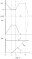
- Figure 4 schematically illustrates the result of the steps of the method according to the present disclosure over time t.
- the top drawing represents the state of the clutch, which can be varied between a closed state and an open state.
- the middle drawing represents the torque transferred by the clutch to the combustion engine.
- the bottom drawing represents the rotational speed ⁇ E of the combustion engine, and the rotational speed ⁇ I of the input shaft of the gearbox, respectively.
- t 0 the combustion engine is in a non-rotating state and the control of the clutch, in response to an instruction for start of the combustion engine, to a partially closed state is initiated.
- the torque transferred by the clutch will increase as a result of the change of state of the clutch (se shown in the middle drawing).
- t 1 the clutch has reached a partially closed state (as shown in the top drawing), such as a target partially closed state TS..
- the combustion engine will thereby start rotating (as shown in the bottom drawing) as a result of the transferred torque.
- t 2 the combustion engine has been started and can be accelerated by control of the fuel injection.
- the rotational speed of the combustion engine has at t 2 however not yet reached a rotational speed synchronised with the rotational speed of the input shaft of the gearbox (as shown in the bottom drawing).
- the control of the clutch to the open state is initiated (as shown in the top drawing) and the torque transferred by the clutch to the combustion engine will therefore start to decrease (as shown in the middle drawing).
- the opening of the clutch to the open state is preferably made as quickly as possible.
- t 3 the combustion engine is accelerated by means of control of the fuel injection to the combustion engine.
- the rotational speed of the combustion engine has been synchronised to the rotational speed of the input shaft of the gearbox (as shown in the bottom drawing) and the clutch can be controlled from the open state to the completely closed state (shown by dotted line in top drawing) so that the torque generated by the combustion engine can be transferred to the driving wheels. If the clutch is controlled to the completely closed state after t 3 , the torque transferred by the clutch will increase (as shown by the dotted line in middle drawing).
- FIG. 5 schematically illustrates an exemplifying embodiment of a device 500.
- the control device 100 described above may for example comprise the device 500, consist of the device 500, or be comprised in the device 500.
- the device 500 comprises a non-volatile memory 520, a data processing unit 510 and a read/write memory 550.
- the non-volatile memory 520 has a first memory element 530 in which a computer program, e.g. an operating system, is stored for controlling the function of the device 500.
- the device 500 further comprises a bus controller, a serial communication port, I/O means, an A/D converter, a time and date input and transfer unit, an event counter and an interruption controller (not depicted).
- the non-volatile memory 520 has also a second memory element 540.
- a computer program P that comprises routines for starting a combustion engine of a vehicle powertrain during free-wheeling with engine off.
- the vehicle powertrain comprises a combustion engine comprising an output shaft.
- the vehicle powertrain further comprises a gearbox arranged to selectively transfer torque between the combustion engine and at least one driving wheel.
- the gearbox comprises an input shaft.
- the vehicle powertrain further comprises a clutch arranged between the combustion engine and the gearbox. The clutch is connected to the input shaft of the gearbox and the output shaft of the combustion engine.
- the computer program comprises routines/instructions for, in response to an instruction for starting the combustion engine, controlling the clutch to a partially closed state so as to transfer torque from the input shaft of the gearbox to the combustion engine, thereby starting the combustion engine.
- the computer program further comprises routines/instructions for, when the combustion engine has started but prior to the output shaft of the combustion engine has reached a rotational speed synchronized with the rotational speed of the input shaft of the gearbox, controlling the clutch to an open state.
- the computer program comprises routines/instructions for synchronizing the speed of the combustion engine to the speed of the input shaft of the gearbox through control of fuel injection to the combustion engine.
- the program P may be stored in an executable form or in a compressed form in a memory 560 and/or in a read/write memory 550.
- the data processing unit 510 may perform certain functions. For example, the data processing unit 510 may effect a certain part of the program stored in the memory 560 or a certain part of the program stored in the read/write memory 550.
- the data processing device 510 can communicate with a data port 599 via a data bus 515.
- the non-volatile memory 520 may be intended for communication with the data processing unit 510 via a data bus 512.
- the separate memory 560 may be intended to communicate with the data processing unit 510 via a data bus 511.
- the read/write memory 550 may be adapted to communicate with the data processing unit 510 via a data bus 514.
- Parts of the methods herein described may be effected by the device 500 by means of the data processing unit 510 which runs the program stored in the memory 560 or the read/write memory 550. When the device 500 runs the program, methods herein described are executed.
Landscapes
- Engineering & Computer Science (AREA)
- Chemical & Material Sciences (AREA)
- Combustion & Propulsion (AREA)
- Mechanical Engineering (AREA)
- Transportation (AREA)
- Automation & Control Theory (AREA)
- General Engineering & Computer Science (AREA)
- Human Computer Interaction (AREA)
- Control Of Vehicle Engines Or Engines For Specific Uses (AREA)
- Electrical Control Of Air Or Fuel Supplied To Internal-Combustion Engine (AREA)
- Hydraulic Clutches, Magnetic Clutches, Fluid Clutches, And Fluid Joints (AREA)
Description
- The present disclosure relates in general to method for starting a combustion engine of a vehicle powertrain during free-wheeling with engine off. The present disclosure further relates in general to a control device configured to start a combustion engine of a vehicle powertrain during free-wheeling with engine off, and a vehicle comprising such a control device. The present disclosure further relates in general to a computer program and a computer-readable medium.
- The continuous strive of vehicle manufactures to reduce fuel consumption has led to a desire to be able to reduce the speed of the combustion engine to a minimum, typically idle speed, in situations where no driving torque is necessary for continued travel of the vehicle. An example of a situation where no driving torque is necessary for continued travel of the vehicle may be during downhill travel. A reduction of the speed of the combustion engine to a minimum in such situations may be achieved by opening the vehicle powertrain, either by opening the clutch or putting the gearbox in neutral, so as to avoid engine braking which would occur if the vehicle powertrain would be closed. This operation mode of the vehicle powertrain is sometimes referred to as free-wheeling and is commonly implemented in heavy vehicles today.
- By shutting down the combustion engine when there is no need for a driving torque to be transferred to the driving wheels, instead of running the combustion engine at idle speed as described above, even more fuel can be saved. Such an operation mode may be referred to as free-wheeling with engine off.
- Free-wheeling with engine off requires that the combustion engine can be quickly and efficiently started when there is a need for transferring driving torque to the driving wheels again. The combustion engine may for example be started by means of starting systems adapted therefore. However, available starting systems are either insufficient to handle the high number of starts required in order to implement free-wheeling with engine off and/or come at a high expense.
- Alternatively, the combustion engine may be started using the clutch. Thereby, it is possible to avoid the extra cost for an upgraded, more durable, starter system that could handle the high number of starts required. Start of the combustion engine by means of the clutch is achieved by partially closing the clutch so as to transfer torque from the input shaft of the gearbox to the output shaft of the combustion engine, thereby dragging the combustion engine.
- Starting the combustion engine using the clutch has however two major drawbacks. The first drawback is clutch wear. Albeit an engine start only imparts a moderate clutch wear, the life length of the clutch may be significantly reduced due to the high total number of starts of the combustion engine required if free-wheeling with engine off is implemented. The second drawback is handling effects. Since the energy required to start the combustion engine using the clutch is taken from the drive wheel, the start of the combustion engine thus results in a braking force on the drive wheels. This might in turn, in some situations, affect the lateral stability of the vehicle. Therefore, it is important to have a start procedure that results in minimum wear of the clutch and force on the driving wheels.
-
EP 2 497 940 A2 -
US 2017144531 A2 discloses a drive system for a vehicle includes an engine, a torque converter that receives power from the engine, an output shaft that transmits torque, transmitted from the torque converter, to a drive wheel, a motor generator that is able to transmit power to the output shaft, and a first clutch provided between the engine and the torque converter and configured to allow or interrupt transmission of power between the engine and the torque converter. - The object of the present invention is to address the problem of the high number of starts of the combustion engine required if fully implementing free-wheeling with engine off by providing an efficient and reliable start of the combustion engine in conjunction with free-wheeling with engine off.
- The object is achieved by means of the subject-matter of the appended independent claims.
- In accordance with the present disclosure, a method for starting a combustion engine of a vehicle powertrain during free-wheeling with engine off is provided. The method is performed by a control device. The vehicle powertrain comprises a combustion engine comprising an output shaft. The vehicle powertrain further comprises a gearbox arranged to selectively transfer torque between the combustion engine and at least one driving wheel, the gearbox comprising an input shaft. The vehicle powertrain further comprises a clutch arranged between the combustion engine and the gearbox. The clutch is connected to the input shaft of the gearbox and the output shaft of the combustion engine. The method comprises the steps of:
- in response to an instruction for start of the combustion engine, controlling the clutch to a partially closed state so as to transfer torque from the input shaft of the gearbox to the combustion engine, thereby starting the combustion engine;
- when the combustion engine has started, but prior to the output shaft of the combustion engine has reached a rotational speed synchronised with the rotational speed of the input shaft of the gearbox, controlling the clutch to an open state; and
- synchronising the speed of the combustion engine to the speed of the input shaft of the gearbox through control of fuel injection to the combustion engine,
- In accordance with the method according to the present disclosure, the combustion engine is started by means of the clutch and there is therefore no need for a separate or upgraded starting system for starting the combustion engine in conjunction with free-wheeling with engine off. Therefore, the load on a starter system adapted to start the combustion engine, if present, is reduced. Such a starter system may be used only for starting the combustion engine when the vehicle has been at standstill with engine off.
- Furthermore, by means of the present method, the wear of the clutch is reduced since the clutch is only used for a part of the starting sequence. More specifically, in contrast to previously known methods, the clutch is not partially (or fully) engaged during the whole starting sequence leading up to a rotational speed of the combustion engine at which the clutch can be fully engaged and the torque from the combustion engine transmitted to the driving wheels. Instead, the clutch will be opened after the combustion engine has started, but prior to the combustion engine has reached the rotational speed at which it is synchronised with the rotational speed of the input shaft of the gearbox.
- The present method also has the advantage of significantly reducing the risk of loss of lateral stability during the starting sequence of the combustion engine. This is due to the energy transferred from the driving wheels in order to drag the combustion engine being considerably reduced as a result of opening of the clutch during a part of the starting sequence.
- The step of controlling the clutch to an open state may be performed in response to an indication from a management system of the combustion engine that the combustion engine may be accelerated by control of fuel injection. This has the advantage of ensuring that the clutch can be safely opened without failure to start the combustion engine. In other words, it can be ensured that the clutch is opened only after sufficient torque has been transferred from the input shaft of the gearbox to the output shaft of the combustion engine to start the combustion engine. This in turn ensures a safe start of the combustion engine.
- The step of controlling the clutch to an open state may be performed in response to an indication that the rotational speed of the combustion engine has reached a predetermined rotational speed threshold value. The rotational speed of the combustion engine can easily and quickly be determined by means of already present sensors normally utilised for the purpose of control of combustion engine. Therefore, an early indication of when the combustion engine has sufficient rotational speed to be accelerated by control of fuel injection can be determined. Therefore, the control of the clutch to an open state can be performed at an early stage of the starting sequence. This in turn further reduces the wear of the clutch.
- The predetermined rotational speed threshold value may for example correspond to a rotational speed lower than, or equal to, the idle speed of the combustion engine. At idle speed, it is well known that the combustion engine may be accelerated by control of fuel injection. However, for the purpose of reducing the wear of the clutch and reduce the risk of problems with lateral stability, it is advantageous to open the clutch as early as possible. Therefore, the predetermined rotational speed threshold value could advantageously be lower than the idle speed.
- The step of controlling the clutch to the open state is initiated in response to an indication that a predetermined condition for opening of the clutch is fulfilled. This enables initiating the opening of the clutch as early as possible, which in turn further reduces the wear of the clutch and the risk of loss in lateral stability. The predetermined condition for opening of the clutch is based on a prediction that the torque transferred to the combustion engine during opening of the clutch is sufficient for the combustion engine to reach a state at which it may be accelerated by control of fuel injection. Alternatively, or additionally, the predetermined condition for opening of the clutch may be based on a prediction that the time it takes to open the clutch is sufficiently long for the combustion engine to reach a state at which the combustion engine may be accelerated by control of fuel injection.
- The step of controlling the clutch to a partially closed state may be performed to a predetermined transfer torque. Thereby, it may be ensured that the torque transferred from the input shaft of the gearbox to the combustion engine is sufficient to drag the combustion engine. This in turn increases the reliability of the start of the combustion engine.
- The step of controlling the clutch to the open state may be performed after an indication that a first fuel injection to the combustion engine has occurred. Thereby, the risk of the clutch being opened too early during the starting sequence may be minimised. This in turn increases the reliability of the start of the combustion engine.
- The method may further comprise a step of, when the rotational speed of the output shaft of the combustion engine is synchronised to the speed of the input shaft of the gearbox, controlling the clutch from the open state to a closed state. Thereby, driving torque from the combustion engine may be fully transferred to the driving wheels of the vehicle powertrain when the free-wheeling operation with engine off has been terminated.
- The present disclosure further relates to a computer program comprising instructions, which when executed by a control device, cause the control device to perform the method for starting a combustion engine of a vehicle powertrain during free-wheeling with engine off as described above.
- The present disclosure further relates to a computer-readable medium comprising instructions, which when executed by a control device, cause the control device to perform the method for starting a combustion engine of a vehicle powertrain during free-wheeling with engine off as described above.
- Furthermore, in accordance with the present disclosure, a control device configured to start a combustion engine of a vehicle powertrain during free-wheeling with engine off is provided. The vehicle powertrain comprises a combustion engine comprising an output shaft. The vehicle powertrain further comprises a gearbox arranged to selectively transfer torque between the combustion engine and at least one driving wheel, the gearbox comprising an input shaft. The vehicle powertrain further comprises a clutch arranged between the combustion engine and the gearbox. The clutch is connected to the input shaft of the gearbox and the output shaft of the combustion engine. The control device is configured to, in response to an instruction to start the combustion engine, control the clutch to a partially closed state so as to transfer torque from the input shaft of the gearbox to the combustion engine, thereby starting the combustion engine. The control device is further configured to control the clutch to an open state when the combustion engine has started, but prior to the output shaft of the combustion engine has reached a rotational speed synchronised with the rotational speed of the input shaft of the gearbox. The control device is further configured to, during and/or after controlling the clutch to the open state, synchronise the rotational speed of the combustion engine to the rotational speed of the input shaft of the gearbox through control of fuel injection to the combustion engine.
- The control device has the same advantages as described above with regard to the corresponding method for starting a combustion engine of a vehicle powertrain during free-wheeling with engine off.
- The control device may be configured to control the clutch to the open state in response to an indication from a management system of the combustion engine that the combustion engine may be accelerated by control of fuel injection and/or in response to an indication that the rotational speed of the combustion engine has reached a predetermined rotational speed threshold value. The predetermined rotational speed threshold value may correspond to a rotational speed lower than, or equal to, the idle speed of the combustion engine.
- The control device may be configured to initiate the control of the clutch to the open state is response to an indication that a predetermined condition for opening of the clutch is fulfilled. The predetermined condition for opening of the clutch may for example be based on a prediction that the torque transferred to the combustion engine during opening of the clutch is sufficient for the combustion engine to reach a state at which it may be accelerated by control of fuel injection. Alternatively, or additionally, the predetermined condition for opening of the clutch may for example be based on a prediction that the time it takes to open the clutch is sufficiently long for the combustion engine to reach a state at which the combustion engine may be accelerated by control of fuel injection.
- The control device may further be configured to control the clutch to the partially closed state to a predetermined transfer torque.
- The control device may further be configured to control the clutch from the open state to a closed state when the rotational speed of the output shaft of the combustion engine is synchronised to the rotational speed of the input shaft of the gearbox.
- Moreover, the present disclosure relates to a vehicle comprising a vehicle powertrain. The vehicle further comprises the control device configured to start a combustion engine of a vehicle powertrain during free-wheeling with engine off as described above.
-
-
Fig. 1 schematically illustrates a side view of an example of a vehicle; -
Fig. 2 schematically illustrates an example of a vehicle powertrain; -
Fig. 3 represents a flowchart schematically illustrating an exemplifying embodiment of a method; -
Fig. 4 schematically illustrates the result of the steps of the method according to the present disclosure over time; -
Fig. 5 schematically illustrates a device that may constitute, comprise or be a part of a control device configured to start a combustion engine of a vehicle powertrain during free-wheeling with engine off. - The invention will be described in more detail below with reference to exemplifying embodiments and the accompanying drawings. The invention is however not limited to the exemplifying embodiments discussed and/or shown in the drawings, but may be varied within the scope of the appended claims. Furthermore, the drawings shall not be considered drawn to scale as some features may be exaggerated in order to more clearly illustrate the invention or features thereof.
- The present disclosure provides a method for starting a combustion engine of a vehicle powertrain in conjunction with free-wheeling with engine off. In other words, the present disclosure relates to a method for starting a combustion engine when free-wheeling with engine off is to be terminated. During free-wheeling with engine off, there is no driving torque provided from any propulsion unit of the vehicle powertrain to the driving wheels. The reason for ending an operation of free-wheeling with engine off is typically that a driving torque from the combustion engine is necessary in order for the vehicle not to unintentionally lose traveling speed.
- The vehicle powertrain comprises a combustion engine having an output shaft. The combustion engine may be the only propulsion unit of the vehicle powertrain. Alternatively, the vehicle powertrain may comprise one or more further propulsion units, such as an electrical machine, if desired. The vehicle powertrain further comprises a gearbox arranged to selectively transfer torque between the combustion engine and at least one driving wheel of the vehicle powertrain. The gearbox comprises an input shaft. The vehicle powertrain further comprises a clutch arranged between the combustion engine and the gearbox. The clutch is connected to the input shaft of the gearbox and to the output shaft of the combustion engine. The clutch may be a friction clutch.
- The clutch may be controlled to different states. If the clutch is in an open state, the operative connection between the combustion engine and the driving wheel(s) is interrupted. When the clutch is in the completely closed state, the operative connection between the combustion engine and the driving wheel(s) is essentially rigid. In other words, the clutch is in a non-slipping state in the completely closed state. The clutch may also be controlled to various partially closed states, in which the clutch is slipping. In the partially closed state, the clutch may, depending on how much the clutch is closed, transfer different amounts of torque between the output shaft of the combustion engine and the input shaft of the gearbox. Thus, the amount of torque transferrable by a clutch may be controlled by controlling a distance between the friction plates of a friction clutch.
- The method for starting a combustion engine of a vehicle powertrain in conjunction with free-wheeling with engine off comprises a step of, in response to an instruction for start of the combustion engine, controlling the clutch to a partially closed state. Thereby, the clutch transfers torque from the input shaft of the gearbox (which is in a rotating state due to the free-wheeling operation) to the output shaft of combustion engine. Thereby, the combustion engine is started. The instruction for start of the combustion engine may for example be generated by a cruise control system of the vehicle powertrain or by any other means known in the art. The instruction for start of the combustion engine may typically be generated when there is an expected future need for driving torque from the combustion engine. In other words, the instruction for start of the combustion engine is typically generated before the operation of free-wheeling with engine off is terminated.
- The clutch may in the above described step be controlled to a partially closed state corresponding to a predetermined transfer torque. This can be achieved by controlling the position of the constituent components of the clutch, or, in other words, by controlling the clutch to a predetermined slippage. The predetermined transfer torque is chosen to a torque sufficient to initiate a rotation of the output shaft of the combustion engine such that the combustion engine is started. Such a torque may be determined in any previously known manner therefore, for example by measuring this torque on engines in test beds as part of the calibration for that engine type.
- The method further comprises a step of controlling the clutch to the open state when the combustion engine has been started as described above, but prior to the rotational speed of the output shaft of the combustion engine has reached a rotational speed synchronised to the rotational speed of the input shaft of the gearbox. In other words, the clutch is opened before the combustion engine has reached the synchronised speed.
- The step of controlling the clutch to the open state may be performed in response to an indication from a management system of the combustion engine that the combustion engine may be accelerated by control of fuel injection. Thereby, it is ensured that the clutch is not opened at a too early stage, which could otherwise result in a failure of the start of the combustion engine.
- Alternatively, the step of controlling the clutch to the open state may be performed in response to an indication that the rotational speed of the combustion engine has reached a predetermined rotational speed threshold value. This may, in comparison to the alternative of controlling the clutch to an open state in response to an indication from a management system of the combustion engine, enable an earlier initiation of the opening of the clutch and thereby lower wear of the clutch.
- However, the reliability may be somewhat reduced compared to the formed alternative. The predetermined rotational speed threshold value may be a rotational speed value at which it is previously known that the combustion engine has a sufficient rotational speed for allowing acceleration by control of fuel injection to the combustion engine. It should be recognised that the predetermined rotational speed threshold value will be dependent of the type of combustion engine. It is well known that a combustion engine can be accelerated by control of fuel injection when at idle speed. However, a combustion engine can in general be accelerated at much lower rotational speeds by control of fuel injection. In order to reduce the wear of the clutch and the risk of loss of lateral stability as much as possible, there is a desire to open the clutch as early as possible. Therefore, the predetermined rotational speed threshold may suitably be a rotational speed lower than the idle speed of the combustion engine. By way of example, the predetermined rotational speed threshold value may be 80% or less of the idle speed of the combustion engine. In some cases, the predetermined rotational speed threshold value may even be as low as about half the idle speed of the combustion engine.
- It should also be recognised that it is naturally also possible that, albeit less preferred as it in some cases may cause a delay in the opening of the clutch, the step of controlling the clutch to the open state may be performed in response to both an indication from the management system of the combustion engine and an indication that the rotational speed of the combustion engine has reached a predetermined rotational speed threshold value, if desired.
- In view of the fact that control of the clutch to the different states takes some time (albeit very short), the opening of the clutch may be initiated before the combustion engine can actually be accelerated by control of fuel injection as long as the combustion engine will reach a state at which it can be accelerated by control of fuel during the time it takes to open the clutch or at the point in time at which the clutch reaches the open state. Therefore, the step of controlling the clutch to the open state may be initiated in response to an indication that a predetermined condition for opening of the clutch is fulfilled. The predetermined condition for opening of the clutch may for example be based on a prediction that the torque transferred to the combustion engine during the opening of the clutch (i.e. prior to conclusion of the opening of the clutch) is sufficient for the combustion engine to reach a state at which it may be accelerated by control of fuel injection. Such a prediction may for example be prepared in advance for any possible condition of the vehicle powertrain and stored in a look-up table for subsequent use in the method as described herein. Alternatively, or additionally, the predetermined condition for opening of the clutch may be based on a prediction that the time it takes to open the clutch from the partially closed state is sufficiently long for the combustion engine to reach a state at which it may be accelerated by control of fuel injection.
- The step of controlling the clutch to the open state may suitably be performed only after an indication that a first fuel injection to the combustion engine has occurred. Thereby, it may for example be ensured that the opening of the clutch is not performed too early in the starting sequence and that the combustion engine may be accelerated by control of fuel injection.
- The step of controlling the clutch to the open state is preferably performed immediately after the step of controlling the clutch to the partially closed state for the purpose of starting the combustion engine. In other words, the opening of the clutch is preferably conducted as soon as the combustion engine has reached, or is expected to reach before the clutch is in the open state, a state at which it may be accelerated by control of fuel injection.
- The method further comprises a step of synchronising the speed of the combustion engine to the speed of the input shaft of the gearbox by means of controlling fuel injection to the combustion engine. In this context, synchronising is considered to mean that the rotational speed of the combustion engine is brought to a suitable rotational speed for enabling a smooth closing of the clutch without causing discomfort for a driver of the vehicle or risk for damage to the clutch. It is however not necessary that the combustion engine is rotating with exactly the same speed as the input shaft of the gearbox. In other words, the method comprises a step of controlling the fuel injection to the combustion engine so as to accelerate the combustion engine for the purpose of reaching a rotational speed of the combustion engine which is the same or essentially the same as the rotational speed of the input shaft of the gearbox.
- The step of synchronising the speed of the combustion engine to the speed of the input shaft of the gearbox through control of fuel injection to the combustion engine is performed after the combustion engine has started, and may be initiated before the clutch has reached the completely open state. In other words, the step of controlling the clutch to the open state and the step of synchronising the speed of the combustion engine may be conducted simultaneously for a short duration of the starting sequence. However, during at least a portion of the step of synchronising the speed of the combustion engine to the speed of the input shaft of the gearbox through control of fuel injection, the clutch is in the open state. Suitably, the aim is for the clutch to be in the open state during as much as possible of said step of synchronising the speed of the combustion engine. This significantly reduces the wear of the clutch and the risk for loss in lateral stability.
- In summary, the present method provides a starting sequence for the combustion engine comprising two consecutive phases. In the first initial phase, the combustion engine is started by a dragging torque from the driving wheel(s) resulting from the clutch being in a partially closed state. In the second phase, following the first phase, the clutch is in an open state and the combustion engine is accelerated by its own by controlling the fuel injection until it has reached a synchronised speed with the input shaft of the gearbox.
- When the rotational speed of the combustion engine has been synchronised to the rotational speed of the input shaft of the gearbox, the clutch may be controlled from the open state to a completely closed state. Thereby, torque may be transferred from the combustion engine to the driving wheel(s) and hence propulsion of the vehicle powertrain may thereby be effectuated by means of the combustion engine when the free-wheeling with engine off operation is terminated.
- Moreover, in accordance with the present disclosure, a control device configured to start a combustion engine of a vehicle powertrain in conjunction with free-wheeling with engine off is provided. The control device may be configured to perform any one of the steps described above.
- More specifically, the control device configured to start a combustion engine of a vehicle powertrain during freewheeling with engine off is configured to:
- in response to an instruction to start the combustion engine, control the clutch to a partially closed state so as to transfer torque from the input shaft of the gearbox to the combustion engine, thereby starting the combustion engine,
- control the clutch to an open state when the combustion engine has started, but prior to the output shaft of the combustion engine has reached a rotational speed synchronised with the rotational speed of the input shaft of the gearbox, and
- during and/or after controlling the clutch to the open state, synchronise the rotational speed of the combustion engine to the rotational speed of the input shaft through control of fuel injection to the combustion engine.
-
Figure 1 schematically illustrates a side view of an example of avehicle 1. Thevehicle 1 comprises apowertrain 3 comprising aninternal combustion engine 2 and agearbox 4. A clutch (shown inFigure 2 ) may be arranged between theinternal combustion engine 2 and thegearbox 4. Thegearbox 4 is connected to thedriving wheels 5 of thevehicle 1 via anoutput shaft 6 of thegearbox 4. Thegearbox 4 is adapted to selectively transfer torque between thecombustion engine 2 and thedriving wheels 5 during operation of the vehicle. Thevehicle 1 may further comprisenon-driving wheels 7. - The
vehicle 1 may be, but is not limited to, a heavy vehicle, e.g. a truck or a bus. Furthermore, the vehicle may be a hybrid vehicle comprising an electric machine (not shown) in addition to theinternal combustion engine 2. -
Figure 2 schematically illustrates an exemplifying embodiment of avehicle powertrain 3, such as a powertrain of thevehicle 1 shown inFigure 1 . Thepowertrain 3 comprises acombustion engine 2 having an output shaft 8. The vehicle powertrain may further comprise amanagement system 20 of thecombustion engine 2. Thepowertrain 3 further comprises agearbox 4 comprising aninput shaft 10. Thepowertrain 3 further comprises a clutch 9 arranged between thecombustion engine 2 and thegearbox 4. Theclutch 9 is connected to theinput shaft 10 of the gearbox and the output shaft 8 of the combustion engine. Thegearbox 4 may for example be an automated manual gearbox (AMT). The clutch 9 may be a friction clutch. - The
vehicle powertrain 3 furthermore comprises acontrol device 100, as will be described in more detail below. Thecontrol device 100 is configured to control at least a part of the powertrain. More specifically, the control device may be configured to control theclutch 9 and thecombustion engine 2. Thecontrol device 100 is configured to start thecombustion engine 2 during free-wheeling with engine off. The control device may optionally be configured to control further operations of the vehicle powertrain, if desired. - The
control device 100 may comprise one or more control units. In case of thecontrol device 100 comprising a plurality of control units, each control unit may be configured to control a certain function or a certain function may be divided between two or more of the control units. Thecontrol device 100 may be separate from themanagement system 20 of thecombustion engine 2, comprise themanagement system 20, or be comprised in themanagement system 20 of thecombustion engine 2, as desired. - The performance of the method for starting a combustion engine as disclosed herein may be governed by programmed instructions. These programmed instructions typically take the form of a computer program which, when executed in or by a control device, causes the control device to effect desired forms of control action. Such instructions may typically be stored on a computer-readable medium.
-
Figure 3 represents a flowchart schematically illustrating an exemplifying embodiment of the method for starting a combustion engine of a vehicle powertrain (for example thevehicle powertrain 3 shown inFigure 2 ) in conjunction with free-wheeling with engine. InFigure 3 , optional steps of the method are shown with dashed boxes. At the start of the method, the vehicle powertrain (and hence the vehicle) is in an operation mode of free-wheeling with engine off. This means for example that the input shaft of the gearbox is rotating but the output shaft of the combustion engine is in a non-rotating state or at least essentially non-rotating state. - The method may comprise an initial step S101 of determining or detecting an instruction for start of the combustion engine. The instruction for start of the combustion engine may for example be generated by a cruise control system or the like.
- The method comprises a step S102 of, in response to an instruction for start of the combustion engine, controlling the clutch to a partially closed state. In the partially closed state, the clutch transfers torque from the input shaft of the gearbox to the combustion engine (more specifically to the output shaft of the combustion engine). Thereby, the combustion engine is started. The partially closed state may correspond to a state imparting a predetermined transfer torque of the clutch.
- After step S102, the method may comprise a step S103 of determining that the combustion engine has started. This may be performed for example by determining an indication from a management system of the combustion engine that the combustion engine may be accelerated by control of fuel injection, or by determining an indication that the rotational speed of the combustion engine has reached a predetermined rotational speed threshold value.
- The method further comprises a step S104 of controlling the clutch to an open state. Step S104 is performed when the combustion engine has been started, but prior to the output shaft of the combustion engine has reached a rotational speed synchronised with the rotational speed of the input shaft of the gearbox.
- The method further comprises a step S105 of synchronising the speed of the combustion engine to the speed of the input shaft of the gearbox through control of fuel injection to the combustion engine.
- When the rotational speed of the output shaft of the combustion engine has been synchronised to the rotational speed of the input shaft of the gearbox, the method may comprise a step S106 of controlling the clutch to a completely closed state. Thereby, the torque generated by the combustion engine may be fully utilised to drive the driving wheels of the vehicle powertrain. In other words, the operation mode of free-wheeling with engine off is terminated.
-
Figure 4 schematically illustrates the result of the steps of the method according to the present disclosure over time t. The top drawing represents the state of the clutch, which can be varied between a closed state and an open state. The middle drawing represents the torque transferred by the clutch to the combustion engine. The bottom drawing represents the rotational speed ωE of the combustion engine, and the rotational speed ωI of the input shaft of the gearbox, respectively. - At a first point in time, t0, the combustion engine is in a non-rotating state and the control of the clutch, in response to an instruction for start of the combustion engine, to a partially closed state is initiated. The torque transferred by the clutch will increase as a result of the change of state of the clutch (se shown in the middle drawing). At a second point in time, t1, the clutch has reached a partially closed state (as shown in the top drawing), such as a target partially closed state TS.. The combustion engine will thereby start rotating (as shown in the bottom drawing) as a result of the transferred torque. At a third point in time, t2, the combustion engine has been started and can be accelerated by control of the fuel injection. The rotational speed of the combustion engine has at t2 however not yet reached a rotational speed synchronised with the rotational speed of the input shaft of the gearbox (as shown in the bottom drawing). At t2, the control of the clutch to the open state is initiated (as shown in the top drawing) and the torque transferred by the clutch to the combustion engine will therefore start to decrease (as shown in the middle drawing). The opening of the clutch to the open state is preferably made as quickly as possible. Between t2 and a fourth point in time, t3, the combustion engine is accelerated by means of control of the fuel injection to the combustion engine. At the fourth point in time, t3, the rotational speed of the combustion engine has been synchronised to the rotational speed of the input shaft of the gearbox (as shown in the bottom drawing) and the clutch can be controlled from the open state to the completely closed state (shown by dotted line in top drawing) so that the torque generated by the combustion engine can be transferred to the driving wheels. If the clutch is controlled to the completely closed state after t3, the torque transferred by the clutch will increase (as shown by the dotted line in middle drawing).
-
Figure 5 schematically illustrates an exemplifying embodiment of adevice 500. Thecontrol device 100 described above may for example comprise thedevice 500, consist of thedevice 500, or be comprised in thedevice 500. - The
device 500 comprises anon-volatile memory 520, adata processing unit 510 and a read/write memory 550. Thenon-volatile memory 520 has afirst memory element 530 in which a computer program, e.g. an operating system, is stored for controlling the function of thedevice 500. Thedevice 500 further comprises a bus controller, a serial communication port, I/O means, an A/D converter, a time and date input and transfer unit, an event counter and an interruption controller (not depicted). Thenon-volatile memory 520 has also asecond memory element 540. - There is provided a computer program P that comprises routines for starting a combustion engine of a vehicle powertrain during free-wheeling with engine off. The vehicle powertrain comprises a combustion engine comprising an output shaft. The vehicle powertrain further comprises a gearbox arranged to selectively transfer torque between the combustion engine and at least one driving wheel. The gearbox comprises an input shaft. The vehicle powertrain further comprises a clutch arranged between the combustion engine and the gearbox. The clutch is connected to the input shaft of the gearbox and the output shaft of the combustion engine. The computer program comprises routines/instructions for, in response to an instruction for starting the combustion engine, controlling the clutch to a partially closed state so as to transfer torque from the input shaft of the gearbox to the combustion engine, thereby starting the combustion engine. The computer program further comprises routines/instructions for, when the combustion engine has started but prior to the output shaft of the combustion engine has reached a rotational speed synchronized with the rotational speed of the input shaft of the gearbox, controlling the clutch to an open state. Moreover, the computer program comprises routines/instructions for synchronizing the speed of the combustion engine to the speed of the input shaft of the gearbox through control of fuel injection to the combustion engine.
- The program P may be stored in an executable form or in a compressed form in a
memory 560 and/or in a read/write memory 550. - The
data processing unit 510 may perform certain functions. For example, thedata processing unit 510 may effect a certain part of the program stored in thememory 560 or a certain part of the program stored in the read/write memory 550. - The
data processing device 510 can communicate with adata port 599 via adata bus 515. Thenon-volatile memory 520 may be intended for communication with thedata processing unit 510 via adata bus 512. Theseparate memory 560 may be intended to communicate with thedata processing unit 510 via adata bus 511. The read/write memory 550 may be adapted to communicate with thedata processing unit 510 via adata bus 514. - When data are received on the
data port 599, they may be stored temporarily in thesecond memory element 540. When input data received have been temporarily stored, thedata processing unit 510 may be prepared to effect code execution according to a computer program comprising program code for causing a control device to perform the method (or parts thereof) for controlling a braking system for a vehicle as described herein. - Parts of the methods herein described may be effected by the
device 500 by means of thedata processing unit 510 which runs the program stored in thememory 560 or the read/write memory 550. When thedevice 500 runs the program, methods herein described are executed.
Claims (15)
- A method for starting a combustion engine (2) of a vehicle powertrain (3) during free-wheeling with engine off, the method being performed by a control device (100);the vehicle powertrain (3) comprising:a combustion engine (2) comprising an output shaft (8),a gearbox (4) arranged to selectively transfer torque between the combustion engine (2) and at least one driving wheel (5), the gearbox comprising an input shaft (10), anda clutch (9) arranged between the combustion engine (2) and the gearbox (4), the clutch connected to the input shaft (10) of the gearbox and the output shaft (8) of the combustion engine;the method comprising the steps of:- in response to an instruction for start of the combustion engine (2), controlling the clutch (9) to a partially closed state so as to transfer torque from the input shaft (10) of the gearbox to the combustion engine (2), thereby starting the combustion engine (2);- when the combustion engine (2) has started, but prior to the output shaft (8) of the combustion engine has reached a rotational speed synchronised with the rotational speed of the input shaft (10) of the gearbox, controlling the clutch (9) to an open state;- synchronising the speed of the combustion engine (2) to the speed of the input shaft (10) of the gearbox through control of fuel injection to the combustion engine (2),wherein the step of controlling the clutch (9) to the open state is initiated in response to an indication that a predetermined condition for opening of the clutch (9) is fulfilled, and characterized in thatthe predetermined condition for opening of the clutch (9) is based on a prediction that the torque transferred to the combustion engine (2) during opening of the clutch (9) is sufficient for the combustion engine (2) to reach a state at which it may be accelerated by control of fuel injection.
- The method according to claim 1, wherein the step of controlling the clutch (9) to an open state is performed in response to an indication from a management system (20) of the combustion engine that the combustion engine (2) may be accelerated by control of fuel injection.
- The method according to any one of claims 1 or 2, wherein the step of controlling the clutch (9) to an open state is performed in response to an indication that the rotational speed of the combustion engine (2) has reached a predetermined rotational speed threshold value.
- The method according to claim 3, wherein the predetermined rotational speed threshold value corresponds to a rotational speed lower than, or equal to, the idle speed of the combustion engine.
- The method according to any one of the preceding claims, wherein the predetermined condition for opening of the clutch (9) is based on a prediction that the time it takes to open the clutch (9) is sufficiently long for the combustion engine (2) to reach a state at which the combustion engine (2) may be accelerated by control of fuel injection.
- The method according to any one of the preceding claims, wherein the step of controlling the clutch (9) to the partially closed state is performed to a predetermined transfer torque.
- The method according to any one of the preceding claims, wherein the step of controlling the clutch (9) to the open state is performed after an indication that a first fuel injection to the combustion engine (2) has occurred.
- The method according to any one of the preceding claims, further comprising- when the rotational speed of the output shaft (8) of the combustion engine (2) is synchronised to the rotational speed of the input shaft (10) of the gearbox (4), controlling the clutch (9) from the open state to a closed state.
- A computer program comprising instructions, which when executed by a control device, cause the control device to perform the method according to any one of the preceding claims.
- A computer-readable medium comprising instructions, which when executed by a control device, cause the control device to perform the method according to any one of claims 1 to 10.
- A control device (100) configured to start a combustion engine (2) of a vehicle powertrain (3) during free-wheeling with engine off;the vehicle powertrain (3) comprising:a combustion engine (2) comprising an output shaft (8),a gearbox (4) arranged to selectively transfer torque between the combustion engine (2) and at least one driving wheel (5), the gearbox comprising an input shaft (10), anda clutch (9) arranged between the combustion engine (2) and the gearbox (4), the clutch connected to the input shaft (10) of the gearbox and the output shaft (8) of the combustion engine;the control device (100) configured to, in response to an instruction for start of the combustion engine (2), control the clutch (9) to a partially closed state so as to transfer torque from the input shaft (10) of the gearbox to the combustion engine (2), thereby starting the combustion engine (2);the control device (100) further configured to control the clutch (9) to an open state when the combustion engine (2) has started, but prior to the output shaft (8) of the combustion engine has reached a rotational speed synchronised with the rotational speed of the input shaft (10) of the gearbox;- the control device (100) further configured to, during and/or after controlling the clutch (9) to the open state, synchronise the rotational speed of the combustion engine (2) to the rotational speed of the input shaft (10) of the gearbox (4) through control of fuel injection to the combustion engine (2),wherein the control device is configured to initiate the control of the clutch (9) to the open state is response to an indication that a predetermined condition for opening of the clutch (9) is fulfilled, and characterized in thatthe predetermined condition for opening of the clutch (9) is based on a prediction that the torque transferred to the combustion engine (2) during opening of the clutch (9) is sufficient for the combustion engine (2) to reach a state at which it may be accelerated by control of fuel injection.
- The control device (100) according to claim 11, wherein the control device is configured to control the clutch (9) to the open state in response to an indication from a management system (20) of the combustion engine (2) that the combustion engine may be accelerated by control of fuel injection and/or in response to an indication that the rotational speed of the combustion engine (2) has reached a predetermined rotational speed threshold value.
- The control device (100) according to any one of claims 11 to 12, wherein the control device is configured to control the clutch (9) to the partially closed state to a predetermined transfer torque.
- The control device (100) according to any one of claims 11 to 13, further configured to control the clutch (9) from the open state to a closed state when the rotational speed of the output shaft (8) of the combustion engine (2) is synchronised to the rotational speed of the input shaft (10) of the gearbox (4).
- A vehicle (1) comprising a vehicle powertrain (3), the vehicle further comprising a control device according to any one of claims 11 to 14.
Applications Claiming Priority (2)
| Application Number | Priority Date | Filing Date | Title |
|---|---|---|---|
| SE1951119A SE543691C2 (en) | 2019-10-02 | 2019-10-02 | Control device and method for starting a combustion engine during free-wheeling, a vehicle with such device, computer program for executing the method and computer readable medium containing the program |
| PCT/SE2020/050892 WO2021066704A1 (en) | 2019-10-02 | 2020-09-23 | Control device and method for starting a combustion engine during free-wheeling a vehicle with such device, computer program for executing the method and computer readable medium containing the program |
Publications (3)
| Publication Number | Publication Date |
|---|---|
| EP4037944A1 EP4037944A1 (en) | 2022-08-10 |
| EP4037944A4 EP4037944A4 (en) | 2023-10-11 |
| EP4037944B1 true EP4037944B1 (en) | 2025-07-09 |
Family
ID=75337413
Family Applications (1)
| Application Number | Title | Priority Date | Filing Date |
|---|---|---|---|
| EP20871720.7A Active EP4037944B1 (en) | 2019-10-02 | 2020-09-23 | Control device and method for starting a combustion engine during free-wheeling a vehicle with such device, computer program for executing the method and computer readable medium containing the program |
Country Status (6)
| Country | Link |
|---|---|
| US (1) | US11773799B2 (en) |
| EP (1) | EP4037944B1 (en) |
| CN (1) | CN114375268B (en) |
| BR (1) | BR112022004459A2 (en) |
| SE (1) | SE543691C2 (en) |
| WO (1) | WO2021066704A1 (en) |
Family Cites Families (21)
| Publication number | Priority date | Publication date | Assignee | Title |
|---|---|---|---|---|
| JP3840829B2 (en) * | 1998-09-14 | 2006-11-01 | トヨタ自動車株式会社 | Control device for restarting vehicle engine |
| GB2358845B (en) * | 2000-02-04 | 2002-03-13 | Michael Hawkins | Vehicle hybrid drive system and operating method |
| US8768547B2 (en) * | 2010-12-09 | 2014-07-01 | GM Global Technology Operations LLC | Control of a hybrid vehicle with a manual transmission |
| DE102011109353A1 (en) | 2011-03-10 | 2012-09-13 | Volkswagen Aktiengesellschaft | Method for operating a railless land vehicle |
| JP2014054886A (en) * | 2012-09-11 | 2014-03-27 | Toyota Motor Corp | Vehicle control device |
| SE1251097A1 (en) * | 2012-10-01 | 2013-09-20 | Scania Cv Ab | Method and system for controlling the speed of a vehicle |
| DE102013225150A1 (en) | 2013-12-06 | 2015-06-11 | Volkswagen Aktiengesellschaft | Method for starting an internal combustion engine of a motor vehicle and motor vehicle |
| US9327707B2 (en) * | 2014-03-11 | 2016-05-03 | GM Global Technology Operations LLC | Method and apparatus for controlling a powertrain system during coasting |
| JP6295998B2 (en) * | 2015-05-12 | 2018-03-20 | 株式会社デンソー | Internal combustion engine restart control device |
| DE202015005812U1 (en) | 2015-08-14 | 2016-11-15 | Gm Global Technology Operations, Llc | Computer program for controlling a motor vehicle |
| US10696303B2 (en) * | 2015-09-29 | 2020-06-30 | Hitachi Automotive Systems, Ltd. | Vehicle control device |
| JP2017094854A (en) * | 2015-11-20 | 2017-06-01 | トヨタ自動車株式会社 | Vehicle drive device |
| DE102015223266A1 (en) | 2015-11-25 | 2017-06-01 | Volkswagen Aktiengesellschaft | Method for controlling the clutch of a motor vehicle |
| DE102015016971B4 (en) * | 2015-12-24 | 2019-06-19 | Audi Ag | Method for operating a drive device for a motor vehicle and corresponding drive device |
| DE102015016964A1 (en) | 2015-12-24 | 2017-06-29 | Audi Ag | Method for operating a drive device for a motor vehicle and corresponding drive device |
| US10589731B2 (en) * | 2016-01-25 | 2020-03-17 | Nissan Motor Co., Ltd. | Sailing stop control method and control device for vehicle |
| DE102016202828B4 (en) * | 2016-02-24 | 2025-11-06 | Bayerische Motoren Werke Aktiengesellschaft | Drive system for a hybrid vehicle and methods for operating such a drive system |
| EP3225484B1 (en) * | 2016-03-31 | 2018-10-24 | Ford Global Technologies, LLC | A method of controlling the transition of a motor vehicle into and out of a coasting mode of operation |
| JP6414133B2 (en) * | 2016-04-28 | 2018-10-31 | トヨタ自動車株式会社 | Vehicle control device |
| DE102016209006A1 (en) | 2016-05-24 | 2017-11-30 | Schaeffler Technologies AG & Co. KG | A method of operating a powertrain of a hybrid vehicle and powertrain of a hybrid vehicle |
| SE541567C2 (en) * | 2017-03-24 | 2019-11-05 | Scania Cv Ab | Method and system for controlling torque transmitting means of a vehicle |
-
2019
- 2019-10-02 SE SE1951119A patent/SE543691C2/en unknown
-
2020
- 2020-09-23 CN CN202080062658.9A patent/CN114375268B/en active Active
- 2020-09-23 US US17/642,755 patent/US11773799B2/en active Active
- 2020-09-23 BR BR112022004459A patent/BR112022004459A2/en unknown
- 2020-09-23 WO PCT/SE2020/050892 patent/WO2021066704A1/en not_active Ceased
- 2020-09-23 EP EP20871720.7A patent/EP4037944B1/en active Active
Also Published As
| Publication number | Publication date |
|---|---|
| WO2021066704A1 (en) | 2021-04-08 |
| US20220333541A1 (en) | 2022-10-20 |
| CN114375268B (en) | 2024-12-31 |
| SE543691C2 (en) | 2021-06-08 |
| US11773799B2 (en) | 2023-10-03 |
| EP4037944A1 (en) | 2022-08-10 |
| SE1951119A1 (en) | 2021-04-03 |
| CN114375268A (en) | 2022-04-19 |
| EP4037944A4 (en) | 2023-10-11 |
| BR112022004459A2 (en) | 2022-05-31 |
Similar Documents
| Publication | Publication Date | Title |
|---|---|---|
| EP2371645B1 (en) | Method for actuation the stop & start function in a moving vehicle, especially an industrial or commercial or special vehicle | |
| US7938209B2 (en) | Method and device for adapting a clutch in a hybrid drive train of a vehicle | |
| JP4838887B2 (en) | Control method of hybrid drive device | |
| CN103386877B (en) | Motor vehicle driven by mixed power and its operating method | |
| US8798836B2 (en) | Control device for hybrid vehicle | |
| WO2015041044A1 (en) | Control device for vehicle | |
| JP5251495B2 (en) | Drive control apparatus and drive control method for hybrid vehicle | |
| KR20210032579A (en) | Control method for engine clutch open of hybrid electric vehicle | |
| CN104010857B (en) | The control device of hybrid vehicle and the method run for it | |
| JP5287825B2 (en) | Idle control device for hybrid vehicle | |
| JPH11299006A (en) | Creep run controller of hybrid vehicle | |
| US20130124057A1 (en) | Method for operating a vehicle powertrain | |
| JP2010190266A (en) | Shift control device and shift control method for vehicle | |
| EP4037944B1 (en) | Control device and method for starting a combustion engine during free-wheeling a vehicle with such device, computer program for executing the method and computer readable medium containing the program | |
| CN110450773B (en) | Method and control unit for operating a hybrid vehicle | |
| JP5945628B2 (en) | Hybrid vehicle failure determination device and failure determination method thereof | |
| US11655789B2 (en) | Method of controlling a pickup manoeuvre of a hybrid vehicle | |
| EP3090910B1 (en) | Hybrid vehicle engine control process in the case of a deceleration phase | |
| US11034354B2 (en) | Start control device, start control method, and vehicle | |
| KR20230158674A (en) | Hybrid electric vehicle and method of driving control for the same | |
| JP2014065357A (en) | Hybrid vehicle drive device | |
| CN110382274B (en) | Shock starting in a hybrid powertrain | |
| US20260109338A1 (en) | Method for controlling the starting of a heat engine in a vehicle equipped with a hybrid transmission | |
| SE539371C2 (en) | A method for starting an internal combustion engine in a parallel hybrid powertrain and a vehicle comprising such a hybrid drive powertrain | |
| JP5510266B2 (en) | Control device for hybrid vehicle |
Legal Events
| Date | Code | Title | Description |
|---|---|---|---|
| STAA | Information on the status of an ep patent application or granted ep patent |
Free format text: STATUS: THE INTERNATIONAL PUBLICATION HAS BEEN MADE |
|
| PUAI | Public reference made under article 153(3) epc to a published international application that has entered the european phase |
Free format text: ORIGINAL CODE: 0009012 |
|
| STAA | Information on the status of an ep patent application or granted ep patent |
Free format text: STATUS: REQUEST FOR EXAMINATION WAS MADE |
|
| 17P | Request for examination filed |
Effective date: 20220502 |
|
| AK | Designated contracting states |
Kind code of ref document: A1 Designated state(s): AL AT BE BG CH CY CZ DE DK EE ES FI FR GB GR HR HU IE IS IT LI LT LU LV MC MK MT NL NO PL PT RO RS SE SI SK SM TR |
|
| DAV | Request for validation of the european patent (deleted) | ||
| DAX | Request for extension of the european patent (deleted) | ||
| P01 | Opt-out of the competence of the unified patent court (upc) registered |
Effective date: 20230518 |
|
| A4 | Supplementary search report drawn up and despatched |
Effective date: 20230911 |
|
| RIC1 | Information provided on ipc code assigned before grant |
Ipc: B60W 30/18 20120101ALI20230905BHEP Ipc: B60W 30/192 20120101ALI20230905BHEP Ipc: B60W 20/40 20160101ALI20230905BHEP Ipc: B60W 10/02 20060101ALI20230905BHEP Ipc: B60W 10/06 20060101AFI20230905BHEP |
|
| GRAP | Despatch of communication of intention to grant a patent |
Free format text: ORIGINAL CODE: EPIDOSNIGR1 |
|
| STAA | Information on the status of an ep patent application or granted ep patent |
Free format text: STATUS: GRANT OF PATENT IS INTENDED |
|
| INTG | Intention to grant announced |
Effective date: 20250218 |
|
| RIC1 | Information provided on ipc code assigned before grant |
Ipc: B60W 30/18 20120101ALI20250207BHEP Ipc: B60W 30/192 20120101ALI20250207BHEP Ipc: B60W 20/40 20160101ALI20250207BHEP Ipc: B60W 10/02 20060101ALI20250207BHEP Ipc: B60W 10/06 20060101AFI20250207BHEP |
|
| GRAS | Grant fee paid |
Free format text: ORIGINAL CODE: EPIDOSNIGR3 |
|
| GRAA | (expected) grant |
Free format text: ORIGINAL CODE: 0009210 |
|
| STAA | Information on the status of an ep patent application or granted ep patent |
Free format text: STATUS: THE PATENT HAS BEEN GRANTED |
|
| AK | Designated contracting states |
Kind code of ref document: B1 Designated state(s): AL AT BE BG CH CY CZ DE DK EE ES FI FR GB GR HR HU IE IS IT LI LT LU LV MC MK MT NL NO PL PT RO RS SE SI SK SM TR |
|
| REG | Reference to a national code |
Ref country code: GB Ref legal event code: FG4D |
|
| REG | Reference to a national code |
Ref country code: CH Ref legal event code: EP |
|
| REG | Reference to a national code |
Ref country code: IE Ref legal event code: FG4D |
|
| REG | Reference to a national code |
Ref country code: DE Ref legal event code: R096 Ref document number: 602020054362 Country of ref document: DE |
|
| PGFP | Annual fee paid to national office [announced via postgrant information from national office to epo] |
Ref country code: DE Payment date: 20250916 Year of fee payment: 6 |
|
| PGFP | Annual fee paid to national office [announced via postgrant information from national office to epo] |
Ref country code: BE Payment date: 20250917 Year of fee payment: 6 Ref country code: GB Payment date: 20250918 Year of fee payment: 6 |
|
| PGFP | Annual fee paid to national office [announced via postgrant information from national office to epo] |
Ref country code: FR Payment date: 20250922 Year of fee payment: 6 |
|
| REG | Reference to a national code |
Ref country code: NL Ref legal event code: MP Effective date: 20250709 |
|
| PG25 | Lapsed in a contracting state [announced via postgrant information from national office to epo] |
Ref country code: PT Free format text: LAPSE BECAUSE OF FAILURE TO SUBMIT A TRANSLATION OF THE DESCRIPTION OR TO PAY THE FEE WITHIN THE PRESCRIBED TIME-LIMIT Effective date: 20251110 |
|
| PG25 | Lapsed in a contracting state [announced via postgrant information from national office to epo] |
Ref country code: NL Free format text: LAPSE BECAUSE OF FAILURE TO SUBMIT A TRANSLATION OF THE DESCRIPTION OR TO PAY THE FEE WITHIN THE PRESCRIBED TIME-LIMIT Effective date: 20250709 |
|
| REG | Reference to a national code |
Ref country code: AT Ref legal event code: MK05 Ref document number: 1811609 Country of ref document: AT Kind code of ref document: T Effective date: 20250709 |
|
| PG25 | Lapsed in a contracting state [announced via postgrant information from national office to epo] |
Ref country code: IS Free format text: LAPSE BECAUSE OF FAILURE TO SUBMIT A TRANSLATION OF THE DESCRIPTION OR TO PAY THE FEE WITHIN THE PRESCRIBED TIME-LIMIT Effective date: 20251109 |
|
| PG25 | Lapsed in a contracting state [announced via postgrant information from national office to epo] |
Ref country code: NO Free format text: LAPSE BECAUSE OF FAILURE TO SUBMIT A TRANSLATION OF THE DESCRIPTION OR TO PAY THE FEE WITHIN THE PRESCRIBED TIME-LIMIT Effective date: 20251009 |
|
| REG | Reference to a national code |
Ref country code: LT Ref legal event code: MG9D |
|
| PG25 | Lapsed in a contracting state [announced via postgrant information from national office to epo] |
Ref country code: AT Free format text: LAPSE BECAUSE OF FAILURE TO SUBMIT A TRANSLATION OF THE DESCRIPTION OR TO PAY THE FEE WITHIN THE PRESCRIBED TIME-LIMIT Effective date: 20250709 |
|
| PG25 | Lapsed in a contracting state [announced via postgrant information from national office to epo] |
Ref country code: FI Free format text: LAPSE BECAUSE OF FAILURE TO SUBMIT A TRANSLATION OF THE DESCRIPTION OR TO PAY THE FEE WITHIN THE PRESCRIBED TIME-LIMIT Effective date: 20250709 |
|
| PG25 | Lapsed in a contracting state [announced via postgrant information from national office to epo] |
Ref country code: HR Free format text: LAPSE BECAUSE OF FAILURE TO SUBMIT A TRANSLATION OF THE DESCRIPTION OR TO PAY THE FEE WITHIN THE PRESCRIBED TIME-LIMIT Effective date: 20250709 |
|
| PG25 | Lapsed in a contracting state [announced via postgrant information from national office to epo] |
Ref country code: GR Free format text: LAPSE BECAUSE OF FAILURE TO SUBMIT A TRANSLATION OF THE DESCRIPTION OR TO PAY THE FEE WITHIN THE PRESCRIBED TIME-LIMIT Effective date: 20251010 |
|
| PG25 | Lapsed in a contracting state [announced via postgrant information from national office to epo] |
Ref country code: SE Free format text: LAPSE BECAUSE OF FAILURE TO SUBMIT A TRANSLATION OF THE DESCRIPTION OR TO PAY THE FEE WITHIN THE PRESCRIBED TIME-LIMIT Effective date: 20250709 |
|
| PG25 | Lapsed in a contracting state [announced via postgrant information from national office to epo] |
Ref country code: LV Free format text: LAPSE BECAUSE OF FAILURE TO SUBMIT A TRANSLATION OF THE DESCRIPTION OR TO PAY THE FEE WITHIN THE PRESCRIBED TIME-LIMIT Effective date: 20250709 |
|
| PG25 | Lapsed in a contracting state [announced via postgrant information from national office to epo] |
Ref country code: PL Free format text: LAPSE BECAUSE OF FAILURE TO SUBMIT A TRANSLATION OF THE DESCRIPTION OR TO PAY THE FEE WITHIN THE PRESCRIBED TIME-LIMIT Effective date: 20250709 Ref country code: BG Free format text: LAPSE BECAUSE OF FAILURE TO SUBMIT A TRANSLATION OF THE DESCRIPTION OR TO PAY THE FEE WITHIN THE PRESCRIBED TIME-LIMIT Effective date: 20250709 |
|
| PG25 | Lapsed in a contracting state [announced via postgrant information from national office to epo] |
Ref country code: RS Free format text: LAPSE BECAUSE OF FAILURE TO SUBMIT A TRANSLATION OF THE DESCRIPTION OR TO PAY THE FEE WITHIN THE PRESCRIBED TIME-LIMIT Effective date: 20251009 |
|
| PG25 | Lapsed in a contracting state [announced via postgrant information from national office to epo] |
Ref country code: ES Free format text: LAPSE BECAUSE OF FAILURE TO SUBMIT A TRANSLATION OF THE DESCRIPTION OR TO PAY THE FEE WITHIN THE PRESCRIBED TIME-LIMIT Effective date: 20250709 |
|
| PG25 | Lapsed in a contracting state [announced via postgrant information from national office to epo] |
Ref country code: RO Free format text: LAPSE BECAUSE OF FAILURE TO SUBMIT A TRANSLATION OF THE DESCRIPTION OR TO PAY THE FEE WITHIN THE PRESCRIBED TIME-LIMIT Effective date: 20250709 |
|
| PG25 | Lapsed in a contracting state [announced via postgrant information from national office to epo] |
Ref country code: SM Free format text: LAPSE BECAUSE OF FAILURE TO SUBMIT A TRANSLATION OF THE DESCRIPTION OR TO PAY THE FEE WITHIN THE PRESCRIBED TIME-LIMIT Effective date: 20250709 |
|
| PG25 | Lapsed in a contracting state [announced via postgrant information from national office to epo] |
Ref country code: DK Free format text: LAPSE BECAUSE OF FAILURE TO SUBMIT A TRANSLATION OF THE DESCRIPTION OR TO PAY THE FEE WITHIN THE PRESCRIBED TIME-LIMIT Effective date: 20250709 |
|
| PG25 | Lapsed in a contracting state [announced via postgrant information from national office to epo] |
Ref country code: IT Free format text: LAPSE BECAUSE OF FAILURE TO SUBMIT A TRANSLATION OF THE DESCRIPTION OR TO PAY THE FEE WITHIN THE PRESCRIBED TIME-LIMIT Effective date: 20250709 |
|
| PG25 | Lapsed in a contracting state [announced via postgrant information from national office to epo] |
Ref country code: CZ Free format text: LAPSE BECAUSE OF FAILURE TO SUBMIT A TRANSLATION OF THE DESCRIPTION OR TO PAY THE FEE WITHIN THE PRESCRIBED TIME-LIMIT Effective date: 20250709 |
|
| PG25 | Lapsed in a contracting state [announced via postgrant information from national office to epo] |
Ref country code: SK Free format text: LAPSE BECAUSE OF FAILURE TO SUBMIT A TRANSLATION OF THE DESCRIPTION OR TO PAY THE FEE WITHIN THE PRESCRIBED TIME-LIMIT Effective date: 20250709 Ref country code: EE Free format text: LAPSE BECAUSE OF FAILURE TO SUBMIT A TRANSLATION OF THE DESCRIPTION OR TO PAY THE FEE WITHIN THE PRESCRIBED TIME-LIMIT Effective date: 20250709 |