EP4037851B1 - System and method for manufacturing metal objects by die-casting - Google Patents
System and method for manufacturing metal objects by die-casting Download PDFInfo
- Publication number
- EP4037851B1 EP4037851B1 EP20797174.8A EP20797174A EP4037851B1 EP 4037851 B1 EP4037851 B1 EP 4037851B1 EP 20797174 A EP20797174 A EP 20797174A EP 4037851 B1 EP4037851 B1 EP 4037851B1
- Authority
- EP
- European Patent Office
- Prior art keywords
- metal material
- liquid metal
- maintaining
- level
- casting
- Prior art date
- Legal status (The legal status is an assumption and is not a legal conclusion. Google has not performed a legal analysis and makes no representation as to the accuracy of the status listed.)
- Active
Links
Images

Classifications
-
- B—PERFORMING OPERATIONS; TRANSPORTING
- B22—CASTING; POWDER METALLURGY
- B22D—CASTING OF METALS; CASTING OF OTHER SUBSTANCES BY THE SAME PROCESSES OR DEVICES
- B22D47/00—Casting plants
-
- B—PERFORMING OPERATIONS; TRANSPORTING
- B22—CASTING; POWDER METALLURGY
- B22D—CASTING OF METALS; CASTING OF OTHER SUBSTANCES BY THE SAME PROCESSES OR DEVICES
- B22D17/00—Pressure die casting or injection die casting, i.e. casting in which the metal is forced into a mould under high pressure
- B22D17/20—Accessories: Details
- B22D17/32—Controlling equipment
-
- B—PERFORMING OPERATIONS; TRANSPORTING
- B22—CASTING; POWDER METALLURGY
- B22D—CASTING OF METALS; CASTING OF OTHER SUBSTANCES BY THE SAME PROCESSES OR DEVICES
- B22D41/00—Casting melt-holding vessels, e.g. ladles, tundishes, cups or the like
- B22D41/12—Travelling ladles or similar containers; Cars for ladles
-
- B—PERFORMING OPERATIONS; TRANSPORTING
- B22—CASTING; POWDER METALLURGY
- B22D—CASTING OF METALS; CASTING OF OTHER SUBSTANCES BY THE SAME PROCESSES OR DEVICES
- B22D46/00—Controlling, supervising, not restricted to casting covered by a single main group, e.g. for safety reasons
Definitions
- the present invention relates to a system for manufacturing metal objects by die-casting.
- the present invention relates to a system for manufacturing metal objects by die-casting a liquid metal material in a foundry unit.
- systems for manufacturing metal objects by die-casting comprise a melting furnace, configured to supply a liquid metal material, a plurality of machines for the die-casting, a plurality of maintaining furnaces configured to maintain the liquid metal material within a predefined temperature and feed the liquid metal material to the machines for the die-casting and a conveying system for transporting the liquid metal material from the melting furnace to the maintaining furnaces and supplying the maintaining furnaces.
- the supply of the maintaining furnaces is conducted by an operator, who applies an empirical supply method, based solely on his or her own experience which could compromise the quality of the metal objects produced, the rationalization of the time and resources dedicated to the die-casting processes and the prevention of breakdowns caused by the non-feeding of liquid metal material which could potentially cause stoppages in the production of the metal objects.
- the object of the present invention is to provide a system for manufacturing metal objects by die-casting which mitigates the drawbacks of the prior art.
- a system for manufacturing metal objects by die-casting a liquid metal material; the system comprising:
- the consent signal for the supply of metal material into the ladle is emitted only when the total amount of the metal material to be supplied to the maintaining furnaces to be supplied equals the capacity of the ladle.
- the system comprises at least one signaling device, which can be activated in response to the consent signal; the signaling device comprising a graphical interface configured to display information related to the maintaining furnaces to be supplied and to the consent signal for the supply of the liquid metal material.
- control unit comprises a memory containing a minimum level and a maximum level of the liquid metal material for each maintaining furnace; and wherein the control unit is configured to emit the consent signal for the supply of the liquid metal material when the level of the liquid metal material of at least one of the maintaining furnaces measured by the respective measuring device falls below the minimum level.
- the supply of the maintaining furnace having the level of metal material below the minimum level is carried out with absolute priority.
- the memory contains an average rate of consumption of the liquid metal material of each machine for the die-casting; the control unit being configured to predict the level of liquid metal material of each maintaining furnace as a function of the average rate of consumption of the at least one associated machine for the die-casting and the level of liquid metal material measured by the respective measuring device.
- the cart is self-driven.
- each maintaining furnace comprises a lid with automatic opening; the control unit being configured to control the opening and the closing of each lid.
- the measuring device comprises a laser sensor.
- a further object of the present invention is to provide a method for manufacturing metal objects which reduces at least one of the drawbacks of the prior art.
- a method for manufacturing metal objects by die-casting a liquid metal material comprising:
- the present invention relates to a system 1 for manufacturing metal objects by die-casting a liquid metal material in a foundry unit, without thereby limiting the wide range of potential applications of the present invention.
- the system 1 comprises a plurality of machines 2 for the die-casting of liquid metal material; a plurality of maintaining furnaces 3, each of which is configured to contain the liquid metal material and comprises a measuring device 4 configured to provide a level signal indicating the level of the liquid metal material inside the respective maintaining furnace 3; a control unit 5 configured to receive the level signals provided by the measuring devices 4, process such level signals, and emit guidance signals for the supply operations of the maintaining furnaces 3.
- FIG. 1 In the particular example shown in Figure 1 , six machines 2 for the die-casting are shown in a row as well as six maintaining furnaces 3, each of which is associated with a respective machine 2 for the die-casting.
- the number and the arrangement of the machines 2 for the die-casting and of the maintaining furnaces 3 are purely illustrative and are not to be understood as limiting of the scope of protection of the present invention.
- At least one maintaining furnace 3 is associated with a plurality of machines 2 for the die-casting.
- At least one machine 2 for the die-casting is associated with a plurality of maintaining furnaces 3.
- Each maintaining furnace 3 is configured to maintain the liquid metal material within a predefined temperature range, and feed the liquid metal material to the respective machine 2 for the die-casting.
- each measuring device 4 comprises a laser sensor configured to measure the level of the liquid metal material inside the respective maintaining furnace 3.
- the laser sensor is configured to emit a laser beam that is reflected by the surface of the liquid metal material contained inside the maintaining furnace 3. This reflection of the laser beam is captured by the laser sensor, which, by triangulation, determines the distance between the laser sensor and the surface of the liquid metal material contained inside the maintaining furnace 3.
- the measuring device 4 comprises an ultrasonic level sensor or a radar level sensor.
- the control unit 5 is configured to emit a consent signal for the feeding of the liquid metal material to the maintaining furnaces 3 and to determine a priority among the maintaining furnaces 3 to be supplied with the liquid metal material according to the level signals provided by the measuring devices 4.
- the system 1 comprises a melting furnace 6 configured to supply liquid metal material; a conveying assembly 7 of the liquid metal material, configured to feed the liquid metal material from the melting furnace 6 to each maintaining furnace 3 to be supplied.
- the melting furnace 6 is configured to receive a solid metal material, melt the solid metal material, and supply the liquid metal material.
- the system 1 can comprise a plurality of melting furnaces 6.
- the conveying assembly 7 comprises a ladle 8 having a capacity, and a cart 9, configured to be guided by an operator so as to transport the ladle 8 to the maintaining furnaces 3.
- the system 1 comprises two signaling devices 10 and 11, connected to the control unit 5 and configured to receive the guidance signals for the supply operations of the maintaining furnaces 3 emitted by the control unit 5, so as to be perceived and understood by the operator.
- the signaling device 10 is stationary and comprises a screen configured to display said guidance signals.
- the signaling device 11 is mobile and is configured to be transported by the cart 9 and to be viewed by the operator on board the cart 9.
- the signaling device 11 is a tablet or a laptop screen.
- each maintaining furnace 3 comprises a lid 12 with automatic opening connected to the control unit 5.
- the control unit 5 is configured to control the opening and the closing of each lid 12.
- control unit 5 comprises a memory containing a minimum level 13 and a maximum level 14 of the liquid metal material for each maintaining furnace 3, and an average rate of consumption of the metal material, not shown in the attached figures, for each machine 2 for the die-casting.
- the system 15 comprises a conveying assembly 16, configured to feed the liquid metal material to the maintaining furnaces 3 automatically, without the intervention of an operator.
- the conveying assembly 16 comprises the ladle 8 and a cart 17 that is self-driven configured to transport the ladle 8 to the maintaining furnaces 3.
- the cart 17 that is self-driven comprises a communication device 18 configured to exchange signals with the control unit 5.
- the communication device 18 is configured to receive from the control unit 5 the guidance signals for the supply operations of the maintaining furnaces 3 and to send to the control unit 5 signals indicating the position of the cart 17 that is self-driven.
- the system 15 comprises a melting furnace 19, which comprises a communication device 20 configured to receive from the control unit 5 the guidance signals for the supply operations of the maintaining furnaces 3 and to send to the control unit 5 signals indicating the state of the melting furnace 19 and of the metal material in the melting furnace 19.
- the memory is uploaded with data indicating the maximum and minimum levels of each maintaining furnace 3 and the average rates of consumption of each machine 2 for the die-casting.
- the liquid metal material is supplied from each maintaining furnace 3 to the associated machine 2 for the die-casting.
- control unit 5 In case the level of liquid metal material of at least one of the maintaining furnaces 3 measured by the respective measuring device 4 falls below the minimum level 13 ( Figure 2 ), the control unit 5 emits a consent signal for the supply of the liquid metal material from the melting furnace 6.
- control unit 5 emits an indication signal of the maintaining furnace 3 to be supplied associated with the consent signal.
- Said consent and indication signals are received by the signaling devices 10 and 11 and are displayed on the screen of the signaling devices 10 and 11, so as to be understandable for the operator in charge of the supply operations.
- the operator guides the cart 9 so as to position the ladle 8 at the melting furnace 6 and initiates the supply of the liquid metal material from the melting furnace 6 into the ladle 8.
- the operator guides the cart 9 so as to position the ladle 8 at the maintaining furnace 3 to be filled signaled by the signaling devices 10 and 11.
- control unit 5 commands the automatic opening of the lid 12 ( Figure 2 ) of the maintaining furnace 3 to be supplied, for allowing the feeding of the maintaining furnace 3 to be supplied with the liquid metal material contained in the ladle 8.
- the opening of the lid 12 of the maintaining furnace 3 to be supplied is commanded manually by the operator.
- control unit 5 In case the sum of the volumes comprised between the maximum level 14 ( Figure 2 ) and the level of the liquid metal material of each maintaining furnace 3 measured by the respective measuring device 4 equals or exceeds the capacity of the ladle 8, the control unit 5 emits the consent signal for the supply of the liquid metal material from the melting furnace 6.
- control unit 5 emits an indication signal associated with the consent signal, indicating the maintaining furnaces 3 to be supplied and the priority sequence of the supply of the maintaining furnaces 3.
- the melting furnace 6 dispenses an amount of metal material into the ladle 8 such to fill completely the capacity of the ladle 8.
- control unit 5 predicts the level of liquid metal material of each maintaining furnace 3 as a function of the average rate of consumption of the associated machine 2 for the die-casting and the level of liquid metal material measured by the respective measuring device 4.
- control unit 5 emits the supply consent signal before the sum of the volumes comprised between the maximum level 14 ( Figure 2 ) and the level of liquid metal material of each maintaining furnace 3 measured by the respective measuring device 4 equals or exceeds the capacity of the ladle 8.
- the system 15 carries out the operations for supplying the maintaining furnaces 3 automatically.
- the control unit 5 communicates with the cart 17 that is self-driven via the communication device 18 and initially commands the positioning of the cart 17 that is self-driven at the melting furnace 19.
- the melting furnace 19 When the melting furnace 19 receives, via the communication device 20, the supply consent signal emitted by the control unit 5, the melting furnace 19 automatically initiates the supply of a certain amount of liquid metal material into the ladle 8.
- the communication device 20 When said supply is terminated, the communication device 20 emits an end-supply signal.
- the control unit 5 receives the end-supply signal and commands, by sending a movement signal to the communication device 18, the automatic movement of the cart 17 that is self-driven toward the maintaining furnaces 3 to be supplied.
- the cart 17 that is self-driven provides for the pouring of the liquid metal material from the ladle 8 into each maintaining furnace 3 to be supplied in an automated manner.
- the supply of a given amount of liquid metal material from the melting furnace 19 into the ladle 8 and the pouring of the liquid metal material from the ladle 8 to each maintaining furnace 3 to be supplied occur under the supervision of at least one operator.
Landscapes
- Engineering & Computer Science (AREA)
- Mechanical Engineering (AREA)
- Casting Support Devices, Ladles, And Melt Control Thereby (AREA)
- Molds, Cores, And Manufacturing Methods Thereof (AREA)
- Mounting, Exchange, And Manufacturing Of Dies (AREA)
Description
- The present invention relates to a system for manufacturing metal objects by die-casting.
- In particular, the present invention relates to a system for manufacturing metal objects by die-casting a liquid metal material in a foundry unit.
- As is generally known, systems for manufacturing metal objects by die-casting comprise a melting furnace, configured to supply a liquid metal material, a plurality of machines for the die-casting, a plurality of maintaining furnaces configured to maintain the liquid metal material within a predefined temperature and feed the liquid metal material to the machines for the die-casting and a conveying system for transporting the liquid metal material from the melting furnace to the maintaining furnaces and supplying the maintaining furnaces.
- Documents
WO 2007/077800 ,US 2006/108720 ,DD 294,442 DE 102016119702 disclose systems and methods for managing the distribution of molten metallic material in a die-casting plant. - Currently, the supply of the maintaining furnaces is conducted by an operator, who applies an empirical supply method, based solely on his or her own experience which could compromise the quality of the metal objects produced, the rationalization of the time and resources dedicated to the die-casting processes and the prevention of breakdowns caused by the non-feeding of liquid metal material which could potentially cause stoppages in the production of the metal objects.
- The object of the present invention is to provide a system for manufacturing metal objects by die-casting which mitigates the drawbacks of the prior art.
- In accordance with the present invention, a system is provided for manufacturing metal objects by die-casting a liquid metal material; the system comprising:
- a melting furnace configured to supply liquid metal material;
- a plurality of machines for the die-casting of the liquid metal material;
- a plurality of maintaining furnaces, each of which is associated with at least one respective machine for the die-casting, is configured to contain the liquid metal material, maintain the liquid metal material within a predefined temperature range, and feed the liquid metal material to the at least one respective machine for the die-casting, and comprises a measuring device configured to provide a level signal indicating the level of the liquid metal material inside the respective maintaining furnace;
- a conveying assembly of the liquid metal material, configured to feed the liquid metal material from the melting furnace to each maintaining furnace; and
- a control unit configured to determine a priority among the maintaining furnaces to be supplied with the liquid metal material according to the level signals provided by the measuring devices;
- By means of the present invention, it is possible to optimize the distribution of the liquid metal material so as to reduce to the minimum the paths of the liquid metal material, prevent machine stoppages and ensure a better quality of the metal objects produced.
- Moreover, it is possible to improve the efficiency of the system and ensure better safety conditions for the system operators, by determining the optimal supply sequence of the maintaining furnaces and supplying the maintaining furnaces only when necessary.
- By means of the ladle and the cart, it is possible to vary the supply sequence of the various maintaining furnaces so as to increase the flexibility of the supply operations.
- In other words, it is possible to supply the maintaining furnaces without following a predefined supply sequence.
- Moreover, the consent signal for the supply of metal material into the ladle is emitted only when the total amount of the metal material to be supplied to the maintaining furnaces to be supplied equals the capacity of the ladle.
- In this manner, it is possible to limit the number of supply operations of the maintaining furnaces reducing the costs and risks associated with such operations.
- Furthermore, it is possible to establish the point in time when to initiate the supply operations of the maintaining furnaces so as to reduce to the minimum the number of supply operations.
- In particular, the system comprises at least one signaling device, which can be activated in response to the consent signal; the signaling device comprising a graphical interface configured to display information related to the maintaining furnaces to be supplied and to the consent signal for the supply of the liquid metal material.
- In this manner, it is possible to display on the graphical interface the information relating to the supply operations of the maintaining furnaces so that it is immediately understandable to an operator in charge of the supply operations.
- In particular, the control unit comprises a memory containing a minimum level and a maximum level of the liquid metal material for each maintaining furnace; and wherein the control unit is configured to emit the consent signal for the supply of the liquid metal material when the level of the liquid metal material of at least one of the maintaining furnaces measured by the respective measuring device falls below the minimum level.
- In this manner, it is possible to signal if the level of liquid metal material in one of the maintaining furnaces falls below the minimum level, so as to initiate the supply operations of said maintaining furnace in order to maintain in operation the at least one associated machine for the die-casting.
- In other words, the supply of the maintaining furnace having the level of metal material below the minimum level is carried out with absolute priority.
- In particular, the memory contains an average rate of consumption of the liquid metal material of each machine for the die-casting; the control unit being configured to predict the level of liquid metal material of each maintaining furnace as a function of the average rate of consumption of the at least one associated machine for the die-casting and the level of liquid metal material measured by the respective measuring device.
- In this manner, it is possible to estimate in advance the point in time when to initiate the supply of the liquid metal material from the melting furnace so that the total amount of the metal material to be supplied to the various maintaining furnaces to be supplied equals the capacity of the ladle.
- In accordance with an alternative embodiment, the cart is self-driven.
- In this manner, the conveying of the ladle to the maintaining furnaces to be supplied is carried out automatically, thus reducing the costs of the supply operations.
- In particular, each maintaining furnace comprises a lid with automatic opening; the control unit being configured to control the opening and the closing of each lid.
- In this manner, it is possible to control the opening of the lids of only the maintaining furnaces to be supplied, so as to avoid the supply of a wrong maintaining furnace.
- In particular, the measuring device comprises a laser sensor.
- In this manner, it is possible to measure the level of liquid metal material inside each maintaining furnace keeping each measuring device at a distance from the liquid metal material, so as to avoid the overheating of the measuring devices.
- A further object of the present invention is to provide a method for manufacturing metal objects which reduces at least one of the drawbacks of the prior art.
- According to the present invention, a method for manufacturing metal objects by die-casting a liquid metal material is provided; the method comprising:
- providing liquid metal material by means of a melting furnace;
- providing a plurality of machines for the die-casting of the liquid metal material;
- providing a plurality of maintaining furnaces, each of which is associated with at least one respective machine for the die-casting and is configured to contain the liquid metal material, maintain the liquid metal material within a predefined temperature range, and feed the liquid metal material to the at least one respective machine for the die-casting;
- measuring the level of the liquid metal material inside each maintaining furnace;
- determining a priority among the maintaining furnaces to be supplied with the liquid metal material as a function of the measured levels;
- feeding the liquid metal material from the melting furnace to each maintaining furnace to be supplied via a ladle, which has a given capacity and is transported by a cart;
- emitting a consent signal for the supply of the liquid metal material from the melting furnace if the sum of the volumes of each maintaining furnace comprised between the maximum level and the level of liquid metal material measured equals or exceeds the capacity of the ladle; and
- emitting an indication signal associated with the consent signal and indicating the maintaining furnaces to be supplied and the priority sequence of the supply of the maintaining furnaces.
- In this manner, it is possible to improve the efficiency of the supply operations, optimizing the available resources.
- Further characteristics and advantages of the present invention will become apparent from the following description of a non-limiting embodiment example, with reference to the attached figures, wherein:
-
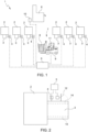
Figure 1 is a schematic view, with parts removed for the sake of clarity, of a system for manufacturing metal objects by die-casting in accordance with the present invention; -
Figure 2 is a schematic view, with parts removed for the sake of clarity, of a detail of the system for manufacturing metal objects by die-casting ofFigure 1 ; and -
Figure 3 is a schematic view, with parts removed for the sake of clarity, of the system for manufacturing metal objects by die-casting ofFigure 1 , in accordance with a second embodiment of the present invention. - With reference to
Figure 1 , a system for manufacturing metal objects by die-casting is indicated as a whole withreference numeral 1. - In particular, the present invention relates to a
system 1 for manufacturing metal objects by die-casting a liquid metal material in a foundry unit, without thereby limiting the wide range of potential applications of the present invention. - In accordance with the present invention, the
system 1 comprises a plurality ofmachines 2 for the die-casting of liquid metal material; a plurality of maintainingfurnaces 3, each of which is configured to contain the liquid metal material and comprises ameasuring device 4 configured to provide a level signal indicating the level of the liquid metal material inside the respective maintainingfurnace 3; acontrol unit 5 configured to receive the level signals provided by themeasuring devices 4, process such level signals, and emit guidance signals for the supply operations of the maintainingfurnaces 3. - In the particular example shown in
Figure 1 , sixmachines 2 for the die-casting are shown in a row as well as six maintainingfurnaces 3, each of which is associated with arespective machine 2 for the die-casting. The number and the arrangement of themachines 2 for the die-casting and of the maintainingfurnaces 3 are purely illustrative and are not to be understood as limiting of the scope of protection of the present invention. - Moreover, in accordance with a variant of the present invention, not shown in the attached figures, at least one maintaining
furnace 3 is associated with a plurality ofmachines 2 for the die-casting. - In accordance with a further variant of the present invention, not shown in the attached figures, at least one
machine 2 for the die-casting is associated with a plurality of maintainingfurnaces 3. - Each maintaining
furnace 3 is configured to maintain the liquid metal material within a predefined temperature range, and feed the liquid metal material to therespective machine 2 for the die-casting. - In the preferred embodiment, non-limiting of the present invention, each
measuring device 4 comprises a laser sensor configured to measure the level of the liquid metal material inside the respective maintainingfurnace 3. - More specifically, the laser sensor is configured to emit a laser beam that is reflected by the surface of the liquid metal material contained inside the maintaining
furnace 3. This reflection of the laser beam is captured by the laser sensor, which, by triangulation, determines the distance between the laser sensor and the surface of the liquid metal material contained inside the maintainingfurnace 3. - In accordance with alternative embodiments, the
measuring device 4 comprises an ultrasonic level sensor or a radar level sensor. - The
control unit 5 is configured to emit a consent signal for the feeding of the liquid metal material to the maintainingfurnaces 3 and to determine a priority among the maintainingfurnaces 3 to be supplied with the liquid metal material according to the level signals provided by the measuringdevices 4. - Moreover, the
system 1 comprises a melting furnace 6 configured to supply liquid metal material; a conveyingassembly 7 of the liquid metal material, configured to feed the liquid metal material from the melting furnace 6 to each maintainingfurnace 3 to be supplied. - The melting furnace 6 is configured to receive a solid metal material, melt the solid metal material, and supply the liquid metal material.
- Although a single melting furnace 6 is shown in the particular example of
Figure 1 , in accordance with alternative embodiments, thesystem 1 can comprise a plurality of melting furnaces 6. - In the particular example shown in
Figure 1 , the conveyingassembly 7 comprises a ladle 8 having a capacity, and a cart 9, configured to be guided by an operator so as to transport the ladle 8 to the maintainingfurnaces 3. - Moreover, the
system 1 comprises two signalingdevices 10 and 11, connected to thecontrol unit 5 and configured to receive the guidance signals for the supply operations of the maintainingfurnaces 3 emitted by thecontrol unit 5, so as to be perceived and understood by the operator. - In particular, the
signaling device 10 is stationary and comprises a screen configured to display said guidance signals. - The signaling device 11 is mobile and is configured to be transported by the cart 9 and to be viewed by the operator on board the cart 9.
- More specifically, the signaling device 11 is a tablet or a laptop screen.
- With reference to
Figure 2 , each maintainingfurnace 3 comprises alid 12 with automatic opening connected to thecontrol unit 5. - The
control unit 5 is configured to control the opening and the closing of eachlid 12. - Moreover, the
control unit 5 comprises a memory containing aminimum level 13 and amaximum level 14 of the liquid metal material for each maintainingfurnace 3, and an average rate of consumption of the metal material, not shown in the attached figures, for eachmachine 2 for the die-casting. - With reference to
Figure 3 , a second embodiment of thesystem 15 for manufacturing metal objects by die-casting a liquid metal material is shown. - The
system 15 comprises a conveyingassembly 16, configured to feed the liquid metal material to the maintainingfurnaces 3 automatically, without the intervention of an operator. - The conveying
assembly 16 comprises the ladle 8 and acart 17 that is self-driven configured to transport the ladle 8 to the maintainingfurnaces 3. - The
cart 17 that is self-driven comprises acommunication device 18 configured to exchange signals with thecontrol unit 5. - In particular, the
communication device 18 is configured to receive from thecontrol unit 5 the guidance signals for the supply operations of the maintainingfurnaces 3 and to send to thecontrol unit 5 signals indicating the position of thecart 17 that is self-driven. - Moreover, the
system 15 comprises a meltingfurnace 19, which comprises acommunication device 20 configured to receive from thecontrol unit 5 the guidance signals for the supply operations of the maintainingfurnaces 3 and to send to thecontrol unit 5 signals indicating the state of the meltingfurnace 19 and of the metal material in themelting furnace 19. - In use and with reference to
Figure 1 , before the start of the supply operations, the memory is uploaded with data indicating the maximum and minimum levels of each maintainingfurnace 3 and the average rates of consumption of eachmachine 2 for the die-casting. - The liquid metal material is supplied from each maintaining
furnace 3 to the associatedmachine 2 for the die-casting. - In case the level of liquid metal material of at least one of the maintaining
furnaces 3 measured by therespective measuring device 4 falls below the minimum level 13 (Figure 2 ), thecontrol unit 5 emits a consent signal for the supply of the liquid metal material from the melting furnace 6. - Moreover, the
control unit 5 emits an indication signal of the maintainingfurnace 3 to be supplied associated with the consent signal. - Said consent and indication signals are received by the signaling
devices 10 and 11 and are displayed on the screen of thesignaling devices 10 and 11, so as to be understandable for the operator in charge of the supply operations. - The operator guides the cart 9 so as to position the ladle 8 at the melting furnace 6 and initiates the supply of the liquid metal material from the melting furnace 6 into the ladle 8.
- Once the ladle 8 is full of a given amount of liquid metal material, the operator guides the cart 9 so as to position the ladle 8 at the maintaining
furnace 3 to be filled signaled by the signalingdevices 10 and 11. - In accordance with the preferred embodiment of the present invention, the
control unit 5 commands the automatic opening of the lid 12 (Figure 2 ) of the maintainingfurnace 3 to be supplied, for allowing the feeding of the maintainingfurnace 3 to be supplied with the liquid metal material contained in the ladle 8. - In accordance with an alternative embodiment of the present invention, the opening of the
lid 12 of the maintainingfurnace 3 to be supplied is commanded manually by the operator. - In case the sum of the volumes comprised between the maximum level 14 (
Figure 2 ) and the level of the liquid metal material of each maintainingfurnace 3 measured by therespective measuring device 4 equals or exceeds the capacity of the ladle 8, thecontrol unit 5 emits the consent signal for the supply of the liquid metal material from the melting furnace 6. - Moreover, the
control unit 5 emits an indication signal associated with the consent signal, indicating the maintainingfurnaces 3 to be supplied and the priority sequence of the supply of the maintainingfurnaces 3. - In such case, the melting furnace 6 dispenses an amount of metal material into the ladle 8 such to fill completely the capacity of the ladle 8.
- In accordance with a variant of the present invention, the
control unit 5 predicts the level of liquid metal material of each maintainingfurnace 3 as a function of the average rate of consumption of the associatedmachine 2 for the die-casting and the level of liquid metal material measured by therespective measuring device 4. - In accordance with such variant, the
control unit 5 emits the supply consent signal before the sum of the volumes comprised between the maximum level 14 (Figure 2 ) and the level of liquid metal material of each maintainingfurnace 3 measured by therespective measuring device 4 equals or exceeds the capacity of the ladle 8. - In use and with reference to
Figure 3 , thesystem 15 carries out the operations for supplying the maintainingfurnaces 3 automatically. - The
control unit 5 communicates with thecart 17 that is self-driven via thecommunication device 18 and initially commands the positioning of thecart 17 that is self-driven at the meltingfurnace 19. - When the melting
furnace 19 receives, via thecommunication device 20, the supply consent signal emitted by thecontrol unit 5, the meltingfurnace 19 automatically initiates the supply of a certain amount of liquid metal material into the ladle 8. - When said supply is terminated, the
communication device 20 emits an end-supply signal. - The
control unit 5 receives the end-supply signal and commands, by sending a movement signal to thecommunication device 18, the automatic movement of thecart 17 that is self-driven toward the maintainingfurnaces 3 to be supplied. - Moreover, the
cart 17 that is self-driven provides for the pouring of the liquid metal material from the ladle 8 into each maintainingfurnace 3 to be supplied in an automated manner. - In accordance with a variant of the second embodiment, the supply of a given amount of liquid metal material from the melting
furnace 19 into the ladle 8 and the pouring of the liquid metal material from the ladle 8 to each maintainingfurnace 3 to be supplied occur under the supervision of at least one operator. - Finally, it is evident that variants can be made to the present invention with respect to the described embodiments without thereby departing from the scope of protection of the appended claims.
Claims (10)
- A system for manufacturing metal objects by die-casting a liquid metal material; the system (1; 15) comprising:- a melting furnace (6; 19) configured to supply liquid metal material;- a plurality of machines (2) for the die-casting of liquid metal material;- a plurality of maintaining furnaces (3), each of which is associated with at least one respective machine (2) for the die-casting, is configured to contain the liquid metal material, maintain the liquid metal material within a predefined temperature range, and feed the liquid metal material to the at least one respective machine (2) for the die-casting, and comprises a measuring device (4) configured to provide a level signal indicating the level of the liquid metal material inside the respective maintaining furnace (3) ;- a conveying assembly (7; 16) of the liquid metal material, configured to feed the liquid metal material from the melting furnace (6; 19) to each maintaining furnace (3); and- a control unit (5) configured to determine a priority among the maintaining furnaces (3) to be supplied with the liquid metal material according to the level signals provided by the measuring devices (4);the conveying assembly (7; 16) comprising a ladle (8) having a capacity, and a cart (9; 17), configured to transport the ladle (8) to at least one of the said maintaining furnaces (3); the control unit (5) being configured to emit a consent signal for the supply of the liquid metal material from the melting furnace (6; 19) if the sum of the volumes comprised between the maximum level (14) and the level of liquid metal material of each maintaining furnace (3) measured by the respective measuring device (4) equals or exceeds the capacity of the ladle (8); the control unit (5) being configured to emit an indication signal associated with the consent signal and indicating the maintaining furnaces (3) to be supplied and the priority sequence of the supply of the maintaining furnaces (3).
- The system as claimed in Claim 1, and comprising at least one signaling device (10; 11), which can be activated in response to the consent signal; the signaling device (10; 11) comprising a graphical interface configured to display information related to the maintaining furnaces (3) to be supplied and to the consent signal for the supply of the liquid metal material.
- The system as claimed in Claim 1 or 2, wherein the control unit (5) comprises a memory containing a minimum level (13) and a maximum level (14) of the liquid metal material for each maintaining furnace (3); and wherein the control unit (5) is configured to emit the consent signal for the supply of liquid metal material when the level of the liquid metal material of at least one of the maintaining furnaces (3) measured by the respective measuring device (4) falls below the minimum level (13).
- The system as claimed in Claim 3, wherein the memory contains an average rate of consumption of the liquid metal material of each machine (2) for the die-casting; the control unit (5) being configured to predict the level of liquid metal material of each maintaining furnace (3) as a function of the average rate of consumption of the at least one machine (2) for the die-casting associated and the level of liquid metal material measured by the respective measuring device (4).
- The system as claimed in any one of the foregoing Claims, wherein the cart (17) is self-driven.
- The system as claimed in any one of the foregoing Claims, wherein each maintaining furnace (3) comprises a lid (12) with automatic opening; the control unit (5) being configured to control the opening and the closing of each lid (12).
- The system as claimed in any one of the foregoing Claims, wherein the measuring device (4) comprises a laser sensor.
- A method for manufacturing metal objects by die-casting a liquid metal material; the method comprises:- providing liquid metal material by means of a melting furnace (6; 19);- providing a plurality of machines (2) for the die-casting of liquid metal material;- providing a plurality of maintaining furnaces (3), each of which is associated with at least one respective machine (2) for the die-casting and is configured to contain the liquid metal material, maintain the liquid metal material within a predefined temperature range, and feed the liquid metal material to the at least one respective machine (2) for the die-casting;- measuring the level of the liquid metal material inside each maintaining furnace (3);- determining a priority among the maintaining furnaces (3) to be supplied with the liquid metal material as a function of the measured levels;- feeding the liquid metal material from the melting furnace (6; 19) to each maintaining furnace (3) to be supplied via a ladle (8), which has a given capacity and is transported by a cart (9; 17);- emitting a consent signal for the supply of liquid metal material from the melting furnace (6; 19) if the sum of the volumes of each maintaining furnace (3) comprised between the maximum level (14) and the level of liquid metal material measured equals or exceeds the capacity of the ladle (8); and- emitting an indication signal associated with the consent signal and indicating the maintaining furnaces (3) to be supplied and the priority sequence of the supply of the maintaining furnaces (3).
- The method as claimed in Claim 8, comprising containing in a memory a minimum level (13) and a maximum level (14) of the liquid metal material for each maintaining furnace (3); and emitting the consent signal for the supply of the liquid metal material if the measured level of liquid metal material of at least one of the maintaining furnaces (3) falls below the minimum level (13).
- The system as claimed in Claim 8 or 9, comprising predictively determining the level of liquid metal material within each maintaining furnace (3) as a function of the average consumption rate of the at least one associated machine (2) for the die-casting and the respective level of liquid metal material measured.
Priority Applications (1)
| Application Number | Priority Date | Filing Date | Title |
|---|---|---|---|
| HRP20231345TT HRP20231345T1 (en) | 2019-09-30 | 2020-09-30 | System and method for manufacturing metal objects by die-casting |
Applications Claiming Priority (2)
| Application Number | Priority Date | Filing Date | Title |
|---|---|---|---|
| IT102019000017540A IT201900017540A1 (en) | 2019-09-30 | 2019-09-30 | SYSTEM AND METHOD FOR MAKING METALLIC OBJECTS BY DIE CASTING |
| PCT/IB2020/059157 WO2021064599A1 (en) | 2019-09-30 | 2020-09-30 | System and method for manufacturing metal objects by die-casting |
Publications (3)
| Publication Number | Publication Date |
|---|---|
| EP4037851A1 EP4037851A1 (en) | 2022-08-10 |
| EP4037851C0 EP4037851C0 (en) | 2023-09-27 |
| EP4037851B1 true EP4037851B1 (en) | 2023-09-27 |
Family
ID=69469070
Family Applications (1)
| Application Number | Title | Priority Date | Filing Date |
|---|---|---|---|
| EP20797174.8A Active EP4037851B1 (en) | 2019-09-30 | 2020-09-30 | System and method for manufacturing metal objects by die-casting |
Country Status (8)
| Country | Link |
|---|---|
| EP (1) | EP4037851B1 (en) |
| ES (1) | ES2962780T3 (en) |
| HR (1) | HRP20231345T1 (en) |
| HU (1) | HUE063589T2 (en) |
| IT (1) | IT201900017540A1 (en) |
| MX (1) | MX2022003805A (en) |
| PL (1) | PL4037851T3 (en) |
| WO (1) | WO2021064599A1 (en) |
Family Cites Families (5)
| Publication number | Priority date | Publication date | Assignee | Title |
|---|---|---|---|---|
| DD294442A5 (en) * | 1989-05-02 | 1991-10-02 | Unirobot Kft.,Hu | METHOD, DEVICE AND ROBOT VEHICLE FOR THE AUTOMATIC PROCESSING OF PRESS CASTING MACHINES WITH LIQUID METAL |
| GB2421921B (en) * | 2002-11-29 | 2006-09-06 | Hoei Shokai Co Ltd | Pressure controlling apparatus, transporting vehicle and a unit for controlling pressure difference |
| WO2007077800A1 (en) * | 2005-12-28 | 2007-07-12 | Hoei Shokai Co., Ltd. | Container, molten metal supply system and method |
| CN205128891U (en) * | 2015-11-02 | 2016-04-06 | 浙江鑫鸿拉链有限公司 | Automatic delivery system of die casting machine kirsite stock |
| DE102016119702A1 (en) * | 2016-10-17 | 2018-04-19 | Hochschule für angewandte Wissenschaften Ansbach | Apparatus and method for distributing cleaning intervals in melting furnaces in a melting and die casting operation |
-
2019
- 2019-09-30 IT IT102019000017540A patent/IT201900017540A1/en unknown
-
2020
- 2020-09-30 WO PCT/IB2020/059157 patent/WO2021064599A1/en not_active Ceased
- 2020-09-30 HU HUE20797174A patent/HUE063589T2/en unknown
- 2020-09-30 MX MX2022003805A patent/MX2022003805A/en unknown
- 2020-09-30 EP EP20797174.8A patent/EP4037851B1/en active Active
- 2020-09-30 ES ES20797174T patent/ES2962780T3/en active Active
- 2020-09-30 PL PL20797174.8T patent/PL4037851T3/en unknown
- 2020-09-30 HR HRP20231345TT patent/HRP20231345T1/en unknown
Also Published As
| Publication number | Publication date |
|---|---|
| PL4037851T3 (en) | 2024-01-22 |
| EP4037851C0 (en) | 2023-09-27 |
| HUE063589T2 (en) | 2024-01-28 |
| WO2021064599A1 (en) | 2021-04-08 |
| EP4037851A1 (en) | 2022-08-10 |
| HRP20231345T1 (en) | 2024-02-16 |
| MX2022003805A (en) | 2022-06-16 |
| ES2962780T3 (en) | 2024-03-21 |
| IT201900017540A1 (en) | 2021-03-30 |
Similar Documents
| Publication | Publication Date | Title |
|---|---|---|
| CA1080423A (en) | Conveyor means for feeding a flux powder into the mould of a continuous steel casting plant | |
| KR930000090B1 (en) | Continuous casting method and apparatus for implementing the method | |
| KR20130138209A (en) | Method and control and tracking system of the charge of material transported by a continuous supply conveyor of a metallurgical furnace, particularly an electric furnace for the production of steel | |
| EP4045861B1 (en) | Sensor controlled launder flow | |
| WO2011030618A1 (en) | Molten metal pouring machine control system, molten metal pouring equipment, and molten metal pouring method | |
| US10010962B1 (en) | Module and system for controlling and recording welding data, and welding wire feeder | |
| CN115818157B (en) | Intelligent feed bin management system and method for blast furnace | |
| KR101340066B1 (en) | Melt transport and tilting system | |
| WO2021064599A1 (en) | System and method for manufacturing metal objects by die-casting | |
| KR20180014367A (en) | Apparatus for predicting abnormality of continuous casting | |
| CN102019418A (en) | Method for supplying molten metal from melting furnace into processing ladle and device using same | |
| US20250189230A1 (en) | Device for Monitoring an Apparatus for Induction Heating of a Metal Material, Method for Automatic Loading and Control System | |
| US20050133192A1 (en) | Tundish control | |
| KR101238994B1 (en) | Molten metal continuous supply system in metal casting | |
| EP3551361B1 (en) | System for pouring molten metal from a crucible | |
| US20240139801A1 (en) | Flux feeding apparatus and flux optimization selection method | |
| KR20120077421A (en) | System and method for controlling turning position of ladle turret | |
| CN206047060U (en) | A kind of feeding system of casting battery grid | |
| JP4190786B2 (en) | Molten metal supply system, molten metal supply device and vehicle | |
| US20230241670A1 (en) | Liquid metal ejector level sensing system and methods thereof | |
| US20200363131A1 (en) | Sealed tilt pour electric induction furnaces for reactive alloys and metals | |
| WO2011145145A1 (en) | Flux loading device, continuous casting device, flux loading method, and continuous casting method | |
| CN107004103A (en) | Metallurgical tank with multiple transponders | |
| US10302417B2 (en) | Use of a laser measuring system and a pulse gas flow to enable a feedback controlled mold powder application | |
| CN108103252A (en) | A kind of reclaiming system of desulfurization slag iron |
Legal Events
| Date | Code | Title | Description |
|---|---|---|---|
| REG | Reference to a national code |
Ref country code: HR Ref legal event code: TUEP Ref document number: P20231345T Country of ref document: HR |
|
| STAA | Information on the status of an ep patent application or granted ep patent |
Free format text: STATUS: UNKNOWN |
|
| STAA | Information on the status of an ep patent application or granted ep patent |
Free format text: STATUS: THE INTERNATIONAL PUBLICATION HAS BEEN MADE |
|
| PUAI | Public reference made under article 153(3) epc to a published international application that has entered the european phase |
Free format text: ORIGINAL CODE: 0009012 |
|
| STAA | Information on the status of an ep patent application or granted ep patent |
Free format text: STATUS: REQUEST FOR EXAMINATION WAS MADE |
|
| 17P | Request for examination filed |
Effective date: 20220326 |
|
| AK | Designated contracting states |
Kind code of ref document: A1 Designated state(s): AL AT BE BG CH CY CZ DE DK EE ES FI FR GB GR HR HU IE IS IT LI LT LU LV MC MK MT NL NO PL PT RO RS SE SI SK SM TR |
|
| DAV | Request for validation of the european patent (deleted) | ||
| DAX | Request for extension of the european patent (deleted) | ||
| GRAP | Despatch of communication of intention to grant a patent |
Free format text: ORIGINAL CODE: EPIDOSNIGR1 |
|
| STAA | Information on the status of an ep patent application or granted ep patent |
Free format text: STATUS: GRANT OF PATENT IS INTENDED |
|
| INTG | Intention to grant announced |
Effective date: 20230414 |
|
| GRAS | Grant fee paid |
Free format text: ORIGINAL CODE: EPIDOSNIGR3 |
|
| GRAA | (expected) grant |
Free format text: ORIGINAL CODE: 0009210 |
|
| STAA | Information on the status of an ep patent application or granted ep patent |
Free format text: STATUS: THE PATENT HAS BEEN GRANTED |
|
| AK | Designated contracting states |
Kind code of ref document: B1 Designated state(s): AL AT BE BG CH CY CZ DE DK EE ES FI FR GB GR HR HU IE IS IT LI LT LU LV MC MK MT NL NO PL PT RO RS SE SI SK SM TR |
|
| REG | Reference to a national code |
Ref country code: GB Ref legal event code: FG4D |
|
| REG | Reference to a national code |
Ref country code: CH Ref legal event code: EP |
|
| REG | Reference to a national code |
Ref country code: DE Ref legal event code: R096 Ref document number: 602020018386 Country of ref document: DE |
|
| REG | Reference to a national code |
Ref country code: IE Ref legal event code: FG4D |
|
| U01 | Request for unitary effect filed |
Effective date: 20231019 |
|
| U07 | Unitary effect registered |
Designated state(s): AT BE BG DE DK EE FI FR IT LT LU LV MT NL PT SE SI Effective date: 20231027 |
|
| U20 | Renewal fee for the european patent with unitary effect paid |
Year of fee payment: 4 Effective date: 20231030 |
|
| REG | Reference to a national code |
Ref country code: NO Ref legal event code: T2 Effective date: 20230927 |
|
| PG25 | Lapsed in a contracting state [announced via postgrant information from national office to epo] |
Ref country code: GR Free format text: LAPSE BECAUSE OF FAILURE TO SUBMIT A TRANSLATION OF THE DESCRIPTION OR TO PAY THE FEE WITHIN THE PRESCRIBED TIME-LIMIT Effective date: 20231228 |
|
| PGFP | Annual fee paid to national office [announced via postgrant information from national office to epo] |
Ref country code: ES Payment date: 20231031 Year of fee payment: 4 |
|
| REG | Reference to a national code |
Ref country code: SK Ref legal event code: T3 Ref document number: E 42650 Country of ref document: SK |
|
| REG | Reference to a national code |
Ref country code: HU Ref legal event code: AG4A Ref document number: E063589 Country of ref document: HU |
|
| PG25 | Lapsed in a contracting state [announced via postgrant information from national office to epo] |
Ref country code: RS Free format text: LAPSE BECAUSE OF FAILURE TO SUBMIT A TRANSLATION OF THE DESCRIPTION OR TO PAY THE FEE WITHIN THE PRESCRIBED TIME-LIMIT Effective date: 20230927 Ref country code: GR Free format text: LAPSE BECAUSE OF FAILURE TO SUBMIT A TRANSLATION OF THE DESCRIPTION OR TO PAY THE FEE WITHIN THE PRESCRIBED TIME-LIMIT Effective date: 20231228 |
|
| PGFP | Annual fee paid to national office [announced via postgrant information from national office to epo] |
Ref country code: TR Payment date: 20231107 Year of fee payment: 4 Ref country code: RO Payment date: 20231106 Year of fee payment: 4 Ref country code: NO Payment date: 20231120 Year of fee payment: 4 Ref country code: HU Payment date: 20231102 Year of fee payment: 4 Ref country code: CZ Payment date: 20231108 Year of fee payment: 4 Ref country code: CH Payment date: 20231101 Year of fee payment: 4 |
|
| REG | Reference to a national code |
Ref country code: HR Ref legal event code: ODRP Ref document number: P20231345T Country of ref document: HR Payment date: 20231108 Year of fee payment: 4 |
|
| REG | Reference to a national code |
Ref country code: HR Ref legal event code: T1PR Ref document number: P20231345 Country of ref document: HR |
|
| REG | Reference to a national code |
Ref country code: ES Ref legal event code: FG2A Ref document number: 2962780 Country of ref document: ES Kind code of ref document: T3 Effective date: 20240321 |
|
| PG25 | Lapsed in a contracting state [announced via postgrant information from national office to epo] |
Ref country code: IS Free format text: LAPSE BECAUSE OF FAILURE TO SUBMIT A TRANSLATION OF THE DESCRIPTION OR TO PAY THE FEE WITHIN THE PRESCRIBED TIME-LIMIT Effective date: 20240127 |
|
| PG25 | Lapsed in a contracting state [announced via postgrant information from national office to epo] |
Ref country code: SM Free format text: LAPSE BECAUSE OF FAILURE TO SUBMIT A TRANSLATION OF THE DESCRIPTION OR TO PAY THE FEE WITHIN THE PRESCRIBED TIME-LIMIT Effective date: 20230927 Ref country code: IS Free format text: LAPSE BECAUSE OF FAILURE TO SUBMIT A TRANSLATION OF THE DESCRIPTION OR TO PAY THE FEE WITHIN THE PRESCRIBED TIME-LIMIT Effective date: 20240127 |
|
| PGFP | Annual fee paid to national office [announced via postgrant information from national office to epo] |
Ref country code: SK Payment date: 20231106 Year of fee payment: 4 |
|
| PGFP | Annual fee paid to national office [announced via postgrant information from national office to epo] |
Ref country code: PL Payment date: 20231102 Year of fee payment: 4 Ref country code: HR Payment date: 20240126 Year of fee payment: 4 |
|
| REG | Reference to a national code |
Ref country code: DE Ref legal event code: R097 Ref document number: 602020018386 Country of ref document: DE |
|
| PG25 | Lapsed in a contracting state [announced via postgrant information from national office to epo] |
Ref country code: MC Free format text: LAPSE BECAUSE OF FAILURE TO SUBMIT A TRANSLATION OF THE DESCRIPTION OR TO PAY THE FEE WITHIN THE PRESCRIBED TIME-LIMIT Effective date: 20230927 |
|
| REG | Reference to a national code |
Ref country code: IE Ref legal event code: MM4A |
|
| PG25 | Lapsed in a contracting state [announced via postgrant information from national office to epo] |
Ref country code: IE Free format text: LAPSE BECAUSE OF NON-PAYMENT OF DUE FEES Effective date: 20230930 |
|
| PG25 | Lapsed in a contracting state [announced via postgrant information from national office to epo] |
Ref country code: MC Free format text: LAPSE BECAUSE OF FAILURE TO SUBMIT A TRANSLATION OF THE DESCRIPTION OR TO PAY THE FEE WITHIN THE PRESCRIBED TIME-LIMIT Effective date: 20230927 Ref country code: IE Free format text: LAPSE BECAUSE OF NON-PAYMENT OF DUE FEES Effective date: 20230930 |
|
| PLBE | No opposition filed within time limit |
Free format text: ORIGINAL CODE: 0009261 |
|
| STAA | Information on the status of an ep patent application or granted ep patent |
Free format text: STATUS: NO OPPOSITION FILED WITHIN TIME LIMIT |
|
| 26N | No opposition filed |
Effective date: 20240628 |
|
| REG | Reference to a national code |
Ref country code: HR Ref legal event code: PBON Ref document number: P20231345 Country of ref document: HR Effective date: 20240930 |
|
| PG25 | Lapsed in a contracting state [announced via postgrant information from national office to epo] |
Ref country code: CZ Free format text: LAPSE BECAUSE OF NON-PAYMENT OF DUE FEES Effective date: 20240930 |
|
| REG | Reference to a national code |
Ref country code: CH Ref legal event code: PL |
|
| U90 | Renewal fees not paid: noting of loss of rights |
Free format text: RENEWAL FEE NOT PAID FOR YEAR 05 Effective date: 20250422 |
|
| GBPC | Gb: european patent ceased through non-payment of renewal fee |
Effective date: 20240930 |
|
| REG | Reference to a national code |
Ref country code: SK Ref legal event code: MM4A Ref document number: E 42650 Country of ref document: SK Effective date: 20240930 |
|
| PG25 | Lapsed in a contracting state [announced via postgrant information from national office to epo] |
Ref country code: GB Free format text: LAPSE BECAUSE OF NON-PAYMENT OF DUE FEES Effective date: 20240930 |
|
| PG25 | Lapsed in a contracting state [announced via postgrant information from national office to epo] |
Ref country code: NO Free format text: LAPSE BECAUSE OF NON-PAYMENT OF DUE FEES Effective date: 20240930 Ref country code: HU Free format text: LAPSE BECAUSE OF NON-PAYMENT OF DUE FEES Effective date: 20241001 |
|
| PG25 | Lapsed in a contracting state [announced via postgrant information from national office to epo] |
Ref country code: HR Free format text: LAPSE BECAUSE OF NON-PAYMENT OF DUE FEES Effective date: 20240930 |
|
| PG25 | Lapsed in a contracting state [announced via postgrant information from national office to epo] |
Ref country code: CH Free format text: LAPSE BECAUSE OF NON-PAYMENT OF DUE FEES Effective date: 20240930 |
|
| PG25 | Lapsed in a contracting state [announced via postgrant information from national office to epo] |
Ref country code: RO Free format text: LAPSE BECAUSE OF NON-PAYMENT OF DUE FEES Effective date: 20240930 |
|
| PG25 | Lapsed in a contracting state [announced via postgrant information from national office to epo] |
Ref country code: SK Free format text: LAPSE BECAUSE OF NON-PAYMENT OF DUE FEES Effective date: 20240930 Ref country code: CY Free format text: LAPSE BECAUSE OF FAILURE TO SUBMIT A TRANSLATION OF THE DESCRIPTION OR TO PAY THE FEE WITHIN THE PRESCRIBED TIME-LIMIT; INVALID AB INITIO Effective date: 20200930 |
|
| U93 | Unitary patent lapsed |
Free format text: RENEWAL FEE NOT PAID Effective date: 20240930 |
|
| REG | Reference to a national code |
Ref country code: ES Ref legal event code: FD2A Effective date: 20251027 |
|
| PG25 | Lapsed in a contracting state [announced via postgrant information from national office to epo] |
Ref country code: PL Free format text: LAPSE BECAUSE OF NON-PAYMENT OF DUE FEES Effective date: 20240930 |
|
| PG25 | Lapsed in a contracting state [announced via postgrant information from national office to epo] |
Ref country code: ES Free format text: LAPSE BECAUSE OF NON-PAYMENT OF DUE FEES Effective date: 20241001 |